High-quality single-walled carbon nanotube films as current collectors for flexible supercapacitors†
Sheng
Zhu
abc,
Zeyao
Zhang
*ac,
Jian
Sheng
a,
Guodong
Jia
a,
Jiangfeng
Ni
 *d and
Yan
Li
 *ac
*ac
aCollege of Chemistry and Molecular Engineering, Peking University, Beijing 100871, China. E-mail: yanli@pku.edu.cn; zeyaozhang@pku.edu.cn
bInstitute of Molecular Science, Shanxi University, Taiyuan 030006, China
cInstitute of Advanced Functional Materials and Devices, Shanxi University, Taiyuan 030031, China
dSchool of Physical Science and Technology, Soochow University, Suzhou 215006, P. R. China. E-mail: jeffni@suda.edu.cn
First published on 1st March 2023
Abstract
Current collectors with light weight, excellent durability, and mechanical robustness are highly demanded for flexible energy storage devices. Here, we prepare free-standing single-walled carbon nanotube films (SWCNFs) with a three-dimensional interconnected porous structure via floating catalyst chemical vapor deposition and apply them as current collectors for flexible supercapacitors. These SWCNFs present high mass loading efficiency, outstanding mechanical robustness, and excellent anti-corrosion properties, showing distinct advantages over conventional metal foil current collectors. The loading efficiency is up to 75% for pseudocapacitive cobalt(II) carbonate hydroxide materials, exhibiting superior electrochemical performance in terms of specific capacitance, rate capability, and cycling performance. In addition, the assembled hybrid supercapacitors (SWCNF-cobalt carbonate hydroxide//SWCNF-polyaniline) exhibit outstanding flexibility under various bending deformations and long-term stability. Free-standing SWCNFs have proven to be promising candidates for ultralight current collectors for flexible supercapacitors.
10th anniversary statementI had been working as an associate editor of Journal of Materials Chemistry A from 2013 to 2016 and experienced the rapid growth of the journal. Now Journal of Materials Chemistry A has become one of the most influential journals in the field of materials science, especially materials for energy and sustainability. Now we are celebrating its 10th anniversary. Witnessing the great achievement in the past, we can expect that Journal of Materials Chemistry A will have an even more glorious future. Let's work together for its further development! |
Introduction
Rapid development in wearable and portable electronics for smartphones, bendable displays, biomedical devices and military applications has accelerated the exploration for flexible and light-weight energy storage devices.1–5 Flexible solid supercapacitors (FSSCs), which store electrical charge at the electrode/electrolyte interface, have drawn considerable attention because of their large output power density, fast charge–discharge rates, excellent safety, and unrivaled durability.6–8 For the past decade, the research interest has been mainly focused on the electrode materials including carbon nanomaterials, transition metal oxides/sulfides/carbides, and conductive polymers.9–13 In stark contrast, there are rather limited reports on the current collectors for FSSCs.14–16Current collectors, as essential components to support the electrode materials and implement fast electron transportation between leads and materials,17 demonstrate a substantial impact on the overall performance of supercapacitors. The widely used current collectors are metals such as nickel foam,18,19 copper foam,20,21 stainless steel mesh22,23 and carbon materials including carbon cloth and carbon paper.24–26 Three primary issues for metal collectors need to be noted (1) the high density (e.g., nickel foam ∼30 mg cm−2): results in low loading efficiency (denoted as  where me is the mass of electrode materials and mt is the total mass of current collectors and effective electrode materials), severely hindering the gravimetric/volumetric capacitance and energy density of the entire device; (2) the limited contact area and weak adhesion with the electrode materials make the electrode materials desquamate from current collectors, leading to poor cycling stability, especially at high scan rates;27 (3) unsatisfying durability during repeated charge/discharge processes brings about obvious electrochemical corrosion of the current collectors after 500 cycles.28 Compared with metals, conventional carbon candidates, such as carbon cloths and carbon papers, have better chemical stability but still suffer from the low loading efficiency as well as the fragility of carbon papers. In recent years, nanocarbon material (including graphene and carbon nanotubes) based current collectors have gained considerable attention. Theoretically, nanocarbon materials have the great advantage of much higher surface area and stability which might be able to address the above issues. However, the macroscale aggregates used as current collectors were often prepared by a solution process, which introduced defects and oxygen-containing groups that would decrease electrical conductivity and cycling life.29–32 Meanwhile, it is also challenging to retain the high surface area of the aggregates in such processes. Therefore, it is highly desired to exploit different forms of macroscopic assemblies of nanocarbon materials prepared with updated methods as current collectors for high-performance FSSCs.
In this study, we prepared high-quality single-walled carbon nanotube (SWCNT) films (SWCNFs) as ultralight, thin, mechanically tough, and robust current collectors for FSSCs. The conventional Ni foam and carbon cloth are also tested for comparison. As two types of pseudocapacitive materials for supercapacitors, cobalt(II) carbonate hydroxide (Co2(OH)2CO3) and polyaniline (PANI) were used as positive and negative electrode materials for assembling hybrid supercapacitors. The Co2(OH)2CO3 nanowires were loaded on these current collectors using a solvothermal method. The 3D interconnected SWCNF showed a high loading efficiency of 75% and a high specific capacitance of 408.4 F g−1 at 1 A g−1 by considering the total mass of the electrode and current collectors. The assembled hybrid FSSCs of SWCNF–Co2(OH)2CO3//SWCNF–PANI also exhibited excellent flexibility and capacitive stability.
Experimental section
Preparation of SWCNFs
SWCNFs were synthesized by the floating catalyst chemical vapor deposition (FCCVD) method. Ferrocene (0.4 wt%) and thiophene (molar ratio of S/Fe = 0.3) were dissolved in ethanol solvent to form a liquid feedstock, which was injected into a quartz tube with a microfluidic pump at a constant feeding rate of 10 μL min−1. The carrying gas is a mixture of Ar and H2 at the same rate of 300 sccm. The source solution was evaporated in a heating line kept at 140 °C. A circular piece of filter paper was placed at the end of the quartz tube and used as the collecting substrate for SWCNFs. The reaction temperature was maintained at 1100 °C for 20 min. The as-prepared SWCNFs were immersed in 25 mL distilled water with 25 mL alcohol to get transferred from the filter paper substrate. In order to remove the residue of catalysis particles, the prepared SWCNFs were treated by using acid (1.0 M HCl). After washing with distilled water and alcohol, the SWCNFs were dried for the following experiments.Fabrication of SWCNF–CO2(OH)2CO3
The Co2(OH)2CO3 single crystal nanowires were grown on a 3D porous SWCNF by a novel solvothermal synthesis strategy. In a typical process, Co(NO3)2·6H2O (1.0 mmol) and CO(NH2)2 (2.0 mmol) were dissolved in 24 mL distilled water with 6 mL alcohol under stirring. Subsequently, the homogeneous solution was transferred to a Teflon-lined stainless-steel autoclave. The preprocessed SWCNF was placed in the above solution and the reaction temperature was set as 100 °C for 6 h. After reaction, SWCNF–Co2(OH)2CO3 was washed with distilled water and alcohol, and then freeze-dried under vacuum for 24 h. For comparison, the Ni foam-Co2(OH)2CO3 and carbon cloth-Co2(OH)2CO3 were synthesized through the growth of Co2(OH)2CO3 single crystal nanowires on Ni foam and carbon cloth under the same conditions. The mass loading of Co2(OH)2CO3 on the SWCNF, Ni foam and carbon cloth is 0.12, 1.0 and 0.6 mg cm−2, respectively.Preparation of the SWCNF–PANI hybrid
The core–shell structured SWCNF–PANI hybrid was obtained using a mild chemical oxidation polymerization of aniline in acid environment. Firstly, 2.0 mL 1 M HCl was injected in 20 mL distilled water and 5 mL alcohol. Then 2.0 mmol aniline monomers were added into the solution, followed by placing the preprocessed SWCNF. After stirring for 30 minutes, the oxidant ammonium peroxodisulphate (APS) was slowly added to the mixtures (the mole ratio of APS and aniline was 1![[thin space (1/6-em)]](https://www.rsc.org/images/entities/char_2009.gif) :
:![[thin space (1/6-em)]](https://www.rsc.org/images/entities/char_2009.gif) 1). After further stirring at room temperature for 10 hours, the SWCNF–PANI was collected, washed, and freeze-dried under vacuum for 24 h. The mass loading of PANI is ∼0.07 mg cm−2.
1). After further stirring at room temperature for 10 hours, the SWCNF–PANI was collected, washed, and freeze-dried under vacuum for 24 h. The mass loading of PANI is ∼0.07 mg cm−2.
Fabrication of hybrid FSSCs
The PVA–KOH gel electrolyte was prepared as follows: generally, 12 g PVA was dissolved in 120 mL distilled water under stirring at 85 °C for 2 h. Then, 6 g KOH was dissolved in 40 mL distilled water which was then transferred into the above solutions with vigorous stirring until the solution became clear. Before fabrication, SWCNF–Co2(OH)2CO3 and SWCNF–PANI with the same size of 1.0 × 1.5 cm2 were immersed in the PVA–KOH gel electrolyte for several minutes. After drying at room temperature for evaporation of excess water, the hybrid SWCNF–Co2(OH)2CO3//SWCNF–PANI FSSCs were assembled by using the above two electrodes with a sandwich-like structure.The charges of the positive electrode (q+) and negative electrode (q−) are balanced by using the formula of q+ = q−. The mass loading for the negative electrode was determined by using the following eqn (1) and (2):33,34
| q = mΔVCm | (1) |
 | (2) |
Characterization
The sheet resistance of SWCNFs on a quartz slide was measured with a HP/Hewlett Packard 3485A multimeter connected to a four point probe (Jandel Engineering Ltd., UK, tip radius 250 μm, tip spacing 1 mm). The morphology and nanostructure of the films were characterized by field-emission scanning electron microscopy (SEM) obtained using a Hitachi S4800 and transmission electron microscopy (TEM) conducted on an FEI Tecnai F20 at an accelerating voltage of 200 kV. X-Ray diffraction (XRD) was conducted on a Panalytical XRD instrument with Cu Kα radiation (λ = 1.5406 Å). The absorption spectra of SWCNFs were collected on an ultraviolet-visible-near-infrared absorption spectrometer (UV-vis-NIR, PerkinElmer LAMBDA 750). Th Raman scattering spectrum was obtained using a Jobin Yvon LabRam HR 800 micro-Raman spectrometer equipped with excitation wavelengths of 532, 653, and 733 nm.Electrochemical measurement
Electrochemical experiments were conducted on a CHI 760E electrochemical workstation (CH Instruments Inc., Shanghai). For a three-electrode system, SWCNF–Co2(OH)2CO3 directly acted as the working electrode with the electrolyte of 1 M KOH aqueous solution. The counter electrode and reference electrode are a platinum plate and Hg/HgO electrode, respectively. The electrochemical properties were investigated by galvanostatic charge–discharge (GCD) and cyclic voltammetry (CV) measurements. Specific gravimetric and volumetric capacitances were calculated from eqn (3) and (4), respectively.35 | (3) |
 | (4) |
The gravimetric energy density (E) and power density (P) of the electrode are obtained by using eqn (5) and (6), respectively.36
 | (5) |
 | (6) |
For a two-electrode system, CV and GCD were carried out in the potential range of 0–1.4 V. Electrochemical impedance spectroscopy (EIS) was carried out at open-circuit potential and an alternating current amplitude of 10 mV in the frequency range of 105–0.01 Hz.
The effective series resistance (RESR) was estimated via dividing the voltage drop at the beginning of the discharge process by the constant discharge current with eqn (7).37
 | (7) |
Results and discussion
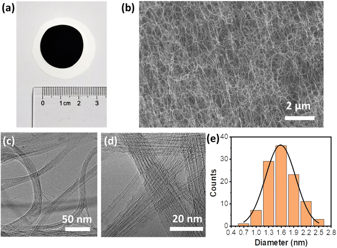
The SWCNFs were prepared based on a FCCVD system (Fig. S1a†), and collected with a piece of common filter paper. The free-standing SWCNFs were transferred from a filter paper substrate with the help of alcohol for subsequent characterization and loading of electrode materials. Fig. 1a shows a typical optical image of a SWCNF with a diameter of ca. 2.2 cm and thickness of ca. 20 μm (Fig. S1b†). The as-prepared SWCNFs are ultralight with a mass of ∼0.10 mg, and conductive with a low electrical resistance of 3 Ω sq−1. As promising candidate materials for current collectors for FSSCs, the parameters of the SWCNFs are illustrated in Table 1. From Fig. 1b and S1c,† it can be seen that SWCNTs are up to several hundred microns in length and form 3D interconnected porous structures, which is of great advantage in improving loading efficiency and facilitating mass transport.| Diameter (cm) | Thickness (μm) | Mass (mg) | Density (mg cm−3) | Sheet resistance (Ω sq−1) |
|---|---|---|---|---|
| 2.2 | 20 | 0.10 | 13.2 | 3.0 |
As depicted in Fig. 1c and d, the ultralong SWCNTs greatly promote the bundle formation induced by the strong van der Waals interaction between adjacent SWCNTs during the growth process, resulting in excellent mechanical robustness of SWCNFs to serve as current collectors. The diameter distribution of the SWCNTs was measured from the TEM images and is displayed in Fig. 1e. The SWCNTs have diameters in the range of 1.3–1.9 nm, with an average diameter of ca. 1.6 nm.
The diameters of SWCNTs are often determined by the specific features of the first and second order interband transitions of semiconducting carbon nanotubes and the first interband transition of metallic carbon nanotubes. Three obvious peaks in the optical absorption spectra of S11 (∼2170 nm), S22 (∼1190 nm) and M11 (∼830 nm) are observed for SWCNFs (Fig. 2a). Based on the Kataura plots,38 the diameters of the SWCNTs are in the range of 1.6–2.0 nm, which is well matched with the statistical result from TEM images. The Raman spectra of SWCNFs with different areas were collected with the excitation wavelengths of 532 nm, 633 nm and 785 nm, respectively. The quality of the SWCNTs was estimated based on the intensity ratio of the G-band (∼1580 cm−1) and the D-band (∼1320 cm−1).39 All the Raman spectra of the free-standing SWCNFs in Fig. 2b show a very high G-band and nearly invisible D-band. The high IG/ID values of 157.4 for 532 nm excitation and 140.6 for 633 nm excitation were obtained (Fig. S2†), suggesting well-crystallized sp2 C–C structures of the high quality SWCNFs, leading to high electrical conductivity of the film.
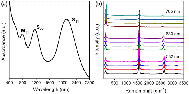 | ||
| Fig. 2 Spectroscopy characterization studies of the SWCNFs. (a) The absorption spectrum of a SWCNF. (b) The Raman spectra of SWCNFs with different excitation wavelengths. | ||
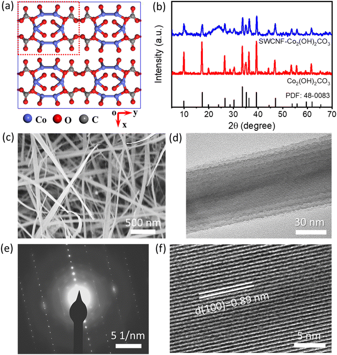
Compared to the graphene materials and MWCNTs, the as-characterized high-quality SWCNFs are more promising to serve as current collectors for FSSCs. Recent reports have shown that hydroxycarbonates are a kind of desired electrode materials in energy storage because of their environmental friendliness, natural abundance, and high theoretical pseudo-capacitance.40 As we can see from the crystal structure of Co2(OH)2CO3 in Fig. 3a, the adjacent corrugated Co2+ with double edge-sharing chains are connected by the triangular carbonate CO32− groups.41 The unique tunnel structures along the [001] direction are beneficial for the fast diffusion and free intercalation of electrolyte ions into the inner region of the electrode materials. In this study, the SWCNF supported Co2(OH)2CO3 materials were synthesized via a mild solvothermal process. As displayed in Fig. 3b, except for a broad peak centered at 26.5° from the SWCNFs, the other visible peaks in the XRD patterns are ascribed to the orthorhombic Co2(OH)2CO3 phase (JCPDS No. 48-0083, a = 0.879 nm, b = 1.015 nm, and c = 0.443 nm).42–44 The SEM images in Fig. 3c and Fig. S3a, b† reveal that the thickness of SWCNF–Co2(OH)2CO3 is about 60 μm. Co2(OH)2CO3 nanowires were in situ grown on the surface and the 3D interconnected pores of the SWCNFs ensures a high loading efficiency. From the TEM images in Fig. 3d and Fig. S3c, d (ESI†), it is observed that the average diameter of the Co2(OH)2CO3 nanowire is about 50 nm. The HRTEM image taken from a single Co2(OH)2CO3 nanowire (Fig. 3e) and the corresponding selected area electron diffraction (SAED) in Fig. 3f reveal well-resolved lattice fringes with an interplanar spacing of 0.89 nm, indexed to the (100) lattice plane. The unique atomic structures with a large interplanar distance can accelerate the transport dynamics of the electrolyte ions and provide sufficient active sites for faradaic reactions.
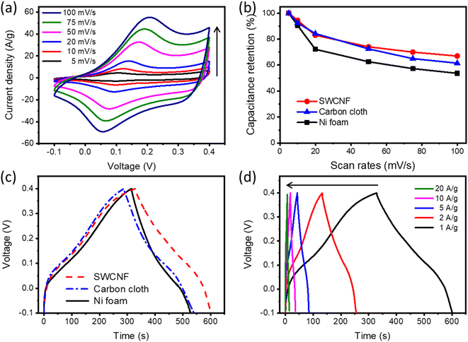
The electrochemical properties of the monolithic SWCNF–Co2(OH)2CO3 electrode were studied using a three-electrode system in 1 M KOH aqueous electrolyte. The CV curves of SWCNF–Co2(OH)2CO3 at increasing scan rates from 5 to 100 mV s−1 are demonstrated in Fig. 4a. All of the CV curves have similar shapes and show a pair of intense redox peaks with an anodic peak located at 0.1–0.2 V and cathodic peak between 0 and 0.1 V, which is attributed to the reversible electrochemical redox reaction between Co2+/Co3+ associated with OH− anions.45,46 To better understand the electrochemical performance of the free-standing SWCNFs, carbon cloth and Ni foam were used as reference current collectors. As shown in Fig. S4–S10 (ESI†), the uniform Co2(OH)2CO3 nanowires were successfully grown on the surface of the carbon cloth and Ni foam via a similar solvothermal reaction. Fig. 4b displays the rate capabilities of the Co2(OH)2CO3 material on different current collectors; as scan rates increase from 5 to 100 mV s−1, the SWCNF–Co2(OH)2CO3 electrode exhibits an overall capacitance retention of 67.1% in comparison to 61.5% for carbon cloth-Co2(OH)2CO3 and 53.7% for Ni foam-Co2(OH)2CO3 electrodes. From Fig. 4c, the calculated gravimetric capacitances of Co2(OH)2CO3 on Ni foam, carbon cloth, and the SWCNF are 425.6, 506.4, and 544.8 F g−1 without considering the weight of the current collectors. The specific capacitance of Co2(OH)2CO3 on the SWCNF is higher than the reported values of hydroxycarbonates.40,47 The GCD curves of SWCNF–Co2(OH)2CO3 at various current densities ranging from 1.0 to 20.0 A g−1 are shown in Fig. 4d. Their symmetrical triangular shapes reveal good reversibility of the Co2(OH)2CO3 electrode materials, which is consistent with the CV result.
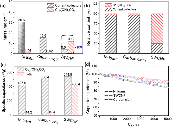
To improve the loading efficiency of the active electrode materials, decreasing the weight of the current collectors is an effective strategy. For the current collectors themselves, Ni foam and carbon cloth have much higher areal densities (30.6 and 15.6 mg cm−2, respectively) than the as-prepared SWCNFs (0.04 mg cm−2, Fig. 5a). After loading Co2(OH)2CO3, the lightweight SWCNFs with 3D developed pores shows a loading efficiency as high as 75.0%, which is far beyond that of the carbon cloth-Co2(OH)2CO3 (3.35%) and Ni foam-Co2(OH)2CO3 (3.82%) electrodes (Fig. 5b). In real applications, it is the mass and volume of the entire electrode that practically determine the gravimetric and volumetric capacitance, the two most vital parameters for estimating the storage capacity of the devices. In this regard, the Ni foam-Co2(OH)2CO3 and carbon cloth-Co2(OH)2CO3 electrodes only display very low gravimetric capacitances of 14.2 and 19.4 F g−1 (Fig. 5c and S11, ESI†), compared with the high capacity of 408.4 F g−1 for the SWCNF–Co2(OH)2CO3 electrode. Since the pure current collectors contribute little to the total capacitance, they are ignored (Fig. S12, ESI†). When it comes to the volume of the electrodes, the ultrathin SWCNF–Co2(OH)2CO3 electrode (60 μm) demonstrates a higher volumetric capacitance of 10.9 F cm−3 than Ni foam-Co2(OH)2CO3 and carbon cloth-Co2(OH)2CO3 electrodes (Fig. S13, ESI†). These results provide great potential for SWCNFs to replace the conventional heavy current collectors and serve as ultralight and thin current collectors in practical use.
Cycling stability is another vital element in the performance of a supercapacitor electrode for practical applications. Herein, the long-term cycle life of the as-fabricated electrodes was assessed by repeating the CV measurement at a scan rate of 50 mV s−1 for 5000 cycles. The specific capacitance retention for the SWCNF–Co2(OH)2CO3 electrode is 90.7% after cycling, while that of the Ni foam-Co2(OH)2CO3 and carbon cloth-Co2(OH)2CO3 electrodes are 88.4% and 84.2%, respectively, as shown in Fig. 5d. The superior pseudocapacitive properties of the SWCNF–Co2(OH)2CO3 electrode are mainly ascribed to the outstanding comprehensive performance of SWCNF current collectors. On one hand, the metal based current collectors face chemical corrosion during the cycling process. On the other hand, the chemically stable SWCNF with a 3D interconnected porous structure provides more active sites for efficient ion transport.
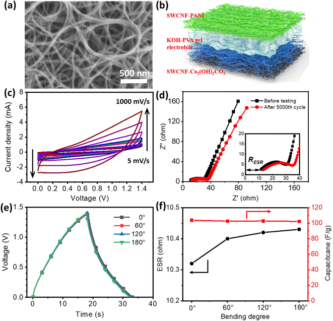
For the construction of flexible SCs with a higher working potential, the hybrid SC strategy was adopted. The negative electrodes were prepared by in situ chemical oxidation polymerization of aniline on the surface of the SWCNTs (Fig. S14, ESI†). Fig. 6a, S15 and S16 (ESI†) show the SEM, TEM and optical images of the SWCNF–PANI hybrid. It can be seen that SWCNTs are covered with a uniform PANI layer, displaying a typical core–shell structure. Fig. S17 (ESI†) provides the Raman spectrum of such a hybrid material. The π–π stacking between PANI and SWCNTs could greatly increase the electrical conductivity and improve the capacitive properties of the entire electrode. The CV curves and rate capability of the SWCNF–PANI negative electrode are shown in Fig. S18 (ESI†); the calculated specific capacitance is 292 F g−1.
The solid-state flexible SWCNF–Co2(OH)2CO3//SWCNF–PANI SCs were assembled with a classical sandwich structure. The detailed configuration of a FSSC device is schematically demonstrated in Fig. 6b. According to the previous CV results, it is confirmed that SWCNF–Co2(OH)2CO3 and SWCNF–PANI electrodes have stable potential windows of 0–0.4 V and −1.0 to 0 V, respectively. Therefore, the operating voltage of the designed hybrid device is expected to extend up to 1.4 V. The mass of the positive and negative electrodes was balanced based on the charge-balance theory.48,49 CV tests of the as-fabricated device at different scan rates are shown in Fig. 6c, all curves exhibit a quasi-rectangular shape even at a high scan rate of 1000 mV s−1, indicating a capacitive behavior and exceptional rate capability of the FSSCs. The GCD curves and corresponding specific capacitances at various current densities are illustrated in Fig. S19 (ESI†). As the current densities increase from 1 A g−1 to 25 A g−1, a high capacitance retention of 63.4% is acquired. Fig. S20 (ESI†) displays the Ragone plots of the FSSC, and it shows a maximum energy density of 28.6 W h kg−1 at a power density of 311.9 W g−1, superior to many reported results. Electrochemical stability of the as-synthesized FSSCs was investigated under a repeating continuous CV test at a scan rate of 200 mV s−1 for 5000 cycles (Fig. S21, ESI†). An overall specific capacitance retention of ∼83.8% is achieved. Besides, the FSSCs show the desired cycling stability under different bending conditions (Fig. S22, ESI†). The Nyquist impedance spectrum of the hybrid FSSCs (Fig. 6d) features a vertical line parallel to the Z′′ axis in the low-frequency region, indicating the fast diffusion process of electrolyte ions into the active materials. In the high frequency range, the intercept of the plots at the Z′ axis is related to the equivalent series resistance (RESR) of the device, which comprises the ionic resistance of the electrolyte, the inherent resistance of the electrode materials, and the contact resistance at the electrode/electrolyte interface. The EIS plots after the 5000th cycle present a similar geometry with the curve before testing, suggesting that the hybrid FSSCs have a relatively good cycling stability. The slightly increasing value of RESR (from 10.3 Ω to 12.1 Ω) during the cycling process may be attributed to the dehydration of the gel electrolyte.
The influence of bending deformations on capacitive performances is examined and illustrated in Fig. 6e. When bending angles increase from 0°, 60°, 120° toward 180°, minimal changes are observed in the charge/discharge curves. The bent device at 180° is able to retain 98% of its initial capacitance, as shown in Fig. 6f. The RESR values under different bending angles were calculated according to the voltage drop in the discharging process. As shown in Fig. 6f, the hybrid FSSCs display an RESR value of 10.32 Ω in the normal state, agreeing well with the EIS result. No obvious increase in the RESR is discovered under bent states.
Conclusions
Free-standing SWCNFs are prepared using FCCVD, and exhibit light weight, high electrical conductivity, excellent mechanical strength, and 3D interconnected porous architecture. As current collectors for FSSCs, SWCNFs demonstrate a high loading efficiency of 75%, a large specific capacitance of 408.4 F g−1 at 1 A g−1, and long-term durability with a capacitance retention of 90.7% after 5000 cycles. These performances dramatically surpass those of the common current collectors such as nickel foam and carbon cloth. In addition, the hybrid SWCNF–Co2(OH)2CO3//SWCNF–PANI FSSCs exhibit excellent capacitive stability and withstand various bending deformations. We expect that this work will open up opportunities for free-standing SWCNFs as current collectors for flexible energy storage devices.Conflicts of interest
There are no conflicts to declare.Acknowledgements
This work was supported by the National Natural Science Foundation of China (22120102004, U21A6004, and 22201014), Shenzhen KQTD Project (KQTD20180411143400981), Science and Technology Major Project of Shanxi (No. 202101030201022), and Beijing National Laboratory for Molecular Sciences (BNLMS-CXTD-202001).Notes and references
- P. Huang, C. Lethien, S. Pinaud, K. Brousse, R. Laloo, V. Turq, M. Respaud, A. Demortiere, B. Daffos and P.-L. Taberna, Science, 2016, 351, 691–695 CrossRef CAS PubMed
.
- J. Ni and L. Li, Adv. Funct. Mater., 2018, 28, 1704880 CrossRef
.
- Y. Zhao, Q. Fang, X. Zhu, L. Xue, M. Ni, C. Qiu, H. Huang, S. Sun, S. Li and H. Xia, J. Mater. Chem. A, 2020, 8, 8969–8978 RSC
.
- H. Li, Z. Tang, Z. Liu and C. Zhi, Joule, 2019, 3, 613–619 CrossRef
.
- S. Zhu, J. Sheng, Y. Chen, J. Ni and Y. Li, Natl. Sci. Rev., 2021, 8, nwaa261 CrossRef CAS PubMed
.
- S. Sun, T. Zhai, C. Liang, S. V. Savilov and H. Xia, Nano Energy, 2018, 45, 390–397 CrossRef CAS
.
- S. Zhu, J. Ni and Y. Li, Nano Res., 2020, 13, 1825–1841 CrossRef CAS
.
- X. Zhang, C. Jiang, J. Liang and W. Wu, J. Mater. Chem. A, 2021, 9, 8099–8128 RSC
.
- X. Peng, L. Peng, C. Wu and Y. Xie, Chem. Soc. Rev., 2014, 43, 3303–3323 RSC
.
- P. Xie, W. Yuan, X. Liu, Y. Peng, Y. Yin, Y. Li and Z. Wu, Energy Storage Mater., 2021, 36, 56–76 CrossRef
.
- M. Fu, Z. Zhu, W. Chen, H. Yu and R. Lv, Carbon, 2022, 199, 520–528 CrossRef CAS
.
- H. Li, R. Chen, M. Ali, H. Lee and M. J. Ko, Adv. Funct. Mater., 2020, 30, 2002739 CrossRef CAS
.
- P. Liu, J. Yan, Z. Guang, Y. Huang, X. Li and W. Huang, J. Power Sources, 2019, 424, 108–130 CrossRef CAS
.
- M. Notarianni, J. Liu, F. Mirri, M. Pasquali and N. Motta, Nanotechnology, 2014, 25, 435405 CrossRef PubMed
.
- A. Abdisattar, M. Yeleuov, C. Daulbayev, K. Askaruly, A. Tolynbekov, A. Taurbekov and N. Prikhodko, Electrochem. Commun., 2022, 142, 107373 CrossRef CAS
.
- J. Yu, C. Yu, W. Guo, Z. Wang, Y. Ding, Y. Xie, K. Liu, H. Wang, X. Tan and H. Huang, Adv. Funct. Mater., 2022, 32, 2204609 CrossRef CAS
.
- M. Wang, M. Tang, S. Chen, H. Ci, K. Wang, L. Shi, L. Lin, H. Ren, J. Shan and P. Gao, Adv. Mater., 2017, 29, 1703882 CrossRef PubMed
.
- X. Xiong, D. Ding, D. Chen, G. Waller, Y. Bu, Z. Wang and M. Liu, Nano Energy, 2015, 11, 154–161 CrossRef CAS
.
- Y. J. Yang, J. Dong, C. Zhang, X. Ding, Y. Li, H. Ren and F. Guo, J. Electroanal. Chem., 2021, 895, 115537 CrossRef CAS
.
- J. Cheng, H. Yan, Y. Lu, K. Qiu, X. Hou, J. Xu, L. Han, X. Liu, J.-K. Kim and Y. Luo, J. Mater. Chem. A, 2015, 3, 9769–9776 RSC
.
- J. Wang, M. Wang, F. Chen, Y. Li, L. Zhang, Y. Zhao and C. Chen, Energy Storage Mater., 2021, 34, 22–27 CrossRef
.
- H. Liang, J. Lin, H. Jia, S. Chen, J. Qi, J. Cao, T. Lin, W. Fei and J. Feng, J. Mater. Chem. A, 2018, 6, 15040–15046 RSC
.
- L. Wang, H. Yang, X. Liu, R. Zeng, M. Li, Y. Huang and X. Hu, Angew. Chem., Int. Ed., 2017, 56, 1105–1110 CrossRef CAS PubMed
.
- J. Xu, Q. Wang, X. Wang, Q. Xiang, B. Liang, D. Chen and G. Shen, ACS Nano, 2013, 7, 5453–5462 CrossRef CAS PubMed
.
- L.-F. Chen, Z.-Y. Yu, J.-J. Wang, Q.-X. Li, Z.-Q. Tan, Y.-W. Zhu and S.-H. Yu, Nano Energy, 2015, 11, 119–128 CrossRef CAS
.
- Z. Ye, T. Li, G. Ma, X. Peng and J. Zhao, J. Power Sources, 2017, 351, 51–57 CrossRef CAS
.
- K. Wang, S. Luo, Y. Wu, X. He, F. Zhao, J. Wang, K. Jiang and S. Fan, Adv. Funct. Mater., 2013, 23, 846–853 CrossRef CAS
.
- Z. Zhou, N. Li, Y. Yang, H. Chen, S. Jiao, W. L. Song and D. Fang, Adv. Energy Mater., 2018, 8, 1801439 CrossRef
.
- D. A. Dikin, S. Stankovich, E. J. Zimney, R. D. Piner, G. H. Dommett, G. Evmenenko, S. T. Nguyen and R. S. Ruoff, Nature, 2007, 448, 457 CrossRef CAS PubMed
.
- S. Seiler, C. E. Halbig, F. Grote, P. Rietsch, F. Börrnert, U. Kaiser, B. Meyer and S. Eigler, Nat. Commun., 2018, 9, 836 CrossRef PubMed
.
- A. Beltram, M. Melchionna, T. Montini, L. Nasi, R. Gorte, M. Prato and P. Fornasiero, Catal. Today, 2015, 253, 142–148 CrossRef CAS
.
- Y. Li, H. Li, A. Petz and S. Kunsági-Máté, Carbon, 2015, 93, 515–522 CrossRef CAS
.
- S. H. Lee, C. Park, J. W. Park, S. J. Kim, S. S. Im and H. Ahn, J. Power Sources, 2019, 414, 460–469 CrossRef CAS
.
- S. Zhu, Z. Wang, F. Huang, H. Zhang and S. Li, J. Mater. Chem. A, 2017, 5, 9960–9969 RSC
.
- Q. Guo, J. Yuan, Y. Tang, C. Song and D. Wang, Electrochim. Acta, 2021, 367, 137525 CrossRef CAS
.
- S. Zhu, Y. Chang, W. Hou, Y. Li, J. Ni and G. Han, Carbon, 2022, 200, 75–83 CrossRef CAS
.
- Y. Xu, Z. Lin, X. Zhong, X. Huang, N. O. Weiss, Y. Huang and X. Duan, Nat. Commun., 2014, 5, 4554 CrossRef CAS PubMed
.
- H. Kataura, Y. Kumazawa, Y. Maniwa, I. Umezu, S. Suzuki, Y. Ohtsuka and Y. Achiba, Synth. Met., 1999, 103, 2555–2558 CrossRef CAS
.
- S. Jiang, P.-X. Hou, M.-L. Chen, B.-W. Wang, D.-M. Sun, D.-M. Tang, Q. Jin, Q.-X. Guo, D.-D. Zhang and J.-H. Du, Sci. Adv., 2018, 4, eaap9264 CrossRef PubMed
.
- S. Zhu, Z. Wang, F. Huang, H. Zhang and S. Li, J. Mater. Chem. A, 2017, 5, 9960–9969 RSC
.
- E. H. Nickel and L. G. Berry, Can. Mineral., 1981, 19, 315–324 CAS
.
- J. Yang, C. Yu, X. Fan, C. Zhao and J. Qiu, Adv. Funct. Mater., 2015, 25, 2109–2116 CrossRef CAS
.
- Z. Gao, Z. Wang, J. Chang, L. Chen, D. Wu, F. Xu, X. Wang and K. Jiang, J. Colloid Interface Sci., 2019, 534, 563–573 CrossRef CAS PubMed
.
- X. Zhou, Y. Zhong, M. Yang, Q. Zhang, J. Wei and Z. Zhou, ACS Appl. Mater. Interfaces, 2015, 7, 12022–12029 CrossRef CAS PubMed
.
- P. Shen, Z. Wang, C. Yang, L. Zhao, T. Liu, M. Shen, J. Li and D. Qian, Electrochim. Acta, 2018, 283, 1568–1577 CrossRef CAS
.
- S. Chen, Q. Wu, M. Wen, C. Wang, Q. Wu, J. Wen, M. Zhu and Y. Wang, J. Phys. Chem. C, 2017, 121, 9719–9728 CrossRef CAS
.
- K. Xu, R. Zou, W. Li, Q. Liu, X. Liu, L. An and J. Hu, J. Mater. Chem. A, 2014, 2, 10090–10097 RSC
.
- J. Ma, J. Xia, Z. Liang, X. Chen, Y. Du and C.-H. Yan, Small, 2021, 17, 2104423 CrossRef CAS PubMed
.
- Y. Jiang, J. Li, Z. Jiang, M. Shi, R. Sheng, Z. Liu, S. Zhang, Y. Cao, T. Wei and Z. Fan, Carbon, 2021, 175, 281–288 CrossRef CAS
.
Footnote |
| † Electronic supplementary information (ESI) available. See DOI: https://doi.org/10.1039/d2ta09396k |
| This journal is © The Royal Society of Chemistry 2023 |

