
Boosting the performance and stability of inverted perovskite solar cells by using a carbolong derivative to modulate the cathode interface†
Jinhua
Li‡
ab,
Jiantao
Wang‡
 c,
Yecheng
Zhou‡
d,
Chengzhuo
Yu
c,
Heng
Liu
c,
Xingnan
Qi
c,
Ruxue
Li
e,
Yuhui
Hua
ab,
Yinye
Yu
d,
Rui
Chen
e,
Dafa
Chen
a,
Lingling
Mao
a,
Haiping
Xia
*ab and
Hsing-Lin
Wang
*cf
c,
Yecheng
Zhou‡
d,
Chengzhuo
Yu
c,
Heng
Liu
c,
Xingnan
Qi
c,
Ruxue
Li
e,
Yuhui
Hua
ab,
Yinye
Yu
d,
Rui
Chen
e,
Dafa
Chen
a,
Lingling
Mao
a,
Haiping
Xia
*ab and
Hsing-Lin
Wang
*cf
aDepartment of Chemistry, Shenzhen Grubbs Institute, Southern University of Science and Technology, Xueyuan Avenue 1088, Shenzhen 518055, China. E-mail: xiahp@sustech.edu.cn
bDepartment of Chemistry, College of Chemistry and Chemical Engineering, Xiamen University, Xiamen 361005, China
cDepartment of Materials Science and Engineering, Southern University of Science and Technology, Xueyuan Avenue 1088, Shenzhen 518055, China. E-mail: wangxl3@sustech.edu.cn
dSchool of Materials Science and Engineering, Sun Yat-sen University, Zhongshan West Road 135, Guangzhou 510275, China
eDepartment of Electrical and Electronic Engineering, Southern University of Science and Technology, Xueyuan Avenue 1088, Shenzhen 518055, China
fGuangdong Provincial Key Laboratory of Energy Materials for Electric Power, Southern University of Science and Technology, Xueyuan Avenue 1088, Shenzhen 518055, China
First published on 13th July 2022
Abstract
Perovskite solar cells (PSCs) require low work function (WF) cathodes to collect electrons, but often chemically reactive metals are used for devices with inverted configuration. Reactive metals (such as Ag, Cu and Al) with low WF encounter easy oxidation and corrosion, which threatens the long-term stability of devices. Herein, we tailor an organometallic carbolong derivative to modulate the cathode interface in inverted PSCs for the enhancement of power conversion efficiency (PCE) and stability. Density functional theory and surface WF characterization reveal that this organometallic compound can reduce the WF of metals by forming interfacial and molecular dipoles, which reduce the energy barrier for electron transport from the electron transport layer to the external metal cathode. By using this carbolong derivative to modulate the cathode interface, inverted PSCs based on the commonly used Ag cathode obtain a PCE of 21.46% with a remarkable FF of 83.14%. By replacing low-WF Ag with high WF Au, the devices achieve more than 20% PCE and improved ambient stability, and can maintain over 85% of the initial PCE for over 500 h in an inert environment under the maximum power point (MPP) tracking. This work provides a significant route for the realization of high-efficiency and stable PSCs by integrating rationally designed cathode interfacial materials and chemically stable metals.
Introduction
Perovskite solar cells (PSCs) can be solution-processed and have achieved over 25% power conversion efficiency (PCE), which enable them to be an extremely competitive candidate in the new-generation photovoltaic sphere.1–5 PSCs with inverted configuration possess advantages of low-temperature processability and long device stability, and they can be integrated into tandem devices to further push the PCE promisingly over the S–Q limit.6,7 The main body of inverted PSCs is a sandwich structure (hole transporting layer (HTL)/perovskite absorber/electron transporting layer (ETL)) processed between a transparent conductive oxide (TCO) and an external metal cathode that requires a low work-function (WF).8 However, the low WF cathode commonly uses reactive metals, such as silver (Ag), copper (Cu) and aluminum (Al), which are chemically unstable due to their character of being easily oxidized by air, which severely threatens the long-term stability of the inverted devices.9In general, a cathode interlayer (CIL) is introduced between the ETL and the cathode metal to modulate the interfacial energy barrier and facilitate the carrier transport.10,11 In addition, a dense and hydrophobic CIL spacer is efficacious to protect the underneath layers from metal electrode diffusion and moisture penetration.12,13 One alternative approach to achieve a long-lived cathode is to design CIL materials that can both modify the interfaces and allow the use of chemically stable metals.14 For example, Fang et al. reported a benzotriazole CIL to form a protective layer by suppressing the reaction between the degraded perovskite and Cu electrode.9 Li and Yang et al. reported the use of a phenyl phosphine-inlaid semiconducting polymer as the CIL in inverted PSCs to attain a simultaneous enhancement of device efficiency and thermal/lighting stability.15 Although the CILs with ample molecular structures have been reported to improve the device performance and stability, the molecular design and employment of novel CIL materials that allow the use of high-WF and chemically stable metals as cathodes are still under explored. Our recent work showed that the utilization of a series of novel organometallics with π-conjugating frameworks (carbolong complexes16) can drastically reduce the metal WF and hence achieve high device PCE and superior operational stability for both perovskite solar cells17 and organic solar cells.18,19 Interestingly, the coordination sphere modification of the carbolong framework would improve the device performance. As shown in Fig. 1, the introduction of carbolong complex a1 (M-CCC core), of which the iridium center is chelated by a tridentate carbon–carbon–carbon (CCC) ligand, as the CIL material in inverted PSCs obtained champion PCEs of 20.65% (Ag as the metal cathode) and 18.09% (Au as the metal cathode).17 Furthermore, when the modified framework b1 (M-CCO core) was employed as the CIL, the device performance, especially for the high work-function Au cathode, was enhanced significantly.17 The remarkable improvement of efficiencies in PSCs by using distinct organometallic frameworks as interfacial materials prompts us to consider whether the rational design of the carbolong framework is still applicable to modulate the interfacial properties of the cathode in inverted PSCs, thus boosting the device PCE.
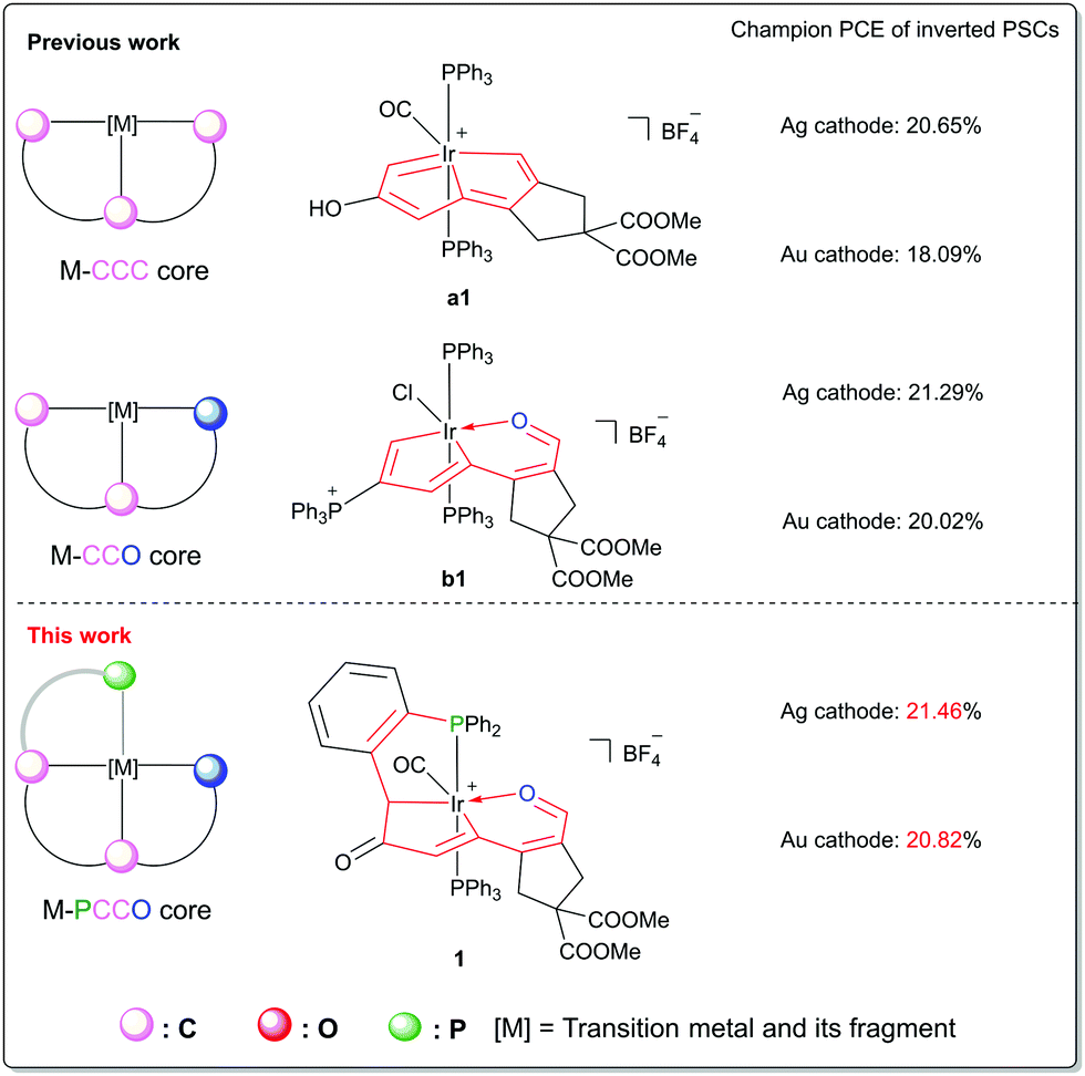 | ||
| Fig. 1 Modification of the carbolong framework and the device performance results achieved by their usage as CILs combining both low-WF Ag and high-WF Au cathodes in inverted PSCs. | ||
Herein, we report the irida-carbolong derivative 1 that exhibits a brand-new organometallic framework as the CIL in inverted PSCs to enhance the device performance and stability. This material can extensively reduce the WF of external metals in inverted PSCs by forming interfacial molecular dipoles. Hence, the employment of compound 1 as the CIL in inverted PSCs reduces the energy barrier for electron transport from the ETL to the external metal, which facilitates the fill factor (FF) and current density (Jsc). The inverted PSCs based on the Ag cathode obtain a champion PCE of 21.46% with a remarkable FF of 83.14%. As a proof of concept, we replaced the low-WF Ag with high WF Au as the cathode for the fabrication of high performance and stable inverted PSCs. The devices based on the Au cathode with the CIL achieve more than 20% PCE and can maintain over 85% of the initial PCE for over 500 h in an inert environment under the maximum power point (MPP) tracking. This work establishes a route for the achievement of high performance and stable PSCs by combining the rationally designed CIL material with the chemically stable metal.
Experimental methods
Synthesis and characterization of the irida-carbolong derivative 1
To a mixture of a1 (160 mg, 0.15 mmol) and 3-chloroperbenzoic acid (129 mg, 0.75 mmol) was added dichloromethane (10 mL). The mixture was then stirred at room temperature for 30 min to give a yellow green solution. After the completion of the reaction, the solution was evaporated under vacuum to a volume of approximately 2 mL. Addition of diethyl ether (20 mL) produced a yellowish precipitate, which was collected and washed with diethyl ether (3 × 20 mL) and dried under vacuum to give compound 1 as a yellow solid. Yield: 130 mg, 80%. 1H NMR (400 MHz, CD2Cl2, δ): 9.16 (s, 1H, C7H), 6.32 (t, J(PH) = 3.0 Hz, 1H, C3H), 7.93–6.85 (m, 29H, Ph), 4.20 (d, J(PH) = 5.2 Hz, 1H, C1H), 3.76 (s, 3H, COOCH3), 3.73 (s, 3H, COOCH3), 3.12 (d, J(HH) = 5.1 Hz, 1H, C11H), 3.11 (d, apparent br, 1H, C11H), 2.95 (d, J(HH) = 18.6 Hz, 1H, C9H), 2.38 ppm (d, J(HH) = 18.6 Hz, 1H, C9H); 31P{1H} NMR (161.9 MHz, CD2Cl2, δ): 15.00 (d, J(PP) = 316.6 Hz, IrPPh3), −2.31 ppm (d, J(PP) = 316.6 Hz, IrPPh3); 13C{1H} NMR (100.6 MHz, CD2Cl2, plus 13C-dept 135, 1H–13C HSQC and 1H–13C HMBC, δ): 209.3 (d, J(PP) = 2.9 Hz, C2), 193.9 (s, C7), 174.4 (t, J(PC) = 8.7 Hz, C8), 170.9 (s, COOMe), 170.1 (s, COOMe), 166.4 (t, J(PC) = 9.9 Hz, C6), 156.5 (dd, J(PC) = 27.1 Hz, J(PC) = 4.0 Hz, C4), 155.3 (s, C12), 143.0 (t, J(PC) = 5.2 Hz C3), 138.1-126.1 (m, Ph), 55.8 (s, C10), 53.6 (s, COOCH3), 41.7 (s, C9), 40.4 (s, C11), 38.9 ppm (d, J(PC) = 2.0 Hz, C1); HRMS (ESI) m/z: calcd for [C51H42IrO7P2]+,1021.2030; found, 1021.2065. CCDC 2133382 contains the supplementary crystallographic data of compound 1 for this paper.†Material and solution preparation for PSC fabrication
FAI (216.68 mg), PbI2 (626.97 mg), MABr (15.68 mg), and PbBr2 (51.38 mg) were weighed in a vial in a glovebox. To them was added 1 mL of mixed solvent of DMF and DMSO in a volume ratio (v/v) of 4/1. The solution was stirred at 65 °C for 60 minutes, and to it was added 40 μL of the CsI solution (519.62 mg CsI dissolved in 1 mL of DMSO). The mixed precursor was stirred at 65 °C for 15 min before use. PTAA solution was prepared by dissolving 6 mg of PTAA into 2 mL of CB and stirring for 1 h. PC61BM solution was prepared by weighing 30 mg of PC61BM into 1.5 mL of CB and stirring at 70 °C for 2 h.Fabrication of inverted PSCs
ITO glass was cleaned using detergent, acetone and isopropanol under sonication for 20 minutes respectively. The ITO glass was dried with nitrogen and treated by air plasma for 4 minutes before transferring into a glove box for further spin-coating procedures. PTAA was spin-coated at 6000 rpm for 30 s and annealed at 100 °C for 10 minutes. The perovskite precursor was deposited by spin-coating at 1000 rpm for 10 s and then 5000 rpm for 30 s. 250 μL of CB were splashed at 8 s before the end of the high-speed step. The substrate was immediately annealed at 100 °C for 20 min. PC61BM was spin-coated on the perovskite layer at 1000 rpm for 45 s. Ethanol solution with or without compound 1 was spin-coated at 5000 rpm for 60 s. 100 nm Ag or 80 nm Au was deposited in the thermal evaporator. The device area of 0.04 cm2 is defined by the overlap of the ITO and metal electrode.Characterization
The absorbance spectra of solutions and films were recorded using a UV-Vis spectrophotometer (Agilent Cary 5000). The film surface morphology was detected using scanning electron microscopy (SEM, ZEISS Merlin). The film surface topography and surface potential were recorded by atomic force microscopy (AFM, Asylum Research MFP-3D-Stand Alone) under the electric mode of scanning Kelvin probe microscopy (SKPM). Ultraviolet photoelectron spectroscopy (UPS) was performed with a non-monochromated He Iα photon source (hν = 21.22 eV) to detect the work function of the metals with or without the deposition of the carbolong-derived compound. A source meter (Keysight B2901A) and a solar simulator (Enlitech SS-F5-3A) were used to measure the current density–voltage (J–V) curves. The device J–V curves were measured with 10 mV intervals and 10 ms delay time under AM 1.5 G at 100 mW cm−2 light intensity illumination. The external quantum efficiency (EQE) spectra were recorded with a quantum efficiency measuring facility (Enlitech QER-3011), in which the light intensity at every measured wavelength was calibrated with a standard silicon photodiode. Maximum-power-point (MPP) outputs were collected by measuring the steady-state current density at the MPP voltage in an inert environment. All the above device measurements were performed in a nitrogen filled glove box. Transient photocurrent (TPC) measurements were carried out with a self-build system, where the solar cells were excited using a 532 nm incident laser (SpitLight Compact IOO) and a digital oscilloscope (Keysight) was used to record the photocurrent decay signal of the sample. Time-resolved photoluminescence (TRPL) spectra were recorded using a fluorescence spectrometer (Fluo Time 300) with the incident light intensity of one sun. Electrochemical impedance spectroscopy (EIS) was performed in the frequency range from 200 Hz to 2 MHz using the electrochemical workstation (Princeton Applied Research, P4000+) under illumination conditions at the open-circuit voltage.Results and discussion
As illustrated in Fig. 2(A), we designed and synthesized the irida-carbolong derivative 1 by treatment of the reported irida-carbolong a117 with 3-chloroperbenzoic acid (m-CPBA) at room temperature (RT), and it was obtained as a yellow solid in 80% yield. The identity of compound 1 was characterized by nuclear magnetic resonance (NMR) spectroscopy and high-resolution mass spectrometry (see the ESI,† Fig. S1–S4 for details). The solid structure of compound 1 was also determined by single-crystal X-ray diffraction as depicted in Fig. 2(B), which clearly shows its ionic character and the existence of a [BF4]− counter anion. Interestingly, the iridium center is chelated by a tetradentate phosphorus–carbon–carbon–oxygen (PCCO) ligand, which indicates the carbon–carbon coupling between C1 and one of the phenyl carbons in the PPh3 ligand. We calculated the highest occupied molecular orbital (HOMO) and the lowest unoccupied molecular orbital (LUMO) of the cation of compound 1, which are presented in Fig. 2(C) and (D), respectively. The HOMO is −8.81 eV and the LUMO is −5.74 eV. The UV-Vis absorption of compound 1 in ethanol is shown in Fig. 2(E), which displays broad absorption from the UV to the visible region. According to the UV-Vis absorption, the bandgap of compound 1 was estimated to be 2.08 eV. The thermogravimetric curve of compound 1 is presented in Fig. 2(F). The 5% weight loss temperature (T95) at 206.1 °C suggests its good thermal stability, which is crucial to avoid degradation during the thermal evaporation of the external metal cathode.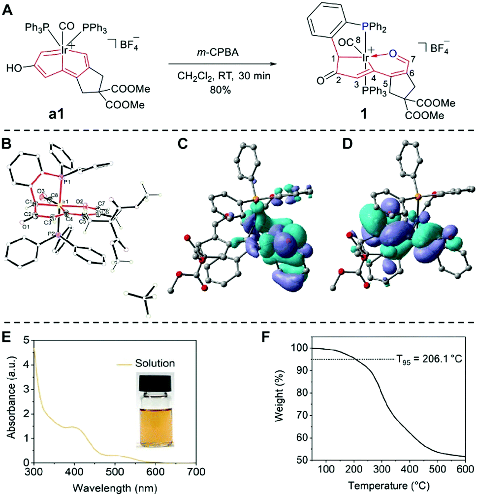 | ||
| Fig. 2 (A) Synthetic route for the target irida-carbolong derivative 1. (B) Single-crystal X-ray diffraction structure of 1 (ellipsoids are at the 50% probability level, and the hydrogen atoms of phenyl groups in PPh3 were omitted for clarity), DFT calculations of the (C) HOMO and (D) LUMO for the cation of compound 1, (E) UV-Vis absorbance, and (F) thermogravimetric curve of compound 1. | ||
To verify the capacity of compound 1 as the CIL in inverted PSCs, we fabricated photovoltaic devices with the structure of ITO/PTAA/perovskite/PC61BM/CIL/Ag (Fig. 3(A)).20 All the layers except for the electrodes are solution processed, which is low-cost and straightforward.21 The perovskite composition is (CsPbI3)0.05[(FAPbI3)0.9(MAPbBr3)0.1], whose related characterization including surface SEM morphology (Fig. S5, ESI†), film XRD (Fig. S6, ESI†), UV-Vis absorption and PL curves (Fig. S7, ESI†) can be found in the ESI.† We recorded the J–V curves with the forward scan and reverse scan of the champion devices without and with the CIL as shown in Fig. 3(B) and (C), respectively. Their detailed photovoltaic parameters are listed in Table S1 (ESI†). The pristine device without the CIL presents a highest PCE of 17.39%, with an open-circuit voltage (Voc) of 1.08 V, a short-circuit current density (Jsc) of 22.79 mA cm−2, and a fill factor (FF) of 70.38%. The optimized concentration of compound 1 is 0.8 mg mL−1, which enables a film with 8 nm thickness as measured using a spectroscopic ellipsometer. Under this optimal condition, the champion device with compound 1 as the CIL delivers a highest PCE of 21.46%, with a Voc of 1.08 V, a Jsc of 23.88 mA cm−2, and a FF of 83.14%. In comparison, the effects of CIL thickness on the device performance were also taken into consideration as shown in Table S2 (ESI†), which clearly shows that the thickness of 8 nm is the best. To show the superiority of the irida-carbolong derivative 1 of this work to the other cathode interlayers, we fabricated the PSCs with the widely-used bathocuproine (BCP) as the CIL. The photovoltaic parameters of the 8 nm BCP based device are also included in Table S1 (ESI†). The PSCs with BCP possess a highest PCE of 19.02%, with a Voc of 1.07 V, a Jsc of 21.57 mA cm−2, and a FF of 82.40%, still lower than our compound 1 based device. In addition, we compared our results with the reported literature as listed in Table S3 (ESI†). The performances of our CIL included devices are among the highest reported values for inverted PSCs without passivation processing. The EQE values of both devices with and without compound 1 are shown in Fig. 3(D). After inserting the CIL, the device presents an enhanced EQE compared with the pristine device at every measured wavelength. The integrated Jsc of the pristine device is 21.09 mA cm−2 while that of the CIL-modified device is 22.12 mA cm−2. The calculated Jsc values of the pristine device and the CIL-modified device show 7.46% and 7.37% difference with those measured from J–V curves. To confirm the PCE under stabilized conditions, we measured the maximum-power-point (MPP) outputs of typical devices with and without the CIL, and the results are plotted in Fig. 3(E). The MPP outputs within 600 s under AM 1.5G one sun illumination give a stabilized device PCE of 19.5% for the CIL-modified device and 15% for the pristine device. To investigate the device reproducibility, the PCE values of pristine and CIL-modified devices with a respective total number of 20 were statistically studied and their distributions are presented in Fig. 3(F). The average PCE values with standard deviation of the pristine and CIL-modified devices are 15.21 ± 1.42% and 19.61 ± 0.9%, respectively, which are highly in line with the J–V and MPP measurements. Therefore, compound 1 as the CIL plays an important role in enhancing the device performance.
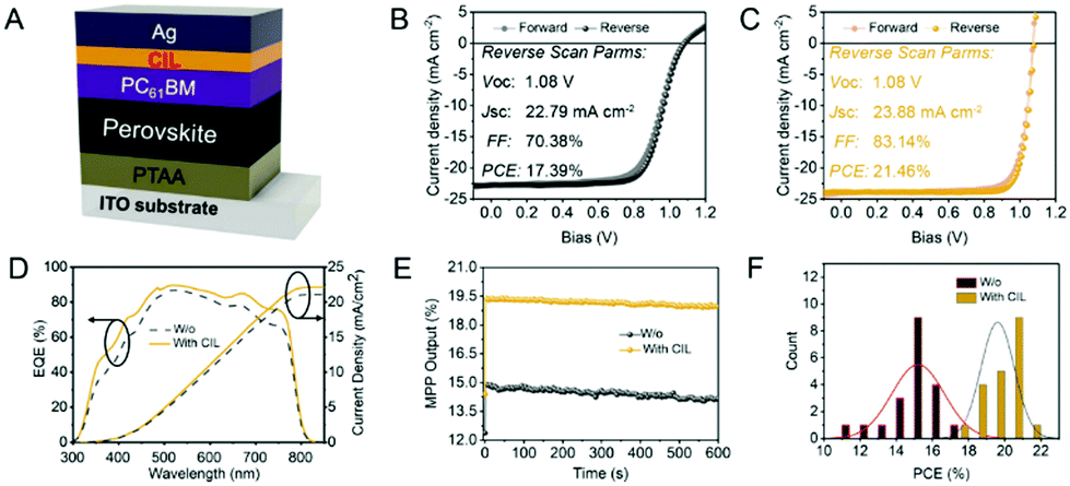 | ||
| Fig. 3 (A) Device structure. J–V curves of the best device (B) without and (C) with the CIL. (D) EQE and calculated Jsc curves. (E) MPP output. (F) Device statistics. | ||
From the analysis of device performance, the employment of compound 1 as the CIL mainly boosts the FF and Jsc, which are highly related to the carrier transport efficiency. Generally, a low-WF metal has a lower interfacial energy barrier relative to the ETL and can improve the carrier transport. The introduction of compound 1 as the CIL was expected to reduce the WF of the Ag surface since we have confirmed that the WF of PCBM is almost not impacted by the CIL as shown in Fig. S8 (ESI†), despite the efficient reduction of the PCBM surface roughness (Fig. S9, ESI†). To verify the WF reduction of metal Ag enabled by the introduction of compound 1, we first conducted the density functional theory (DFT) study via building the adsorption model with different molecular configurations and performed molecular dynamics simulation to obtain the final configuration as shown in Fig. S10 (ESI†). In the final molecular adsorption configuration with the lowest energy as shown in Fig. 4(A), [BF4]− anion tends to adsorb on the Ag surface and thus the organometallic cation is sterically distributed on the anion surface, leading to the formation of the anion–cation molecular dipole (μ1). In addition, the cation in compound 1 is large enough to cover the [BF4]− anion, and parts of the cations prefer to contact with the Ag surface directly, contributing to another interfacial dipole (μ2) on the Ag surface. Both the molecular dipole (μ1) and interfacial dipole (μ2) would synergistically help increase the inner surface potential and reduce the WF of Ag.22 The local potential curve derived from the adsorption model is shown in Fig. 4(B). The WF of the Ag (111) surface is obviously reduced from 4.3 eV to 3.95 eV, which is a 0.35 eV reduction.
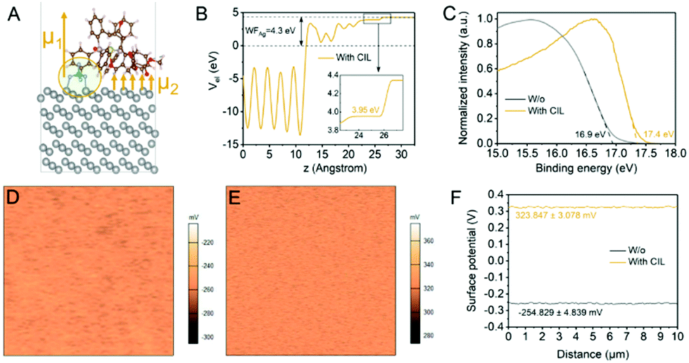 | ||
| Fig. 4 (A) Molecular configuration with the lowest binding energy on the Ag (111) surface and (B) localized potential curve of compound 1 adsorbed on the Ag surface. (C) UPS curves of Ag surfaces with and without the coverage of the CIL. SKPM mapping of metal surfaces (D) before and (E) after the deposition of the CIL and their (F) linecut profiles. | ||
To experimentally confirm the WF reduction of the Ag surface after using compound 1 as the CIL, we carried out the UPS measurements. The WF can be calculated according to the equation WF = hϑ − Ecut-off, where hϑ is the incident photon energy of 21.2 eV, and Ecut-off is the energy of the secondary electron cut-off. The WF of the Ag surface shows a 0.5 eV reduction after CIL modification according to the energy of the secondary electron cut-off as shown in Fig. 4(C). Moreover, we further characterized the WF change before and after the coverage of compound 1 on the Ag surface by performing scanning Kelvin probe microscopy (SKPM). As shown in Fig. 4(D) and (E), the surface potential mappings of Ag surfaces before and after the deposition of the CIL reveal a noticeable increase. From the comparison of their extracted line-cut profiles as shown in Fig. 4(F), the surface potential is increased from −254.829 mV to 323.847 mV. According to the equation φM = φtip − eVcp, where φM and φtip refer to the WF of the metal and conductive tip, respectively, e is the charge constant, and Vcp is the contact potential, the change of measured surface potentials before and after the introduction of the CIL reflects a WF reduction of approximately 0.59 eV after introducing compound 1.23
To clarify how the dipoles generated by the CIL affect the metal electrode work function, a schematic diagram of the energy level and dipole distribution is plotted in Fig. 5(A). Due to the CIL dipole layer at the interface of PC61BM and the metal cathode, the vacuum energy level (Evac) is steeply shifted, and it therefore reduces the apparent WF of the metal cathode by Δ.24 This electric dipole interlayer can strongly affect the carrier transport when embodied into photovoltaic devices. To study the carrier transport at the cathode interface in the perovskite-included devices, we collected the transient photocurrent (TPC) decay profiles of the PSCs with and without the CIL. As shown in Fig. 5(B), the device without the CIL has a longer photocurrent decay life time of 0.43 μs, longer than the CIL modified device of 0.19 μs. The shorter lifetime after the usage of the CIL signifies the enhanced carrier extracted to the electrodes in the CIL modified PSCs.25 We further performed time-resolved photoluminescence (TRPL) to characterize the carrier transport dynamics in the PSCs with and without the CIL as presented in Fig. 5(C). The fast extraction of carriers to the electrode would result in less carrier recombination and a shorter TRPL lifetime. The decay spectra were fitted with a bi-exponential function I(t) = A1![[thin space (1/6-em)]](https://www.rsc.org/images/entities/char_2009.gif) exp(−t/τ1) + A2exp(−t/τ2), where τ1 is a fast component and τ2 is a slow component. The fitting parameters are listed in Table S4 (ESI†). The PSCs with the CIL have a shorter average decay lifetime τav (τav = A1τ1 + A2τ2), which indicates a facilitated carrier transport compared with the pristine device without the CIL. Much higher carrier transport should result in less interfacial carrier recombination induced by carrier accumulation in PSCs, which were further characterized by EIS. The EIS Nyquist plots of PSCs with and without the CIL are shown in Fig. 5(D). According to the inset equivalent circuit, the EIS resistances mainly contain a transport resistance (Rc) and a recombination resistance (Rrec). A larger semicircle of the PSCs with the CIL corresponds to a larger Rrec, which indicates the inhibited carrier recombination in the devices with the CIL.25 Therefore, the reduction of the Ag WF enabled by the CIL leads to improved carrier transport and suppressed carrier recombination at the ETL/cathode interface, contributing to the much-boosted device FF and Jsc.
exp(−t/τ1) + A2exp(−t/τ2), where τ1 is a fast component and τ2 is a slow component. The fitting parameters are listed in Table S4 (ESI†). The PSCs with the CIL have a shorter average decay lifetime τav (τav = A1τ1 + A2τ2), which indicates a facilitated carrier transport compared with the pristine device without the CIL. Much higher carrier transport should result in less interfacial carrier recombination induced by carrier accumulation in PSCs, which were further characterized by EIS. The EIS Nyquist plots of PSCs with and without the CIL are shown in Fig. 5(D). According to the inset equivalent circuit, the EIS resistances mainly contain a transport resistance (Rc) and a recombination resistance (Rrec). A larger semicircle of the PSCs with the CIL corresponds to a larger Rrec, which indicates the inhibited carrier recombination in the devices with the CIL.25 Therefore, the reduction of the Ag WF enabled by the CIL leads to improved carrier transport and suppressed carrier recombination at the ETL/cathode interface, contributing to the much-boosted device FF and Jsc.
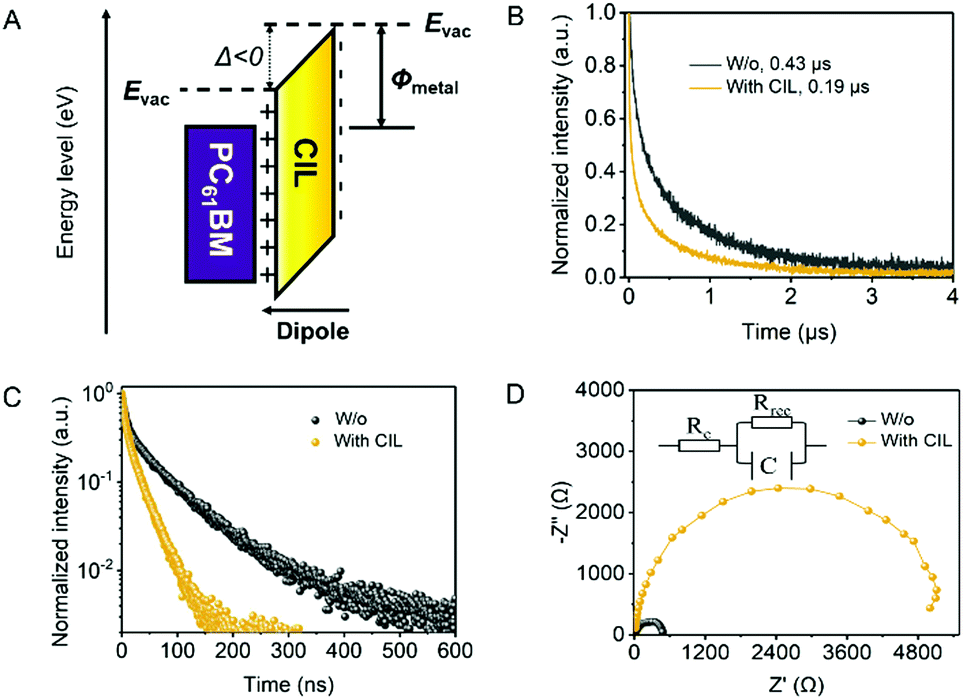 | ||
| Fig. 5 (A) Schematic diagram of the energy level and dipole distribution, (B) TPC, (C) TRPL and (D) EIS curves of the solar cells with and without the CIL. | ||
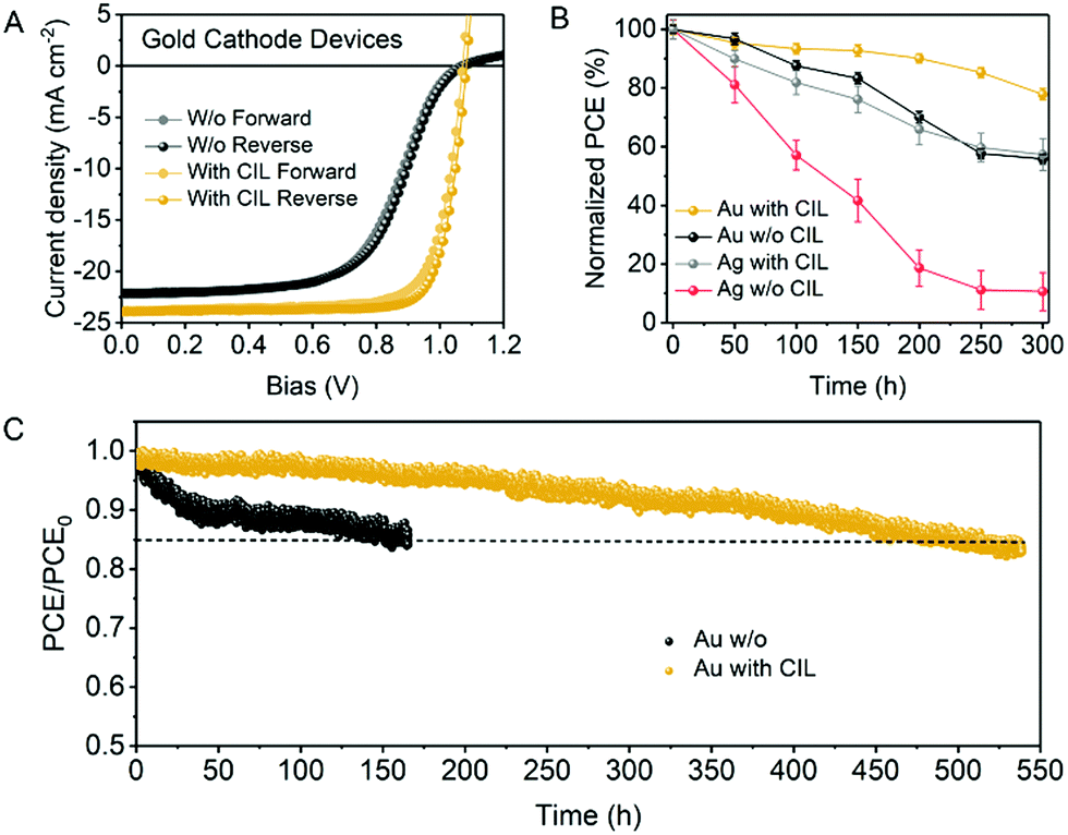
As low-WF metals encounter air-exposure-caused oxidation and halogen-diffusion-induced corrosion, it is promising to replace Ag with other high-WF and chemically stable metals.26 For concept demonstration, we employed high-WF and chemically stable metal gold (Au) as the cathode in the inverted PSCs. The J–V curves of Au based champion devices with and without the CIL are exhibited in Fig. 6(A). The photovoltaic parameters are listed in Table S5 (ESI†). The champion device without the CIL has a Voc of 1.08 V, a Jsc of 22.12 mA cm−2, a FF of 59.33% and a PCE of 14.11% while the device with the CIL has a Voc of 1.08 V, a Jsc of 23.92 mA cm−2, a FF of 80.36% and a PCE of 20.82% under reverse scan conditions. Similar to the Ag based devices, the Au based devices also show boosted FF and Jsc after the introduction of the CIL. Due to the higher WF of Au than Ag, there is a larger energy barrier for electron transport at the PC61BM/Au interface, which leads to worse FF and Jsc. The employment of the CIL can reduce the WF of Au as demonstrated by the SKPM measurements (Fig. S11, ESI†), which results in the facilitated carrier transport at the ETL/cathode interface and improved device FF and Jsc.
 | ||
| Fig. 6 (A) J–V curves of champion PSCs based on the gold cathode with and without the CIL. (B) Environmental stability of six devices based on the gold (Au) cathode and silver (Ag) cathode with and without the CIL, with devices without encapsulation being stored in air and measured in a glovebox. (C) Light stability of PSCs based on the gold cathode with and without the CIL. Devices were measured under MPP tracking in the glove box with continuous white LED light soaking. | ||
For stability measurements, we first measured the change of device efficiencies relative to the initial point under ambient conditions. Unencapsulated devices based on the Au cathode and Ag cathode with and without the CIL were stored in air with a humidity of 55 ± 10%. As shown in Fig. 6(B), within 300 h tracking time, the devices with the CIL present better ambient stability than the devices without the CIL and the Au/CIL devices present the best stability, which can hold over 80% of the initial PCE for more than 250 h. By contrast, the PCE of the Au based device without the CIL decreases to nearly 80% of the initial PCE at around 150 h. In addition, the PCE decrease speed of the Ag based devices with the CIL is faster than Au with CIL devices and is similar to the Au without CIL devices, which reveals the more stable nature of the Au cathode. Likewise, the Ag devices with the CIL are more stable than devices without the CIL. The fortified environmental stability of devices with the CIL may come from the increased hydrophobic properties of our CIL as proved via the water contact angle measurements shown in Fig. S12 (ESI†).27 The PC61BM has a water contact angle of 71.3°, while that of the CIL covered PC61BM is 85.7°. The increased hydrophobicity after the introduction of the CIL can mitigate the penetration of humidity, thus enhancing the air stability a lot. We further measured the operational stability under MPP tracking in a glove box with white LED light soaking. Normalized PCEs of devices based on the Au cathode with and without the CIL present continuous decrease as shown in Fig. 6(C). However, the devices with the introduction of the CIL show a delayed decrease to the time of 85% of the initial PCE (T85). The T85 of the CIL-modified device is 500 h while that of the pristine device is only 150 h. Therefore, the introduction of a CIL to the Au based inverted PSCs obviously enhances the device operational stability.
This work focuses on the metal cathode stability enabled by the tailored CIL material. Although many reported devices with Ag, Cu, or Al electrodes had very stable performances, even more stable than the values reported in this work, their achievements were based on the complicated treatment/passivation of the perovskite layer.28–32 Hence, our device efficiency and stability can be further improved by the interfacial/bulk passivation of the perovskite layer, which is beyond the scope of this manuscript and will be reported in our future work.33–35
Conclusions
In summary, we designed and synthesized the novel irida-carbolong derivative 1 as the cathode interlayer (CIL) to modulate the cathode interface of inverted PSCs for the enhancement of device PCE and stability. Compound 1 can reduce the work function (WF) of both Ag and Au by forming interfacial and molecular dipoles, which can reduce the energy barrier for electron transport from the electron transporting layer (ETL) to the external cathode metal, thus boosting the device FF and Jsc a lot. The CIL modified PSCs based on the Ag cathode exhibit a high performance of 21.46% and a remarkable FF of 83.14%. By replacing the reactive metal Ag with the chemically stable metal Au, the CIL modified devices attain an over 20% PCE and an operational stability of more than 500 h under T85 MPP tracking. This concept of combining the rationally designed CIL and high WF metal provides a significant route for the realization of high-efficiency and stable PSCs.Author contributions
H. Xia and H.-L. Wang conceived this project and designed the experiment. J. Li and J. Wang performed the experimental research and wrote the manuscript. Y. Zhou, Y. Yu and Y. Hua carried out the computational studies. C. Yu, H. Liu, X. Qi, R. Li, R. Chen and L. Mao contributed to the characterization of samples and analysis of data. D. Chen helped to revise the manuscript. H. Xia and H.-L. Wang contributed to analysing the data and revising the manuscript.Conflicts of interest
There are no conflicts to declare.Acknowledgements
The authors would like to acknowledge the funding support from the Key-Area Research and Development Program of Guangdong Province (2019B010941001), the Shenzhen Science and Technology Innovation Committee (CYJ20170817110652558, JCYJ20210324105013035 and JCYJ20200109140812302), the National Natural Science Foundation of China (No. 92156021, 21931002, 22071098 and 21871068) and the Guangdong Provincial Key Laboratory of Energy Materials for Electric Power (2018B030322001).Notes and references
- J. J. Yoo, G. Seo, M. R. Chua, T. G. Park, Y. Lu, F. Rotermund, Y.-K. Kim, C. S. Moon, N. J. Jeon, J.-P. Correa-Baena, V. Bulović, S. S. Shin, M. G. Bawendi and J. Seo, Efficient perovskite solar cells via improved carrier management, Nature, 2021, 590, 587–593 CrossRef CAS PubMed
.
- H. Min, D. Y. Lee, J. Kim, G. Kim, K. S. Lee, J. Kim, M. J. Paik, Y. K. Kim, K. S. Kim, M. G. Kim, T. J. Shin and S. Il Seok, Perovskite solar cells with atomically coherent interlayers on SnO2 electrodes, Nature, 2021, 598, 444–450 CrossRef CAS PubMed
- N. Li, X. Niu, L. Li, H. Wang, Z. Huang, Y. Zhang, Y. Chen, X. Zhang, C. Zhu, H. Zai, Y. Bai, S. Ma, H. Liu, X. Liu, Z. Guo, G. Liu, R. Fan, H. Chen, J. Wang, Y. Lun, X. Wang, J. Hong, H. Xie, D. S. Jakob, X. G. Xu, Q. Chen and H. Zhou, Liquid medium annealing for fabricating durable perovskite solar cells with improved reproducibility, Science, 2021, 373, 561–567 CrossRef CAS PubMed
- Y. Rong, Y. Hu, A. Mei, H. Tan, M. I. Saidaminov, S. I. Seok, M. D. McGehee, E. H. Sargent and H. Han, Challenges for commercializing perovskite solar cells, Science, 2018, 361, eaat8235 CrossRef PubMed
- N. Li, X. Niu, Q. Chen and H. Zhou, Towards commercialization: The operational stability of perovskite solar cells, Chem. Soc. Rev., 2020, 49, 8235–8286 RSC
- S. Bai, P. Da, C. Li, Z. Wang, Z. Yuan, F. Fu, M. Kawecki, X. Liu, N. Sakai, J. T.-W. Wang, S. Huettner, S. Buecheler, M. Fahlman, F. Gao and H. J. Snaith, Planar perovskite solar cells with long-term stability using ionic liquid additives, Nature, 2019, 571, 245–250 CrossRef CAS PubMed
- K. M. Yeom, S. U. Kim, M. Y. Woo, J. H. Noh and S. H. Im, Recent progress in metal halide perovskite-based tandem solar cells, Adv. Mater., 2020, 32, 2002228 CrossRef CAS PubMed
- Y.-H. Lin, N. Sakai, P. Da, J. Wu, H. C. Sansom, A. J. Ramadan, S. Mahesh, J. Liu, R. D. J. Oliver, J. Lim, L. Aspitarte, K. Sharma, P. K. Madhu, A. B. Morales-Vilches, P. K. Nayak, S. Bai, F. Gao, C. R. M. Grovenor, M. B. Johnston, J. G. Labram, J. R. Durrant, J. M. Ball, B. Wenger, B. Stannowski and H. J. Snaith, A piperidinium salt stabilizes efficient metal–halide perovskite solar cells, Science, 2020, 369, 96–102 CrossRef CAS PubMed
- X. Li, S. Fu, W. Zhang, S. Ke, W. Song and J. Fang, Chemical anti-corrosion strategy for stable inverted perovskite solar cells, Sci. Adv., 2020, 6, eabd1580 CrossRef CAS PubMed
- Q. Chen, C. Wang, Y. Li and L. Chen, Interfacial dipole in organic and perovskite solar cells, J. Am. Chem. Soc., 2020, 142, 18281–18292 CrossRef CAS PubMed
- A. Agresti, A. Pazniak, S. Pescetelli, A. Di Vito, D. Rossi, A. Pecchia, M. Auf der Maur, A. Liedl, R. Larciprete, D. V. Kuznetsov, D. Saranin and A. Di Carlo, Titanium-carbide MXenes for work function and interface engineering in perovskite solar cells, Nat. Mater., 2019, 18, 1228–1234 CrossRef CAS PubMed
- Z. Zhu, C.-C. Chueh, F. Lin and A. K.-Y. Jen, Enhanced ambient stability of efficient perovskite solar cells by employing a modified fullerene cathode interlayer, Adv. Sci., 2016, 3, 1600027 CrossRef PubMed
- T. Chen, T. Shi, X. Li, J. Zheng, W. Fan, B. Ni, Y. Wang, J. Dai and Z. Xiao, Efficient perovskite solar cells with titanium cathode interlayer, Sol. RRL, 2018, 2, 1800167 CrossRef
- J. Yao, B. Qiu, Z.-G. Zhang, L. Xue, R. Wang, C. Zhang, S. Chen, Q. Zhou, C. Sun, C. Yang, M. Xiao, L. Meng and Y. Li, Cathode engineering with perylene-diimide interlayer enabling over 17% efficiency single-junction organic solar cells, Nat. Commun., 2020, 11, 2726 CrossRef CAS PubMed
- G. Wang, K. Zhang, Z. Wang, J. Wang, R. Xu, L. Li, X. Xu, Y. Li, S. Xiao, S. Zheng, X. Li and S. Yang, Boosting performance and stability of inverted perovskite solar cells by modulating the cathode interface with phenyl phosphine-inlaid semiconducting polymer, Nano Energy, 2021, 89, 106374 CrossRef CAS
- C. Zhu and H. Xia, Carbolong chemistry: A story of carbon chain ligands and transition metals, Acc. Chem. Res., 2018, 51, 1691–1700 CrossRef CAS PubMed
- J. Wang, J. Li, Y. Zhou, C. Yu, Y. Hua, Y. Yu, R. Li, X. Lin, R. Chen, H. Wu, H. Xia and H.-L. Wang, Tuning an electrode work function using organometallic complexes in inverted perovskite solar cells, J. Am. Chem. Soc., 2021, 143, 7759–7768 CrossRef CAS PubMed
- L. Liu, S. Chen, Y. Qu, X. Gao, L. Han, Z. Lin, L. Yang, W. Wang, N. Zheng, Y. Liang, Y. Tan, H. Xia and F. He, Nanographene–osmapentalyne complexes as a cathode interlayer in organic solar cells enhance efficiency over 18%, Adv. Mater., 2021, 33, 2101279 CrossRef CAS PubMed
- S. Chen, L. Liu, X. Gao, Y. Hua, L. Peng, Y. Zhang, L. Yang, Y. Tan, F. He and H. Xia, Addition of alkynes and osmium carbynes towards functionalized dπ–pπ conjugated systems, Nat. Commun., 2020, 11, 4651 CrossRef CAS PubMed
- J. Wang, F. Meng, R. Li, S. Chen, X. Huang, J. Xu, X. Lin, R. Chen, H. Wu and H.-L. Wang, Boosting efficiency and stability of planar inverted (FAPbI3)x(MAPbBr3)1−x solar cells via FAPbI3 and MAPbBr3 crystal powders, Sol. RRL, 2020, 4, 2000091 CrossRef CAS
- E. Zhu, J. Wang, J. Xu, L. Fu, R. Li, C. Yu, S. Ge, X. Lin, R. Chen, H. Wu, H.-l Wang and G. Che, Efficient inverted perovskite solar cells enabled by dopant-free hole-transporting materials based on dibenzofulvene-bridged indacenodithiophene core attaching varying alkyl chains, ACS Appl. Mater. Interfaces, 2021, 13, 13254–13263 CrossRef CAS PubMed
- Y. Zhou, C. Fuentes-Hernandez, J. Shim, J. Meyer, A. J. Giordano, H. Li, P. Winget, T. Papadopoulos, H. Cheun, J. Kim, M. Fenoll, A. Dindar, W. Haske, E. Najafabadi, T. M. Khan, H. Sojoudi, S. Barlow, S. Graham, J.-L. Brédas, S. R. Marder, A. Kahn and B. Kippelen, A universal method to produce low–work function electrodes for organic electronics, Science, 2012, 336, 327–332 CrossRef CAS PubMed
- W. Melitz, J. Shen, A. C. Kummel and S. Lee, Kelvin probe force microscopy and its application, Surf. Sci. Rep., 2011, 66, 1–27 CrossRef CAS
- X. Wu, B. Li, Z. Zhu, C.-C. Chueh and A. K. Y. Jen, Designs from single junctions, heterojunctions to multijunctions for high-performance perovskite solar cells, Chem. Soc. Rev., 2021, 50, 13090–13128 RSC
- X. Qi, J. Wang, F. Tan, C. Dong, K. Liu, X. Li, L. Zhang, H. Wu, H.-L. Wang, S. Qu, Z. Wang and Z. Wang, Quantum dot interface-mediated cspbibr2 film growth and passivation for efficient carbon-based solar cells, ACS Appl. Mater. Interfaces, 2021, 13, 55349–55357 CrossRef CAS PubMed
- Y. Kato, L. K. Ono, M. V. Lee, S. Wang, S. R. Raga and Y. Qi, Silver iodide formation in methyl ammonium lead iodide perovskite solar cells with silver top electrodes, Adv. Mater. Interfaces, 2015, 2, 1500195 CrossRef
- M. Jeong, I. W. Choi, E. M. Go, Y. Cho, M. Kim, B. Lee, S. Jeong, Y. Jo, H. W. Choi, J. Lee, J.-H. Bae, S. K. Kwak, D. S. Kim and C. Yang, Stable perovskite solar cells with efficiency exceeding 24.8% and 0.3 V voltage loss, Science, 2020, 369, 1615–1620 CrossRef CAS PubMed
- R. Azmi, E. Ugur, A. Seitkhan, F. Aljamaan, A. S. Subbiah, J. Liu, G. T. Harrison, M. I. Nugraha, M. K. Eswaran, M. Babics, Y. Chen, F. Xu, T. G. Allen, A. ur Rehman, C.-L. Wang, T. D. Anthopoulos, U. Schwingenschlögl, M. D. Bastiani, E. Aydin and S. D. Wolf, Damp heat–stable perovskite solar cells with tailored-dimensionality 2D/3D heterojunctions, Science, 2022, 376, 73–77 CrossRef CAS PubMed
- X. Li, W. Zhang, X. Guo, C. Lu, J. Wei and J. Fang, Constructing Heterojunctions by surface sulfidation for efficient inverted perovskite solar cells, Science, 2022, 375, 434–437 CrossRef CAS PubMed
- Q. Cao, Y. Li, H. Zhang, J. Yang, J. Han, T. Xu, S. Wang, Z. Wang, B. Gao, J. Zhao, X. Li, X. Ma, S. M. Zakeeruddin, W. E. I. Sha, X. Li and M. Grätzel, Efficient and stable inverted perovskite solar cells with very high fill factors via incorporation of star-shaped polymer, Sci. Adv., 2021, 7, eabg0633 CrossRef CAS PubMed
- S. Chen, X. Xiao, H. Gu and J. Huang, Iodine reduction for reproducible and high-performance perovskite solar cells and modules, Sci. Adv., 2021, 7, eabe8130 CrossRef CAS PubMed
- H. Tsai, R. Asadpour, J.-C. Blancon, C. C. Stoumpos, O. Durand, J. W. Strzalka, B. Chen, R. Verduzco, P. M. Ajayan, S. Tretiak, J. Even, M. A. Alam, M. G. Kanatzidis, W. Nie and A. D. Mohite, Light-induced lattice expansion leads to high-efficiency perovskite solar cells, Science, 2018, 360, 67–70 CrossRef CAS PubMed
- H. Chen, S. Teale, B. Chen, Y. Hou, L. Grater, T. Zhu, K. Bertens, S. M. Park, H. R. Atapattu, Y. Gao, M. Wei, A. K. Johnston, Q. Zhou, K. Xu, D. Yu, C. Han, T. Cui, E. H. Jung, C. Zhou, W. Zhou, A. H. Proppe, S. Hoogland, F. Laquai, T. Filleter, K. R. Graham, Z. Ning and E. H. Sargent, Quantum-size-tuned heterostructures enable efficient and stable inverted perovskite solar cells, Nat. Photonics, 2022, 16, 352–358 CrossRef CAS
- Z. Peng, Q. Wei, H. Chen, Y. Liu, F. Wang, X. Jiang, W. Liu, W. Zhou, S. Ling and Z. Ning, Cs0.15FA0.85PbI3/CsxFA1−xPbI3 core/shell heterostructure for highly stable and efficient perovskite solar cells, Cell. Rep. Phys. Sci., 2020, 1, 100224 CrossRef CAS
- Z. Li, B. Li, X. Wu, S. A. Sheppard, S. Zhang, D. Gao, N. J. Long and Z. Zhu, Organometallic-functionalized interfaces for highly efficient inverted perovskite solar cells, Science, 2022, 376, 416–420 CrossRef CAS PubMed
Footnotes |
| † Electronic supplementary information (ESI) available. CCDC 2133382 (1). For ESI and crystallographic data in CIF or other electronic format see DOI: https://doi.org/10.1039/d2qm00452f |
| ‡ These authors contributed equally to this work. |
| This journal is © the Partner Organisations 2022 |