 Open Access Article
Creative Commons Attribution 3.0 Unported Licence
Single catalyst particle diagnostics in a microreactor for performing multiphase hydrogenation reactions†
Anne-Eva
Nieuwelink‡
 a,
Jeroen C.
Vollenbroek‡
 b,
Andrea C.
Ferreira de Abreu
a,
Roald M.
Tiggelaar
c,
Albert
van den Berg
 b,
Mathieu
Odijk
 b and
Bert M.
Weckhuysen
 *a
*a
aInorganic Chemistry and Catalysis, Debye Institute for Nanomaterials Science, Utrecht University, The Netherlands. E-mail: b.m.weckhuysen@uu.nl
bBIOS-Lab on a Chip Group, MESA+ Institute for Nanotechnology, University of Twente, The Netherlands
cMESA+ NanoLab Cleanroom, MESA+ Institute for Nanotechnology, University of Twente, The Netherlands
First published on 10th February 2020
Abstract
Since inter- and intra-particle heterogeneities in catalyst particles are more the rule than the exception, it is advantageous to perform high-throughput screening for the activity of single catalyst particles. A multiphase system (gas/liquid/solid) is developed, where droplet-based microfluidics and optical detection are combined for the analysis of single catalyst particles by safely performing a hydrogenation study on in-house synthesized hollow Pd/SiO2 catalyst microparticles, in a polydimethylsiloxane (PDMS) microreactor. A two-phase segmented flow system of particle-containing droplets is combined with a parallel gas-reactant channel separated from the flow channel by a 50 μm thick gas permeable PDMS wall. In this paper, the developed microreactor system is showcased by monitoring the Pd-catalyzed hydrogenation of methylene blue. A discoloration of blue to brown visualizes the hydrogenation activity happening in a high-throughput fashion on the single Pd/SiO2 spherical catalyst microparticles, which are encapsulated in 50 nL-sized droplets. By measuring the reagent concentration at various spots along the length of the channel the reaction time can be determined, which is proportional to the residence time in the channel. The developed experimental platform opens new possibilities for single catalyst particle diagnostics in a multiphase environment.
Introduction
In the search for more effective catalysts and reaction conditions, the use of high-throughput experimentation to monitor catalyst performance on a single particle level has gained increasing interest over the last decades.1–4 A growing field of research that has shown great potential for these types of experiments is lab-on-a-chip, and in particular droplet-based microfluidics.5–7 When using two immiscible fluids and specific geometries such as a T-junction or flow focusing geometry, droplets can be created by a combination of surface tension and shear forces.8 Due to the low Reynolds numbers in microfluidic channels, the droplets are typically monodisperse and equally spaced, and do not merge when traveling through the microreactor. With all kinds of external forces (e.g., electric, magnetic, acoustic) the droplets can be manipulated, offering the possibility for more complex chemistry or droplet sorting.9 Furthermore, the use of droplets compartmentalizes reagents and products, and thus prevents Taylor dispersion or lateral mixing. The droplet compartments prevent dispersion along the length of the channel due to the parabolic flow profile, as observed in single phase flow.8 In these droplets, single catalyst particles can be encapsulated to perform high-throughput screening of their catalytic activity.Droplet microfluidics aimed at single particle or single cell diagnostics has mainly been used for biochemical assays, such as the study of single cells or rapid screening for the discovery of new enzymes.10–12 One of the main advantages of droplet microfluidics is that the before-mentioned droplets with a single cell or particle, act as pico-/nanoliter sized reaction vessels, i.e., “nanoreactors”. The use of optically-transparent reactor materials, such as polydimethylsiloxane (PDMS) or glass,13 allows for in situ micro- and/or spectroscopic measurements within these droplets.
When we perform a catalytic reaction inside droplets that contain a catalyst particle, we can detect the activity of each catalyst particle, by measuring for example induced fluorescence, a specific color change or distinctive Raman or IR bands in the droplet. With an optical or spectroscopic detection method along the channel, the products formed per single particle can be analyzed by measuring all droplets passing through the detector.14 This opens possibilities for the characterization of catalyst particles in liquid-phase reactions. However, a large class of heterogeneous catalytic reactions involve not only a liquid-phase and a solid-phase, but also a gas phase. This class of reactions brings an extra challenge to the field of microfluidics: not much work has been done on the combined control of both liquids, solids and gases. Recent work on the control of multiphase reactions in microfluidic devices has focused on the immobilization of a heterogeneous catalyst either as a packed-bed or as a coating on the channel interior.15–18 Mixed feeds with gas slugs in a liquid flow were used to create a multiphase system. However, the precise control of gas slugs in a liquid flow has proven to be difficult, due to different forces other than the shear force and interfacial tension, that contribute to the formation and stabilization of liquid droplets.19 Although, adding a surfactant to the liquid-phase helps to increase flow stability,20 it is still difficult to get monodisperse gas slugs or droplets at fixed flow rates for both phases.21 This motivates researchers to use a microreactor with gas-permeable channel walls. In this way, we can form stable liquid “nanoreactor” droplets with encapsulated catalyst particles in an immiscible and non-reactive oil phase. Gases can diffuse through the permeable reactor into the droplets, thereby creating a multiphase (gas/liquid/solid) environment. Gas permeable liquids with low solubility for gases, such as fluorinated oil, can be used as the continuous phase to increase the gas flux towards the droplet.
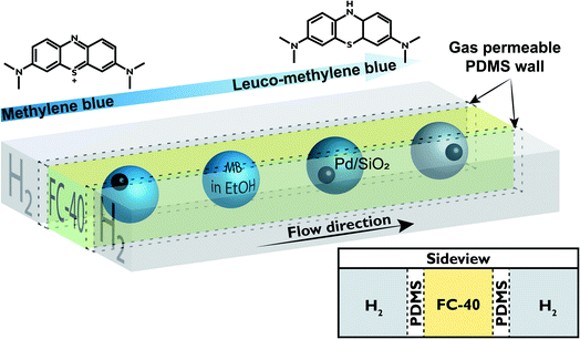
In this work, a PDMS microreactor has been developed with three parallel channels, as schematically shown in Fig. 1, to perform gas/liquid/solid catalytic reactions for the diagnostics of single catalyst particles. PDMS is a flexible polymer that is often used for the fabrication of microfluidic systems, since the fabrication of PDMS microreactors utilizes soft lithography which is relatively cheap and easy.22 Furthermore, it is known that PDMS has a high permeability to gases, such as H2 and O2, which is used to our advantage. The outer channels, as shown in Fig. 1, are used for the flow of H2 that permeates through the PDMS walls and reaches the central liquid channel. In this liquid channel droplets of methylene blue (MB) dissolved in ethanol, containing single particles of a Pd-catalyst, flow in a continuous fluorinated oil phase. As a proof of principle reaction, the hydrogenation of MB to leuco–MB that discolors from blue to colorless is performed.23 This reaction is catalyzed by 40 μm sized hollow spherical Pd/SiO2 particles encapsulated in the MB/ethanol droplets. The droplets that flow through the reactor channel, have identical residence times at any chosen position along the length of the channel. This allows in situ analysis of the ongoing reaction, by measuring the color of the droplet at various spots along the length of the channel.
Results and discussion
Microreactor design and fabrication
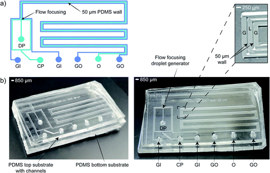
The PDMS microreactor, as shown in Fig. 2, was designed to benefit from the gas-permeability of PDMS: a thin wall of 50 μm between the gas and the droplet channel allows for fast diffusion of H2 to the liquid droplets with reactant and catalyst. The hydrogenation reaction can only take place when the three phases meet (the solid catalyst particle, the liquid MB in ethanol and the gaseous H2) and therefore starts when the catalyst particle-containing droplets enter the liquid microchannel (250 × 250 μm width and depth) surrounded by two H2 gas channels with similar cross-sectional dimensions. Ethanol droplets (containing MB) are created via a flow focusing geometry using a fluorinated hydrocarbon oil, FC-40, as the continuous phase. The droplets of ∼50 nL travel through the microreactor in 45 s with a total flow rate of 7.5 μL min−1.For the hydrogenation to take place, the gaseous H2 has to travel from the gas channels through the PDMS wall and the fluorinated oil (FC-40) continuous phase before it reaches the ethanol droplet. It is important that the 50 μm thick PDMS wall does not interfere too much with the H2 diffusion in ethanol, to prevent a change in reaction kinetics due to mass transport limitations. Fig. 3a schematically shows which factors influence the concentration of H2 in the ethanol droplet. For a flow with spherical droplets, the continuous phase is wetting the channel walls, whereas the droplet phase is non-wetting. This leads to the formation of a thin stagnant film of oil between the ethanol droplet and the PDMS wall. Fig. 3b shows that the droplets in the microreactor system are slugs rather than spherical droplets.24 Based on the small contact angle between the non-wetting slug and the wall, we assume that there is a nanometer thick (but invisible) layer of FC-40 between the droplet and the PDMS. Since FC-40 has a high H2 gas permeability (similar to PDMS),25 consequently there is no diffusion limitation caused by the FC-40 film. From this, we concluded that H2 must first diffuse into and through the PDMS wall before it can enter the ethanol droplet containing the catalyst. From Table 1, it can be observed that the diffusivity (D) of H2 through PDMS is a factor 100 higher than that of H2 through ethanol. Inside the PDMS wall and the ethanol droplet, the solubility follows Henry’s law. The solubility (S) parameter of H2 is 200 times higher in ethanol compared to PDMS.
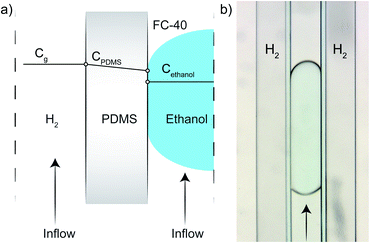 | ||
| Fig. 3 Simplified/schematic representation of the H2 concentrations in the different compartments of the microreactor (a), and a microscope image of one droplet (b). The ethanol droplets partially wet the polydimethylsiloxane (PDMS) wall and are therefore considered as ‘slugs’. Due to the high diffusivity of H2 through PDMS (1.4 × 10⁴ m2 s−1), with respect to ethanol (1.49 × 10² m2 s−1), the limiting diffusion step is for H2 to enter the ethanol droplet.27,28 | ||
The high diffusivity, but low H2 solubility in PDMS results in the fast transport of H2 through the PDMS membrane. In ethanol, the H2 diffusivity is lower, but its solubility is higher compared to PDMS, leading to H2-saturated ethanol droplets. Therefore, it is assumed that the PDMS does not introduce significant diffusion limitations. Within the droplets, chaotic advection causes fast mixing,26 leading to a homogeneous and constant H2 concentration.
Fig. 3a sketches the situation where the ethanol droplet is completely saturated with H2 and homogeneously mixed, therefore there is a discontinuity in the simplified representation at the PDMS-droplet interface. When the ethanol concentration in the droplet becomes lower because the H2 reacts with MB on the Pd catalyst, H2 can diffuse from the PDMS and dissolve into the ethanol droplet again.
Catalytic hydrogenation of methylene blue
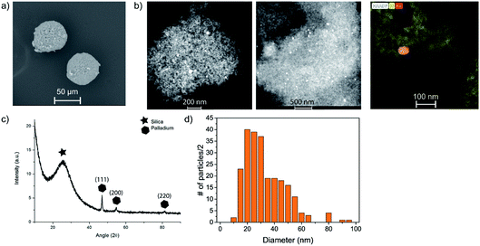
The developed PDMS microreactor was tested for the hydrogenation of MB (blue) into leuco–MB (colorless). As the catalyst, we have opted for Pd supported on hollow SiO2 spheres 40 μm in diameter. We have selected Pd as the active metal because of its known activity towards hydrogenation reactions. An added benefit is its stability in air. After a reduction step, the formed Pd particles are not prone to oxidation and can, therefore, easily be transferred through or stored in air. Our microreactor setup lacks options for in situ catalyst reduction steps, thus a stable and robust catalyst system is vital. The hollow core of the silica particles lowers their weight by a factor 10 approximately (bulk density of 0.2 mg L−1vs. skeletal density 2.5 mg L−1), to improve their flow through the microchannel. In general, catalyst particles with much higher densities than the surrounding liquid have difficulty moving inside microfluidic channels, as they tend to sink to the bottom due to gravity.30 Once stuck at the channel bottom, heavy catalyst particles cannot easily be removed because it is expected that they stick to the PDMS. Since catalyst support materials often have a higher density compared to the liquid reactants, this sinking is an important factor in microfluidic single particle diagnostics. The prepared catalyst was characterized with scanning electron microscopy (SEM), X-ray diffraction (XRD), transmission electron microscopy (TEM) and N2-physisorption. SEM and TEM images can be found in Fig. 4a and b, respectively. With SEM, the external surface and morphology was investigated. It was found that the structure and shape of the spherical SiO2 particles was intact after the preparation of the catalyst. The 40 μm porous SiO2 microparticles were too big to analyze with TEM, but after crushing them, the remaining fragments could be analyzed to determine the Pd dispersion and nanoparticle size. On average, the Pd nanoparticles are ∼25–30 nm. The particle size distribution is large, but their dispersion over the SiO2 support is homogeneous, as can be seen in Fig. 4d. In the XRD (Fig. 4c), diffraction peaks allocated to crystalline Pd were found, and with the Scherrer equation using the Full Width Half Maximum (FWHM) of the XRD peaks, an average crystallite size of ∼25 nm could be determined. The BET surface area of the particles was calculated to be ∼180 m2 g−1. To perform the hydrogenation reaction inside the droplet microreactor, a setup was built with a vertically mounted syringe pump to benefit from gravitational forces acting on the catalyst particles. A shaker was connected to the tip of the syringe, inducing vibrations in the tubing and a stir bar was added to the syringe to disperse the particles in the ethanol solution. Both measures are a precaution against particle sedimentation in the syringe or tubing. A detailed image of the setup is given in Fig. 5. The droplets were followed with optical microscopy to monitor the color change of all droplets that contained catalyst particles.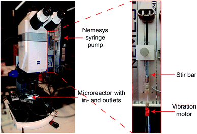 | ||
| Fig. 5 Images of the microscope setup with vertical syringe pump, syringe with stir bar and vibration motor for optimal conditions to encapsulate solid particles in droplets. | ||
As part of the experimental setup, the catalyst particles were added to the MB–ethanol syringe prior to starting the flows. Since no reaction can happen before the particles have entered the microreactor, due to the absence of H2 in the glass syringe, we have a well-defined starting time for the reaction (t0). Interestingly, after adding the Pd/SiO2 to a 20 ppm solution of MB in ethanol, a rapid color change of the fresh catalyst was observed from brown to blue, due to the adsorption of MB. Fig. 6 shows two microscopy images of the catalyst before and after adsorption of MB. This color change is advantageous for the catalyst characterization: the blue particles should return to their original brown color upon hydrogenation. This color change effect is expected to be more pronounced compared to a discoloration of the light blue color of the MB droplet itself and therefore easier to detect. As a proof of concept experiment, droplets containing blue Pd/SiO2 particles were followed over time, without any liquid flow, leading to stagnant droplets. It can be seen in Fig. 7 that after starting the H2 flow the red/green/blue (RGB) values, representing the color of the particle, reach a plateau over time. During the experiments a H2 sensor (Industrial Scientific Pro Gas Badge) is put next to the microreactor for safety reasons. The minimum amount it can detect is 1 ppm and during all experiments, this level is never reached.
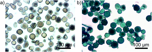 | ||
| Fig. 6 Two optical images of Pd/SiO2 before (a) and after (b) adding them to 20 ppm methylene blue (MB) in ethanol. The blue color is caused by adsorption of MB on the surface of the solid particles. | ||
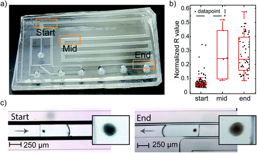
These results show the working principle of the PDMS hydrogenation microreactor: H2 can diffuse through the PDMS wall and dissolves in the reactant droplet. However, for single particle diagnostics, these experiments should be performed in flow. Therefore, the same hydrogenation of MB was performed at a total flow of 7.5 μL min−1, leading to a droplet formation rate of 1 droplet per s and a residence time of 45 s in the microchannel. The analysis of particles in flow is more difficult compared to the static experiment. Therefore, three monitoring regions for characterization were defined at the start, middle and the end of the microchannel (Fig. 8a). In this way, all particles can be analyzed for three different reaction times. Fig. 8c shows two sets of images of Pd/SiO2 in a MB–ethanol droplet recorded at the start and end regions.
Indeed, the blue color of the particles at the start of the channel has disappeared towards the end of the channel. From these results, we conclude that H2 also permeates the PDMS wall, dissolves in the ethanol droplet and participates in the reaction when the droplets experience a flow. Thus, our microreactor design is working: within the 45 s residence time (tr) in the microchannel, the MB hydrogenates to the colorless leuco–MB. To support these findings, control experiments without H2 or the active catalyst are performed: the particles stay blue during their residence in the microchannel. These results are shown in Fig. S1.† The color change is most visible for the more concentrated MB, adsorbed on the particles. Empty droplets contain the same initial concentration of MB as droplets containing a particle. However, the concentration in the droplets is too low to be visible in the images and both empty droplets and particle containing droplets appear ‘white’ and have no discernable color change in the RGB level. With the presented setup, the encapsulation of particles in droplets was relatively straightforward. However, fluctuating concentrations of particles near the inlet of the microreactor often led to multiple particles per droplet, as can be seen in Movies M1–M4.†
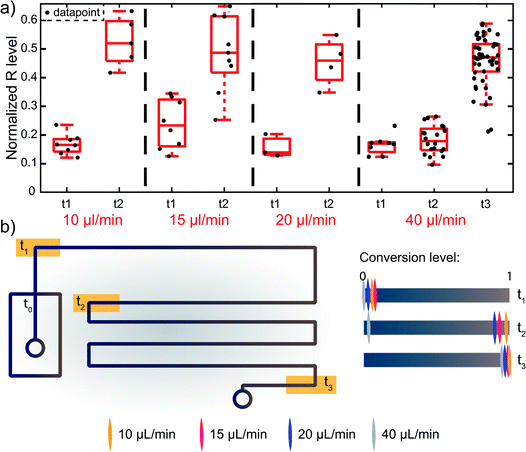
For the flow experiments, a statistically relevant analysis was performed by monitoring the RGB levels of the acquired movies in Matlab. The movies were screened for the presence of catalyst particles in a droplet using a small window at three positions on the microreactor (start, middle, and end) as indicated in Fig. 8a. Fig. S2† shows three examples of particles found at these different locations. Matlab processing was used to find the frames containing particles. The RGB values of all particles were collected using a line profile positioned perpendicular to the flow direction. From these line profiles, it can be clearly seen that the particles have lower RGB values than the background. The lowest 10 RGB values of each particle are summed and averaged to obtain the RGB value for a particle at each position. This tracking allowed for an evaluation of the RGB levels for each particle. Fig. 8b shows a boxplot of red levels for multiple particles at the start, middle and at the end of the flow channel. The datapoints obtained from the Matlab script are plotted on top of the boxplot. Only the red value is shown, as that is the value with the most distinctive change upon discoloration, as shown in Fig. 7. The values are normalized with respect to a reference position on the PDMS, denoted as background. From this plot, the color change of Pd/SiO2 catalyst particles flowing through the microchannel is clearly visible. At the start, the blue particles show low red values, whereas the brown particles at the middle and end show high red values. For the middle region, only a few particles (i.e., 6) could be measured, leading to less sound statistics. However, due to the similar red color value in the box plot at the middle compared to the end position, it is concluded that the hydrogenation has already been completed at the middle position (54 mm after droplet formation and exposure to H2).
Interestingly, this hydrogenation is a fast reaction and does not need the full residence time of 45 s (when using a total flow of 7.5 μL min−1) in the microreactor to be completed. Due to the gradual color change from blue to brown, it is difficult to pinpoint the exact position in the microreactor where the hydrogenation is completed, but it is approximated that the reaction is completed within 10 s, because the red value of the particle does not change after this point, as shown in Fig. 7, from frame F onwards. Movies M1 to M4† show hydrogenations at different total flow speeds and indicate the position where the hydrogenation is complete. For a total flow of 7.5 μL min−1, ∼1 droplet per second passes the analysis region. For high-throughput experimentation it holds that it is better to use a higher flowrate. Increasing the flowrate to 40 μL min−1 leads to larger, but less stable droplets (Movie M4†), but the hydrogenation still takes place and the droplet size does not seem to affect the reaction kinetics. Fig. 9 shows the red color values for the start and middle of the reaction channel, for four different flow rates. It can be seen that up to a total flow of 20 μL min−1 (10/10, w/o), the reaction has completed by the mid-region of the microreactor. For a total flow of 40 μL min−1 (20/20, w/o), the residence time of a droplet in the microreactor is decreased to 8.5 s. At this flow rate, the full channel length is needed for completion of the reaction, meaning that the reaction time for the hydrogenation of MB, at these conditions, is ±8 s. Therefore, the end position is also measured at this flow rate.
Conclusions
In this work, we show the proof of concept of a PDMS microreactor for high-throughput, multiphase catalytic reactions, demonstrating the liquid-phase hydrogenation of MB. A liquid channel with Pd/SiO2 particles of 40 μm encapsulated in droplets containing 20 ppm MB in ethanol are flanked by two gas channels with H2, separated with 50 μm PDMS walls. Due to the high permeability of PDMS, H2 diffuses into the liquid channels and facilitates the Pd-catalyzed hydrogenation of MB at room temperature. In approximately 8 s the reaction completes, as concluded from the discoloration of the particles in droplets going from blue (due to adsorbed MB) to brown (their original color). Droplets containing single particles could be analyzed individually to allow for the diagnostics of multiple heterogeneous catalyst particles, as opposed to the use of packed-bed or wall-coated reactors. This newly developed microreactor has, therefore, proven to be useful for the single particle diagnostics of catalyst particles in complex multiphase reactions. With this we have a new diagnostics tool in hand to improve the statistical relevance of single catalyst particle analysis and bridge the gap towards bulk characterization. In addition, a safe and relatively easy method has been demonstrated to work with H2, as no H2 leak was detected by a commercial sensor during any of the experiments, and only small amounts of gas are involved. Furthermore, by placing the PDMS chip on a heating stage, reactions at elevated temperatures can be performed. The thermal stability of crosslinked PDMS allows for heating up to 400 °C before it starts to degrade,31 but in this situation more problems arise, such as the boiling of solvents or a non-uniform heating of the microreactor. In addition, the optical properties of PDMS allow reactions to be monitored with visible (laser) light, therefore allowing users to perform in situ UV-vis or Raman spectroscopy. These techniques should be optimized in a way that they can work fast and can detect individual droplets at high flow rates. Finally, more sophisticated microreactor designs with microfluidic droplet sorters can be implemented to sort the catalyst particles of interest.Experimental
Microreactor fabrication
Microreactors were fabricated in PDMS with standard soft- and photolithography methods, as described elsewhere.32 The SU-8 mold was made in the cleanroom of the MESA+ Nanolab at the University of Twente. SU-8 photoresist was spin-coated on a silicon substrate (P-type <100>, single side polished, 500 μm) and patterned with a photomask by exposure to UV-light. Structures with a height and width of 250 μm for both the gas channels and the liquid channel were created. The spacing between the gas and liquid channel is 50 μm. This mold was used to fabricate the inverse replica in PDMS. A liquid mixture of the base- and curing agent (10![[thin space (1/6-em)]](https://www.rsc.org/images/entities/char_2009.gif) :
:![[thin space (1/6-em)]](https://www.rsc.org/images/entities/char_2009.gif) 1, Sylgard 184, Dow Corning) was degassed and poured over the molds. After thermally curing the PDMS at 60 °C for 3 h, the layer was peeled from the master. Inlet and outlet holes of 1 mm diameter are punched into the PDMS after which it was treated in an O2 plasma oven for 2 min and subsequently bonded to another flat layer of PDMS acting as a bottom substrate, followed by heating the assembled microreactor to 60 °C for 30 min. Bonding of the structured PDMS slab to the flat bottom slab had to be carried out carefully, to prevent distortion and collapse of the relatively flexible thin PDMS walls. A chip yield of approximately 75% has been achieved. In total, 20 chips have been fabricated and tested.
1, Sylgard 184, Dow Corning) was degassed and poured over the molds. After thermally curing the PDMS at 60 °C for 3 h, the layer was peeled from the master. Inlet and outlet holes of 1 mm diameter are punched into the PDMS after which it was treated in an O2 plasma oven for 2 min and subsequently bonded to another flat layer of PDMS acting as a bottom substrate, followed by heating the assembled microreactor to 60 °C for 30 min. Bonding of the structured PDMS slab to the flat bottom slab had to be carried out carefully, to prevent distortion and collapse of the relatively flexible thin PDMS walls. A chip yield of approximately 75% has been achieved. In total, 20 chips have been fabricated and tested.
Catalyst preparation and characterization
Pd was deposited on hollow spherical 40 μm SiO2 particles (Materium450) via incipient wetness impregnation of a 6 mM solution of PdCl2 in ethanol. After an equilibrium period of 8 h, the ethanol was slowly evaporated by heating the mixture at 60 °C. After carefully drying the particles, the sample was calcined and reduced in a flow of air and H2 consecutively. The prepared catalyst was characterized with powder XRD, SEM and N2-physisorption. The crystalline phase of the Pd/SiO2 catalyst was measured using a Bruker-AXS D2 Phaser equipped with a Co Kα radiation source (λ = 1.78897 Å) with 2θ from 10–90° (increments of 0.1 and scan steps of 1 s). SEM images were collected in back-scattered electron mode using a Phenom table top machine. For TEM, a diluted sample of the crushed Pd/SiO2 in ethanol was drop-casted on lacey copper carbon grids (van Loenen Instruments, 300 mesh grid). The samples were analyzed with a ThermoFisher Scientific Talos F200X equipped with an X-FEG electron source operated at 200 kV. Energy-dispersive X-ray spectroscopy (EDX) images were made using the same apparatus with a Super-X™ EDX detector in STEM mode. A Micromeritics TriStar 300 V6.08 A was used for N2-physisorption measurements at 77 K. The BET equation was used to obtain the specific surface areas. The catalyst particles were added to a syringe with 20 ppm MB in ethanol at a low concentration: 1 mg in 1 mL. This low concentration was needed to increase the possibility of having one particle per droplet, as the amount of particles per droplet follows the Poisson distribution.33 The blue MB quickly adsorbs on the surface of the silica spheres, leaving blue particles in a pale blue liquid. After entering the microchannel, the droplets with blue Pd/SiO2 particles flow in between the two gas channels of the H2 supply.Microfluidic reaction: chemicals and materials
The microreactor was designed with three parallel channels, a center-channel for the liquids and two surrounding channels for the gas (all channels have a depth and width of 250 μm). H2 was flushed through the gas channels at 0.75 mL min−1 total flow (using a Bronkhorst mass flow controller of 0–1 mL min−1). In the liquid channel 20 ppm MB in ethanol droplets (with the added catalyst) in a continuous phase of the fluorinated FC-40 oil were created. FEP polymer tubing from Idex-HS (ID = 500 μm, OD = 1/16′′) in combination with Hamilton syringes (1000 μL) and a Nemesys (Cetoni) syringe pump were used to create droplets. Flow rates were varied between 2.5 to 20 μL min−1 and 5 to 20 μL min−1 for the ethanol (dispersed phase) and fluorinated oil (continuous phase), respectively. Microscopy images were made and data acquisition was done with a Zeiss Axio Zoom.V16 microscope using bottom illumination, equipped with a PlanNeoFluar Z 1× zoom objective and an Axiocam 105 color camera.Matlab data analysis
All movies acquired were screened for the presence of catalyst particles in a droplet, using a small window at three positions of the microreactor (start, middle, and end). Fig. S2† shows three examples of particles found at these locations. To find the center of the particles, all red values in the window are added column-wise and then multiplied by −1. The result is the bottom row of images in Fig. S2.† Here it can be seen that the position of the particle results in a peak, because the red values are significantly lower for the particle than for the background. The presence of a droplet interface also results in a peak, but by looking at the width of the peak as well, they can be filtered from actual particles. The findpeaks function in Matlab is used to find the position of the particle peak. With this position a line (yellow line in Fig. S2†) can be drawn over the middle of the particle, plotting the RGB values along this line, as seen in the top row of images in Fig. S2.†Conflicts of interest
There are no conflicts to declare.Acknowledgements
We thank Johan Bomer (University of Twente) for his contributions to this research, Nynke Krans (Utrecht University) for TEM measurements and Fang Liu (Utrecht University) for help and related discussions. This work was supported by the Netherlands Centre for Multiscale Catalytic Energy Conversion (MCEC), an NWO Gravitation program funded by the Ministry of Education, Culture and Science of the government of the Netherlands.References
- B. Sun, X. Meng, S. Wang, S. Sun and F. Xiao, Acta Phys.-Chim. Sin., 2006, 22, 441–444 CrossRef CAS.
- H. Fang, Q. Xiao, F. Wu, P. E. Floreancig and S. G. Weber, J. Org. Chem., 2010, 75, 5619–5626 CrossRef CAS PubMed.
- T. Zech, G. Bohner and J. Klein, Catal. Today, 2005, 110, 58–67 CrossRef CAS.
- F. G. Welsch, K. Stöwe and W. F. Maier, ACS Comb. Sci., 2011, 13, 518–529 CrossRef CAS PubMed.
- G. M. Whitesides, Nature, 2006, 442, 368–373 CrossRef CAS.
- S. Haeberle and R. Zengerle, Lab Chip, 2007, 7, 1081–1220 RSC.
- E. Y. Basova and F. Foret, Analyst, 2015, 140, 22–38 RSC.
- X. Casadevall, Chem. Commun., 2011, 47, 1936–1942 RSC.
- H.-D. Xi, H. Zheng, W. Guo, A. M. Ganan-Calvo, Y. Ai, C.-W. Tsao, J. Zhou, W. Li, Y. Huang, N.-T. Nguyen and S. H. Tan, Lab Chip, 2017, 17, 751–771 RSC.
- R. M. Schoeman, E. W. M. Kemma, F. Wolbers and A. van den Berg, Electrophoresis, 2014, 35, 385–392 CrossRef CAS PubMed.
- H. A. Bunzel, X. Garrabou and M. Pott, Curr. Opin. Struct. Biol., 2018, 48, 149–156 CrossRef CAS PubMed.
- A. Autour and M. Ryckelynck, Micromachines, 2017, 8, 128 CrossRef.
- D. Cai, A. Neyer, R. Kuckuk and H. M. Heise, J. Mol. Struct., 2010, 976, 274–281 CrossRef CAS.
- R. Burger, L. Amato and A. Boisen, Biosens. Bioelectron., 2016, 76, 54–67 CrossRef CAS.
- H. P. L. Gemoets, Y. Su, M. Shang, V. Hessel, R. Luque and T. Noël, Chem. Soc. Rev., 2016, 45, 83–117 RSC.
- G. Takei, T. Kitamori and H. Kim, Catal. Commun., 2005, 6, 357–360 CrossRef CAS.
- M. Liu, X. Zhu, R. Chen, Q. Liao, H. Feng and L. Li, Chem. Eng. J., 2016, 301, 35–41 CrossRef CAS.
- J. Kobayashi, Y. Mori, K. Okamoto, R. Akiyama, M. Ueno, T. Kitamori and S. Kobayashi, Science, 2004, 304, 1305–1309 CrossRef CAS PubMed.
- P. Garstecki, I. Gitlin, W. Diluzio, G. M. Whitesides, E. Kumacheva and H. A. Stone, Appl. Phys. Lett., 2004, 85, 2649–2651 CrossRef CAS.
- J. Tan, S. W. Li, K. Wang and G. S. Luo, Chem. Eng. J., 2009, 146, 428–433 CrossRef CAS.
- A. Günther, S. A. Khan, M. Thalmann, F. Trachsel and K. F. Jensen, Lab Chip, 2004, 4, 278–286 RSC.
- J. C. Mcdonald, D. C. Duffy, J. R. Anderson, D. T. Chiu, H. Wu, O. J. A. Schueller and G. M. Whitesides, Electrophoresis, 2000, 21, 27–40 CrossRef CAS PubMed.
- Y.-N. Liu, X. Zhou, X. Wang, K. Liang, Z.-K. Yang, C.-C. Shen, M. Imran, S. Sahar and A.-W. Xu, RSC Adv., 2017, 7, 30080–30085 RSC.
- H. Song, D. L. Chen and R. F. Ismagilov, Angew. Chem., Int. Ed., 2006, 45, 7336–7356 CrossRef CAS PubMed.
- S. K. O. Ntwampe, C. C. Williams and M. S. Sheldon, Afr. J. Biotechnol., 2010, 9, 1106–1114 CrossRef CAS.
- H. Song, M. R. Bringer, J. D. Tice, C. J. Gerdts and R. F. Ismagilov, Appl. Phys. Lett., 2003, 83, 4664–4666 CrossRef CAS PubMed.
- T. C. Merkel, V. I. Bondar, K. Nagai, B. D. Freeman and I. Pinnau, J. Polym. Sci., Part B: Polym. Phys., 2000, 38, 415–434 CrossRef CAS.
- K. Sporka, J. Hanika, V. Ruzicka and M. Halousek, Collect. Czech. Chem. Commun., 1971, 36, 2130–2136 CrossRef CAS.
- M. S. Wainwrlght, T. Ahn, D. L. Trimm and N. W. Cant, J. Chem. Eng. Data, 1987, 32, 22–24 CrossRef.
- D. Huh, J. H. Bahng, Y. Ling, H. H. Wei, O. D. Kripfgans, J. B. Fowlkes, J. B. Grotberg and S. Takayama, Anal. Chem., 2007, 79, 1369–1376 CrossRef CAS PubMed.
- J. González-Rivera, R. Iglio, G. Barillaro, C. Duce and M. R. Tinè, Polymers, 2018, 10, 616 CrossRef PubMed.
- D. B. Weibel, W. R. Diluzio and G. M. Whitesides, Nat. Rev. Microbiol., 2007, 5, 209–218 CrossRef CAS PubMed.
- D. J. Collins, A. Neild, A. DeMello, A. Liu and Y. Ai, Lab Chip, 2015, 15, 3439–3459 RSC.
Footnotes |
| † Electronic supplementary information (ESI) available. See DOI: 10.1039/d0fd00006j |
| ‡ Both authors contributed equally. |
| This journal is © The Royal Society of Chemistry 2021 |

