
Design and properties of multiple-emitter luminescent metal–organic frameworks
Shanghua
Xing
ab and
Christoph
Janiak
 *ab
*ab
aHoffmann Institute of Advanced Materials, Shenzhen Polytechnic, 7098 Liuxian Blvd, Nanshan, Shenzhen, China
bInstitut für Anorganische Chemie und Strukturchemie, Heinrich-Heine-Universität Düsseldorf, Universitätsstraße 1, Düsseldorf 40225, Germany. E-mail: janiak@uni-duesseldorf.de
First published on 3rd September 2020
Abstract
Multi-emitter luminescent metal–organic frameworks (LMOFs) possess multiple emission bands that can cover a wider spectral region, which is a prerequisite for white-light emitting and multi-dimensional ratiometric fluorescent sensing. By taking advantage of the structure features of MOFs (e.g. hybrid structure, porosity) and the various luminescence origins of LMOFs, different emission sources can be designed and combined with each other into a homogeneous solid-state LMOF phase with the desired emission properties. This feature article reviews the recent development of multi-emitter LMOFs, and focuses on the design strategies for creating multi-emitter LMOFs based on at least two emission centers. The design strategies are classified into and discussed along six categories: type I metal-linker emitters, Type II multi-metal emitters, Type III multi-linker emitters, Type IV chromophore@LMOF (chromophore incorporated into an already luminescent MOF), Type V chromophores@MOF (multi-chromophores embedded into a non-emissive MOF) and Type VI multi-heterostructure LMOF emitters. The new class of Type VI includes core–shell structured LMOF⊃LMOF and nanostructured LMOF/LMOF thin films on a substrate. The good spatial separation between the different emitters in their own but chemically linked LMOF phase can retain their emission properties with less interference with the other emitters.
 Shanghua Xing | Shanghua Xing received her PhD at the State key Laboratory of Inorganic Synthesis and Preparative Chemistry at Jilin University, China in 2017 under the guidance of Prof. Ruren Xu and Assist. Prof. Guanghua Li, working on single or multi-emitter luminescent MOFs. Since 2017, she spent two years as a PD researcher at Nagoya University in the group of Prof. Masataka Nagaoka, working on the theoretical study of flexible MOFs. In 2019, she joined the group of Prof. Christoph Janiak. Her research focusses on the experimental and theoretical study of MOFs with luminescence and gas adsorption properties. |
 Christoph Janiak | Christoph Janiak is a full professor at the University of Düsseldorf since 2010, with research interests in porous materials (e.g. MOFs), mixed-matrix membranes, metal nanoparticles, ionic liquids and catalysis. Until 2018 he was a visiting professor at Wuhan University of Technology and currently, he is a guest professor at the Hoffmann Institute of Advanced Materials at Shenzhen Polytechnic in China. He has (co-)authored about 530 research papers and is a Fellow of the Royal Society of Chemistry (FRSC). |
1. Introduction
Metal–organic frameworks (MOFs) represent the most promising multifunctional material development in recent years.1 MOFs as functional luminescent materials benefit from a well-ordered porous structure, versatile emissive building blocks and tunable photophysical properties. Luminescent MOFs (LMOFs) have been the focus of several reviews.2–5 Recent interest with respect to luminescence and MOFs is derived from the versatile possibilities for creating multi-emitter LMOFs with a wide promising potential in light-emitting diodes (LEDs),6 optical sensors,3,7,8 bioimaging9,10 or anticounterfeiting applications.11 Making full use of multiple emission source assembly, the emission band of multi-emitter LMOFs can be finely modulated over the whole visible light region, which is crucial to achieve the tunable emission that contributes to white-light emission.6,12 Furthermore, the relative intensity changes for the different emissions in multi-emitter LMOFs can act as a luminescent signal for specific analytes.13–15 This provides multidimensional recognition, reproducibility, self-calibration and visible sensing. To date, multi-emitter materials have been developed in several chemical systems such as small chromophore molecules,16 polymers,17 and nanoparticles.18 Thus, the use of multi-emitter LMOFs, as recently new emerging materials, offers the following advantages over, so-far, other chemical systems.(1) Versatile emissive sources from a wide selection of different emissive metals or linker building blocks of the MOF, or by the embedding of chromophore guests into the intrinsic pores of MOFs are available to be combined with each other to create multi-emitter LMOFs as a homogeneous single luminescent phase.2,19,20 Even if there is an interparticle or interlayer phase boundary in a so-called multi-heterostructured emitter (see below) one could still view this as a single LMOF phase since the different phases are constructed on the lattice match between MOFs with similar topologies.21,22
(2) They benefit from the modifiable pore surface of MOFs, such that the chromophore moieties can be integrated into the MOF matrix by post-synthetic modification (PSM).23–27 This provides possibilities for creating multi-emitter LMOFs, in which the multiple emission is added through the PSM-chromophore to a pristine single-emitter LMOF or even a non-luminescent MOF.
(3) The emissive organic and inorganic chromophores within LMOFs can retain their individual luminescence properties, or can optimize multi-emission efficiency from collaborative emitting processes.28–31
(4) The porosity of MOFs over non-porous luminescent materials32,33 allows different kinds of chromophore guests to be embedded into the MOF pores to produce the multi-emitter LMOF composite with possible also synergistic effects.34,35 In addition, the encapsulated chromophore guest can be rigidified within the MOF (matrix) channel to reduce non-radiative processes.
(5) Isostructural LMOFs can be built from similar metal centers or organic linkers, which allows the fabrication of the hetero-metal or hetero-linker LMOFs with the possibility to create multi-emitter LMOFs by integrating more than one LMOF phase into a single framework.36,37
The various preceding reviews have discussed the luminescence properties of single-emitter LMOFs and their versatile applications.4,11,38 This feature article reviews the recent progress for the development of multi-emitter LMOFs which have advanced rapidly in recent years. The design methods by which different multiple emission sources can be combined for creating multiple-emitter LMOFs are critically summarized in this communication. A recent review by Yin and Yin also summarized the development of MOFs with multiple luminescence emission,39 thereby highlighting the timely nature of this field. In our review, besides giving different examples, we also include multi-chromophore guest emitters embedded in non-luminescent MOFs and multi-heterostructure LMOF emitters of the SURMOF type.
2. Design strategies for multi-emitter LMOFs
The design strategies of multi-emitter LMOFs can be classified into six major categories (Scheme 1) for which we partially (for Type I, II and IV) followed the designation introduced by Yin and Yin in their recent review.39 Type I is metal-linker emitters, mainly from the lanthanide ions (Ln3+) with the emissive metal. Type II is multi-metal emitters either from f–f heterometallic or from s,p/d–f heterometallic centers. Either a lanthanide Ln3+ center is mixed as a co-emitter into a homometallic lanthanide-LMOF or into a homometallic main group- or transition metal-LMOF. Type III refers to multi-linker emitters. Different-chromophore linkers assemble into a single MOF phase. The luminescence origin of multi-chromophore linker LMOFs can come from the individual linkers but can also be modulated from an inter-linker charge transfer or excited-state intramolecular proton transfer (ESIPT). Type IV denotes a chromophore incorporated into an already luminescent MOF, that is chromophore@LMOF. Type V is a multi-chromophore embedded into a non-emissive MOF, that is chromophores@MOF. Type VI corresponds to multi-heterostructure LMOF emitters including core–shell structured LMOF⊃LMOF and nanostructured LMOF/LMOF thin films on the substrate. In the following sections, the detailed information for each design will be described with representative examples. In the above Type I and III-assignments the linker is indeed meant as a bridging ligand. We note that there can also be terminal ligands in multi-emitter MOFs, which may be regarded as another Type. As the focus in this feature is on MOFs with their characteristic metal, linker and guest building blocks, we have refrained from including terminal ligands as emissive sources. Cases where a non-emissive linker is post-synthetically turned luminescent through the addition of a luminescent group by covalent attachment are regarded as Type IV or V, that is, the post-synthetic modification is considered like the addition of a guest.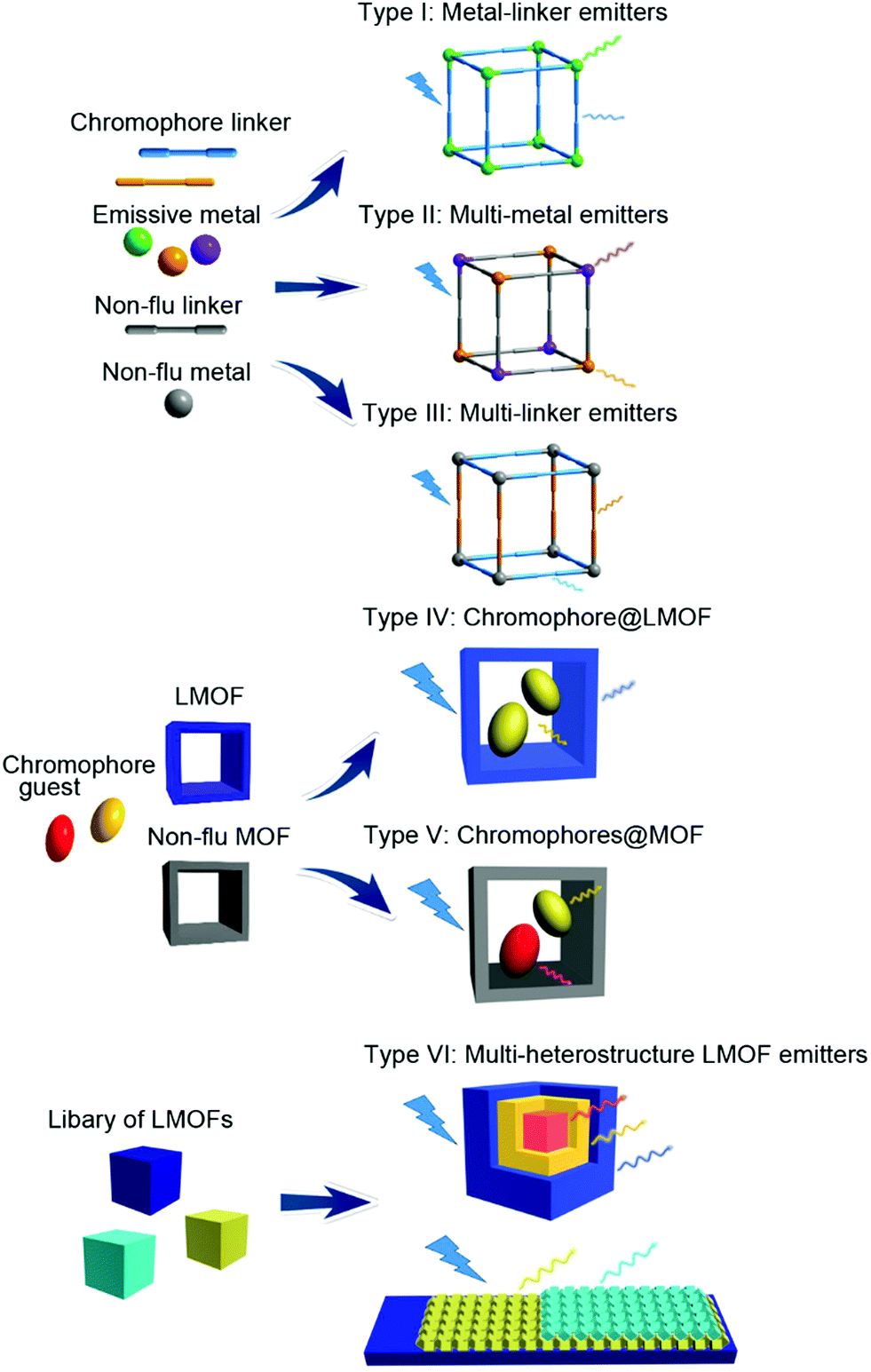 | ||
| Scheme 1 Multi-emitter luminescent MOFs (LMOFs) differentiated in a simplified scheme according to the origin of the emission. The scheme also implies that the luminescent metals and linkers can only be doped into a non-luminescent framework. There could also be more than two different luminescent metal, linker or framework types. In the “luminescent framework” building block (LMOF) in Types IV and VI the luminescence can come from either metal or ligand or both. | ||
3. Type I: metal-linker emitters
The 4f electrons of a lanthanide ion (Ln3+) participate chiefly in two types of transitions: (i) the non-strictly Laporte-forbidden f–f transitions, which are hence often weak but typically sharp and narrow, and (ii) the allowed f–d transitions, which are broad and intense.19,40 The long excitation lifetimes of (i) due to the formally prohibited transition and large Stokes shift allow for various opportunities for the engineering of specialized luminescent materials. The f–f transition bands can become intense by coupling the Ln3+ species to a ligand that can participate in the ligand-to-metal energy transfer process, which is known as the antenna effect (Scheme 2). Such antenna ligands typically contain extended aromatic π-systems. Energy transfer efficiency depends on the excited triplet state of the ligand and the excited state of the Ln3+.41 An inefficient antenna effect, that is with only partial energy transfer to Ln3+, induces the co-existence of the characteristic emission of the organic ligand and Ln3+. Such metal–ligand/linker emitters can then be regarded and utilized as one type of multi-emitter LMOF and have been widely reported.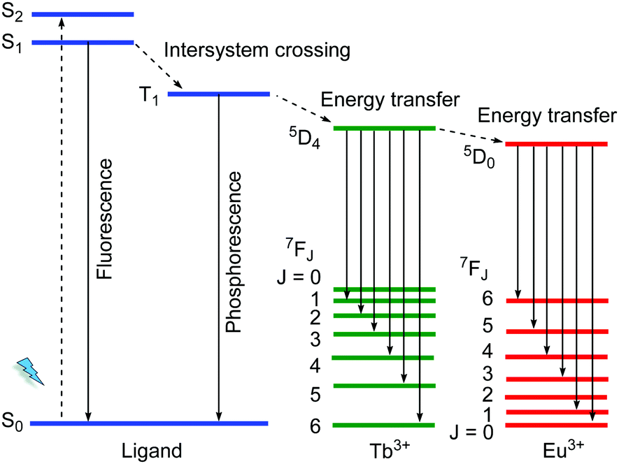 | ||
| Scheme 2 Schematic diagram for an antenna effect (energy transfer) from ligands to Ln3+ as well as the energy transfer process from Tb3+ to Eu3+. | ||
For example, in the MOF [(CH3)2NH2]3[Eu3(fdc)4(NO3)4] (fdc = 9-fluorenone-2,7-dicarboxylate) the energy difference between the lowest triplet excited state T1 of the linker (17![[thin space (1/6-em)]](https://www.rsc.org/images/entities/char_2009.gif) 794 cm−1) and of 5D0 Eu3+ (17241 cm−1) is less than 1500 cm−1.42 This increased the probability of back-energy transfer from Eu3+ to the linker. Under the excitation of 365 nm, the dual-emission derived from the linker and Eu3+ could be monitored. At the low temperature, the back-energy transfer was prohibited and thus the Eu3+ emission dominated. As the temperature increased, the linker emission is essentially constant while the Eu3+ emission is gradually decreased due to the thermal activation of nonradiative decay. The MOF was suggested as a ratiometric luminescent thermometer under physiological temperature (up to 320 K).
794 cm−1) and of 5D0 Eu3+ (17241 cm−1) is less than 1500 cm−1.42 This increased the probability of back-energy transfer from Eu3+ to the linker. Under the excitation of 365 nm, the dual-emission derived from the linker and Eu3+ could be monitored. At the low temperature, the back-energy transfer was prohibited and thus the Eu3+ emission dominated. As the temperature increased, the linker emission is essentially constant while the Eu3+ emission is gradually decreased due to the thermal activation of nonradiative decay. The MOF was suggested as a ratiometric luminescent thermometer under physiological temperature (up to 320 K).
Another example, a Zn2+/Dy3+-MOF [H(H2O)8][DyZn4(imdc)4(im)4] was prepared based on H3imdc and imidazole (Him) linkers (H3imdc = 4,5-imidazole dicarboxylic acid).43 The Zn2+ metal center is preferably coordinated by the soft nitrogen imidazolate linkers in a {ZnN3O2} coordination environment, while the Dy3+ ion has a carboxylate-only {DyO8} coordination (Fig. 1a). There is no water coordination with Dy3+, and thus non-radiative quenching by energy transfer from Dy3+ to the high energy O–H oscillators was prohibited, and the energy transfer efficiency from the linker to Dy3+ is maximally efficient. Under the excitation at 250 to 290 nm (Fig. 1b), Dy–Zn-MOF only exhibits the typical emissions of Dy3+. While under excitation at 300 to 400 nm the relative emission intensity shifted from Dy3+ to the linker-based emission (431 nm). The cool white light emission was achieved by this dichromatic emitter with yellow emission of Dy3+ and blue emission of im− and imdc3− when excited at 340 nm.
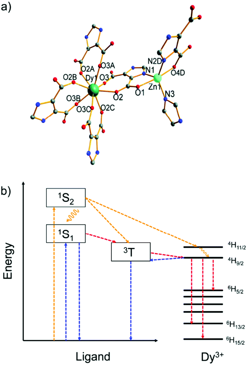 | ||
| Fig. 1 (a) Coordination environments of Zn2+ and Dy3+ in the MOF [H(H2O)8] [DyZn4(imdc)4(im)4]. (b) Energy level diagram of the yellow and white light emission from the Zn2+/Dy3+-MOF. Color scheme: yellow, pathways for excitation at 290 nm; blue, pathways for excitation at 340 nm; red, pathways for excitation at both 290 and 340 nm. Reproduced from ref. 43 with permission from the Royal Society of Chemistry, copyright 2016. | ||
4. Type II: multi-metal emitters
4.1. f–f heterometallic centers
Ln3+ is the standard emissive metal type in multi-metal luminescent MOFs, also mostly by taking advantage of the antenna effect from organic linkers or ligands (Scheme 2).44–46 The most straightforward and often optimal strategy for the preparation of multi-emitter f–f heterometallic LMOFs is the introduction of one Ln3+ as a co-emitter through doping into a homometallic lanthanide-LMOF. The dominant Ln3+ is in situ substituted during the framework synthesis with one with similar ionic radii and chemical properties at the same position (crystallographic site-sharing). Binary Ln3+/Ln3+-doped LMOFs are a basic type of multi-emitter LMOF. A popular pair is Eu3+/Tb3+ with an extended visible-light emission region and efficient spectral-tuning by changing the Ln3+ component ratio in the solid solution.3,39,47,48For example, green, yellow and red emission colors were conditioned by the use of different ratios of Eu3+ and Tb3+ in a series of [EuxTb4−x(bpt)4(DMF)2(H2O)8] networks (x = 0.31, 1, 2 and 3) with biphenyl-3,4′,5-tricarboxylate (bpt3−) as a linker.49 The efficient antenna effect from an antenna linker to Ln3+ induced the absence of linker-based emission. Eu0.31Tb3.69-MOF displayed remarkable temperature-dependent emission behavior over 50–300 K, in which the emission intensity of Tb3+ decreased and that of Eu3+ increased as the temperature increased. This was attributed to the energy transfer from Tb3+ to Eu3+, where the corresponding 5D0 (Eu3+) lifetime was longer than that of the homometallic Eu-MOF and the 5D4 (Tb3+) lifetime was shorter than that of the analogous Tb-MOF at the same temperature.49
A Eu3+/Tb3+ dual-emitter was also doped into homometallic La3+ or Gd3+-MOFs to create multi-emitter LMOFs,48,50 in which the multiple emission comes from the doped binary Eu3+/Tb3+-emitters together with linker-based emission.51 The homometallic La3+ or Gd3+-MOFs generally show only the ligand-based emission due to the optically inert nature of La3+ as well as the impossible energy transfer from the ligand to Gd3+ (the lowest excited energy of Gd3+ is higher than the triplet excited energy of ligand).52 The Eu3+/Tb3+-emitters are separated by La3+ or Gd3+ in the crystal lattice, which have the dual-function to avoid aggregation-induced quenching of the Eu3+/Tb3+-emitters and prevent the ligand-based emission to be fully suppressed by the otherwise strong Eu3+/Tb3+ emission.6,53
4.2. s,p/d–f heterometallic centers
Unlike f–f transitions of Ln3+ with sharp and narrow bands, d–d transitions of transition (d-block) metal ions or s–p transition of main group (s,p-block) metal ions generally show broad emission bands with half widths of over a hundred nanometers.54 For d–d transitions, the emission is usually quite weak and only observable at low temperature. On the other hand, d-block metal ions without unpaired electrons and coordinated to a chromophore ligand can participate in metal-to-ligand or ligand-to-metal charge transfer (MLCT or LMCT) for the emission properties of LMOFs.55–57 MLCT is the partial electron transfer from a metal-localized orbital to a linker-localized orbital.54 The d-block metal ions with d6- (low-spin), d8- or d10-electronic configurations (e.g. d6-Ru2+, d10-Au+) prefer the MLCT process. LMCT is the partial electron transfer from the linker-localized orbital to the metal-localized orbital. An LMCT process occurs in d0- or d10-transition metal ions (e.g. Zn2+, Cd2+) and in s2-main group metal ion LMOFs.Regardless of whether an MLCT or LMCT process operates, it can be utilized as an emission source in multi-emitter LMOFs.2 The incorporation of Ln3+ as a co-emitter into a homometallic d- or s,p-block LMOF gives s,p/d–f heterometallic LMOFs and provides the possibility to create multi-emitter LMOFs. The typical MOF linkers like di- or tricarboxylates, are not preferably selected to fabricate d–f heterometallic LMOFs due to the unselective coordination of d- and f-block metals. Whereas a mixed-functional linker like azolate/carboxylates provides good possibilities for tailored mixed-metal MOF synthesis based on matching acidity and basicity within the HSAB concept.58
A Tb3+/Cu+-MOF, [Tb2(Cu8I8)(pba)6(H2O)4] with the 3-(pyridin-4-yl)benzoate (pba−) linker is an example of a d–f heterometallic MOF design based on a mixed-functional linker by in situ synthesis.59 The Cu+ metal center of Cu8I8 is preferably coordinated by the soft nitrogen of pba−, while the Tb3+ ion has a carboxylate to form the 1D chain (Fig. 2a). Under excitation at 380 nm, Tb3+/Cu+-MOF shows dual-emission including the characteristic emission of Tb3+, which is assigned to the antenna effect from pba− to Tb3+, as well as the emission of copper(I) halide clusters, which is attributed to the triplet cluster-centered excited state (halide-metal charge-transfer and d–s transition). Upon the exposure to different solvents (benzene, toluene, p-xylene, and mesitylene), the relative emission intensity between Tb3+ and Cu8I8 is varied with visual signal change (Fig. 2b). And also, the Tb3+/Cu+-MOF can differentiate isomers (ether, butyl alcohol, 2-butyl alcohol, and tert-butanol) and homologues of butyl alcohol (methanol, ethanol, and n-propanol). The structure change of the copper(I) halide cluster is sensitive to the energy of a cluster-centered excited state, which is thus attributed to different emission behaviors towards different analytes.59
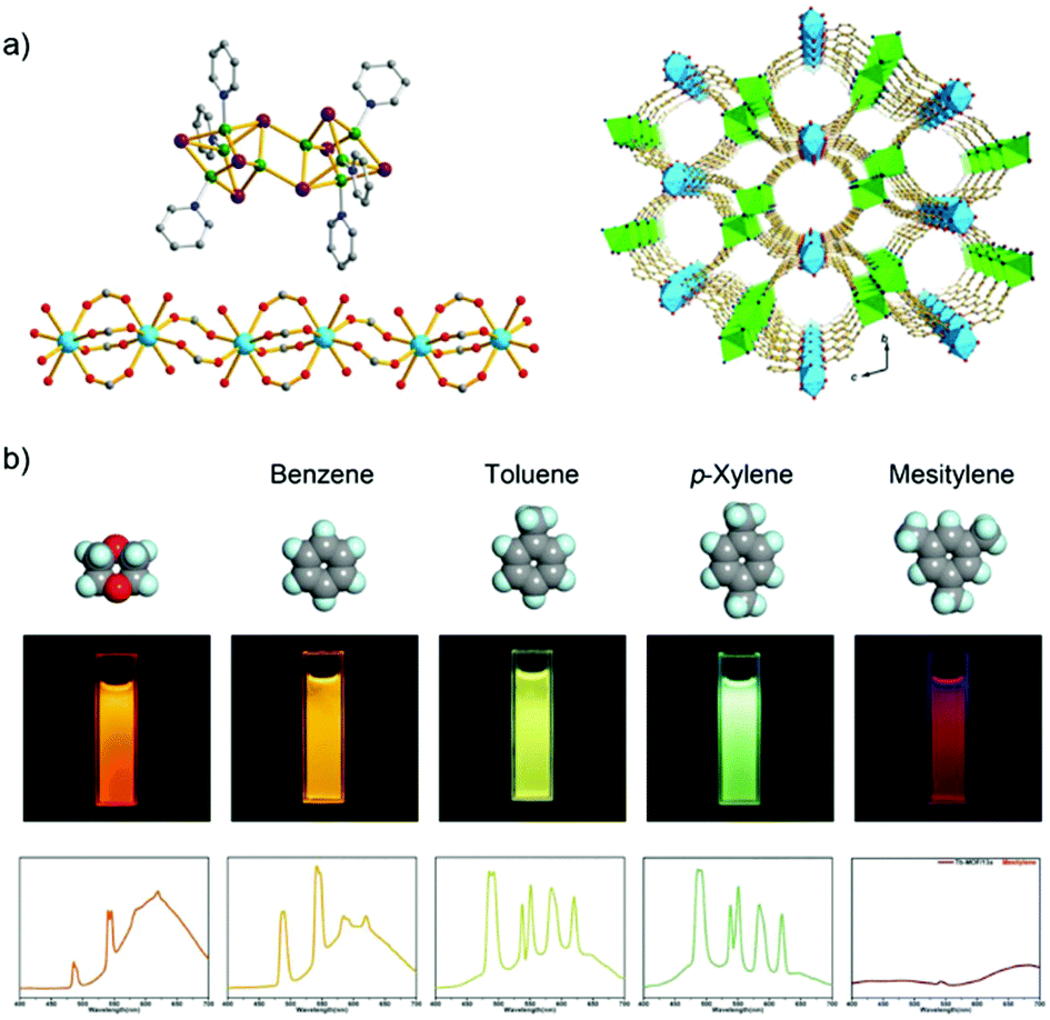 | ||
| Fig. 2 (a) Structure of the Cu8I8 cluster (left top), the 1D lanthanide carboxylate chain (left down), and 3D structure of the Tb3+/Cu+-MOF (right). (b) Luminescence spectra and photographs of Tb3+/Cu+-MOF upon exposure to different analyte solvents including benzene, toluene, p-xylene, and mesitylene. Reproduced from ref. 59 with permission from the American Chemical Society, copyright 2016. | ||
5. Type III: multi-linker emitters
One possibility of incorporation of organic chromophores into a MOF structure is by using them as the linkers. The chromophore-linker assembly with a metal center in a network can improve the rigidity of the molecular linker conformation with less degrees of freedom for molecular vibrations. This rigidification can minimize non-radiative relaxation and in turn enhance emission efficiency (e.g. quantum yield, life time, emission intensity).6 In addition, the spatial arrangement of chromophore linkers within the well-ordered MOF structure can give rise to various interesting emitting processes,2 such as MLCT, LMCT or ligand-to-ligand charge transfer (LLCT). Thus, the integration of more than one chromophore linker with a suitable metal center (that cannot quench the ligand-based emission) into a single MOF phase can fabricate multi-emitter LMOFs.14,38For example, the two chromophore linkers 1,3,5-tris(4-carboxyphenyl)-benzene (btb3−) and 5-amino-1-H-tetrazolate (atz−) were used to prepare the LMOF [(CH3)2NH2][Zn(btb)2/3(atz)] with an anionic framework.60 Two atz− linkers coordinate to a single tetrahedral Zn2+ center which brings not only the two atz− chromophores but also the atz− and btb3− chromophores into close proximity to enable electronic interactions between these linker chromophores (Fig. 3a). This allows a tunable emission and multiple charge transfer to be produced between the chromophores. At cryogenic temperature, under 330 nm excitation the emission band at 377 nm was assigned to the intra-ligand charge transfer (ILCT) of the btb3− linker with π–π* transition. Several emission bands at 477, 510 and 544 nm were ascribed to LLCT between the adjacent atz− linkers. As the temperature increased, the emission of btb3− was increased slightly, while the emission of atz− decreased gradually (Fig. 3b). This was attributed to the thermal equilibrium between two separated excited states of dual-emission coupled with Dexter energy transfer between the atz− and btb3− chromophores. The intensity ratio of I377/510 had a linear correlation with the temperature from 30 to 130 K, which offers potential for a cryogenic temperature sensor.
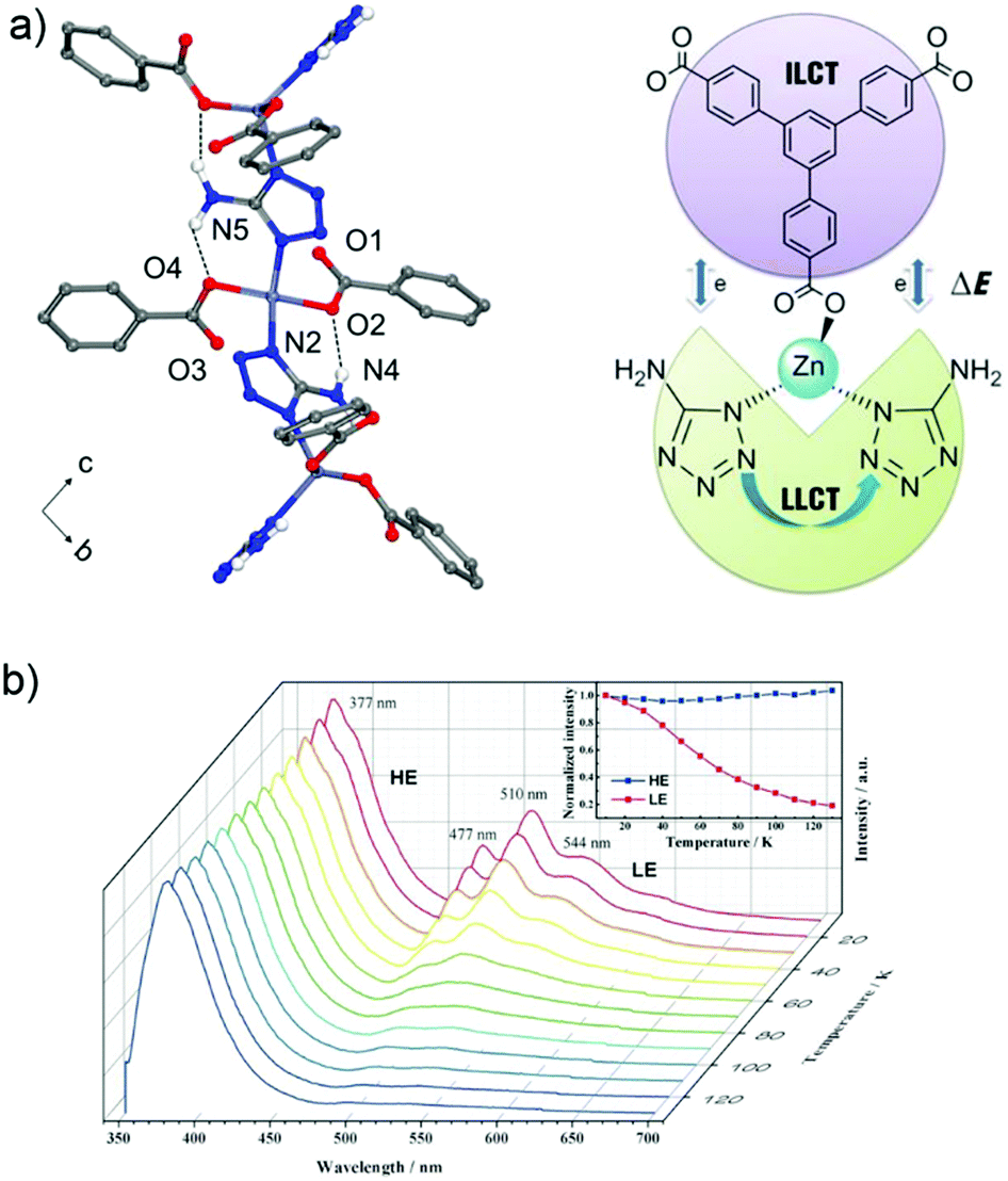 | ||
| Fig. 3 (a) 1D zigzag chain in [(CH3)2NH2][Zn(btb)2/3(atz)] with N–H⋯O hydrogen bonds (top). The Dexter energy transfer (DET) mechanism in a dual emissive system (down). (b) Emission spectra of [(CH3)2NH2][Zn(btb)2/3(atz)] recorded between 10 and 130 K (λex = 330 nm). Reproduced from ref. 60 with permission of John Wiley & Sons, Ltd, copyright 2016. | ||
The concept of organic-substitutional solid solutions was applied to incorporate multiple chromophore dicarboxylate linkers (with identical linker length) with red (R), green (G) and blue (B) emissions into the UiO-type MOF [Zr6O4(OH)4(NonFlu)6] by substituting its non-fluorescent linker (NonFlu) (Fig. 4a).61 The emission profiles with 10%-R or G or B linker were significantly different compared to the neat solid linker, and resembled the emission feature of the liquid-phase linker solution. The incorporation of two or three chromophore linkers in the MOF exhibited the combined emission of each chromophore linker (Fig. 4b). The emission color could be finely regulated by the initial amounts of the RGB linkers. The three-chromophore linker system with an appropriate ratio of RGB exhibited white light emission with a quantum yield of 4.3%.
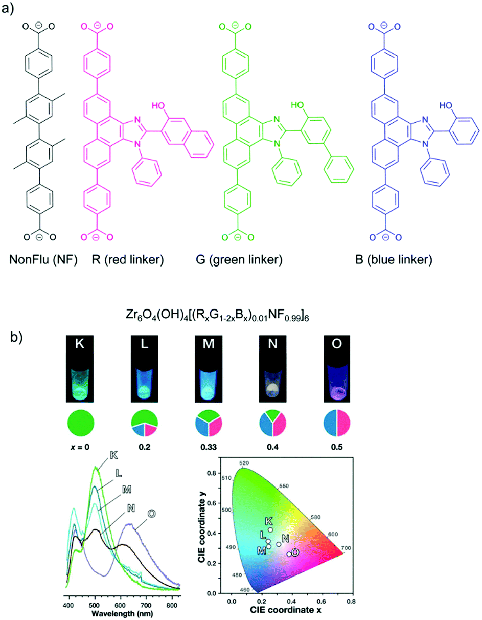 | ||
| Fig. 4 (a) Solid solution formation with different RGB chromophore linkers in the UiO-type MOF [Zr6O4(OH)4(NonFlu)6]. (b) Luminescence images (top), spectra (bottom left) and CIE chromaticity coordinates (bottom right) (under λex = 365 nm irradiation) of the one to three-component RGB MOFs (with chromophore composition indicated in the cake diagrams below the luminescence images). Reproduced from ref. 61 with permission from the American Chemical Society, copyright 2019. | ||
Another example for energy transfer among distinct chromophore linkers is the multi-linker MOF MUF-77, [Zn4O(hxtt)4/3(gua)1/2(atpt)1/2] (tpt2− = terephthalate, bpdc2− = 4,4′-biphenlydicarboxylate, hxtt3− = alkyl-functionalized truxene-2,7,12-tricarboxylate, x = different R, alkyl group), which endows highly tunable emission spectra (Fig. 5).30 A series of derivatives of isostructural MUF-77 was prepared in which the hxtt linker carried different alkyl groups (Fig. 5a) for emission modulation (hmtt with R = Me; hbtt with R = Bu; hhtt with R = Hex and hott with R = Oct). The gua2− and atpt2− linkers emit an intense yellow (∼565 nm) and blue emission (∼430 nm), respectively. The adsorption of the gua2− linker (acceptor) also has a large spectral overlap with the emission spectra of the atpt2− and hxtt3− linkers. The alkyl substituents on hxtt change the energy transfer from gua2− to the two other chromophore linkers and the concomittant contributions of blue and yellow emission to produce a cool to warm white light emission (Fig. 5b).
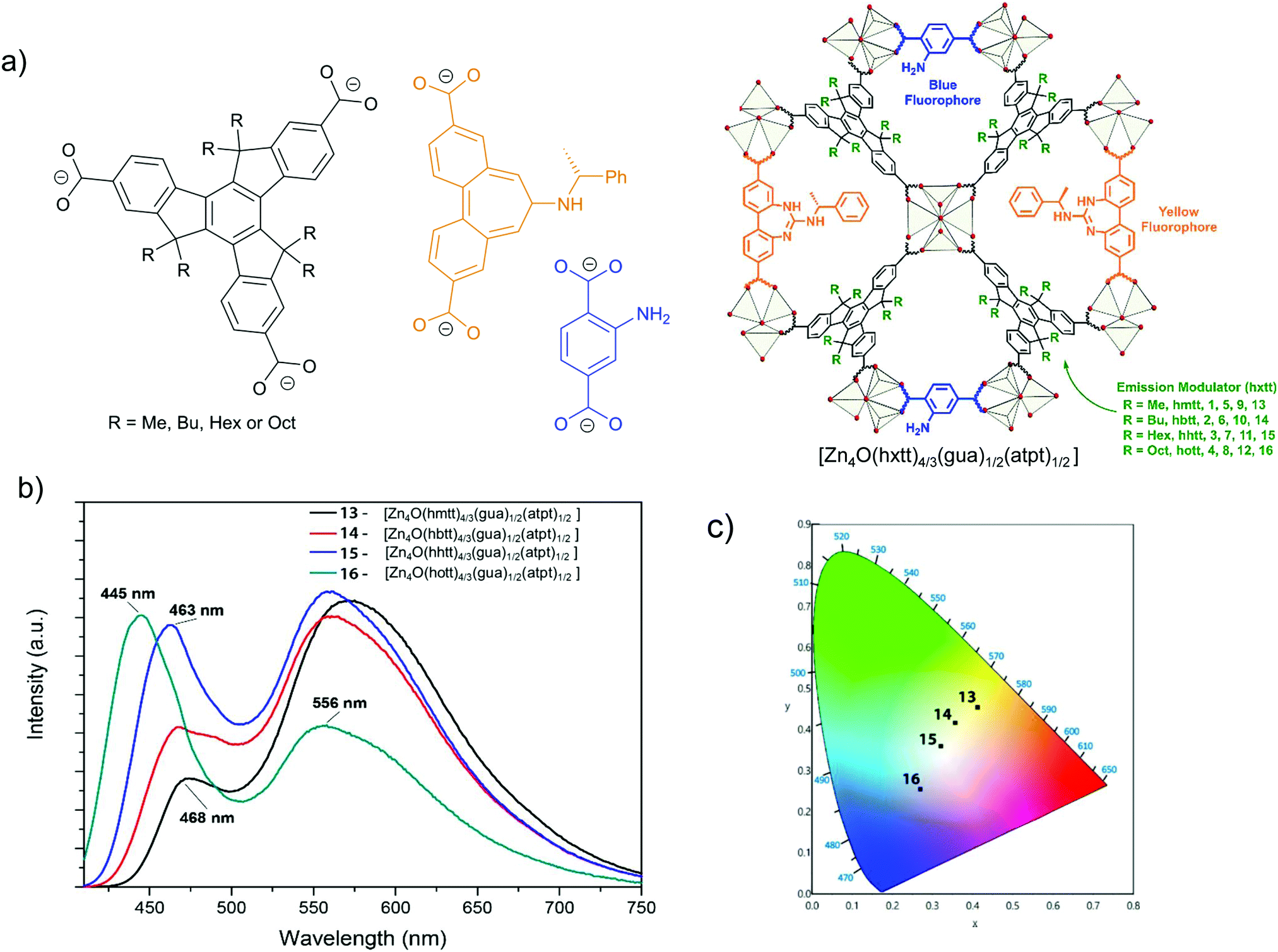 | ||
| Fig. 5 (a) The three distinct linkers hxtt3−, gua2− and atpt2− of MUF-77, s. In hxtt3− “x” refers to the different alkyl groups of R = Me (hmtt), Bu (hbtt), Hex (hhtt) and Oct (hott). (b) Schematic structure of MUF-77. (c) Emission spectra of four [Zn4O(hxtt)4/3(bgua)1/2(atpt)1/2] analogs, with different hxtt linkers. The photograph shows an UV LED after coating with [Zn4O(hhtt)4/3(bgua)1/2(atpt)1/2] which acts as a phosphor to generate white light (inset). Reproduced from ref. 30 with permission from the American Chemical Society, copyright 2018. | ||
The MOF [Zn6(hpi)4(hpi2c)4] is an example for chromophore linkers with excited-state intramolecular proton transfer (ESIPT), namely, 2-(4,5-diphenyl-1H-imidazolate-2-yl)phenol (hpi−) and 5-[2-(2-hydroxyphenyl)-4,5-diphenyl-1H-imidazol-1-yl]isophthalate (hpi2c2−). In an ESIPT process (Scheme 3)62 the electron transfer from the ground E to the excited state E*, is accompanied by a proton transfer to an excited state K* from which the radiative decay then returns back to the original state E in the sequence E → E* → K* → K → E.63 Most ESIPT-chromophores possess dual-emission from the E* and the K* state.
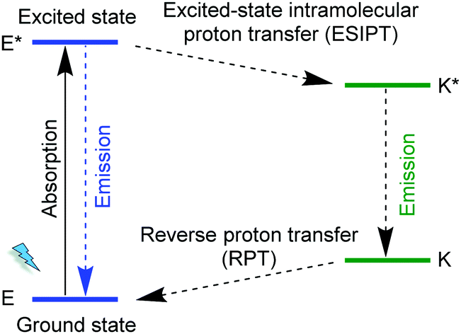 | ||
| Scheme 3 Schematic representation of an excited-state intramolecular proton transfer, ESIPT process. | ||
An example of an ESIPT process is depicted with the linker hpi2c2− in Fig. 6. An intramolecular hydrogen bond is formed in the hpi2c2− linkers between the 2-phenol-OH group and the imidazole-N atom.64 Under 338 nm excitation, the Zn-MOF [Zn6(hpi)4(hpi2c)4] shows two-emission bands at 408 and 555 nm with an additional shoulder band at 460 nm. The enol emission of hpi2c2− appears at 408 nm. The shoulder emission band at 460 nm was ascribed to the keto emission of hpi2c2−. Thus, both enol- and keto-emission can be observed due to the presence of an ESIPT process within hpi2c2−. The 555 nm emission band was assigned to an aggregation-related excimer state, as this band was absent in the dilute hpi2cH2 linker solution.
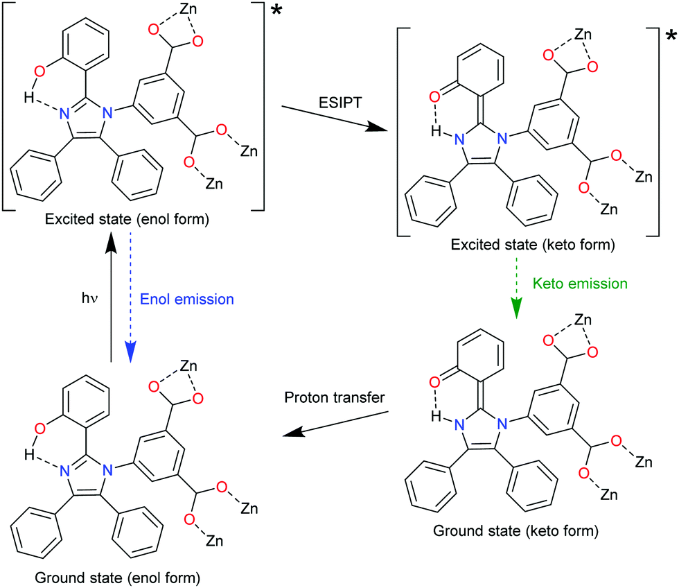 | ||
| Fig. 6 The ESIPT process of hpi2c2− linkers in [Zn6(hpi)4(hpi2c)4]. Reproduced from ref. 64 with permission of John Wiley & Sons, Ltd, copyright 2016. | ||
The incorporation of ESIPT chromophores into MOF structures could straightforwardly act as a single dual-emission center or pseudo-multi-linker MOF emitter.65–67 Also, two different ESIPT chromophores can be integrated into a MOF structure as multiple emitters. However, such ESIPT chromophores in MOFs are rarely reported, so far.
6. Type IV: chromophore-incorporated into luminescent MOF emitters, chromophore@LMOF
The inherent porous nature of MOFs enables the encapsulation of versatile chromophore guests into the MOF pores.40,68,69 The MOF host can incorporate a chromophore guest with reduced molecular vibrations to minimize the non-radiative relaxation and, thereby enhance the guest emission efficiency. In addition, a distribution of isolated chromophore guests as a solid solution within MOFs can prevent aggregation-induced emission quenching. Thus, the use of MOFs as hosts makes it possible to create multiple emission with the fluorescence or phosphorescence of the embedded chromophores, alone or in combination with the luminescence from the MOF. If the multi-emitter luminescence derives from the chromophore guest and from the MOF then we assign the material to Type IV as chromophore@LMOF. If the multiple emission is from the chromophore guests only and the MOF remains non-luminescent then we have a Type V material with chromophores@MOF (see below). The chromophore guests can be Ln3+ species, organic dyes, metal-complex luminophores and quantum dots (QDs). As “chromophore guests” we consider here species which are not part of the original MOF. They can be incorporated post-synthetically or in situ during the synthesis into the MOF.Through the post-synthetic incorporation, the chromophore guests can be attached to the framework by non-covalent (supramolecular) interaction or could also become covalently or coordinatively bound to the framework, mostly at the linker. In the latter case the “guest” becomes essentially part of the framework and may, for example, thereby transform a previously non-luminescent linker into a luminescent one. Still, we consider such a case as Type IV or V because of the post-synthetic chromophore “incorporation”.
6.1. Ln3+-guest@LMOF
Ln3+ ions or Ln3+ complexes can be integrated into the MOF linker by post-synthetic modification (PSM) to achieve multiple emission using a preformed s,p/d-block LMOF with a linker which still possesses donor atom sites (e.g. –COO−, –SO3− or 2,2′-bipyridine moiety).70 The multiple emission properties then come from different Ln3+ emitters combined with the emission from the LMOF itself. An example was realized in MOF-253 [Al(OH)(bpydc)] with the linker 2,2′-bipyridine-5,5′-dicarboxylate (bpydc2−). The still available 2,2′-bipyridine donor sites within MOF-253 were used to chelate Ln3+-β-diketonate complexes by post-functionalization.23 The appropriate ratio of Sm3+/Tb3+, as well as the β-diketonate molecule, was grafted into the nanosized MOF-253. The product with 10% Sm, 90% Tb@MOF253_acac (molar fraction of 10% Sm3+ and 90% Tb3+, acac = acetylacetone) shows wavelength- and temperature-dependent emission properties under a simple UV lamp. By changing the excitation wavelength from 302 to 365 nm, the emission color was turned from yellow, which was assigned to the combination of the characteristic emission of Tb3+ and Sm3+, to green, which was the emission produced from MOF-253 itself. As the temperature increased from 270 to 350 K, the Sm3+ emission was increased gradually at the cost of Tb3+ emission (λex = 302 nm). Under 365 nm excitation, only the emission intensity of MOF-253 itself was changed.A simple way to introduce one more emission center is the encapsulation of Ln3+ into the anionic framework of an already emitting LMOF by ion-exchange with the charge-balancing cations.69,71 The dimethylammonium cation ([Me2NH2]+, DMA+), which is generally a charge-balancing ion for anionic frameworks, is widely used to post-exchange with Ln3+.69 MOFs can serve as a rigid matrix to protect Ln3+ from solvent emission quenching. For example, DMA+ within the anionic channels of bio-MOF-1 [DMA]2[Zn8(ad)4(bpdc)6O] (ad− = adeninate; bpdc2− = biphenyldicarboxylate) was post-exchanged with different Ln3+ ions (Tb3+, Sm3+, Eu3+ and Yb3+)69 and served as protection for the Ln3+ emission from water-induced quenching.69 At the same time, bio-MOF-1 sensitized the Tb3+ and Sm3+ emission. For Tb3+ or Sm3+@bio-MOF-1, then dual-emission was monitored from the characteristic emission of Tb3+ or Sm3+ with the emission from bio-MOF-1 as the second emitter (Fig. 7).
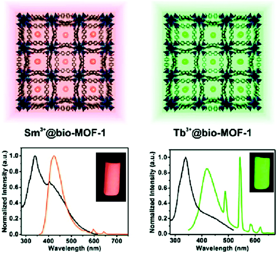 | ||
| Fig. 7 The encapsulation scheme and luminescence spectra of Sm3+ (left) and Tb3+ (right) into bio-MOF-1. Reproduced from ref. 69 with permission from the American Chemical Society, copyright 2011. | ||
6.2. Dye-guest@LMOF
Organic dyes with a planar aromatic structure often emit in the dilute liquid solution state but their emission in the neat solid state is weakened or even totally quenched due to intermolecular interactions, such as π–π stacking. The structure of MOFs can serve as a host matrix for solid solutions of organic dyes to be efficiently separated so that they exert liquid solution-like emission properties.32,72,73 An encapsulated organic dye in an already luminescent MOF is a way to achieve multiple emission from this dye@LMOF composite.74–76For example, the Cd-LMOF [Cd(ipt)(bim)] (ipt2− = isophthalate, bim = benzimidazole) emits blue fluorescence at 401 nm with UV irradiation, λex = 365 nm. After turning off the UV irradiation, Cd-LMOF still emits green phosphorescence at 520 nm with ∼10 s visible emission duration, which was derived from the T1 to S0 radiative transition of the ipt2− linker. Through the encapsulation of an organic dye into Cd-LMOF, a dual-emission band of Cd-LMOF (∼401 nm) and the dye was monitored in the fluorescence spectra. The dye included 4-methylumbelliferone (BMU), fluorescent green B (FGB), rhodamine 123 (Rh123), ∼6G (Rh6G) or ∼B (RhB). The phosphorescence color can be tuned from green to red by encapsulating different dyes into the Cd-LMOF. The adsorption of encapsulated dyes had a large spectral overlap with the phosphorescence of the Cd-LMOF, thus allowing phosphorescence energy transfer from Cd-LMOF to dye molecules. For example, the quantum yield of RhB@Cd-LMOF was 12.35%, which was two-fold higher than for the Cd-LMOF itself. Additionally, the phosphorescence lifetime of Cd-LMOF monitored at 520 nm decreased from 765 to 293 ms after RhB encapsulation. The multi-color phosphorescence of different dye-encapsulated Cd-LMOFs could be utilized in anticounterfeiting stamps.74,75
Trapping the cationic dye form of RhB in the channels of the anionic framework in [Me2NH2][Tb3(dcpcpt)3(HCOO)]·DMF·15H2O (H3dcpcpt = 3-(3,5-dicarboxylphenyl)-5-(4-carboxylphenyl)) via an ion exchange yielded stable co-luminescence of RhB and Tb3+ ions from 300–390 nm, as an excitation-wavelength-independent yellow light emission. This RhB@Tb-LMOF was shown to allow sensitive and selective detection of nitrofuran antibiotics via luminescence quenching and of quinolone antibiotics via luminescent color-change.76
The introduction of metal–ligand emitters can also be realized by integrating the chromophores through post-synthetic modification (PSM) with a MOF linker, such that the multi-emission then comes from the PSM-chromophore linker and from the characteristic emission of Ln3+. In the MOF [Eu(atpt)1.5(phen)(H2O)] (atpt2− = 2-aminoterephthalate, phen = 10-phenanthroline) the –NH2 group of the atpt2− linker was used for post-synthetic integration of methyl red (MR) by covalent amide binding through the –COOH group of MR.24 MR@Eu-MOF then showed a pH-dependent emission behavior, where the MR emission was enhanced and red-shifted along with the decreased Eu-based emission from pH = 4 to 10 (Fig. 8b and c). This can be ascribed to an efficient reversed energy transfer from the Eu-MOF to MR, and was further proven by the increased MR lifetime in MR@Eu-MOF. The pH-dependent emission of MR@Eu-MOF allowed the detection of histamine (HI). For a practical application, portable sensory hydrogels of MR@Eu-MOF were prepared to detect HI vapor. Upon the exposure of the hydrogels to HI vapor and as the pH was increased (due to the HI basicity), MR emission was increased and Eu emission decreased (Fig. 8c), along with the hydrogel color change from red to blue. Additionally, HI concentration and dual MR- and Eu-emission can act as input and output signals in a logic gate (Fig. 8d and e).
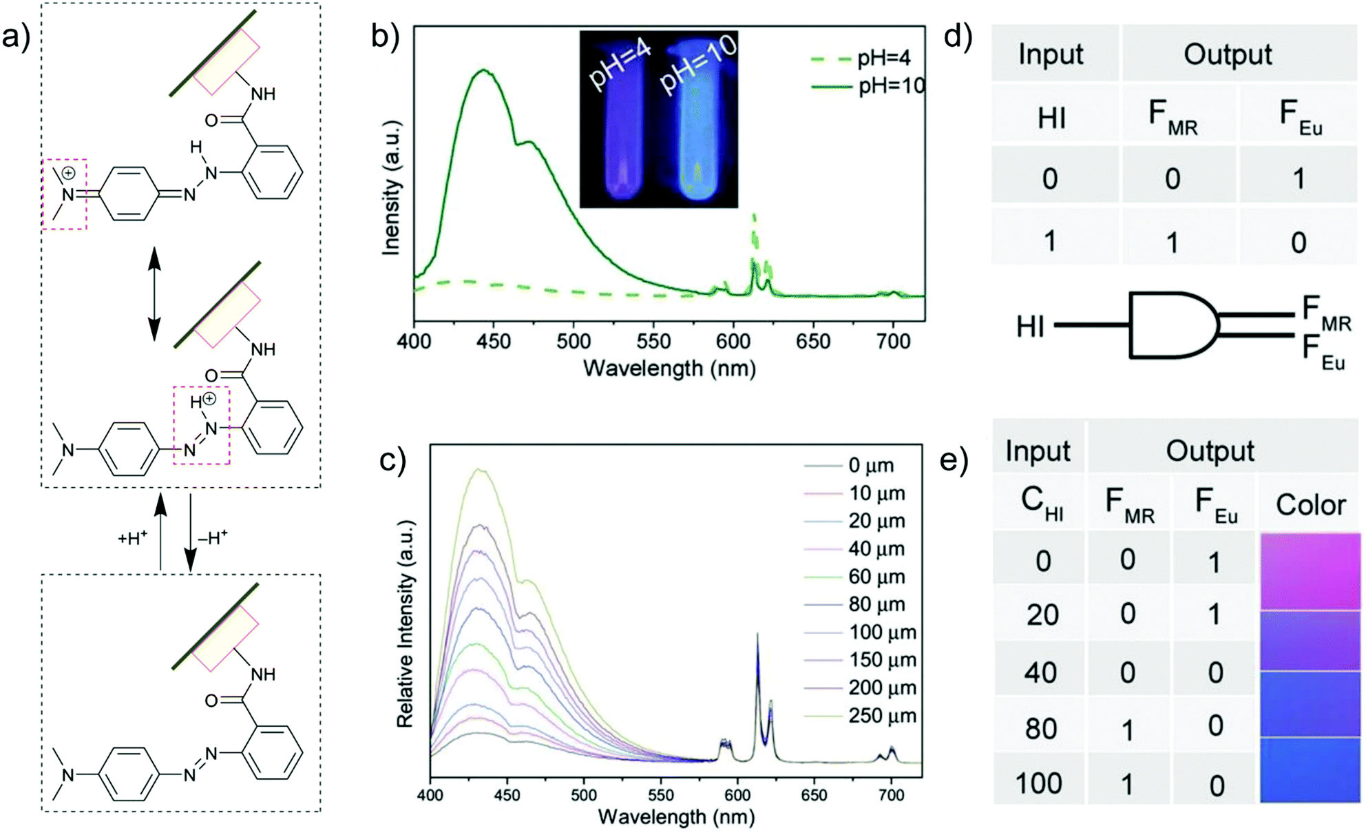 | ||
| Fig. 8 (a) Acid/base equilibrium of MR@Eu-MOFs. (b) Emission spectra of MR@Eu-MOFs in different pH solutions. (c) Histamine (HI) concentration-dependent emission spectra of MR@Eu-MOFs. (d and e) One-to-two decoder logic gate of MR@Eu-MOFs corresponding to the color change towards HI sensing. The presence and absence of HI was defined as “1” or “0”, respectively for the input signal. The normalized fluorescence signals of MR (FMR, MR emission) and Eu3+ (FEu, Eu emission) were taken as the dual output with a threshold value of 0.5. In the absence or at low concentration of HI, FMR does not increase and FEu does not decrease significantly, generating the output (0,1). After exposure to HI (higher concentration), FMR turns on and FEu turns off, generating the output (1,0). At an intermediate HI concentration, both FMR and FEu are below the threshold value and give the output (0,0). Reproduced from ref. 24 with permission of John Wiley & Sons, Ltd, copyright 2017. | ||
6.3. Metal-complex guest@LMOF
Transition metal-complexes can possess luminescence properties with high quantum yield.77 Cationic complexes are alternative promising candidates as emission centers to encapsulate into an anionic framework of suitable MOFs through ion exchange.For example, the blue-emitting Zn-MOF [DMA]2[Zn2(L)(H2O)] (L6− = 2,5-(6-(3-carboxyphenylamino)-1,3,5-triazine-2,4-diyl-diimino)diterephthalate) yielded white-light emission with the appropriate molar amount of red-emitting [Ir(CF3-ppy-F2)2(bpy)]+ and green-emitting [Ru(bpy)3]2+ encapsulated (Fig. 9a–c).78 The tunable red-green-blue emission acted as a multidimensional ratiometric sensor towards different volatile organic solvents, due to the solvent influence on the energy transfer efficiency from the LMOF to the metal complexes. For nitroaromatic sensing, time-dependent evolution of the two ratios (IMOF/IIr and IMOF/IRu) was added as the third dimension to differentiate the analytes (Fig. 9d).
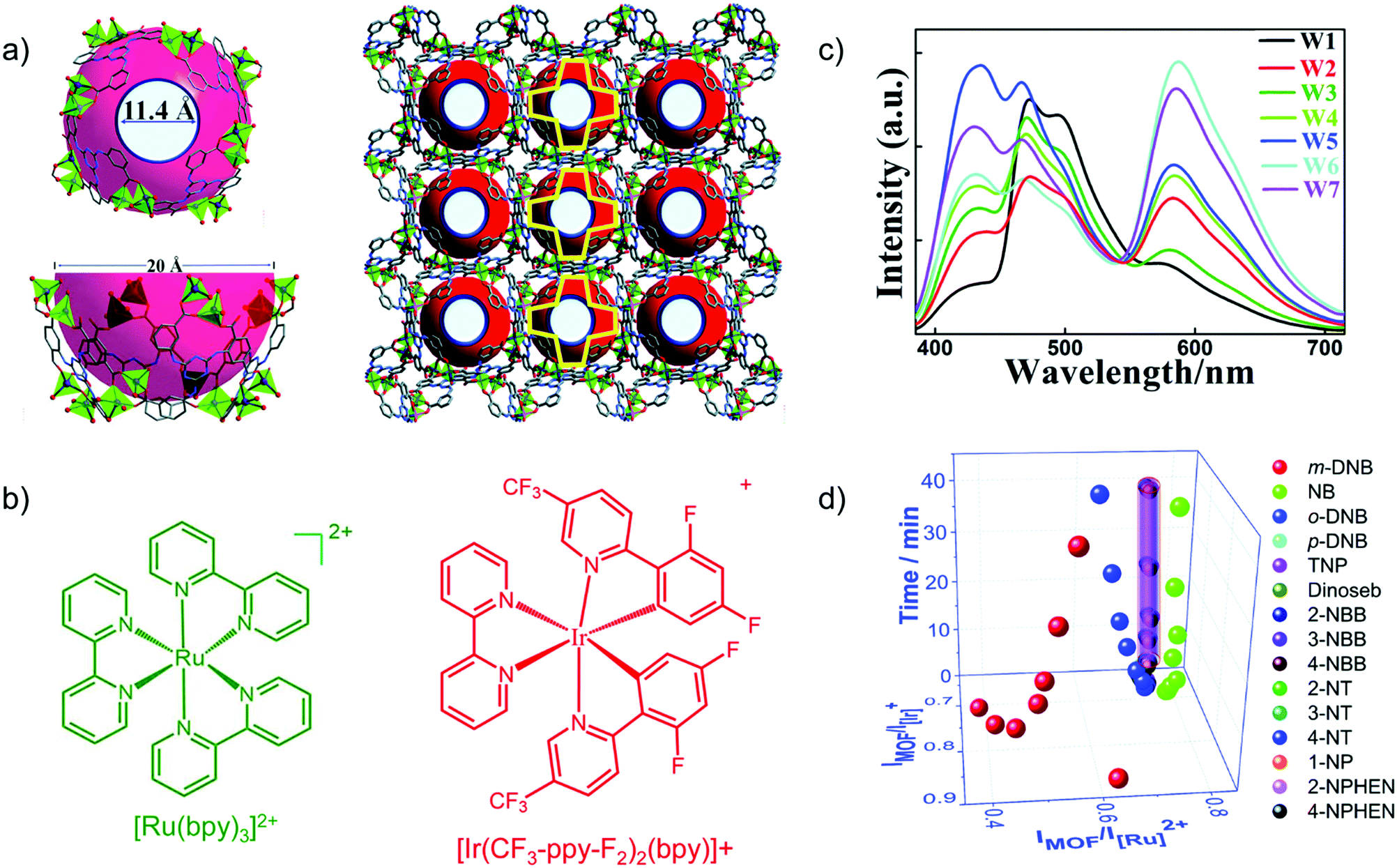 | ||
| Fig. 9 (a) Structure of Zn-MOF [DMA]2[Zn2(L)(H2O)] with the aperture and cage sizes. (b) Structures of [Ru(bpy)3]2+ and [Ir(CF3-ppy-F2)2(bpy)]+. (c) Emission spectra (λex = 365 nm) for loading different amounts of Ir- and Ru-complex guests in the Zn-MOF. W1:0.88/0.55 wt% Ir/Ru complex; W2:0.28/0.45; W3:0.18/0.25; W4:0.18/0.46; W5:0.13/0.35; W6:0.065/0.46; W7:0.065/0.42. (d) Derived 3D ratiometric sensing of nitroaromatics vapors with signal evolution time as the third dimension. Reproduced from ref. 78 with permission from the Royal Society of Chemistry, copyright 2018. | ||
6.4. QD-guest@LMOF
Quantum dots (QDs) are well-known to possess unique optical properties, such as high quantum yield, size-dependent luminescence, and low photobleaching. These unique features stem from the quantum confinement effect. Embedding or immobilizing QDs within a MOF matrix make it possible to improve the photochemical stability of QDs while retaining their unique luminescence properties79 and at the same time to introduce the QD photophysical properties into MOFs.80 Until now, semi-conductor QDs, carbon QDs as well as perovskite QDs have been utilized to construct QD-based LMOF multi-emitter composites.81Semi-conductor QDs were the earliest QDs to fabricate LMOF composite materials. Compared to semi-conductor QDs, carbon QDs (CDs) offer low toxicity, facile modification and excellent biocompatibility with similar luminescence properties.82
For example, blue-emitting nitrogen and sulfur co-doped CDs were encapsulated into the red-emitting LMOF [Eu(btc)(H2O)] (btc3− = 1,3,5-benzenetricarboxylate) to fabricate a dual-emitting Eu-MOF/N,S-CD composite.83 The composite showed different emission properties in the presence of DMF and in water. The encapsulated CDs aggregated in DMF at the cost of emission efficiency, and thus the dominant Eu3+-based emission made the composite red-emitting. While in water (as a high energy O–H oscillator), the Eu3+-based emission was quenched and the CDs released from aggregation displayed strong blue-emission. As the water content increased from 0% to 10% (v/v), the emission color changed from red to blue. Thus, the composite was suggested as a sensor for water detection in DMF. The ratio of the intensity of the emission at 420 (CDs) and 623 nm (Eu3+) increased linearly with the water content in DMF.
In recent years, perovskite QDs have developed rapidly due to their ultrahigh quantum yield and tunable emission wavelength over the entire visible spectrum.84 However, the main drawbacks of perovskite QDs are sensitivity to temperature, humidity and light. Porous MOFs have been demonstrated to stabilize perovskite QDs while maintaining their luminescence properties. The combination of perovskite QDs and Ln-LMOFs can be developed as a dual-emission material.
CH3NH3PbBr3 perovskite QDs were, for example, encapsulated into [Eu(btc)(H2O)] (btc3− = 1,3,5-benzenetricarboxylate) through a two-step synthetic process (Fig. 10).81 At first, PbBr2 was loaded into the Eu-MOF to form a PbBr2@Eu-MOF precursor, and then CH3NH3Br was reacted to form the CH3NH3PbBr3@Eu-MOF composite with the powder color changing from white to yellow. For the emission spectra of the composite, the characteristic Eu emission along with the band-edge emission of CH3NH3PbBr3 QDs was monitored. The emission peak of CH3NH3PbBr3 QDs was found at 513 nm after the QD encapsulation in the Eu-MOF. Under excitation from 365 to 254 nm, the emission color evolution was turned from green to red, in which QD-based emission was decreased along with the increased Eu3+-based emission. Additionally, under 317 nm excitation, a similar color variation was achieved through a temperature increase from 25 to 200 °C. These excitation wavelength-dependent and temperature-dependent emission properties of the CH3NH3PbBr3@Eu-MOF composite could be further applied in the anti-counterfeiting field.81
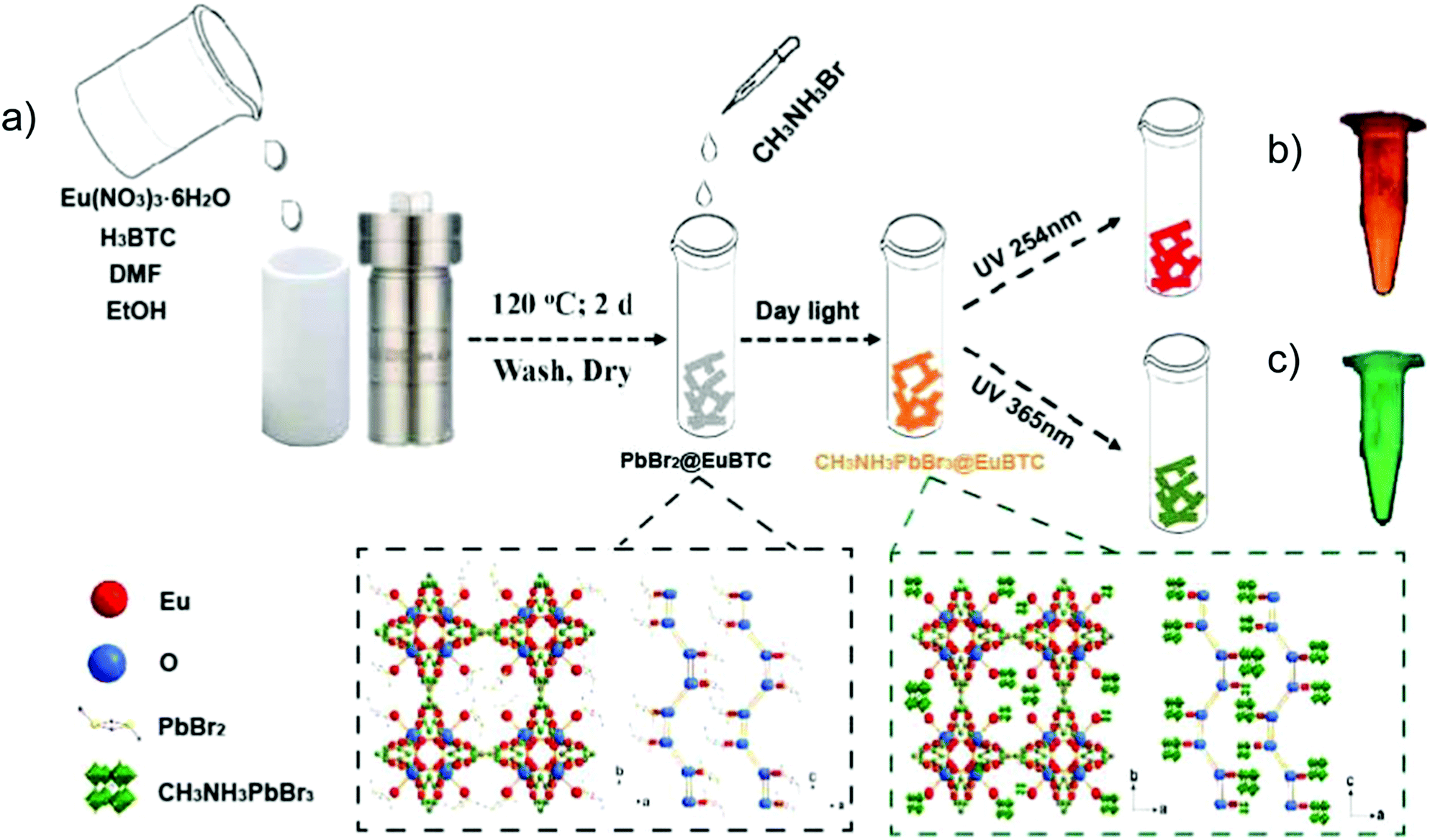 | ||
| Fig. 10 (a) Schematic illustration of the two-step fabrication of the CH3NH3PbBr3@Eu-MOF composite including the PbBr2@Eu-MOF precursor prepared by a solvothermal method, and further reaction with the addition of CH3NH3Br solution to the targeted CH3NH3PbBr3@Eu-MOF composite. The two dotted frames depict the crystal structures of PbBr2@Eu-MOF (left) and CH3NH3PbBr3@Eu-MOF (right) along the b and c axes. Optical images of CH3NH3PbBr3@Eu-MOF powder under a 254 nm (b) and 365 nm (c) UV lamp are shown as a comparison. Reproduced from ref. 81 with permission from the American Chemical Society, copyright 2018. | ||
7. Type V: multi-chromophore guest emitters in a non-luminescent MOF, chromophores@MOF
Apart from multiple emission of LMOFs where the metal or linker of the MOF are at least one emission source (vide supra), non-emissive MOFs can be utilized as containers to encapsulate multiple chromophore guests.34,85 This is an alternative way to construct multi-emitter LMOFs, such that the multiple emission comes solely from the multi-chromophore guests. Again, the encapsulated multi-chromophore guests can be prevented in the MOF host from aggregation-induced quenching as well as benefit from reduced non-radiative deactivation processes.As noted in the Introduction to Section 6 for Type IV chromophore@LMOF, we take “chromophore guests” to be species which are not part of the basic MOF but are incorporated post-synthetically or in situ during the MOF synthesis. The post-synthetic interaction of the chromophore guests can be non-covalent (supramolecular) or covalent (coordinative).
A case of in situ encapsulation was the incorporation of the organic dyes fluorescein (FL, green emitter) and rhodamine B (RhB, red-emitter) into the sodalite cage of ZIF-8 by a one pot synthesis (Fig. 11a).72 The resulting FL + RhB@ZIF-8 composite can emit a bright yellow color in the solid state. 3D printable composite pellets with white light emission were further gained by combining the yellow-emitter of FL + RhB@ZIF-8 with a blue-emitter of a photopolymer resin (Fig. 11b). The cool to warm white light emission (CCT: 8300 K → 3700 K) could be tuned by changing the 3D printed pellet thickness (Fig. 11c). The emission maxima of FL or RhB in their solution state were red-shifted in the FL + RhB@ZIF-8 solid solution and blue-shifted in the pellet composite. The red-shifted emission in FL + RhB@ZIF-8 can be ascribed to the encapsulated FL or RhB polarized by the surrounding interaction groups (e.g. –N–Zn–N linkage, H–C![[double bond, length as m-dash]](https://www.rsc.org/images/entities/char_e001.gif) C–H linker part) of ZIF-8. The guest molecules of FL and RhB possess hydrogen bonding and π–π stacking sites that are readily affected by the change in the surrounding environment leading to a shift in emission wavelength.
C–H linker part) of ZIF-8. The guest molecules of FL and RhB possess hydrogen bonding and π–π stacking sites that are readily affected by the change in the surrounding environment leading to a shift in emission wavelength.
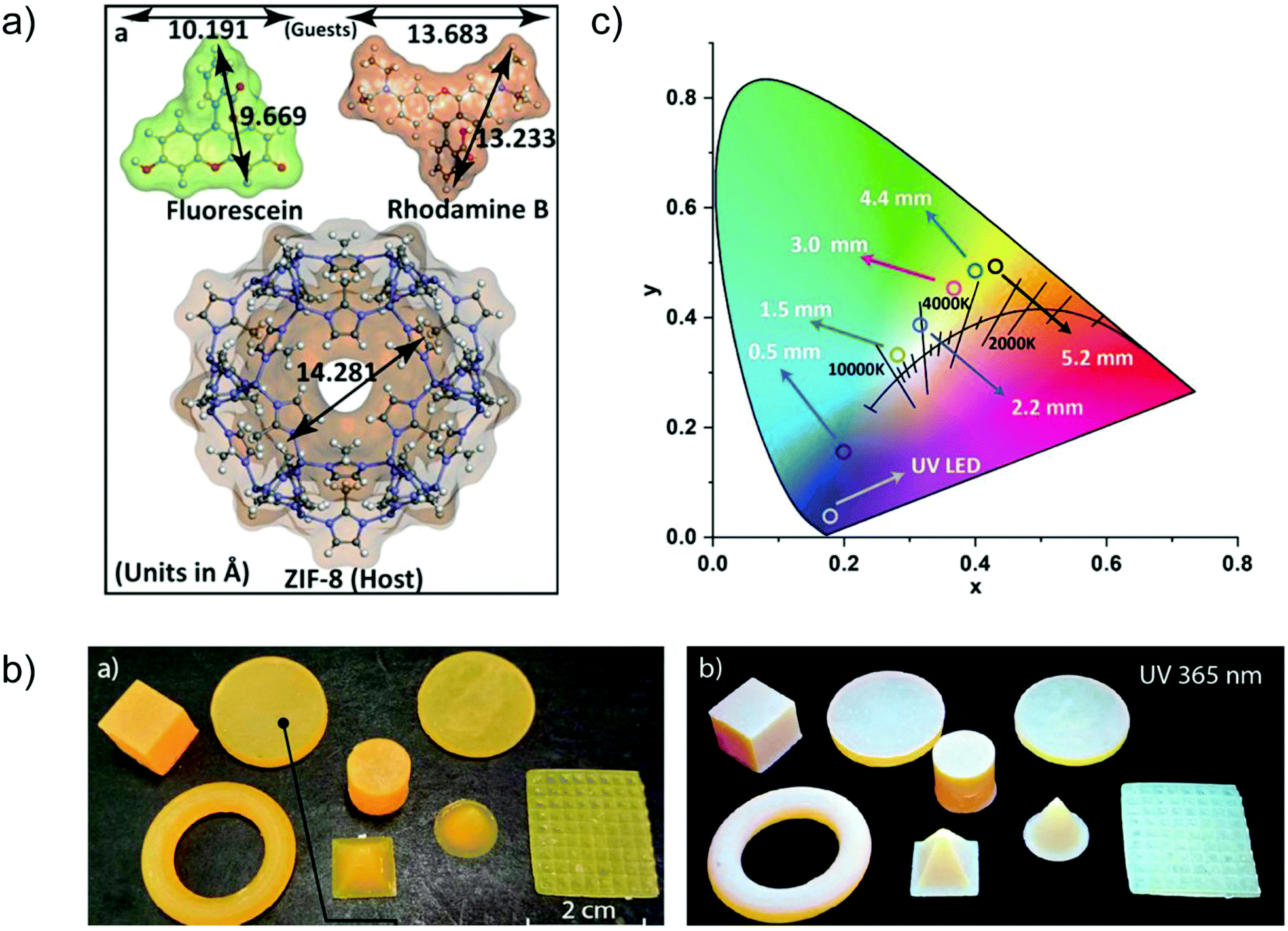 | ||
| Fig. 11 (a) Structural dimensions of the two fluorescent guest species FL and RhB, and the host framework of ZIF-8. (b) Various shapes of 3D printed objects constructed from FL + RhB@ZIF-8 dispersed in photopolymer resin, which emit white light under UV irradiation. (c) CIE coordinates corresponding to the cool to warm white light changed by tuning the pellet thickness (given in mm). Reproduced from ref. 72 with permission of John Wiley & Sons, Ltd, copyright 2020. | ||
An LMOF with multi-chromophore dyes@ZIF-8 was fabricated by in situ encapsulation of the red-emitter RhB, the green emitter FL and the blue emitter 7-amino-4-(trifluoromethyl)-coumarin (C-151).73 Yet, the multi-phase physical mixture of RhB@ZIF-8, FL@ZIF-8 and C-151@ZIF-8 gave the desired white light emission, while the strong energy transfer between the three dyes in the solid solution of RhB&FL&C-151@ZIF-8 decreased the efficiency of white light emission. The work also included core–shell-structured RhB@ZIF-8⊃FL@ZIF-8⊃C-151@ZIF-8 with RhB@ZIF-8 as the outermost shell (see below).
8. Type VI: multi-heterostructure LMOF emitters
The lattice matching between MOF materials with very similar topologies can be used to fabricate multi-heterostructure MOF composites. Such type of MOF composite can combine the luminescence of each constituting MOF phase with reduced emission interference between the phases.86 Because of the lattice matching of chemically different but topologically similar MOFs, the derived heterostructure does not show an even microscopically clearly visible interface and can macroscopically still be viewed as a single LMOF phase.8.1. Core–shell structured LMOF (shell)⊃LMOF (core)
The epitaxial growth of one LMOF (as shell) on the surface of another LMOF (as core) can fabricate a core–shell hierarchical multi-emitter LMOF (shell)⊃LMOF (core).87 The similar chemical properties of Ln3+ as well as its tendency to form the isostructural coordination networks enables the fabrication of a core–shell structured emitter LMOF⊃LMOF with multiple emission properties.43,88For example, core–shell structured [Eu(cpb)]0.5⊃[Tb(cpb)]0.5 (cpb3− = 1,4-carboxyphenylboronate) displayed a yellow emission color compared to the red emission of the solid solution multi-emitter [Tb0.5Eu0.5(cpb)].21 The identical 5D0 and 5D4 lifetime of the core–shell sample to that of the single [Eu(cpb)] and [Tb(cpb)] phase, respectively, as well as the constant emission intensity ratio of IEu/ITb over the temperature range clearly indicated the negligible intermetallic energy transfer in the core–shell sample. Whereas for the solid-solution sample, the reduced 5D4 lifetime compared to [Tb(cpb)], as well as the gradually decreased IEu/ITb as the temperature increased, indicated the presence of Tb3+ to Eu3+ energy transfer. Additionally, the core–shell heterostructure had a four times enhanced luminescence over that of the solid-solution sample.
In another example, a core–shell structure was fabricated by hierarchically encapsulating the fluorophore molecules FL and RhB into the cyclodextrin MOF, in which γ-cyclodextrins (γ-CD) are linked by K+ (Fig. 12b and c). The core–shell structured FL⊃RhB@CD-MOF, with epitaxially grown FL@CD-MOF (shell) on the surface of RhB@CD-MOF (core), exhibited a considerable spectral superposition with yellow emission (Fig. 12d). To gain the desired white light emission, 7-HCm@CD-MOF (HCm = 7-hydroxycoumarin) was prepared as a blue emission source to complement the yellow emission of FL⊃RhB@CD-MOF (Fig. 12e and f). Thus, the FL⊃RhB@CD-MOF as a seed crystal was further epitaxially grown over the 7-HCm@CD-MOF to form the core–shell structure of 7-HCm⊃FL⊃RhB@CD-MOF with white light emission.89
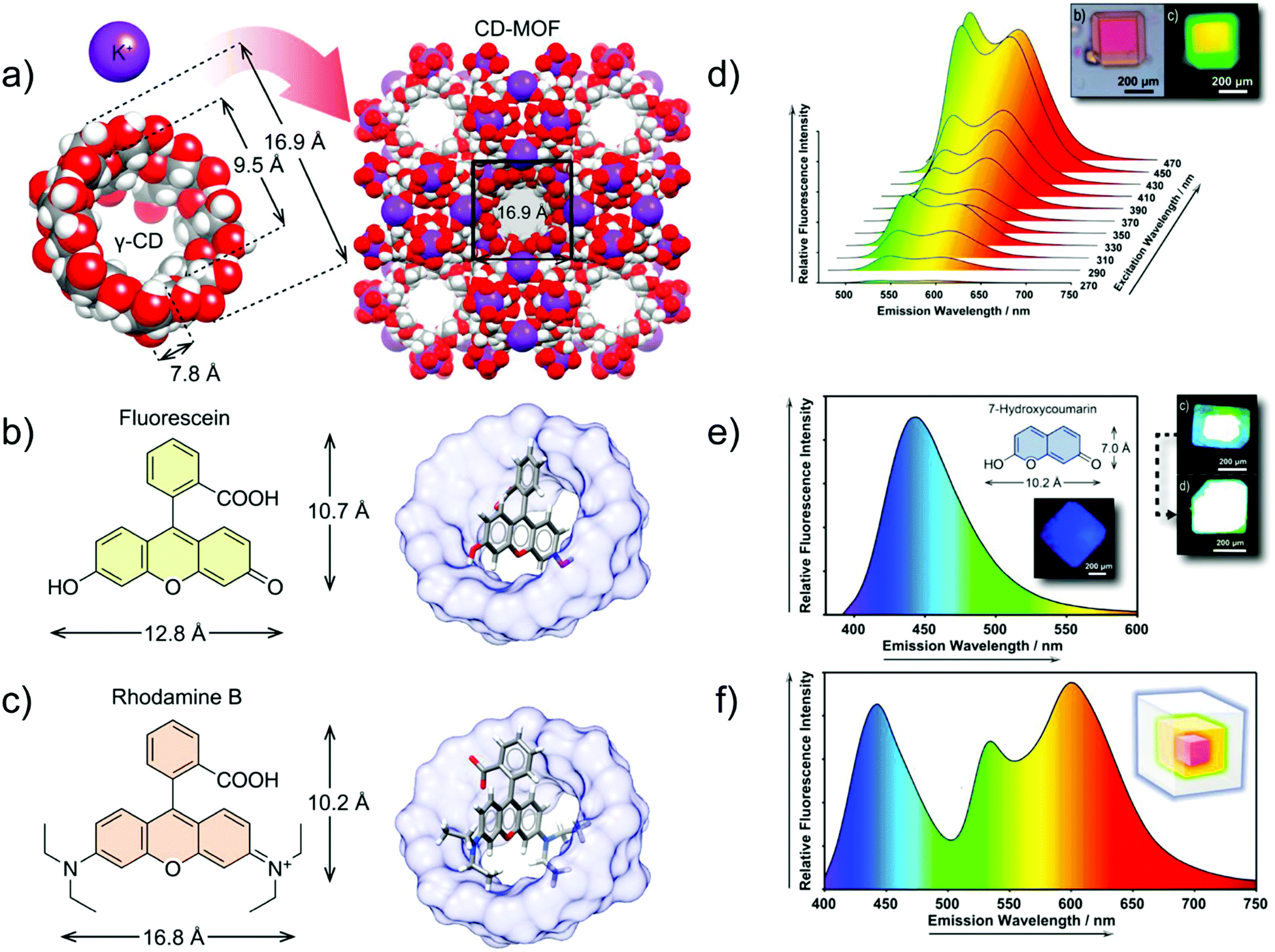 | ||
| Fig. 12 (a) Co-assembly process of γ-CDs and potassium ions for the formation of CD-MOF. (b) Chemical structure of FL (left) and structural model of FL@CD-MOF (right). (c) Chemical structure of RhB (left) and structural model of RhB@CD-MOF. (d) Emission spectrum of FL⊃RhB@CD-MOF, and microphotographs under a standard white light source (top left), and a UV light source (top right). (e) Emission spectrum of 7-HCm@CD-MOF (λex = 365 nm), chemical structure of 7-HCm (inset top), and microphotographs of 7-HCm@CD-MOF (inset down) and 7-HCm⊃FL⊃RhB@CD-MOF (top right) under a UV light source. (f) Fluorescence emission spectrum of 7-HCm⊃FL⊃RhB@CD-MOF (λex = 365 nm), and schematic representation of the three-layer core–shell structure with the respective emitting colors (inset). Reproduced from ref. 89 with permission from the American Chemical Society, copyright 2019. | ||
To complement the example of multi-chromophore dyes@ZIF-8 mentioned at the end of Section 7, the work also included multi-shell structured RhB@ZIF-8⊃FL@ZIF-8⊃C-151@ZIF-8.73 C-151@ZIF-8 as the core was overgrown by FL@ZIF-8, and the resulting core–shell structure was further overgrown by RhB@ZIF-8 to form multi-shell structured RhB@ZIF-8⊃FL@ZIF-8⊃C-151@ZIF-8. The efficient spatial separation between the three dyes yielded white light emission with high quantum yield, with further improvement over the multiphase physical mixture of RhB@ZIF-8, FL@ZIF-8 and C-151@ZIF-8 and the solid solution of RhB&FL&C-151@ZIF-8.
8.2. Nano-structured LMOF/LMOF thin films on substrates
The deposition or the oriented growth of MOF thin films on a substrate (SURMOFs) is interesting, e.g., for optical device fabrication.90,91 A controllable thickness of MOF thin film can be realized by the layer-by-layer assembly to form SURMOFs.92 Different LMOFs can be deliberately grown on top of each other, each as a MOF film to realize the multiple emission properties. The interlayer charge or energy transfer and thereby the desired emission properties can be tailored by the thickness of the MOF films.The deposition of a [Eu(btc)] (MOF-76) top layer on a [Tb(btc)] Tb-SURMOF bottom layer by the layer-by-layer (heterolayer) approach yielded heteroepitaxial Eu/Tb-SURMOF bilayers with the [010] direction parallel oriented to the quartz glass substrate (Fig. 13a).92 A series of [Eumc/Tb40c]-SURMOFs were fabricated by changing the number of [Eu(btc)] deposition cycles, hence [Eu(btc)] top layers (m = 0, 1, 6, 15, 40) on the [Tb(btc)]-SURMOF with 40 deposition cycles. Also, a series of solid-solution [EuxTb1−x(btc)]-SURMOFs (x = 2, 13, 23 and 39) was prepared by doping Eu into the [Tb(btc)]-SURMOF. Both thin SURMOF films yielded a tunable emission color (Fig. 13b and c). However, the intensity ratio of I700/I489 (where I700 and I489 corresponds to the main Eu- and Tb-based emission lines, respectively) in doped [EuxTb1−x(btc)]-SURMOF was much steeper than that in the [Eumc/Tb40c]-SURMOFs (Fig. 13d). Thus, the emission color is easier and more straightforward to modulate in layer-by-layer-SURMOFs with the spatially separated Eu- and Tb-emitters with well-defined interfaces.
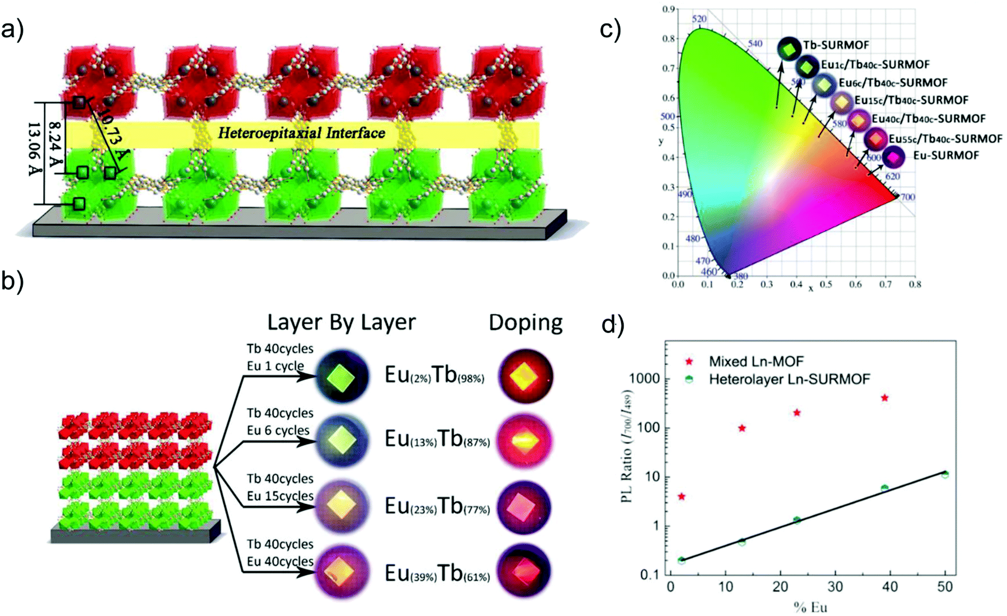 | ||
| Fig. 13 (a) Schematic drawing of the heteroepitaxial [Tb(btc)] (green) and [Eu(btc)] (red) MOF layers and interface with distinct Tb–Eu distances. (b) Eu/Tb-SURMOF (left) with the tailorable emission colors compared between the thin films fabricated by the layer-by-layer (heterolayer) approach as well as the solid-solution method of doping Eu into [Tb(btc)] in [EuxTb1−x(btc)]-SURMOF (right). (c) CIE chromaticity diagram showing the emission color of the heterolayer Eu/Tb-SURMOF from a different number of deposition cycles of Eu- or Tb-layers. (d) Ratio between the intensity of the 700 nm peak (Eu) and the intensity of the 489 nm peak (Tb) in solid solution [EuxTb1−x(btc)]-SURMOF and in heterolayer Eu/Tb-SURMOF. Reproduced from ref. 92 with permission of John Wiley & Sons, Ltd, copyright 2019. | ||
In a follow-up study, a three-component approach was carried out through a combination of RGB (red, green, blue) emitting Eu, Tb, and Gd containing layers in order to achieve white-light emission for solid-state white-lighting (SSWL) emitting devices. The devices showed CIE coordinates of ideal white light (0.33, 0.33) and close to the white point (0.37, 0.40) as well as CCT of 5614 K and 4411 K (Fig. 14).93
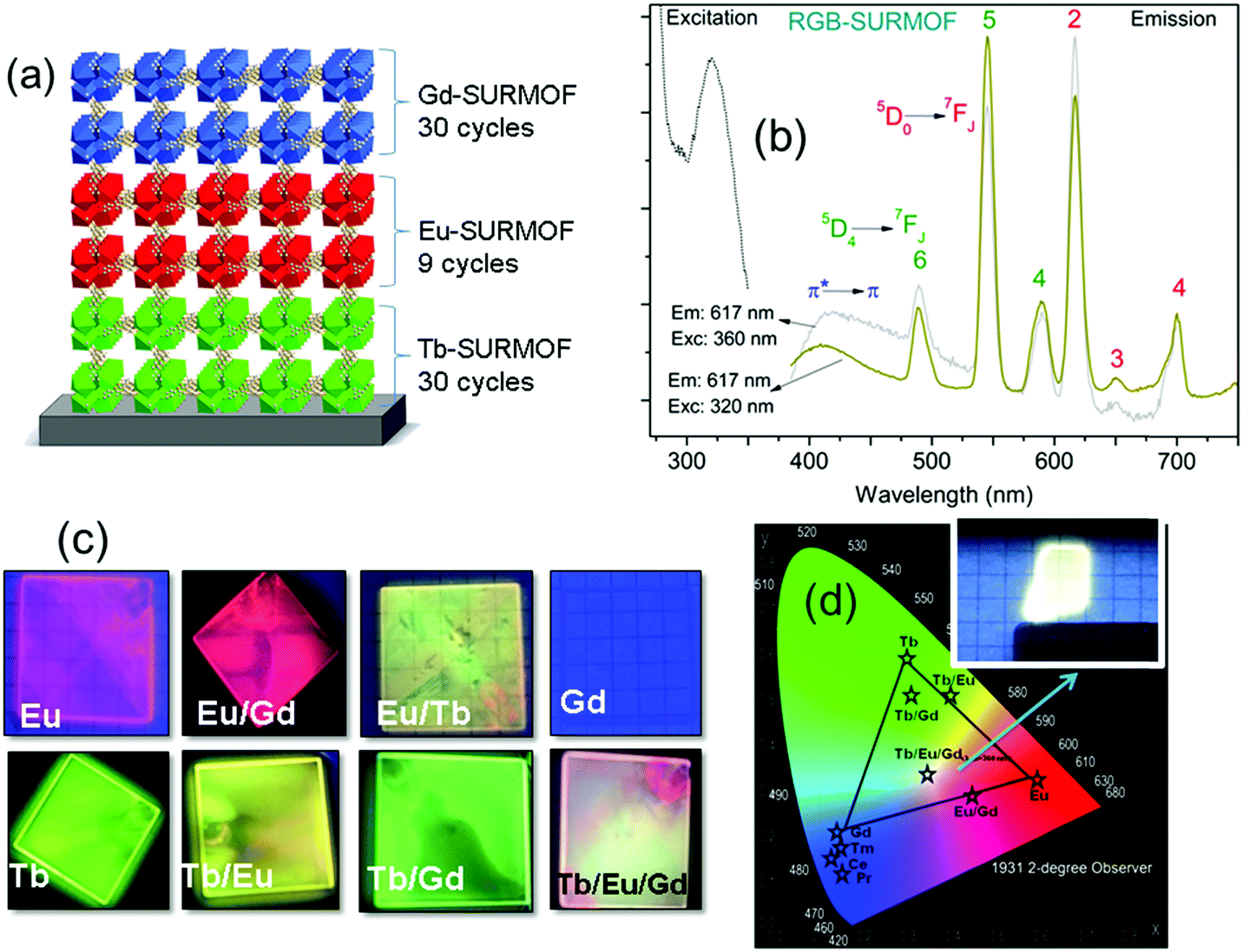 | ||
| Fig. 14 (a) Scheme of the SURMOF device composed by RGB layers. (b) Excitation and emission spectra of the white emitting RGB architecture of Tb/Eu/Gd-SURMOF (the excitation spectra were recorded by monitoring the emissions at 617 nm for RGB-SURMOF. The corresponding emission spectra were recorded at excitation wavelengths of 320 and 360 nm for RGB-SURMOF, respectively). (c) Fabricated SURMOFs of the individual elements, and the binary and the ternary RGB combinations. (d) CIE color x,y and a chromaticity diagram according to CIE of the individual element, and the binary and the ternary RGB optical devices.93 | ||
9. Conclusions
In this feature article, different concepts to design advanced luminescent materials of multi-emitter LMOFs are briefly addressed. Their potential applications, such as ratiometric sensing, light-emitting diodes, bioimaging, 3D printing and anticounterfeiting, are indicated. The six design strategies (summarized in this feature) for creating multi-emitter LMOFs can be classified into three concepts: (1) multiple emissive building blocks assemble into a single MOF phase; (2) single (L)MOF phase as a matrix support of chromophore guests; (3) more than one LMOF phase constitute heterostructured LMOFs. In the first concept, multiple emission can originate from its multi-emissive structural components, which include the metal-linker emitters (Type I) multi-metal emitters (Type II) and multi-linker emitters (Type III). The spatial allocation of the different emitters within the well-defined structure of LMOFs provides the possibility to control the homogeneous distribution, spatial distance and concentration ratio among the various chromophores in order to tune the energy transfer efficiency with the desirable multi-emission properties. The second concept, includes a chromophore incorporated into an already luminescent framework, chromophore@LMOF (Type IV) and multi-chromophores embedded into a non-emissive MOF, chromophores@MOF (Type V). Encapsulation of chromophores inside the MOF channels can efficiently prevent aggregation-induced quenching of the chromophores and form a solid-solution thereby enabling solution-like emission properties. Furthermore, non-radiative relaxation of chromophores can be minimized by encapsulation in MOFs due to rigidification by the confinement effect. The third concept of multi-heterostructure LMOF emitters (Type VI) refers to core–shell structured LMOF⊃LMOF and nano-structured LMOF/LMOF thin films on a substrate. The spatial separation among the different emitters in their own LMOF phase can retain their independent emission properties with less interference with the other emitters, which can avoid any unwanted energy transfer to obtain the desired multiple emission properties.The basic six design strategies summarized in this feature article, can be complemented by the combination of more than one (or two) atom, linker or chromophore type as emissive building blocks in the LMOF. Most of the multi-emitter LMOF work reported to date corresponds to binary emitters in an LMOF phase. Furthermore, rigid MOF structures are frequently used as the host matrix. Flexible MOFs have been reported to possess dynamic emission properties under external stimuli. Such flexible MOFs with stimuli-responsive luminescence could enable expanded multi-emission properties based on host–guest interactions.94,95 Also, the epitaxial growth of isostructural LMOFs by variation of different chromophore linkers with a similar linker length for creating the multi-heterostructure LMOF emitters has remained unexplored. Thus, there are ample more possibilities to create multi-emitter LMOFs which await to be explored for an interesting future of advanced multi-emitter materials.
Conflicts of interest
There are no conflicts to declare.Acknowledgements
S. X. acknowledges support from the Hoffmann Institute of Advanced Materials (HIAM), Shenzhen Polytechnic. C. J. acknowedges financial support by the Deutsche Forschungsgemeinschaft (DFG) within the Priority Program COORNET (SPP 1928, grant JA 466/43-1), as well as the within the Graduate College ModISC (GRK 2482, grant JA 466/40-1).Notes and references
- A. Kirchon, L. Feng, H. F. Drake, E. A. Joseph and H. C. Zhou, Chem. Soc. Rev., 2018, 47, 8611–8638 Search PubMed.
- M. D. Allendorf, C. A. Bauer, R. K. Bhakta and R. J. Houk, Chem. Soc. Rev., 2009, 38, 1330–1352 Search PubMed.
- K. Müller-Buschbaum, F. Beuerle and C. Feldmann, Microporous Mesoporous Mater., 2015, 216, 171–199 Search PubMed.
- Z. Hu, B. J. Deibert and J. Li, Chem. Soc. Rev., 2014, 43, 5815 Search PubMed.
- B. Yan, Acc. Chem. Res., 2017, 50, 2789–2798 Search PubMed.
- M. Pan, W. M. Liao, S. Y. Yin, S. S. Sun and C. Y. Su, Chem. Rev., 2018, 118, 8889–8935 Search PubMed.
- L. E. Kreno, K. Leong, O. K. Farha, M. Allendorf, R. P. Van Duyne and J. T. Hupp, Chem. Rev., 2012, 112, 1105–1125 Search PubMed.
- H. Wang, W. P. Lustig and J. Li, Chem. Soc. Rev., 2018, 47, 4729–4756 Search PubMed.
- R. Xu, Y. Wang, X. Duan, K. Lu, D. Micheroni, A. Hu and W. Lin, J. Am. Chem. Soc., 2016, 138, 2158–2161 Search PubMed.
- B. Yan, J. Mater. Chem. C, 2019, 7, 8155–8175 Search PubMed.
- Y. Cui, J. Zhang, H. He and G. Qian, Chem. Soc. Rev., 2018, 47, 5740–5785 Search PubMed.
- S. Wu, H. Min, W. Shi and P. Cheng, Adv. Mater., 2020, 32, e1805871 Search PubMed.
- W. Q. Zhang, Q. Y. Li, J. Y. Cheng, K. Cheng, X. Yang, Y. Li, X. Zhao and X. J. Wang, ACS Appl. Mater. Interfaces, 2017, 9, 31352–31356 Search PubMed.
- Q. Wang, Q. Liu, X. M. Du, B. Zhao, Y. Li and W. J. Ruan, J. Mater. Chem. C, 2020, 8, 1433–1439 Search PubMed.
- S. Y. Zhang, W. Shi, P. Cheng and M. J. Zaworotko, J. Am. Chem. Soc., 2015, 137, 12203–12206 Search PubMed.
- X. Liu, D. Xu, R. Lu, B. Li, C. Qian, P. Xue, X. Zhang and H. Zhou, Chem. – Eur. J., 2011, 17, 1660–1669 Search PubMed.
- Y. Rong, C. Wu, J. Yu, X. Zhang, F. Ye, M. Zeigler, M. E. Gallina, I. C. Wu, Y. Zhang, Y. H. Chan, W. Sun, K. Uvdal and D. T. Chiu, ACS Nano, 2013, 7, 376–384 Search PubMed.
- F. Wang and X. Liu, Acc. Chem. Res., 2014, 47, 1378–1385 Search PubMed.
- Y. Cui, Y. Yue, G. Qian and B. Chen, Chem. Rev., 2012, 112, 1126–1162 Search PubMed.
- H. Kaur, S. Sundriyal, V. Pachauri, S. Ingebrandt, K. H. Kim, A. L. Sharma and A. Deep, Coord. Chem. Rev., 2019, 401, 213077 Search PubMed.
- A. Abdallah, C. Daiguebonne, Y. Suffren, A. Rojo, V. Demange, K. Bernot, G. Calvez and O. Guillou, Inorg. Chem., 2019, 58, 1317–1329 Search PubMed.
- C. M. Balogh, L. Veyre, G. Pilet, C. Charles, L. Viriot, C. Andraud, C. Thieuleux, F. Riobe and O. Maury, Chem. – Eur. J., 2017, 23, 1784–1788 Search PubMed.
- A. M. Kaczmarek, Y. Y. Liu, C. Wang, B. Laforce, L. Vincze, P. Van Der Voort, K. Van Hecke and R. Van Deun, Adv. Funct. Mater., 2017, 27, 1700258 Search PubMed.
- X. Y. Xu, X. Lian, J. N. Hao, C. Zhang and B. Yan, Adv. Mater., 2017, 29, 1702298 Search PubMed.
- C. Dietl, H. Hintz, B. Rühle, J. Schmedt auf der Günne, H. Langhals and S. Wuttke, Chem. – Eur. J., 2015, 21, 10714–10720 Search PubMed.
- A. Das and D. M. D’Alessandro, Dalton Trans., 2016, 45, 6824–6829 Search PubMed.
- Y. Zhang, B. Li, H. Ma, L. Zhang and W. Zhang, J. Mater. Chem. C, 2017, 5, 4661–4669 Search PubMed.
- J. F. S. do Nascimento, A. M. U. de Araujo, J. Kulesza, A. F. D. Monteiro, S. Alves and B. S. Barros, New J. Chem., 2018, 42, 5514–5522 Search PubMed.
- G. Zeng, S. Xing, X. Wang, Y. Yang, D. Ma, H. Liang, L. Gao, J. Hua, G. Li, Z. Shi and S. Feng, Inorg. Chem., 2016, 55, 1089–1095 Search PubMed.
- J. Cornelio, T. Y. Zhou, A. Alkas and S. G. Telfer, J. Am. Chem. Soc., 2018, 140, 15470–15476 Search PubMed.
- Z. F. Wu, B. Tan, Z. H. Deng, Z. L. Xie, J. J. Fu, N. N. Shen and X. Y. Huang, Chem. – Eur. J., 2016, 22, 1334–1339 Search PubMed.
- Y. Cui, R. Song, J. Yu, M. Liu, Z. Wang, C. Wu, Y. Yang, Z. Wang, B. Chen and G. Qian, Adv. Mater., 2015, 27, 1420–1425 Search PubMed.
- Y. Wen, T. Sheng, X. Zhu, C. Zhuo, S. Su, H. Li, S. Hu, Q. L. Zhu and X. Wu, Adv. Mater., 2017, 29, 1700778 Search PubMed.
- Y. Tang, T. F. Xia, T. Song, Y. J. Cui, Y. J. Yang and G. D. Qian, Adv. Opt. Mater., 2018, 6, 1800968 Search PubMed.
- Z. N. Zhang, Z. Wei, F. Y. Meng, J. L. Su, D. Chen, Z. F. Guo and H. Z. Xing, Chem. – Eur. J., 2020, 26, 1661–1667 Search PubMed.
- Y. Yao, Z. Gao, Y. Lv, X. Lin, Y. Liu, Y. Du, F. Hu and Y. S. Zhao, Angew. Chem., Int. Ed., 2019, 58, 13803–13807 Search PubMed.
- Y. Chen, B. Yu, Y. Cui, S. Xu and J. Gong, Chem. Mater., 2019, 31, 1289–1295 Search PubMed.
- Y. Liu, X. Y. Xie, C. Cheng, Z. S. Shao and H. S. Wang, J. Mater. Chem. C, 2019, 7, 10743–10763 Search PubMed.
- H. Q. Yin and X. B. Yin, Acc. Chem. Res., 2020, 53, 485–495 Search PubMed.
- J. C. Bünzli and C. Piguet, Chem. Soc. Rev., 2005, 34, 1048–1077 Search PubMed.
- Y. Hasegawa, Y. Kitagawa and T. Nakanishi, NPG Asia Mater., 2018, 10, 52–70 Search PubMed.
- L. Li, Y. L. Zhu, X. H. Zhou, C. D. S. Brites, D. Ananias, Z. Lin, F. A. Almeida-Paz, J. Rocha, W. Huang and L. D. Carlos, Adv. Funct. Mater., 2016, 26, 8677–8684 Search PubMed.
- Y. F. Li, D. Wang, Z. Liao, Y. Kang, W. H. Ding, X. J. Zheng and L. P. Jin, J. Mater. Chem. C, 2016, 4, 4211–4217 Search PubMed.
- S. H. Xing, Q. M. Bing, L. F. Song, G. H. Li, J. Y. Liu, Z. Shi, S. H. Feng and R. R. Xu, Chem. – Eur. J., 2016, 22, 16230–16235 Search PubMed.
- Y. Wang, S. H. Xing, F. Y. Bai, Y. H. Xing and L. X. Sun, Inorg. Chem., 2018, 57, 12850–12859 Search PubMed.
- Y. Wang, S. H. Xing, X. Zhang, C. H. Liu, B. Li, F. Y. Bai, Y. H. Xing and L. X. Sun, Appl. Organomet. Chem., 2019, 33, e4898 Search PubMed.
- S. N. Zhao, L. J. Li, X. Z. Song, M. Zhu, Z. M. Hao, X. Meng, L. L. Wu, J. Feng, S.-Y. Song, C. Wang and H. J. Zhang, Adv. Funct. Mater., 2015, 25, 1463–1469 Search PubMed.
- Y. Q. Han, P. F. Yan, J. W. Sun, G. H. An, X. Yao, Y. X. Li and G. M. Li, Dalton Trans., 2017, 46, 4642–4653 Search PubMed.
- S. H. Xing, G. Zeng, X. M. Liu, F. Yang, Z. Q. Hao, W. Gao, Y. L. Yang, X. R. Wang, G. H. Li, Z. Shi and S. H. Feng, Dalton Trans., 2015, 44, 9588–9595 Search PubMed.
- L. V. Meyer, F. Schönfeld and K. Müller-Buschbaum, Chem. Commun., 2014, 50, 8093–8108 Search PubMed.
- R. F. D’Vries, S. Álvarez-García, N. Snejko, L. E. Bausá, E. Gutiérrez-Puebla, A. de Andrés and M. Á. Monge, J. Mater. Chem. C, 2013, 1, 6316–6324 Search PubMed.
- Y. Yang, L. Chen, F. Jiang, M. Yu, X. Wan, B. Zhang and M. Hong, J. Mater. Chem. C, 2017, 5, 1981–1989 Search PubMed.
- J. Wu, H. Zhang and S. Du, J. Mater. Chem. C, 2016, 4, 3364–3374 Search PubMed.
- J. Heine and K. Müller-Buschbaum, Chem. Soc. Rev., 2013, 42, 9232–9242 Search PubMed.
- S. H. Xing, T. Y. Bai, G. Zeng, G. H. Li, Z. Shi, S. H. Feng and R. R. Xu, ACS Appl. Mater. Interfaces, 2017, 9, 23828–23835 Search PubMed.
- G. Zeng, S. H. Xing, X. Han, B. J. Xin, Y. L. Yang, X. R. Wang, G. H. Li, Z. Shi and S. H. Feng, RSC Adv., 2015, 5, 40792–40797 Search PubMed.
- B. J. Xin, G. Zeng, L. Gao, Y. Li, S. H. Xing, J. Hua, G. H. Li, Z. Shi and S. H. Feng, Dalton Trans., 2013, 42, 7562–7568 Search PubMed.
- G. Zeng, S. H. Xing, X. R. Wang, Y. L. Yang, Y. Xiao, Z. H. Li, G. H. Li, Z. Shi and S. H. Feng, CrystEngComm, 2016, 18, 4336–4342 Search PubMed.
- G. Zeng, S. H. Xing, X. R. Wang, Y. L. Yang, D. X. Ma, H. W. Liang, L. Gao, J. Hua, G. H. Li, Z. Shi and S. H. Feng, Inorg. Chem., 2016, 55, 1089–1095 Search PubMed.
- H. Zhang, C. S. Lin, T. L. Sheng, S. M. Hu, C. Zhuo, R. B. Fu, Y. H. Wen, H. R. Li, S. D. Su and X. T. Wu, Chem. – Eur. J., 2016, 22, 4460–4468 Search PubMed.
- W. J. Newsome, S. Ayad, J. Cordova, E. W. Reinheimer, A. D. Campiglia, J. K. Harper, K. Hanson and F. J. Uribe-Romo, J. Am. Chem. Soc., 2019, 141, 11298–11303 Search PubMed.
- V. S. Padalkar and S. Seki, Chem. Soc. Rev., 2016, 45, 169–202 Search PubMed.
- A. C. Sedgwick, L. Wu, H. H. Han, S. D. Bull, X. P. He, T. D. James, J. L. Sessler, B. Z. Tang, H. Tian and J. Yoon, Chem. Soc. Rev., 2018, 47, 8842–8880 Search PubMed.
- L. Chen, C. Yan, M. Pan, H. P. Wang, Y. N. Fan and C. Y. Su, Eur. J. Inorg. Chem., 2016, 2676–2680 Search PubMed.
- L. Chen, J. W. Ye, H. P. Wang, M. Pan, S. Y. Yin, Z. W. Wei, L. Y. Zhang, K. Wu, Y. N. Fan and C. Y. Su, Nat. Commun., 2017, 8, 15985 Search PubMed.
- A. Halder, B. Bhattacharya, F. Haque, S. Dinda and D. Ghoshal, Chem. – Eur. J., 2019, 25, 12196–12205 Search PubMed.
- A. Douvali, A. C. Tsipis, S. V. Eliseeva, S. Petoud, G. S. Papaefstathiou, C. D. Malliakas, I. Papadas, G. S. Armatas, I. Margiolaki, M. G. Kanatzidis, T. Lazarides and M. J. Manos, Angew. Chem., Int. Ed., 2015, 54, 1651–1656 Search PubMed.
- Y. Dai, J. J. Zhang, S. Q. Liu, H. Zhou, Y. J. Sun, Y. Z. Pan, J. Ni and J. S. Yang, Chem. – Eur. J., 2018, 24, 9555–9564 Search PubMed.
- J. An, C. M. Shade, D. A. Chengelis-Czegan, S. Petoud and N. L. Rosi, J. Am. Chem. Soc., 2011, 133, 1220–1223 Search PubMed.
- X. L. Qu and B. Yan, Inorg. Chem., 2018, 57, 7815–7824 Search PubMed.
- H. Li, Q. Li and Z. Xu, J. Mater. Chem. C, 2019, 7, 2880–2885 Search PubMed.
- A. K. Chaudhari and J. C. Tan, Adv. Opt. Mater., 2020, 8, 1901912 Search PubMed.
- X. Y. Liu, K. Xing, Y. Li, C. K. Tsung and J. Li, J. Am. Chem. Soc., 2019, 141, 14807–14813 Search PubMed.
- J. Liu, Y. Zhuang, L. Wang, T. Zhou, N. Hirosaki and R. J. Xie, ACS Appl. Mater. Interfaces, 2018, 10, 1802–1809 Search PubMed.
- X. G. Yang, X. M. Lu, Z. M. Zhai, Y. Zhao, X. Y. Liu, L. F. Ma and S. Q. Zang, Chem. Commun., 2019, 55, 11099–11102 Search PubMed.
- M. K. Yu, Y. Xie, X. Y. Wang, Y. X. Li and G. M. Li, ACS Appl. Mater. Interfaces, 2019, 11, 21201–21210 Search PubMed.
- V. W. Yam, V. K. Au and S. Y. Leung, Chem. Rev., 2015, 115, 7589–7728 Search PubMed.
- H. Zhao, J. Ni, J. J. Zhang, S. Q. Liu, Y. J. Sun, H. Zhou, Y. Q. Li and C. Y. Duan, Chem. Sci., 2018, 9, 2918–2926 Search PubMed.
- Q. L. Zhu and Q. Xu, Chem. Soc. Rev., 2014, 43, 5468–5512 Search PubMed.
- J. Aguilera-Sigalat and D. Bradshaw, Coord. Chem. Rev., 2016, 307, 267–291 Search PubMed.
- D. Zhang, W. Zhou, Q. Liu and Z. Xia, ACS Appl. Mater. Interfaces, 2018, 10, 27875–27884 Search PubMed.
- J. Li, B. Wang, H. Zhang and J. Yu, Small, 2019, 15, 1805504 Search PubMed.
- Y. Dong, J. Cai, Q. Fang, X. You and Y. Chi, Anal. Chem., 2016, 88, 1748–1752 Search PubMed.
- J. Ren, T. Li, X. Zhou, X. Dong, A. V. Shorokhov, M. B. Semenov, V. D. Krevchik and Y. Wang, Chem. Eng. J., 2019, 358, 30–39 Search PubMed.
- Z. N. Zhang, Z. H. Wei, F. Y. Meng, J. L. Su, D. S. Chen, Z. F. Guo and H. Z. Xing, Chem. – Eur. J., 2020, 26, 1661–1667 Search PubMed.
- L. L. da Luz, B. F. Lucena Viana, G. C. O. da Silva, C. C. Gatto, A. M. Fontes, M. Malta, I. T. Weber, M. O. Rodrigues and S. A. Júnior, CrystEngComm, 2014, 16, 6914–6918 Search PubMed.
- M. L. Foo, R. Matsuda and S. Kitagawa, Chem. Mater., 2013, 26, 310–322 Search PubMed.
- M. Pan, Y. X. Zhu, K. Wu, L. Chen, Y. J. Hou, S. Y. Yin, H. P. Wang, Y. N. Fan and C. Y. Su, Angew. Chem., Int. Ed., 2017, 56, 14582–14586 Search PubMed.
- Y. F. Chen, B. Yu, Y. D. Cui, S. J. Xu and J. B. Gong, Chem. Mater., 2019, 31, 1289–1295 Search PubMed.
- R. Haldar, L. Heinke and C. Wöll, Adv. Mater., 2020, 32, 1905227 Search PubMed.
- J. L. Zhuang, D. Ar, X. J. Yu, J. X. Liu and A. Terfort, Adv. Mater., 2013, 25, 4631–4635 Search PubMed.
- D. H. Chen, R. Haldar, B. L. Neumeier, Z. H. Fu, C. Feldmann, C. Wöll and E. Redel, Adv. Funct. Mater., 2019, 29, 1903086 Search PubMed.
- G. E. Gomez, D.-H. Chen, B. L. Neumeier, J. C. C. Santos, A. E. Sedykh, V. Gvilava, R. Maile, C. Feldmann, C. Wöll, C. Janiak, K. Müller-Buschbaum and E. Redel, Adv. Mater. Interfaces, 2020 Search PubMed , in revision.
- S. Jensen, K. Tan, W. P. Lustig, D. S. Kilin, J. Li, Y. J. Chabal and T. Thonhauser, Chem. Mater., 2019, 31, 7933–7940 Search PubMed.
- Z. Wang, C. Y. Zhu, Z. W. Wei, Y. N. Fan and M. Pan, Chem. Mater., 2020, 32, 841–848 Search PubMed.
| This journal is © The Royal Society of Chemistry 2020 |