A dendrimer emitter doped in a dendrimer host: efficient thermally activated delayed fluorescence OLEDs with fully-solution processed organic-layers†
K.
Albrecht‡
 ab,
K.
Matsuoka‡
c,
K.
Fujita
*c and
K.
Yamamoto
 *ab
*ab
aLaboratory for Chemistry and Life Science, Tokyo Institute of Technology, 4259 Nagatsuta Midori-ku, Yokohama 226-8503, Japan. E-mail: yamamoto@res.titech.ac.jp
bJST-ERATO Yamamoto Atom Hybrid Project, Tokyo Institute of Technology, 4259 Nagatsuta Midori-ku, Yokohama 226-8503, Japan
cInstitute of Materials Chemistry and Engineering, Kyushu University, Kasuga, Fukuoka 816-8580, Japan. E-mail: katsuf@asem.kyushu-u.ac.jp
First published on 3rd April 2018
Abstract
A thermally activated delayed fluorescence (TADF) carbazole dendrimer (tBuG2TAZ) doped in a carbazole dendrimer host (G3Ph, G4Ph) was employed as an emissive layer (EML) in an OLED device with fully solution processed organic layers. Green (λMAX = 502 nm) emission with a maximum external efficiency (EQEMAX) of 16.1% was achieved when tBuG2TAZ was doped in G3Ph. This value was higher than the previously reported OLED device with a neat film of tBuG2TAZ as an EML because of the higher PLQY due to suppressed concentration quenching. The TADF-active carbazole dendrimer doped in a carbazole host film shows excellent miscibility and solvent resistance to ethanol. On the other hand, when a small molecule (rubrene) was doped in the carbazole dendrimer, significant dissolution of rubrene was observed after rinsing the doped film with ethanol. This shows the importance of the solvent resistivity of a dopant emitter when another film is solution-processed onto the doped film. The “doping dendrimer in dendrimer” concept is a new concept to allow fabrication of fully solution-processed TADF OLEDs.
Introduction
The emitting materials for organic light emitting diodes (OLEDs)1 are now reaching the 3rd generation, i.e., thermally-activated delayed-fluorescence (TADF) materials,2 after intense research on fluorescence1 and phosphorescence3 materials. TADF emitters are materials with a quite small singlet and triplet energy gap (less than about 0.4 eV) that enables the up conversion of the triplet excitons to singlet excitons with room temperature thermal energy. Accordingly, solution-processable TADF materials such as small molecules,4 polymers,5 dendrimers,6 and Cu complexes7 have been reported. Most of these reports describe vacuum depositing the electron transporting layer on the solution-processed emitting (TADF) layer, and only a few reports are about forming all organic layers by a solution-process.5g,8 However, to fabricate a solution-processed OLED device that allows cheap and large size displays, all materials including the electrodes have to be solution-processed.Dendrimers9 are a type of polymer material that has a single molecular weight and a perfectly branched structure. Generally, dendrimers have a high-molecular weight (over 1000) and form amorphous films through solution-processing.10 Additionally, they have high solubility, high purity, no structural defects, and no batch-to-batch variability, which can be an advantage compared to conventional polymer materials.
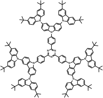
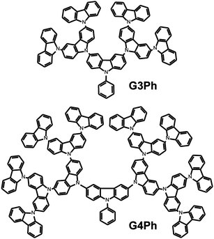
The basic design principle of TADF materials is to separate the HOMO and LUMO on the molecule to decrease the singlet to triplet energy gap (ΔEST). At the same time, to obtain a reasonable radiation rate constant, the HOMO and LUMO need some overlap.11 Based on this design principle, several donor–acceptor dyads with appropriate linker molecules have been reported.2b,d,e Previously, we have reported that carbazole dendrimers12 have an intrinsically separated HOMO and LUMO, i.e., the HOMO is localized at the outer-layer and the LUMO is localized at the inner-layer of the molecule.12a Attachment of acceptor molecules to the inner layer of dendritic carbazoles will efficiently separate the HOMO and LUMO, which results in a small ΔEST. Actually, an efficient TADF material with one 2nd generation dendritic carbazole unit was first reported by Adachi's group.13 Independently, we have developed 2nd to 4th generation triazine core trisubstituted carbazole dendrimers as the first solution-processable and neat usable TADF emitters.6a Following our report, many carbazole dendrimer containing donor–acceptor systems were reported as solution processable TADF materials.6 Most recently, we have succeeded in constructing TADF-OLEDs with fully solution-processed organic layers, where the neat films of carbazole dendrimers were used as non-doped emissive layers (EMLs), through an orthogonal solvent (OS) method.8a,b Although the maximum external quantum efficiency (EQEMAX) of this OLED device approaches 10%, the bottle neck was the low photoluminescence quantum efficiency (PLQY) of the neat film due to some concentration quenching. To solve this problem, here we propose the unique design concept of a doped EML for TADF-OLEDs that consists of a TADF active carbazole dendrimer (Chart 1) and a carbazole dendrimer host (Chart 2). This combination allows high photoluminescence quantum yield (PLQY) and good resistivity toward alcohols, which leads to successful lamination of the electron transporting material on the EML and fabrication of efficient TADF-OLEDs with fully solution processed organic layers.
Results and discussion
To fabricate a TADF-OLED with entirely solution-processed organic-layers by the OS method, the key issue is to design an alcohol-resistive EML because some of the organic materials for the electron-transporting layer (ETL), such as TPBi (2,2′,2′′-(1,3,5-benzinetriyl)-tris(1-phenyl-1-H-benzimidazole)),14 BPOBP (1,3-bis(3-(diphenylphosphoryl)phenyl)benzene),14 and SPPO13 (2,7-bis(diphenylphosphoryl)-9,9′-spirobi[fluorene]),15 are processable from alcohol solutions. As the all-carbazole dendrimer host–guest EML, phenyl substituted carbazole dendrimers (GnPh, n = generation, Chart 2)16 and terminal substituted carbazole-triazine G2 dendrimers (tBuG2TAZ, Chart 1) were chosen since both materials were previously reported as alcohol (ethanol) resistant EML materials.8a,16 The triplet energy level (T1) of these hosts are both 2.90 eV which is large enough to dope tBuG2TAZ dendrimers (T1 = 2.62 eV). This combination is expected to suppress the concentration quenching of tBuG2TAZ. Additionally, due to the structural similarity of these dendrimers they can be assumed to have excellent miscibility in the mixed thin film.Photophysical properties
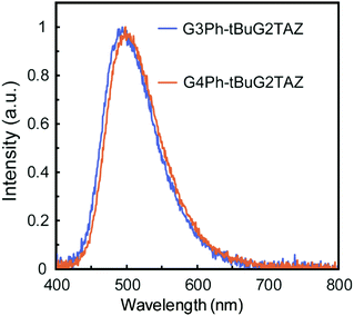
The PLQY and the energy levels of tBuG2TAZ doped in GnPh (n = 2–4) matrices were evaluated. The PLQY of the neat film of the tBuG2TAZ dendrimer (Φ = 0.44) was reported to be lower than that in dilute toluene solution (Φ > 0.9) due to concentration quenching. GnPh films doped with 5, 10, 15, 20, 30 and 50 wt% of tBuG2TAZ were prepared by spin coating from the corresponding toluene solutions. AFM analysis confirmed the smooth surface of the mixed film (15 wt%, Fig. S1, ESI†) suggesting that the dendritic host and guest are well-miscible with each other. All mixed films showed only green emission from tBuG2TAZ (guest) around 500 nm (Fig. 1). The PLQY reached the maximum value (Φ = 0.72–0.85) when the tBuG2TAZ concentration was 10–15 wt% (Table S1, ESI†). The PL spectra showed a hypsochromic shift when the doping concentration decreased, and the corresponding S1 energy determined from the onset of the PL spectra increased (Fig. S2 and Table S2, ESI†). The emission should be based on the transition in the charge-transfer (CT) state as judged by the broad and structureless PL feature, and the spectral shift can be attributed to the change in polarity of the environment. The polarity of tBuG2TAZ should be higher than that of GnPh. The S1 energy became lower when the generation of GnPh increased at an identical doping concentration. This result probably reflects the higher polarity of higher generation GnPh due to the summation of the dipole moment of carbazole units.12a![[thin space (1/6-em)]](https://www.rsc.org/images/entities/char_2009.gif) § The ΔEST value of tBuG2TAZ (15 wt%) in the host was evaluated by comparing the fluorescence spectra at room temperature and phosphorescence spectra at 77 K (Fig. S3, ESI† and Table 1). The ΔEST values were estimated to be 0.07 eV (G3Ph) and 0.09 eV (G4Ph), respectively. These values were close to that of the tBuG2TAZ neat film (0.07 eV) and small enough for reverse intersystem crossing (TADF expression).
§ The ΔEST value of tBuG2TAZ (15 wt%) in the host was evaluated by comparing the fluorescence spectra at room temperature and phosphorescence spectra at 77 K (Fig. S3, ESI† and Table 1). The ΔEST values were estimated to be 0.07 eV (G3Ph) and 0.09 eV (G4Ph), respectively. These values were close to that of the tBuG2TAZ neat film (0.07 eV) and small enough for reverse intersystem crossing (TADF expression).
To further investigate the effect of doping tBuG2TAZ in the GnPh host, transient PL decay measurements were performed (Fig. 2 and Fig. S7, ESI†). The data at 300, 200, and 100 K are clearly showing the decay profile that is typical for TADF materials, i.e., the increase in the μs order long lifetime component upon increasing the temperature. It was difficult to estimate the accurate photophysical parameters from the decay curve because the ΦISC value cannot be estimated accurately due to the low PLQY. However, the ΦISC value should be in the range of ΦTADF < ΦISC < (1 − ΦF). Using this ΦISC value the ranges of kISC and kRISC were calculated using the previously reported equations (Table 2, see the ESI† for the equations) by assuming that kSr, kSnr, and kISC are significantly larger than kTnr and kRISC.17 It was difficult to compare the kRISC value between different host matrices, because the values were similar, but if we assume that kISC (or ΦISC) is identical in all matrices,18 the kRISC in G3Ph was the highest. G4Ph showed a slightly lower value and the neat film had the lowest kRISC value. The 3LE states of tBuG2TAZ are assumed to be similar to the T1 energy of the donor and acceptor fragments (carbazole dendron and triazine). The T1 energy of tert-butyl carbazole G2 dendron with a phenyl group was reported to be 2.96 eV,19 and the T1 of the NH free dendron was 2.89 eV in PMMA (see Fig. S4, ESI†). The T1 energy of triphenyltriazine is reported to be 3.03 eV.20 This means that the 3CT state (Table 1) of tBuG2TAZ is lying under the 3LE state and the gap is smaller when it is doped in G3Ph compared to G4Ph or the neat film. Recently it was discussed that a smaller 3CT–3LE gap will increase the vibronic coupling and accelerate the RISC process.21 Our observation matches this trend. However, it has to be noted that the 1CT level (ΔEST) that affects kRISC is also changing. Furthermore, the T1 energy of the neat tert-butyl carbazole G2 dendron (2.75 eV) was lower than when it was dispersed in PMMA (2.89 eV) probably due to the intermolecular interaction. Usually the 3LE state is treated as independent of the matrix. Our result indicates that the emitter in the doped film and the neat film can have different electronic states. Therefore, the actual 3LE energy in the neat film needs further consideration. The difference in kRISC of the doped and neat films is too small to explain the difference in PLQY if other parameters are constant. The low PLQY of the neat film can be attributed to the intermolecular interaction that increases non-radiative deactivation such as the triplet-concentration quenching process.22 Overall, the dispersion of tBuG2TAZ in GnPh not only suppresses concentration quenching but also affects the energy levels and the RISC process.
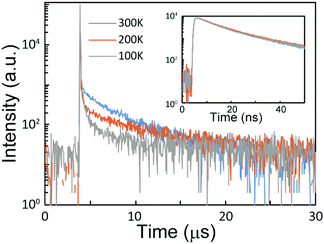 | ||
| Fig. 2 Transient decay spectra of the 15% tBuG2TAZ doped G3Ph film under vacuum at 300 K, 200 K, and 100 K. Inset is the data measured at a short time range. | ||
| Host | Φ | τ p [ns] | τ d [ns] | Φ p | Φ d | k p (107) [s−1] | k d (105) [s−1] | k ISC (107) [s−1] | Φ ISC | k RISC (105) [s−1] |
|---|---|---|---|---|---|---|---|---|---|---|
| a The prompt fluorescence decay rate (kp), intersystem crossing decay rate from S1 to T1 (kISC), and reverse intersystem crossing decay rate from S1 to T1 (kRISC) are calculated from Φ, ΦF, Φd, τF, and τd according to ref. 17 by assuming ΦTADF < ΦISC < (1 − Φp). b Reanalyzed using the data reported in ref. 8a. c An average lifetime calculated by τav = ∑Aiτi2/∑Aiτi, where Ai is the pre-exponential for lifetime τi. | ||||||||||
| G3Ph | 0.76 | 12.3 | 3941 | 0.44 | 0.32 | 8.1 | 2.5 | 2.6–4.5 | 0.32–0.56 | 3.3–5.8 |
| G4Ph | 0.70 | 13.2 | 4072 | 0.40 | 0.27 | 7.6 | 2.5 | 2.1–4.4 | 0.28–0.58 | 2.9–5.9 |
| None (neat)b | 0.44 | 13.3 | 5292c | 0.30 | 0.14 | 7.5 | 1.9 | 1.1–5.3 | 0.14–0.70 | 1.3–6.3 |
Solvent resistivity of the dendrimer films
Deposition of the alcohol-soluble ETL material onto the EML without significant damaging of the preceding layer is one of the important processes to establish OLEDs with fully solution-processed organic layers. We have previously reported that dendrimers having a relatively high molecular weight show resistance to ethanol, whereas a film of lower molecular weight was washed away.8a,b,16 The GnPh film doped with 15 wt% tBuG2TAZ was prepared on a glass substrate and the UV-vis spectrum before and after rinsing with ethanol was measured (Fig. S5, ESI†). The high molecular weight host showed resistance to ethanol, i.e., the G2Ph film doped with tBuG2TAZ was severely dissolved by ethanol but the G3Ph and G4Ph films remained almost unchanged. In order to understand the importance of using high molecular weight dendrimer dopants, a film of G3Ph doped with 10 wt% rubrene was also examined as a control experiment. Rubrene is a small molecular fluorescent dopant with a molecular weight of 533. As shown in Fig. S6 (ESI†), its thin neat film was strongly dissolved by ethanol rinsing even though rubrene is poorly soluble in ethanol. In the case of the G3Ph film doped with rubrene, the intensities of the characteristic peaks of rubrene around 500–550 nm were significantly reduced by rinsing. These results suggest that even if the host matrix is alcohol-resistant, the solvent infiltrates the host matrix and extracts the dopant to some extent. Such a phenomenon is unfavourable since strict control of the host–guest ratio is often required to maximize OLED performance. As pointed out previously, the molecular weight of aromatic compounds has a correlation with alcohol resistivity of the corresponding thin (nanometer scale) film where a molecular weight of >∼800–1000 ensures good alcohol resistivity.14 We have recently reported that this trend is true for a small molecular TADF emitter.8b The solubility test of the GnPh-emitter film emphasizes that the solubility control of both the host and dopant emitter is important.OLED device performance
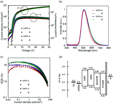
An OLED device with the 15 wt% tBuG2TAZ doped GnPh film as an emissive layer was fabricated and evaluated (Fig. 3, Table 3 and Table S3, ESI†). The first device structure was ITO/PEDOT-PSS (50 nm, spin-coated)/15 wt% tBuG2TAZ in GnPh (30 nm, spin-coated)/SPPO13(40 nm, vacuum deposition)/LiF (0.5 nm)/Al (80 nm) (device A) where PEDOT-PSS is the hole-injection layer, the dendrimer layer is the EML, and SPPO13 is the ETL. Another device with the solution-processed SPPO13 layer was also fabricated (device B, the basic device structure was the same as device A).| Host | EQEMAX, @100 cd m−2, @1000 cd m−2 [%] | V ON [V] | PEmax [lm W−1] | CEmax [cd A−1] | L MAX [cd m−2] | λ EL,max [nm] | CIE (x, y) | |
|---|---|---|---|---|---|---|---|---|
| G3Ph | A | 8.6, 8.0, 2.7 | 2.9 | 19.3 | 22.7 | 1182 | 503 | 0.28, 0.48 |
| B | 16.1, 15.9, 10.2 | 2.5 | 43.5 | 42.7 | 2003 | 502 | 0.28, 0.49 | |
| G4Ph | A | 10.5, 9.9, 4.9 | 2.9 | 27.3 | 28.6 | 1467 | 508 | 0.29, 0.51 |
| B | 16.0, 14.8, 8.1 | 2.6 | 44.1 | 44.1 | 1681 | 511 | 0.30, 0.51 | |
The EQEMAX of device A reached 8.6% (G3Ph host) and 10.6% (G4Ph host) with relatively large roll off (more than 50% at 1000 cd m−2). The EL spectra of all devices were almost identical to the PL spectra of the emitting layer. This indicates that the charge recombination effectively occurs in the EML. The EQEMAX is clearly exceeding the theoretical limit of a device that only harvests singlet excitons (5 to 7.5% with light out-coupling efficiency of 0.2 to 0.3). Therefore, it is concluded that the tBuG2TAZ doped GnPh EMLs harvest triplet excitons.
The EQEMAX of the OLED devices with entirely solution-processed organic layers (device B) has reached 16.1% (G3Ph host) and 16.0% (G4Ph host). The roll-off was significantly smaller, along with higher EQE values, improved power efficiency (PE) and current efficiency (EQE), and lowered turn-on voltage, suggesting that the carrier balance in device B is improved in comparison to device A, likely due to the inter-layer mixing between the EML and the ETL during the deposition of SPPO13 with the solution process.23 It should be noted that the improvement in OLED performance of the entirely solution-processed device can be well reproduced (see, Table S3, ESI† for the average device performance of 5 devices). The EL spectrum was almost the same as for device A, but had slightly broadened at the longer wavelength, which may indicate the influence of some interlayer-mixing between the EML and ETL.
Conclusions
In conclusion, an OLED device with fully-solution-processed organic layers was fabricated by employing a TADF dendrimer (tBuG2TAZ) doped carbazole dendrimer host (GnPh) as an EML. EQEMAX over 16% was reached due to high PLQY of the doped film. The effectiveness of doping the dendrimer emitter into the dendrimer host for further lamination of the ETL from alcohol was confirmed. A small molecule guest (rubrene) was washed out from the alcohol (ethanol)-resistive host matrix after rinsing with ethanol, but the dendrimer guest remained almost intact. The unique design concept of “doping dendrimer in dendrimer” for alcohol-resistive and TADF-active doped EMLs was proved here to be an effective way to fabricate OLEDs with entirely solution-processed organic multilayers and good device performance. Further research to understand the accurate photophysical mechanism and to design a more efficient solution-processable TADF material is now under investigation.Experimental
Chemicals
All chemicals were purchased from Kanto Kagaku Co., Ltd, TCI chemicals or Aldrich and used without further purification unless otherwise noted (solvents for spectroscopic studies were of spectroscopic grade, and solvents for the reactions and device fabrication were of dehydrated grade). SPPO13 (sublimed grade) was purchased from Lumtec. Carbazole dendrimer hosts,12a and tBuG2TAZ8a were prepared according to the literature.General
The UV-vis spectra were recorded using a Shimadzu UV-3150 spectrometer at room temperature. The room temperature fluorescence spectra and the fluorescence quantum yields were measured using a Hamamatsu Photonics C9920-02 absolute PL quantum yield measurement system (excitation wavelength: 380 nm). The fluorescence and phosphorescence spectra for the ΔEST determination were measured using a HORIBA JOBIN YVON FluoroMax-4 spectrometer (excitation wavelength: 365 nm), and the sample temperature was controlled with an Optistat DN (Oxford instruments). The PL lifetime measurements were performed using a Hamamatsu photonics fluorescence lifetime spectrometer C11367 (Quantaurus-Tau, excitation wavelength of 365 nm, and the sample temperature was controlled using an Optistat DN (Oxford Instruments)). The HOMO level of the materials was measured by photoelectron yield spectroscopy in air using an AC-2 (Riken Keiki). Atomic force microscopy (AFM) experiments were carried out using a Nanopics 1000 (Seiko instruments).Vacuum deposition was carried out under a pressure of <1 × 10⁻⁴ Pa. All devices with a device area of 4 mm2 were sealed using a sealing glass and an epoxy resin under inert conditions before measurements. The current density J, voltage V and luminance L characteristics of the OLEDs were measured using a DC voltage current source/monitor (6241A, ADCMT) and a luminance colorimeter (BM-5A, Topcon). Electroluminescence spectra were recorded using a photonic multichannel analyzer (PMA-11, Hamamatsu Photonics).
Conflicts of interest
There are no conflicts to declare.Acknowledgements
This work was supported by the Dynamic Alliance for Open Innovation Bridging Human, Environment and Materials, Grant-in-Aid for Scientific Research on Innovated Areas “π-System Figuration: Control of Electron and Structural Dynamism for Innovative Functions”, JSPS KAKENHI Grant Numbers 17H05146 and 15H05757, and by the research grant from The Murata Science Foundation.Notes and references
- C. Tang and S. A. VanSlyke, Appl. Phys. Lett., 1987, 51, 913–915 CrossRef CAS.
- (a) A. Endo, M. Ogasawara, A. Takahashi, D. Yokoyama, Y. Kato and C. Adachi, Adv. Mater., 2009, 21, 4802 CrossRef CAS PubMed; (b) H. Uoyama, K. Goushi, K. Shizu, H. Nomura and C. Adachi, Nature, 2012, 492, 234 CrossRef CAS PubMed; (c) J. C. Deaton, S. C. Switalski, D. Y. Kondakov, R. H. Young, T. D. Pawlik, D. J. Giesen, S. B. Harkins, A. J. Miller, S. F. Mickenberg and J. C. Peters, J. Am. Chem. Soc., 2010, 132, 9499–9508 CrossRef CAS PubMed; (d) M. Wong and E. Zysman-Colman, Adv. Mater., 2017, 1605444 CrossRef PubMed; (e) Z. Yang, Z. Mao, Z. Xie, Y. Zhang, S. Liu, J. Zhao, J. Xu, Z. Chi and M. Aldred, Chem. Soc. Rev., 2017, 46, 915–1016 RSC.
- M. A. Baldo, D. F. OÏBrien, Y. You, A. Shoustikov, S. Sibley, M. E. Thompson and S. R. Forrest, Nature, 1998, 395, 151–154 CrossRef CAS.
- (a) Y. Cho, K. Yook and J. Lee, Adv. Mater., 2014, 26, 6642 CrossRef CAS PubMed; (b) R. Komatsu, H. Sasabe, S. Inomata, Y.-J. Pu and J. Kido, Synth. Met., 2015, 202, 165 CrossRef CAS; (c) Y. Suzuki, Q. Zhang and C. Adachi, J. Mater. Chem. C, 2015, 3, 1700 RSC; (d) Y. Kim, C. Wolf, H. Cho, S. Jeong and T. Lee, Adv. Mater., 2016, 28, 734 CrossRef CAS PubMed; (e) Y. Cho, B. Chin, S. Jeon and J. Lee, Adv. Funct. Mater., 2015, 25, 6786 CrossRef CAS; (f) C. Tang, T. Yang, X. Cao, Y. Tao, F. Wang, C. Zhong, Y. Qian, X. Zhang and W. Huang, Adv. Opt. Mater., 2015, 3, 786 CrossRef CAS; (g) L. Mei, J. Hu, X. Cao, F. Wang, C. Zheng, Y. Tao, X. Zhang and W. Huang, Chem. Commun., 2015, 51, 13024 RSC; (h) Y. Wada, K. Shizu, S. Kubo, K. Suzuki, H. Tanaka, C. Adachi and H. Kaji, Appl. Phys. Lett., 2015, 107, 183303 CrossRef; (i) Y. Liu, G. Xie, K. Wu, Z. Luo, T. Zhou, X. Zeng, J. Yu, S. Gong and C. Yang, J. Mater. Chem. C, 2016, 4, 4402 RSC; (j) G. Xie, X. Li, D. Chen, Z. Wang, X. Cai, D. Chen, Y. Li, K. Liu, Y. Cao and S. Su, Adv. Mater., 2016, 28, 181 CrossRef CAS PubMed; (k) P. Chen, L.-P. Wang, W.-Y. Tan, Q.-M. Peng, S.-T. Zhang, X.-H. Zhu and F. Li, ACS Appl. Mater. Interfaces, 2015, 7, 2972 CrossRef CAS PubMed; (l) Y. Wada, K. Shizu, S. Kubo, T. Fukushima, T. Miwa, H. Tanaka, C. Adachi and H. Kaji, Appl. Phys. Express, 2016, 9, 032102 CrossRef; (m) K. Sun, X. Xie, Y. Liu, W. Jiang, X. Ban, B. Huang and Y. Sun, J. Mater. Chem. C, 2016, 4, 8973 RSC.
- (a) Y. Xie and Z. Li, J. Polym. Sci., Part A: Polym. Chem., 2017, 55, 575–584 CrossRef CAS; (b) R. Nobuyasu, Z. Ren, G. Griffiths, A. Batsanov, P. Data, S. Yan, A. Monkman, M. Bryce and F. Dias, Adv. Opt. Mater., 2016, 4, 597 CrossRef CAS; (c) Z. Ren, R. Nobuyasu, F. Dias, A. Monkman, S. Yan and M. Bryce, Macromolecules, 2016, 49, 5452 CrossRef CAS; (d) S. Lee, T. Yasuda, H. Komiyama, J. Lee and C. Adachi, Adv. Mater., 2016, 28, 4019 CrossRef CAS PubMed; (e) G. Xie, J. Luo, M. Huang, T. Chen, K. Wu, S. Gong and C. Yang, Adv. Mater., 2017, 29, 1604223 CrossRef PubMed; (f) J. Luo, G. Xie, S. Gong, T. Chen and C. Yang, Chem. Commun., 2016, 52, 2292 RSC; (g) A. Nikolaenko, M. Cass, F. Bourcet, D. Mohamad and M. Roberts, Adv. Mater., 2015, 27, 7236 CrossRef CAS PubMed.
- (a) K. Albrecht, K. Matsuoka, K. Fujita and K. Yamamoto, Angew. Chem., Int. Ed., 2015, 54, 5677 CrossRef CAS PubMed; (b) B. Huang, X. Ban, K. Sun, Z. Ma, Y. Mei, W. Jiang, B. Lin and Y. Sun, Dyes Pigm., 2016, 133, 380 CrossRef CAS; (c) J. Li, X. Liao, H. Xu, L. Li, J. Zhang, H. Wang and B. Xu, Dyes Pigm., 2017, 140, 79 CrossRef CAS; (d) Y. Li, G. Xie, S. Gong, K. Wu and C. Yang, Chem. Sci., 2016, 7, 5441 RSC; (e) J. Luo, S. Gong, Y. Gu, T. Chen, Y. Li, C. Zhong, G. Xie and C. Yang, J. Mater. Chem. C, 2016, 4, 2442 RSC; (f) S. Gong, J. Luo, Z. Wang, Y. Li, T. Chen, G. Xie and C. Yang, Dyes Pigm., 2017, 139, 593 CrossRef CAS; (g) K. Sun, Y. Sun, T. Huang, J. Luo, W. Jiang and Y. Sun, Org. Electron., 2017, 42, 123 CrossRef CAS; (h) X. Ban, W. Jiang, T. Lu, X. Jing, Q. Tang, S. Huang, K. Sun, B. Huang, B. Lin and Y. Sun, J. Mater. Chem. C, 2016, 4, 8810 RSC.
- (a) X.-L. Chen, R. Yu, Q.-K. Zhang, L.-J. Zhou, X.-Y. Wu, Q. Zhang and C.-Z. Lu, Chem. Mater., 2013, 25, 3910 CrossRef CAS; (b) X.-L. Chen, C.-S. Lin, X.-Y. Wu, R. Yu, T. Teng, Q.-K. Zhang, Q. Zhang, W.-B. Yang and C.-Z. Lu, J. Mater. Chem. C, 2014, 3, 1187 RSC.
- (a) K. Albrecht, K. Matsuoka, K. Fujita and K. Yamamoto, Chem. Commun., 2017, 53, 2439–2442 RSC; (b) K. Matsuoka, K. Albrecht, K. Yamamoto and K. Fujita, Sci. Rep., 2017, 7, 41780 CrossRef CAS PubMed; (c) X. Ban, A. Zhu, T. Zhang, Z. Tong, W. Jiang and Y. Sun, ACS Appl. Mater. Interfaces, 2017, 9, 21900–21908 CrossRef CAS PubMed.
- D. Astruc, E. Boisselier and C. Ornelas, Chem. Rev., 2010, 110, 1857 CrossRef CAS PubMed.
- (a) P. L. Burn, S. C. Lo and I. D. W. Samuel, Adv. Mater., 2007, 19, 1675 CrossRef CAS; (b) P. Furuta, J. Brooks, M. E. Thompson and J. M. J. Fréchet, J. Am. Chem. Soc., 2003, 125, 13165 CrossRef CAS PubMed; (c) T. W. Kwon, M. M. Alam and S. A. Jenekhe, Chem. Mater., 2004, 16, 4657 CrossRef CAS; (d) D. Ma, J. M. Lupton, I. D. W. Samuel, S. C. Lo and P. L. Burn, Appl. Phys. Lett., 2002, 81, 2285 CrossRef CAS; (e) T. Qin, G. Zhou, H. Scheiber, R. E. Bauer, M. Baumgarten, C. E. Anson, E. J. W. List and K. Müllen, Angew. Chem., Int. Ed., 2008, 47, 8292 CrossRef CAS PubMed; (f) S. Hwang, C. N. Moorefieldb and G. R. Newkome, Chem. Soc. Rev., 2008, 37, 2543 RSC; (g) J. Li and D. Liu, J. Mater. Chem., 2009, 19, 7584–7591 RSC.
- K. Shizu, H. Tanaka, M. Uejima, T. Sato, K. Tanaka, H. Kaji and C. Adachi, J. Phys. Chem. C, 2015, 119, 1291–1297 CAS.
- (a) K. Albrecht and K. Yamamoto, J. Am. Chem. Soc., 2009, 131, 2244 CrossRef CAS PubMed; (b) N. D. McClenaghan, R. Passalacqua, F. Loiseau, S. Campagna, B. Verheyde, A. Hameurlaine and W. Dehaen, J. Am. Chem. Soc., 2003, 125, 5356 CrossRef PubMed; (c) Y. Xing, H. Lin, F. Wang and P. Lu, Sens. Actuators, B, 2006, 114, 28 CrossRef CAS; (d) K. A. Knights, S. G. Stevenson, C. P. Shipley, S.-C. Lo, S. Olsen, R. E. Harding, S. Gambino, P. L. Burn and I. D. W. Samuel, J. Mater. Chem., 2008, 18, 2121 RSC; (e) T. Xu, R. Lu, M. Jin, X. Qiu, P. Xue, C. Bao and Y. Zhao, Tetrahedron Lett., 2005, 46, 6883 CrossRef CAS; (f) A. Kimoto, J. Cho, M. Higuchi and K. Yamamoto, Macromolecules, 2004, 37, 5531 CrossRef CAS; (g) S. Gambino, S. G. Stevenson, K. A. Knights, P. L. Burn and I. D. W. Samuel, Adv. Funct. Mater., 2009, 19, 317 CrossRef CAS; (h) K. Mutkins, S. S. Y. Chen, A. Pivrikas, M. Aljada, P. L. Burn, P. Meredith and B. J. Powell, Polym. Chem., 2013, 4, 916 RSC; (i) K. Albrecht, Y. Kasai, A. Kimoto and K. Yamamoto, Macromolecules, 2008, 41, 3793–3800 CrossRef CAS.
- S. Hirata, Y. Sakai, K. Masui, H. Tanaka, S. Lee, H. Nomura, N. Nakamura, M. Yasumatsu, H. Nakanotani, Q. Zhang, K. Shizu, H. Miyazaki and C. Adachi, Nat. Mater., 2015, 14, 330–336 CrossRef CAS PubMed.
- N. Aizawa, Y.-J. Pu, M. Watanabe, T. Chiba, K. Ideta, N. Toyota, M. Igarashi, Y. Suzuki, H. Sasabe and J. Kido, Nat. Commun., 2014, 5, 5756 CrossRef PubMed.
- S. Wang, B. Zhang, Y. Wang, J. Ding, Z. Xie and L. Wang, Chem. Commun., 2017, 53, 5128–5131 RSC.
- K. Matsuoka, K. Albrecht, K. Fujita and K. Yamamoto, J. Photopolym. Sci. Technol., 2016, 29, 323–326 CrossRef CAS.
- K. Goushi, K. Yoshida, K. Sato and C. Adachi, Nat. Photonics, 2012, 6, 253 CrossRef CAS.
- C. Moon, K. Suzuki, K. Shizu, C. Adachi, H. Kaji and J. Kim, Adv. Mater., 2017, 29, 1606448 CrossRef PubMed.
- W. Jiang, L. Duan, J. Qiao, G. Dong, D. Zhang, L. Wanga and Y. Qiu, J. Mater. Chem., 2011, 21, 4918 RSC.
- L. Zeng, T. Y.-H. Lee, P. B. Merkelb and S. H. Chen, J. Mater. Chem., 2009, 19, 8772 RSC.
- (a) M. Etherington, J. Gibson, H. Higginbotham, T. Penfold and A. Monkman, Nat. Commun., 2016, 7, 13680 CrossRef CAS PubMed; (b) J. Gibson, A. P. Monkman and T. J. Penfold, ChemPhysChem, 2016, 17, 2956 CrossRef CAS PubMed; (c) F. B. Dias, J. Santos, D. R. Graves, P. Data, R. S. Nobuyasu, M. A. Fox, A. S. Batsanov, T. Palmeira, M. N. Berberan-Santos, M. R. Bryce and A. P. Monkman, Adv. Sci., 2016, 3, 1600080 CrossRef PubMed; (d) T. Hosokai, H. Matsuzaki, H. Nakanotani, K. Tokumaru, T. Tsutsui, A. Furube, K. Nasu, H. Nomura, M. Yahiro and C. Adachi, Sci. Adv., 2017, 3, e1603282 CrossRef PubMed.
- J. Lee, N. Aizawa, M. Numata, C. Adachi and T. Yasuda, Adv. Mater., 2017, 29, 1604856 CrossRef PubMed.
- S. Ohisa, Y. Pu, N. L. Yamada, G. Matsuba and J. Kido, ACS Appl. Mater. Interfaces, 2015, 7, 20779 CAS.
Footnotes |
| † Electronic supplementary information (ESI) available. See DOI: 10.1039/c7qm00579b |
| ‡ These authors contributed equally. |
| § The G2Ph film dissolves in ethanol, and is not appropriate for fabrication of fully-solution processed OLEDs (see Fig. S5, ESI†). Therefore, further study was done only for G3Ph and G4Ph. The doping concentration of 15 wt% gave the best device performance. Therefore, further study was done only for the 15 wt% doping concentration. |
| This journal is © the Partner Organisations 2018 |

