
 Open Access Article
 This Open Access Article is licensed under a
 Creative Commons Attribution 3.0 Unported Licence
Incorporation of square-planar Pd2+ in fluorite CeO2: hydrothermal preparation, local structure, redox properties and stability†
Craig I.
Hiley
a,
Janet M.
Fisher
b,
David
Thompsett
b,
Reza J.
Kashtiban
c,
Jeremy
Sloan
c and
Richard I.
Walton
*a
aDepartment of Chemistry, University of Warwick, Gibbet Hill Road, Coventry, CV4 7AL UK. E-mail: r.i.walton@warwick.ac.uk
bJohnson Matthey Technology Centre, Sonning Common, Reading, RG4 9NH, UK
cDepartment of Physics, University of Warwick, Gibbet Hill Road, Coventry, CV4 7AL UK
First published on 26th May 2015
Abstract
The direct hydrothermal crystallisation at 240 °C of Pd2+-containing ceria is investigated to study the extent to which precious metal dopants may be introduced into the cubic fluorite lattice. Samples of composition Ce1−xPdxO2−δ, where 0 ≤ x ≤ 0.15 can be produced in which Pd is included within the CeO2 structure to give a linear lattice expansion. Attempts to produce higher Pd2+-substitution result in the formation of PdO as a secondary phase. Ce and Pd were determined to be in the +4 and +2 oxidation states, respectively, by X-ray absorption near edge structure, suggesting oxide deficiency as the mechanism of charge balance. Extended X-ray absorption fine structure (EXAFS) analysis at the Pd K-edge reveals that Pd2+ has local square-planar coordination, as expected, and that a structural model can fitted in which the average fluorite structure is maintained, but with Pd2+ sitting in the square faces of oxide ions present in the local cubic geometry of Ce. This model, consistent with previous modelling studies, gives an excellent fit to the EXAFS spectra, and explains the observed lattice expansion. Transmission electron microscopy analysis shows that Pd is well dispersed in the nanocrystalline ceria particles, and in situ powder XRD shows that upon heating in air the samples remain stable up to 800 °C. H2-TPR shows that Pd-substitution leads to low temperature (<200 °C) reduction of the oxide, which increases in magnitude with increasing Pd-substitution. On prolonged heating, however, the Pd is lost from the ceria lattice to give dispersed Pd metal, suggesting an inherent instability of Pd-doped CeO2.
Introduction
Cerium dioxide (ceria) and doped variants are well known to be an essential component of a range of important heterogeneous catalyst systems of relevance to energy and the environment.1,2 The ability of ceria to release oxygen whilst maintaining the average fluorite structure (consisting of a cubic close packed array of Ce4+ ions with oxide ions occupying the tetrahedral sites) and readily re-oxidise in oxidising conditions makes it an ideal oxygen buffer. This is facilitated by high oxide mobility in the fluorite structure and the Ce4+/Ce3+ redox couple at moderate temperatures.3 A small amount of precious metal, such as Rh, Pd or Pt, highly dispersed on the surface of ceria greatly improves its low temperature reducibility,4,5 a feature much exploited for applications such as the water gas shift reactions2,6,7 and automobile three-way catalysts.5,6,8,9 Recent work has also shown other catalysis applications for precious-metals/ceria, such as in the methane oxidation reaction.10 Since this enhancement of properties, involving intimate, atomic-scale interaction, is widely considered to be a cooperative effect between the cerium oxide and the precious metal,11 incorporation of precious metal ions into the ceria lattice may be considered as an atomic efficient alternative to surface immobilisation of precious metals.12Substitution of isovalent9,13 or aliovalent14 metal ions into ceria is well known to improve oxide mobility as a result of lattice distortion and/or the formation of charge-compensating oxide vacancies.15 The group of Hegde has been very successful in incorporating small amounts (≤5 mol% replacement of Ce) of precious metal into ceria, principally by a solution combustion method.16 The materials Ce1−xMxO2−δ, (M = Pt, Pd, Rh, Ru) prepared via this route have shown favourable CO oxidation and NO reduction activity compared to the precious metal dispersed on the surface of CeO2.17–19 More recently, milder synthetic routes to preparing phase-pure Ce1−xPdxO2−δ with a higher degree of Pd substitution have been explored, such as ultrasonication,20 ultrasonic spray pyrolysis21 (x up to 0.10 in both cases) and coprecipitation of a microemulsion (x up to 0.21).22 One report of hydrothermal preparation of precious metal-substituted ceria (Ce0.95Ru0.05O2−δ and Ce0.90Ru0.10O2−δ) has emerged,23 despite the wide range of other metals ions substituted into ceria by this route.24
The oxidation state of Pd when included in ceria has been demonstrated to be +2 by X-ray absorption near edge spectroscopy (XANES)18 and X-ray photoelectron spectroscopy (XPS).18–20,25 Although a square-planar geometry is expected for Pd2+ with its 4d8 electron configuration, existing extended X-ray absorption fine structure (EXAFS) studies18,19 have failed to explain how a square-planar ion is accommodated into the fluorite structure. Scanlon et al. used density functional theory analysis26 to show computationally that a Pd2+ dopant ion moved off the Ce site by 1/4 of a unit cell in one direction (∼1.2 Å) to sit on the face of an oxide cube rather than the centre, is an energetically stable configuration (Fig. 1). In this model Ce4+ is replaced by Pd2+ so to balance charge oxide vacancies must also be present, and one of the oxygens becomes under-coordinated. To our knowledge, such a model has not been tested with any experimental data. In this paper we explore the hydrothermal synthesis of nanocrystalline Ce1−xPdxO2−δ (0 ≤ x ≤ 0.25) and examine the local chemical environment of Pd using EXAFS analysis before studying the stability of these materials in air and their redox properties in a reducing gas stream. Our aim was to explore the level of Pd incorporation possible in the CeO2 structure by this soft chemical route and to examine the structural chemistry of the resulting phases, something not resolved satisfactorily in the literature at present. At the same time we have examined redox properties and stability.
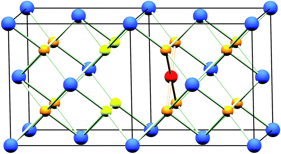 | ||
| Fig. 1 The CeO2 structure (two unit cells shown) with one Ce4+ ion substituted for by a Pd2+ ion. Pd2+ is shown in red, Ce4+ in dark blue and O2− in orange. The resulting under-coordinated O2− sites are shown in yellow. This under-coordinated site is 75% occupied to achieve charge-balance. | ||
Results and discussion
Structure and solubility limit
Powder XRD patterns of Ce1−xPdxO2−δ (Fig. 2a) show a single nanocrystalline fluorite phase is present in each case up to x = 0.25. When x ≥ 0.30, Bragg peaks attributed to crystalline PdO were seen in the diffraction pattern. Whilst there is no indication of PdO in Ce0.75Pd0.25O2−δ in the diffraction data, the lattice parameter is almost identical to that of Ce0.80Pd0.20O2−δ, suggesting that no more Pd has been substituted into the lattice by this point. In fact a linear lattice expansion can be seen only up to x = 0.15 (Fig. 2b), suggesting the upper limit of Pd inclusion is actually between 0.15 and 0.20 (the EXAFS analysis described below clarifies this point). Other Pd-containing ceria samples reported in the literature have also been shown to exhibit lattice expansion with increasing Pd content: for example, Kurnatowska et al. produced materials by a water-in-oil microemulsion method followed by calcination in air at 500 °C and found a similar lattice expansion with homogeneous materials up to x = 0.20,22 while Misch et al. produced materials with up to 10 mol% Pd substitution by ultrasonic spray pyrolysis at 500 °C, and also found a lattice parameter expansion,21 although somewhat smaller than seen for our materials. Materials prepared by ultrasonication also show a maximum value of x of 0.10,20 and the lattice parameters reported are comparable to that of Misch et al. (see ESI Fig. S1† for a comparison between our materials and these literature values). Other published papers on Pd doping of ceria use much lower Pd content and lattice parameters are very similar to that of undoped CeO2,18,27 or are co-doped with other metals.25,28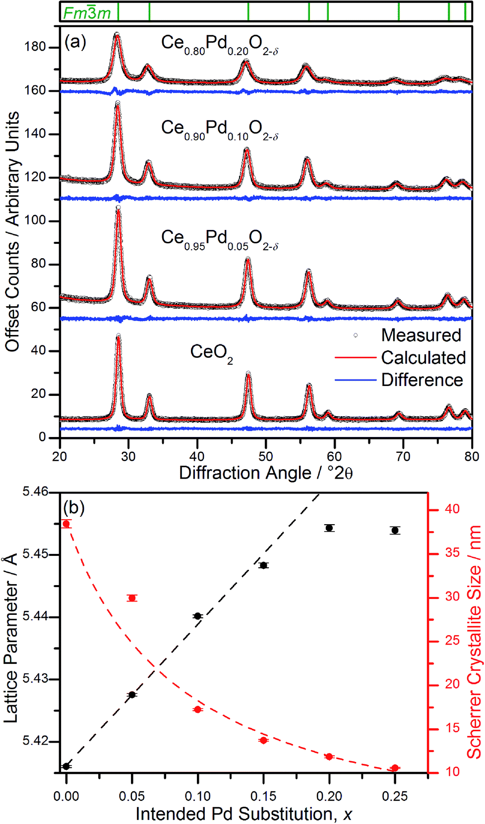 | ||
Fig. 2 (a) Fits to powder XRD data (λ = 1.54056 Å) of Ce1−xPdxO2−δ (x = 0, 0.05, 0.10, 0.20). Tick marks above denote positions of fluorite cell, space group Fm![[3 with combining macron]](https://www.rsc.org/images/entities/char_0033_0304.gif) m. (b) Refined lattice parameter, a, and crystallite size as a function of intended Pd substitution, x. In (b) the linear fit of lattice parameters is over the range 0 ≤ x ≤ 0.15 (see text for discussion) and the curved line is a guide to the eye. m. (b) Refined lattice parameter, a, and crystallite size as a function of intended Pd substitution, x. In (b) the linear fit of lattice parameters is over the range 0 ≤ x ≤ 0.15 (see text for discussion) and the curved line is a guide to the eye. | ||
The ionic radius of Pd2+ is significantly smaller (0.64–0.86 Å depending on geometry29) than eight-coordinate Ce4+ (0.97 Å (ref. 29)), and a lattice contraction would thus be expected if Pd were simply occupying the Ce 4a crystallographic site in the fluorite structure. The lattice expansion observed is, however, consistent with the Pd2+ ion residing in a square-planar site at the centre of one of the faces belonging to the CeO8 cubes, Fig. 1. An unexpanded fluorite CeO2 unit cell would give Pd–O distances of ∼1.91 Å in this arrangement, significantly shorter than has been found in other square-planar Pd oxides; such as PdO30 and La2Pd2O5 and La4PdO7,31 all of which have Pd–O bond lengths of 2.01–2.07 Å. Thus the presence of Pd2+ in this environment would be expected to cause an expansion of the ceria lattice to accommodate the Pd2+ ion and give physically reasonable Pd–O bond lengths. The powder XRD also shows that there is significant broadening of the Bragg peaks as x is increased, suggesting that the crystallite size is decreasing. This effect has also been seen with other dopants in CeO2.32 It is also possible that strain associated with the distorted metal environment is a factor in peak broadening. Rietveld analysis of the structure is complicated by the broad diffraction profile and the likely high thermal parameters of oxygen, but using a model based on Fig. 1 the refined oxygen content is consistent with increasing oxide deficiency with increased Pd content and the general chemical formula Ce1−xPdxO2−δ (see ESI†).
Elemental analysis showed that the Ce![[thin space (1/6-em)]](https://www.rsc.org/images/entities/char_2009.gif) :Pd ratio in the as-made oxides is the same as expected in the reaction mixtures (ESI, Table S1†). High resolution transmission electron microscopy of hydrothermally prepared CeO2, Ce0.90Pd0.10O2−δ and Ce0.80Pd0.20O2−δ (Fig. 3) shows that the particle size decreases as x increases from around 10–20 nm of CeO2 to sub-10 nm particles of Ce0.80Pd0.20O2−δ. Energy-dispersive X-ray spectroscopy (EDX) elemental analysis of Ce0.90Pd0.10O2−δ and Ce0.80Pd0.20O2−δ at multiple points found that the Ce:Pd ratio is both consistent with the intended values and the metals are homogeneously distributed throughout the oxides (ESI, Table S2†). Ce LIII-edge XANES spectra of all the samples (ESI, Fig. S3†) shows that the average Ce oxidation state and local environment remains as in CeO2. While the presence of Ce(III) could also lead to lattice expansion, and indeed in small particles of CeO2 some reduction of the cerium is often found,33 for our materials there is no evolution of the XANES signal with Pd doping, so the increased Pd content must be largely be responsible for the lattice expansion. The Pd K-edge XANES suggests that the Pd is found primarily in the +2 oxidation state, although there is possible evidence for some local oxide deficiency giving partially oxidised Pd, since the local structure is not identical to as seen in PdO (ESI, Fig. S4†).
:Pd ratio in the as-made oxides is the same as expected in the reaction mixtures (ESI, Table S1†). High resolution transmission electron microscopy of hydrothermally prepared CeO2, Ce0.90Pd0.10O2−δ and Ce0.80Pd0.20O2−δ (Fig. 3) shows that the particle size decreases as x increases from around 10–20 nm of CeO2 to sub-10 nm particles of Ce0.80Pd0.20O2−δ. Energy-dispersive X-ray spectroscopy (EDX) elemental analysis of Ce0.90Pd0.10O2−δ and Ce0.80Pd0.20O2−δ at multiple points found that the Ce:Pd ratio is both consistent with the intended values and the metals are homogeneously distributed throughout the oxides (ESI, Table S2†). Ce LIII-edge XANES spectra of all the samples (ESI, Fig. S3†) shows that the average Ce oxidation state and local environment remains as in CeO2. While the presence of Ce(III) could also lead to lattice expansion, and indeed in small particles of CeO2 some reduction of the cerium is often found,33 for our materials there is no evolution of the XANES signal with Pd doping, so the increased Pd content must be largely be responsible for the lattice expansion. The Pd K-edge XANES suggests that the Pd is found primarily in the +2 oxidation state, although there is possible evidence for some local oxide deficiency giving partially oxidised Pd, since the local structure is not identical to as seen in PdO (ESI, Fig. S4†).
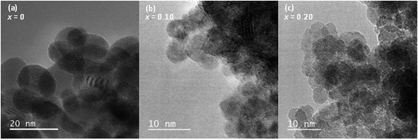 | ||
| Fig. 3 HR-TEM micrographs of (a) CeO2, (b) Ce0.90Pd0.10O2−δ and (c) Ce0.80Pd0.20O2−δ. | ||
EXAFS analysis of local structure of Pd
Pd K-edge EXAFS spectra of Ce1−xPdxO2−δ (x = 0.05, 0.10, 0.20) show a marked difference to the spectrum of PdO (Fig. 4). The calculated χ(k) of PdO based on its crystal structure with distances and thermal parameters allowed to refine, fits closely the measured data (Fig. 4a, and Table 1), and this same model yields a poor fit to the Pd-substituted ceria fluorites with incorrect refined correlation distances and unphysical thermal parameters, eliminating the possibility of Pd existing solely as amorphous PdO in the ceria materials. We note here that previous EXAFS studies of Pd-doped ceria materials by Hegde and co-workers, erroneously assigned an O–O distance of 2.67 Å in PdO as due to Pd–Pd and used this in their EXAFS modelling,18,34 so we are unsure as to the validity of their fitted parameters in the lightly doped samples they prepared by solution combustion. Instead we have used the structural model shown in Fig. 1 to describe the local structure, where Pd is substituted into ceria, but rather than occupying the Ce site it is shifted to sit at the centre of a plane of four equidistant O atoms. An initial model with no expansion of the unit cell was used (i.e. with Pd–O distances of 1.9 Å) and on refinement of structural parameters against the Pd K-edge EXAFS spectra of Ce0.95Pd0.05O2−δ, Ce0.90Pd0.10O2−δ and Ce0.80Pd0.20O2−δ (Fig. 4) increased correlation distances compared to the unexpanded model were produced, (Table 1) in accordance with the lattice expansion seen by powder XRD data, Fig. 2a. Ce0.95Pd0.05O2−δ and Ce0.90Pd0.10O2−δ can be well fitted by three shells of atoms and adding subsequent shells gave no improvement on the fit and caused the closer shells to have physically unreasonable values, suggesting a degree of disorder on this length scale. The fit to Ce0.95Pd0.05O2−δ has a comparatively large R-factor due to the reduced signal-to-noise ratio, particularly evident at high k, in this dilute sample.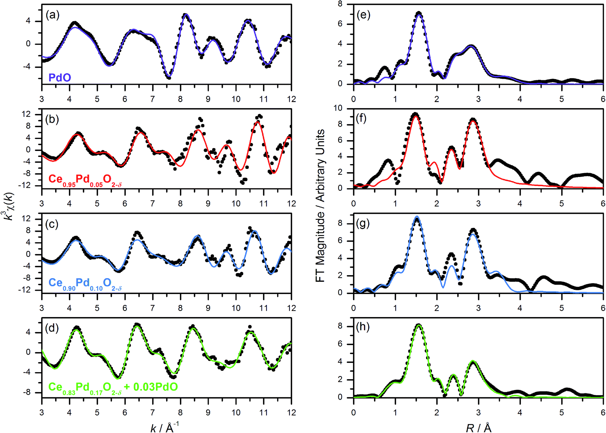 | ||
| Fig. 4 (a–d) Pd K-edge k3-weighted EXAFS spectra (points) with fits (lines); and (e–h) Fourier transforms of PdO, Ce0.95Pd0.05O2−δ, Ce0.90Pd0.10O2−δ and Ce0.80Pd0.20O2−δ (nominal composition), respectively. | ||
| Compound (fit parameters) | Shell | Coordination number | R cryst/Å | R/Å | σ 2/Å2 |
|---|---|---|---|---|---|
| PdO (S02 = 0.826, E0 = 1.052 eV, R-factor = 0.0312) | O | 4 | 2.018 | 2.035(10) | 0.002(1) |
| Pd | 4 | 3.030 | 3.055(12) | 0.008(1) | |
| Pd | 8 | 3.420 | 3.482(48) | 0.016(5) | |
| O | 8 | 3.640 | 3.888(80) | 0.010(12) | |
| O | 4 | 4.275 | 4.319(82) | 0.004(8) | |
| Pd | 4 | 4.285 | 4.285(257) | 0.023(40) | |
| Ce0.95Pd0.05O2−δ, (S02 = 0.909, E0 = −7.56 eV, R-factor = 0.179) | O | 4 | 1.910 | 1.963(26) | 0.0022(37) |
| Ce | 4 | 3.030 | 3.158(30) | 0.0034(27) | |
| O | 7 | 3.310 | 3.305(114) | 0.0045(16) | |
| Ce0.90Pd0.10O2−δ, (S02 = 0.829, E0 = −7.836 eV, R-factor = 0.0876) | O | 4 | 1.910 | 1.983(14) | 0.0017(19) |
| Ce | 4 | 3.030 | 3.191(38) | 0.0044(21) | |
| O | 7 | 3.310 | 3.352(58) | 0.0011(80) | |
| Ce0.83Pd0.17O2−δ + 0.03PdO, (S02 = 0.826, E0 = −0.617 eV, R-factor = 0.0295) | O (fluorite and PdO) | 4 | 1.910 | 2.018(9) | 0.0019(6) |
| Pd (PdO) | 0.6 | 3.030 | 3.130(78) | 0.0003(22) | |
| Ce (fluorite) | 3.4 | 3.030 | 3.192(44) | 0.0044 | |
| O (fluorite) | 5.95 | 3.310 | 3.554(45) | 0.0010 | |
| Pd (PdO) | 1.2 | 3.420 | 3.503(47) | 0.0042(66) |
The Pd K-edge EXAFS signal of Ce0.80Pd0.20O2−δ cannot be satisfactorily fitted solely by the same model, however. Since powder XRD of Ce0.70Pd0.30O2−δ shows the presence of nanocrystalline PdO as a secondary phase; and between 0.15 ≤ x ≤ 0.25 the lattice parameter no longer increases linearly as a function of x (Fig. 2b), it is conceivable that a small amount of PdO, undetectable by powder XRD, is present as a second phase at x = 0.20. A two-phase model is difficult to fit to the EXAFS signal, however, since the Pd–Pd distance in PdO and the Pd–Ce distance in the doped model are both close to 3 Å. Therefore, some parameters had to be fixed in order to obtain a satisfactory fit: S02 was fixed at 0.826, the value found for PdO (and very close to the value for the doped model), and the Debye–Waller factor for the Ce shell was fixed at 0.0044 Å2 (found for the doped model) and the value for the second O shell at 0.001 Å2. The proportion of Pd present as PdO was estimated by fitting the lattice parameter of the fluorite to the extrapolated linear fit (fitted over the region 0 ≤ x ≤ 0.15) to give value of x = 0.17. This means that approximately 15% of the Pd is present as PdO and 85% is found in Ce0.83Pd0.17O2−δ. Fitting this model to the EXAFS spectrum gives a good fit (R-factor = 0.0295, Table 1). The addition PdO in this material must be of too small a crystal size to be resolved in the powder XRD. This is then consistent with the maximum amount of Pd in Ce1−xPdxO2−δ being x = 0.15 from our hydrothermal synthesis method.
Thermal stability and redox properties
In situ powder diffraction on heating in air of Ce1−xPdxO2−δ (x = 0.05, 0.10) shows the materials are stable up to at least 800 °C (Fig. 5), with no trace of Pd or PdO observed. However, although Ce0.85Pd0.15O2−δ was observed to have only fluorite reflections at 750 °C, at 800 °C Pd metal peaks are also present, suggesting that at high Pd-content the oxide is less stable (Fig. 5).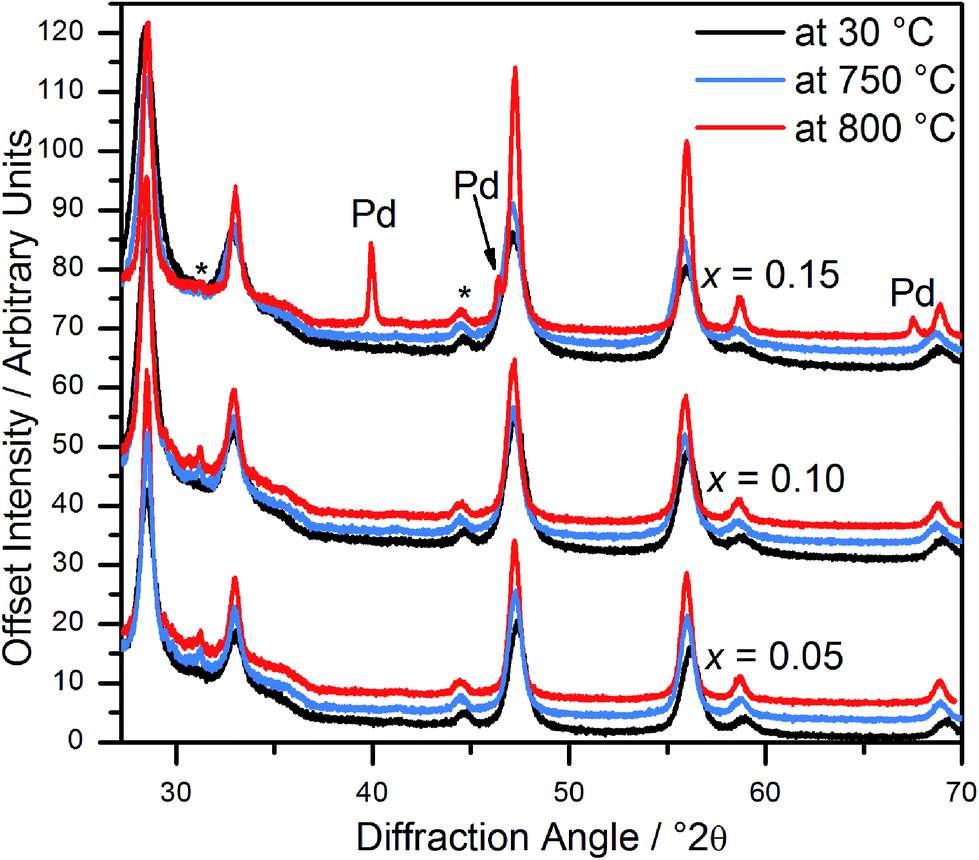 | ||
| Fig. 5 In situ powder XRD patterns of Ce1−xPdxO2−δ (x = 0.05, 0.10 and 0.15) at 30 °C, 750 °C and 800 °C. Asterisks denote the position of peaks attributed to the sample holder. | ||
H2-TPR profiles of Ce1−xPdxO2−δ (0 ≤ x ≤ 0.25) up to 250 °C (Fig. 6a) show in each case the presence of a large, sharp, low temperature reduction peak, which cannot be solely attributed to the reduction of Pd2+ to Pd metal on the basis of quantification of the amount of hydrogen consumed. The temperature of the maximum hydrogen uptake decreases as x increases, and the total amount of hydrogen oxidised tends to increase linearly with increasing x up to x = 0.20 (Fig. 6b). The TPR profile of hydrothermally prepared CeO2 over the same range (not shown) showed no visible hydrogen oxidation. The increasing hydrogen oxidation in the Pd-containing materials cannot be solely attributed to the increasing amount of Pd2+ present being reduced: a significant, increasing proportion of Ce4+ reduction must be occurring (up to x = 0.20). Assuming complete reduction of the Pd, then the percentage of cerium that is reduced can be calculated: this is plotted in Fig. 6b and the results shown in Table S3 of the ESI.† When x ≥ 0.20 the reduction peak begins to split into two peaks, possibly due to the presence of a PdO impurity (as observed in the EXAFS analysis). The increasing proportion of Ce4+ reduction (up to x = 0.20) suggests that the presence of ionic Pd2+ distributed throughout the structure leads to greater reducibility of the Ce4+. The origin of the enhanced reducibility of the materials can thus be ascribed to be due to a combination of the expansion of the lattice and the higher level of oxide defects as more Ce4+ is substituted by Pd2+, both of which can be envisaged to enhance oxide-ion migration, in turn leading to more easy removal of oxygen with increased Pd content. Since the analysis above showed that further addition of Pd (i.e. intended x = 0.25) leads to the formation of amorphous PdO in an inhomogeneous mixture this explains the fact that this material has a lower than expected hydrogen uptake.
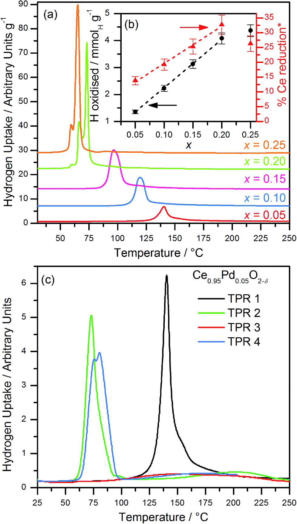 | ||
| Fig. 6 (a) H2-TPR profiles of Ce1−xPdxO2−δ (0.05 ≤ x ≤ 0.25, nominal compositions) from ambient temperature to 250 °C. (b) H oxidised per gram of sample and corresponding %Ce reduction as a function of x (* %Ce reduction, assuming complete Pd2+ reduction), with linear fit over range 0.05 ≤ x ≤ 0.20. Error bars ±5%. (c) Cycled TPR experiments: TPR1 was performed on a freshly made sample, TPR2 after reoxidation at 700 °C, TPR3 after reoxidation at 500 °C and TPR4 after reoxidation to 700 °C. | ||
For the lowest concentration of Pd (5 mol%), the effect of recycling the TPR experiment was investigated, Fig. 6c. This shows that after re-oxidation to 700 °C the hydrogen reduction occurs at markedly lower temperature (∼75 °C). This is reproducible (see TPR4 on Fig. 6c) but re-oxidation at the lower temperature of 500 °C is not sufficient to regenerate the low temperature reduction (TPR3). The material thus formed after the first TPR-TPO cycle resembles Pd dispersed on CeO2: for example Luo et al. studied ceria onto which Pd had been added by wet impregnation and found the same sharp single reduction peak at 75 °C in the TPR.35 The TPR trace of our Ce0.95Pd0.05O1.95 material after a cycle of reduction–oxidation (TPR2 on Fig. 6c) is remarkably similar to that reported for Luo et al. for 2% and 5% Pd loaded on ceria. This would be consistent with the extrusion of Pd from the Pd-doped CeO2 in the first TPR cycle in our materials to give surface Pd, suggesting an inherent instability of Pd when incorporated into the ceria lattice.
TEM before and after heat treatment, Fig. 7, confirms that Pd metal is easily released from the materials. The EELS maps clearly show how Pd is evenly dispersed in the same region as cerium in the as-made materials (Ce0.95Pd0.05O2−δ in this case), but after heating in air the Pd is phase separated and agglomerates in separate particles, >10 nm in dimension. This would explain the results of TPR-TPO cycling where after reoxidising in air to 700 °C the materials resemble Pd dispersed on a CeO2 support.
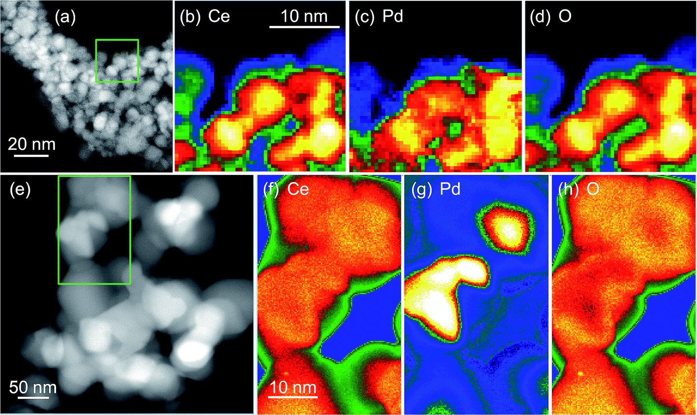 | ||
| Fig. 7 HAADF images of crystallites in 5 mol% Pd–CeO2 (a) before and (e) after heating oxidation in air at 800 °C and Ce M4,5, Pd M4,5 and O K EELS maps (b–d) before and (f–h) after oxidation. The green boxes in (a) and (e) show the areas selected for the EELS maps. | ||
Experimental
Samples of Ce1−xPdxO2−δ (nominally 0 ≤ x ≤ 0.25 in increments of x = 0.05) were prepared by hydrothermal reactions at 240 °C. CeCl3·7H2O (Aldrich, 99.9%) and PdCl2 (Johnson Matthey, 99.8%) were mixed in a (1 − x):x molar ratio; respectively; to give a total of 6 mmol of metal ions. To this 2 ml cold H2O was added, yielding a solution, to which 2 ml of H2O2 (Aldrich, 30% aqueous solution) was added. This mixture was stirred for 15 minutes before 8 ml of 7.5 M NaOH was added dropwise with effervescence. The red-brown gel was stirred for a further 10–15 minutes before being sealed in a Teflon-lined steel autoclave and placed in a pre-heated fan oven to 240 °C for 24 hours. The autoclave was cooled to room temperature before filtration and washing with copious amounts of boiling water. The resulting brown solids were dried in an oven at 80 °C overnight and ground in a pestle and mortar to give fine powders.
Powder X-ray diffraction (XRD) patterns for phase identification were measured using a Siemens D5000 diffractometer operating with Cu Kα1/2 radiation. High resolution powder XRD data were collected using a Panalytical X'Pert Pro MPD diffractometer with monochromatic Cu Kα1 radiation and a PIXcel solid-state detector. Non-ambient powder XRD measurements were made using a Bruker D8 Advance diffractometer with Cu Kα1/2 radiation and fitted with a VÅNTEC-1 high-speed detector. Powders were heated in situ using an Anton Paar XRK 900 reaction chamber controlled either in static air or under a flow of 5% hydrogen in nitrogen. Powder XRD patterns were fitted using a Le Bail profile refinement with the GSAS software,36 which allowed refinement of lattice parameters and peak broadening parameters.
Thermogravimetric analysis (TGA) was performed using a Mettler Toledo Systems TGA/DSC 1 instrument under an air flow of 50 ml min−1 from room temperature to 1000 °C at a heating rate of 10 °C min−1.
Inductively coupled plasma optical emission spectroscopy (ICP-OES) was used to determine the amounts of the metals present in the samples by the company MEDAC Ltd (UK).
XANES and EXAFS spectra were measured using B18 at Diamond Light Source.37 Data were collected in transmission mode at the Ce LIII-edge and the Pd K-edge from samples diluted with appropriate amounts of polyethylene powder and pressed in self-supporting discs around 1 mm thick. The incident energy was selected using a water-cooled, fixed-exit, double-crystal monochromator with Si (311) crystals. On B18 a double toroidal mirror, coated with Cr and Pt, 25 m from the source is used to focus the beam horizontally and vertically onto the sample and a pair of smaller plane mirrors are used for harmonic rejection. The raw data were treated using the programme Athena38 to produce XANES spectra, normalised to the post-edge background, and normalised EXAFS spectra. The Pd K-edge EXAFS spectra were analysed using the software Artemis,38 which implements the FEFF code, over the k-range 3–12 Å−1. For the crystalline reference material PdO the coordination numbers were set at values expected from the known structure and shell distances (R) and thermal parameters (σ2) along with threshold energy (E0) and amplitude reduction factor (S02) were allowed to vary in least-squares refinements to obtain a satisfactory fit to the k3-weighted EXAFS. For the Pd-containing ceria samples, various structural models were considered, as described below, and the goodness of fit assessed, while it was checked that the refined amplitude reduction factor (S02) gave a value similar to that obtained for PdO.
High resolution transmission electron microscopy (TEM) and electron energy loss spectrum imaging (EELS-SI) studies were performed on a probe-corrected JEOL ARM 200F microscope operating at 200 kV and equipped with a Gatan GIF Quantum ER spectrometer. High angle annular dark field (HAADF) images were produced and for EELS-SI a dispersion of 0.5 eV per channel was set and spectra with 2048 channels were recorded with an energy range of 1024 eV in each spectrum. The Gatan spectrum imaging plugin was used for EELS-SI acquisitions. This yielded 3D data sets with each pixel containing an individual EELS spectrum. Elemental maps of Pd M4,5-edge, O K-edge, and Ce M4,5-edge were produced after a suitable pre-edge inverse power law background fitting with energy windows of 30 eV, 35 eV, and 45 eV respectively. Temperature programmed reduction (TPR) was measured by thermal conductivity of the 10% H2 in N2 (at a flow rate of 30 ml min−1) before and after contact with the 0.05–0.10 g sample. A H2O trap after the sample was used to absorb water created by H2 oxidation. Temperature was increased linearly as a function of time. In order to quantify accurately the hydrogen consumption a known quantity (1 ml) of N2 was injected into the H2/N2 gas stream before the experiment began to create a calibration peak. Quantification of H2 consumption was carried by the integration of TPR profile as a function of time. Results are presented as the amount of H atoms oxidised per gram of sample, mmol (H) g−1. The error is estimated to be ±5% for the total H2 consumption in these measurements. Temperature programme oxidation (TPO) in the same apparatus was performed with 10% O2 in He at the same flow rate to examine recyclability of the materials.
Conclusions
In conclusion, a series of nanocrystalline Pd-substituted ceria-type fluorites of the form Ce1−xPdxO2−δ (0.05 ≤ x ≤ 0.15) have been prepared by low-temperature hydrothermal synthesis. Attempts to achieve a higher value of Pd substitution led to the formation of PdO as a secondary phase. Analysis of the Pd K-edge EXAFS and the powder XRD have been used to infer a square-planar coordination, brought about by Pd offset from the Ce sites within the fluorite structure and also giving under-coordinated oxide ions and oxide vacancies. This supports a previously proposed model from computer simulation. The oxides have been demonstrated by in situ powder XRD to be stable in air up to at least 750–800 °C, but that Pd is extruded from the materials on heating beyond this. H2-TPR shows that increasing the Pd substitution leads to improved low-temperature reducibility of the oxides, but that on cycling the materials resemble Pd dispersed on ceria, consistent with an inherent instability of Pd2+ within the ceria lattice. Despite this, the material formed has a reduction profile that resembles Pd dispersed onto pre-made ceria by we impregnation, and so a material with potential use in catalysis is formed. Further work would be required to understand the structural distortions introduced by Pd2+ in ceria, such as by pair distribution function analysis, and also it would be informative to perform an in operando spectroscopic study to analyse the migration of Pd from the lattice to the surface of ceria, as this would allow the mechanism of redox chemistry to be understood.Acknowledgements
We thank Johnson Matthey plc for the provision of a CASE studentship for C.I.H. Some of the equipment used in materials characterisation at the University of Warwick was obtained through the Science City Advanced Materials project “Creating and Characterising Next Generation Advanced Materials” with support from Advantage West Midlands (AWM) and part funded by the European Regional Development Fund (ERDF). We are grateful to Diamond Light Source Ltd for provision of beamtime and we thank Dr G. Cibin for his help in recording data on B18.References
- H. Kušar, S. Hočevar and J. Levec, Appl. Catal., B, 2006, 63, 194 CrossRef PubMed; A. Trovarelli and P. Fornasiero, Catalysis by Ceria and Related Materials, Imperial College Press, London, 2nd edn, 2013 Search PubMed.
- A. Trovarelli, Catal. Rev.: Sci. Eng., 1996, 38, 439 CAS.
- F. Giordano, A. Trovarelli, C. de Leitenburg and M. Giona, J. Catal., 2000, 193, 273 CrossRef CAS.
- P. Fornasiero, R. Di Monte, G. R. Rao, J. Kašpar, S. Meriani, A. Trovarelli and M. Graziani, J. Catal., 1995, 151, 168 CrossRef CAS; D. Martin and D. Duprez, J. Phys. Chem., 1996, 100, 9429 CrossRef; Y. Liu, T. Hayakawa, T. Ishii, M. Kumagai, H. Yasuda, K. Suzuki, S. Hamakawa and K. Murata, Appl. Catal., A, 2001, 210, 301 CrossRef; N. Barrabés, K. Föttinger, A. Dafinov, F. Medina, G. Rupprechter, J. Llorca and J. E. Sueiras, Appl. Catal., B, 2009, 87, 84 CrossRef PubMed.
- J. Kašpar, P. Fornasiero and M. Graziani, Catal. Today, 1999, 50, 285 CrossRef CAS; R. Di Monte and J. Kašpar, Top. Catal., 2004, 28, 47 CrossRef.
- R. J. Gorte, AIChE J., 2010, 56, 1126 CAS.
- S. Hilaire, X. Wang, T. Luo, R. J. Gorte and J. Wagner, Appl. Catal., A, 2001, 215, 271 CrossRef CAS.
- A. T. Bell, Science, 2003, 299, 1688 CrossRef CAS PubMed; P. Fornasiero, G. Balducci, J. Kašpar, S. Meriani, R. Di Monte and M. Graziani, Catal. Today, 1996, 29, 47 CrossRef.
- R. Di Monte and J. Kašpar, J. Mater. Chem., 2005, 15, 633 RSC.
- M. Cargnello, J. J. Delgado Jaen, J. C. Hernandez Garrido, K. Bakhmutsky, T. Montini, J. J. Calvino Gamez, R. J. Gorte and P. Fornasiero, Science, 2012, 337, 713 CrossRef CAS PubMed; S. Colussi, A. Gayen, M. F. Camellone, M. Boaro, J. Llorca, S. Fabris and A. Trovarelli, Angew. Chem., Int. Ed., 2009, 48, 8481 CrossRef PubMed.
- G. Ranga Rao and B. G. Mishra, Bull. Catal. Soc., 2003, 2, 122 Search PubMed.
- J. A. Kurzman, L. M. Misch and R. Seshadri, Dalton Trans., 2013, 14653 RSC.
- T. Baidya, A. Gayen, M. S. Hegde, N. Ravishankar and L. Dupont, J. Phys. Chem. B, 2006, 110, 5262 CrossRef CAS PubMed; T. Baidya, M. S. Hegde and J. Gopalakrishnan, J. Phys. Chem. B, 2007, 111, 5149 CrossRef PubMed.
- W. Huang, P. Shuk and M. Greenblatt, Chem. Mater., 1997, 9, 2240 CrossRef CAS; H. L. Tuller and A. S. Nowick, J. Electrochem. Soc., 1975, 122, 255 CrossRef PubMed; B. C. H. Steele, Solid State Ionics, 2000, 129, 95 CrossRef.
- G. B. Balazs and R. S. Glass, Solid State Ionics, 1995, 76, 155 CrossRef.
- M. S. Hegde, G. Madras and K. C. Patil, Acc. Chem. Res., 2009, 42, 704 CrossRef CAS PubMed.
- A. Gayen, K. R. Priolkar, P. R. Sarode, V. Jayaram, M. S. Hegde, G. N. Subbanna and S. Emura, Chem. Mater., 2004, 16, 2317 CrossRef CAS; A. R. Derk, G. M. Moore, S. Sharma, E. W. McFarland and H. Metiu, Top. Catal., 2014, 57, 118 CrossRef PubMed.
- K. R. Priolkar, P. Bera, P. R. Sarode, M. S. Hegde, S. Emura, R. Kumashiro and N. P. Lalla, Chem. Mater., 2002, 14, 2120 CrossRef CAS.
- P. Bera, K. C. Patil, V. Jayaram, G. N. Subbanna and M. S. Hegde, J. Catal., 2000, 196, 293 CrossRef CAS.
- P. Singh and M. S. Hegde, Cryst. Growth Des., 2010, 10, 2995 CAS.
- L. M. Misch, J. A. Kurzman, A. R. Derk, Y.-I. Kim, R. Seshadri, H. Metiu, E. W. McFarland and G. D. Stucky, Chem. Mater., 2011, 23, 5432 CrossRef CAS.
- M. Kurnatowska, L. Kepinski and W. Mista, Appl. Catal., B, 2012, 117–118, 135 CrossRef CAS PubMed.
- P. Singh and M. S. Hegde, Chem. Mater., 2009, 21, 3337 CrossRef CAS.
- R. I. Walton, Prog. Cryst. Growth Charact. Mater., 2011, 57, 93 CrossRef CAS PubMed.
- R. Mistri, J. Llorca, B. C. Ray and A. Gayen, J. Mol. Catal. A: Chem., 2013, 376, 111 CrossRef CAS PubMed.
- D. O. Scanlon, B. J. Morgan and G. W. Watson, Phys. Chem. Chem. Phys., 2011, 13, 4279 RSC.
- T. Baidya, G. Dutta, M. S. Hegde and U. V. Waghmare, Dalton Trans., 2009, 3, 455 RSC; S. Sharma, Z. Hu, P. Zhang, E. W. McFarland and H. Metiu, J. Catal., 2011, 278, 297 CrossRef CAS PubMed; L. Meng, A.-P. Jia, J.-Q. Lu, L.-F. Luo, W.-X. Huang and M.-F. Luo, J. Phys. Chem. C, 2011, 115, 19789 Search PubMed.
- A. Gupta, M. S. Hegde, K. R. Priolkar, U. V. Waghmare, P. R. Sarode and S. Emura, Chem. Mater., 2009, 21, 5836 CrossRef CAS; A. Gupta, A. Kumar, U. V. Waghmare and M. S. Hegde, Chem. Mater., 2009, 21, 4880 CrossRef.
- R. D. Shannon, Acta Crystallogr., Sect. A: Cryst. Phys., Diffr., Theor. Gen. Crystallogr., 1976, 32, 751 CrossRef.
- J. Waser, H. A. Levy and S. W. Peterson, Acta Crystallogr., Sect. A: Cryst. Phys., Diffr., Theor. Gen. Crystallogr., 1953, 6, 661 CrossRef CAS.
- J. P. Attfield, Acta Crystallogr., Sect. B: Struct. Sci., 1988, 44, 563 CrossRef.
- K. Sardar, H. Y. Playford, R. J. Darton, E. R. Barney, A. C. Hannon, D. Tompsett, J. Fisher, R. J. Kashtiban, J. Sloan, S. Ramos, G. Cibin and R. I. Walton, Chem. Mater., 2010, 22, 6191 CrossRef CAS; G. Li, R. L. Smith and H. Inomata, J. Am. Chem. Soc., 2001, 123, 11091 CrossRef.
- P. Nachimuthu, W. C. Shih, R. S. Liu, L. Y. Jang and J. M. Chen, J. Solid State Chem., 2000, 149, 408 CrossRef CAS.
- T. Baidya, K. R. Priolkar, P. R. Sarode, M. S. Hegde, K. Asakura, G. Tateno and Y. Koike, J. Chem. Phys., 2008, 128, 124711 CrossRef PubMed.
- M. F. Luo, Z. Y. Hou, X. X. Yuan and X. M. Zheng, Catal. Lett., 1998, 50, 205 CrossRef CAS.
- A. C. Larson and R. B. Van Dreele, Los Alamos National Laboratory Report LAUR, 1994, 86.
- A. J. Dent, G. Cibin, S. Ramos, A. D. Smith, S. M. Scott, L. Varandas, M. R. Pearson, N. A. Krumpa, C. P. Jones and P. E. Robbins, J. Phys.: Conf. Ser., 2009, 190, 012039 CrossRef.
- B. Ravel and M. Newville, J. Synchrotron Radiat., 2005, 12, 537 CrossRef CAS PubMed.
Footnote |
| † Electronic supplementary information (ESI) available. See DOI: 10.1039/c5ta02007g |
| This journal is © The Royal Society of Chemistry 2015 |