Synthesis of sodium manganese oxides with tailored multi-morphologies and their application in lithium/sodium ion batteries
Maowen Xu†
*ab,
Yubin Niu†ab,
Yutao Lic,
Shujuan Baoab and
Chang Ming Liab
aInstitute for Clean Energy & Advanced Materials, Faculty of Materials and Energy, Southwest University, Chongqing 400715, P. R. China. E-mail: xumaowen@swu.edu.cn; Fax: +86-23-68254969; Tel: +86-23-68254969
bChongqing Key Laboratory for Advanced Materials and Technologies of Clean Energies, Chongqing 400715, P. R. China
cTexas Materials Institute, University of Texas Austin, Texas 78712, USA
First published on 30th June 2014
Abstract
Sodium manganese oxides (SMO) with different crystal structures have been synthesized by high-temperature solid-state reaction (HTSSR), in which both morphology and crystal structure of SMO can be well-controlled by synergistic effects of both the ratio of sodium-to-manganese and the heat-treatment temperature. The material is further used as the cathode in Li/Na-ion batteries, and the experimental results indicated that the performance of SMO as the electrode material mainly depends on its crystal structure, while its morphology only plays an important role in the initial stage. SMO with a 3-D tunnel structure (Na0.44MnO2) and a layer structure (Na0.67MnO2 and Na0.91MnO2) delivers better battery performance.
1. Introduction
Manganese oxides have generated a great deal of interest as one kind of cathode material for rechargeable lithium batteries due to their high specific energy, low cost, low toxicity and safety. Many studies have been performed on the synthesis and characterization of kinds of electrochemically active manganese oxides based on the Li–Mn–O system.1–7 However, some problems are still standing in the utilisation of lithium manganese oxides as cathode in the practical Li-ion batteries, such as Jahn–Teller lattice distortion, slow dissolution of manganese oxides and so on.8To overcome these problems, other kinds of electrochemically active manganese oxides based on Na–Mn–O system9–12 have drawn significant attention in recent years, which has a variety of crystal structures, such as P2 and O3 structure. Up to present, many researchers have made us aware of the conclusion that depending on the sodium contents and reaction temperature, either tunnel compounds13 or layered compounds14 can be obtained during synthesis in the Na–Mn–O system. They are often used as sodium-ion battery materials; however, all of these materials undergo at least one or more phase transformations leading to several voltage steps in their electrochemical profiles. These transformations represent major practical issues for Na-ion batteries because they greatly shorten cycle life and reduce rate capabilities and energy density.15 Therefore, some authors used these phases as precursor for the synthesis of lithiated layered manganese oxides via an ion-exchange procedure.16,17 As the electrode material of lithium ion battery, the contained Na ions as pillaring species between MnO2 layers has been proven to limit the magnitude of the structural response of the host lattice during the Li insertion extraction reaction.18 Although there are too many methods to synthesize sodium manganese oxides or other Na compounds (NaxMnyAz, A = transition metal), such as solid-state route,12,19 glycine–nitrate combustion,20 hydrothermal synthesis,21,22 thermo-chemical conversion,23 polymer-pyrolysis,24 coprecipitation technique15 and molten salt synthesis.25 To our knowledge, however, there is no systematically study about the influence of the precursor's morphologies, sodium-to-manganese molar ratio (R) and temperature on the Na–Mn–O system.
In this work, cathode materials NaxMnO2 were synthesized by high temperature solid state reaction (HTSSR), and their morphologies and crystal structures could be tailored by controlling the sintering temperature and R. SMO with 3-D tunnel structure (Na0.44MnO2) and layer structure (Na0.67MnO2 and Na0.91MnO2), which have better battery performance, could be obtained. The metal segregation phenomenon was verified as well.
2. Experimental section
All chemical reagents were analytical grade and were used as received.2.1 Synthesis
The synthesis of Mn2O3 rods, cubics and ovals were carried out on the basis of our previous work with minor modification.26 In a typical synthesis, 0.13 g KMnO4 and 0.026 g D-maltose were dissolved in 35 mL of distilled water under magnetic stirring. After 15 min stirring, the mixture was transferred and sealed in a 45 mL Teflon-lined autoclave, heated at 180 °C for 8 h, and then cooled to room temperature. The precipitates were collected by filtration, washed alternately with deionized water and ethanol three times, and dried in air at ambient conditions. Finally, the products were subjected to heat treatment in air at 600 °C for 5 h. Mn2O3 cubics and ovals were prepared by keeping other conditions unchanged and rising mass of KMnO4 to 0.35 g and 0.53 g and rising mass of D-maltose to 0.27 g and 0.8 g, respectively.Mn2O3 spheres were prepared in a procedure described by Li's group with amelioration.27 15 mL ethanol (AR) was added into 150 mL MnSO4 solution with the concentration of 0.0143 mol L−1 under stirring. 150 mL NH4HCO3 solution with concentration of 0.143 mol L−1 was directly put into the mixture solution mentioned above under vigorous stirring. The obtained suspension was maintained at room temperature for 12 h. Finally, the as-obtained precursors were subjected to the same process as described above.
NaxMnO2 was prepared from high-temperature solid-state reaction (HTSSR) by mixing thoroughly NaOH and the as-prepared various morphologies of Mn2O3 in distilled water with R of 0.45, 0.50, 0.70 and 1.05, respectively. After rotary evaporation, the resulting powders were then heated to 600 °C (500 °C, 650 °C and 800 °C) in air at a rate of 2 °C min−1 and held at 600 °C for 10 h followed by cooling. The samples with different morphologies, temperatures and R were obtained. The samples NaxMnO2 with rods, cubics, ovals and spheres were referred as R-SMO, C-SMO, O-SMO and S-SMO, respectively.
2.2 Material characterization
The crystal structures of the as-prepared SMO samples were characterized by powder X-ray diffraction (XRD, MAXima-X XRD-7000). The morphology and microstructure were examined by field-emission scanning electron microscopy (SEM, JSM-6700F).2.3 Electrochemical measurement
The electrodes were fabricated by using the as-prepared SMO as the active materials, conductive carbon blacks (Super-P) and polyvinylidenefluoride (PVdF) binder in a weight ratio of 80![[thin space (1/6-em)]](https://www.rsc.org/images/entities/char_2009.gif) :10:10. The slurry was coated on an aluminium foil and dried for 12 h in a vacuum oven at 120 °C. For lithium-ion battery, Li foil was used as the counter electrode and polypropylene (PP) film (Celgard 2400) as the separator. The electrolyte was 1 M LiPF6 in a mixture of ethylene carbonate (EC)–diethyl carbonate (DEC)–dimethyl carbonate (DMC) in a volume ratio of 1:1:1 with 5 wt% vinylenecarbonate (VC) as additive. For sodium-ion battery, a Na disk as counter electrode and 1 M NaClO4 in ethylene carbonate–diethyl carbonate (EC–DEC, 50:50 vol%) solution as electrolyte. The assembly of the cells was carried out in a dry Ar-filled glove box. The cells were galvanostatically charged and discharged between 2 V and 4.3 V versus Li/Li+ (or Na/Na+) on a battery cycler (LAND, CT2001A, China) at room temperature. Cyclic voltammogram (CV) was measured at a scan rate of 50 μV s−1 between 2.0 and 4.3 V using a CHI600D electrochemical analyzer. Electrochemical impedance spectroscopy experiments were conducted in the frequency range of 0.01–100 kHz with a CHI600D electrochemical analyzer.
:10:10. The slurry was coated on an aluminium foil and dried for 12 h in a vacuum oven at 120 °C. For lithium-ion battery, Li foil was used as the counter electrode and polypropylene (PP) film (Celgard 2400) as the separator. The electrolyte was 1 M LiPF6 in a mixture of ethylene carbonate (EC)–diethyl carbonate (DEC)–dimethyl carbonate (DMC) in a volume ratio of 1:1:1 with 5 wt% vinylenecarbonate (VC) as additive. For sodium-ion battery, a Na disk as counter electrode and 1 M NaClO4 in ethylene carbonate–diethyl carbonate (EC–DEC, 50:50 vol%) solution as electrolyte. The assembly of the cells was carried out in a dry Ar-filled glove box. The cells were galvanostatically charged and discharged between 2 V and 4.3 V versus Li/Li+ (or Na/Na+) on a battery cycler (LAND, CT2001A, China) at room temperature. Cyclic voltammogram (CV) was measured at a scan rate of 50 μV s−1 between 2.0 and 4.3 V using a CHI600D electrochemical analyzer. Electrochemical impedance spectroscopy experiments were conducted in the frequency range of 0.01–100 kHz with a CHI600D electrochemical analyzer.
3. Results and discussion
3.1 The effect of precursor morphology
X-ray diffraction (XRD) was carried out to determine the structures of the prepared samples. In the Na–Mn–O system, depending on the sodium contents and reaction temperatures, either tunnel or layered compounds can be obtained during synthesis. The former consists of columns of edge-sharing MnO5 square pyramids and sheets of edge-sharing MnO6 octahedra extending parallel to the c-axis (Fig. 1a).28 They are connected by corner-sharing to form two types of tunnels: large S-shaped, and six-sided tunnels, both occupied by Na+. However, the latter can be classified into two main groups according to earlier nomenclature: P2 or O3 phase (Fig. 1b), in which the sodium ions occupy the prismatic (P) and octahedral (O) sites, respectively. In general, O3-phase NaMnO2 is electrochemically active, but its reversible capacity struggles to exceed 120 mA h g−1. Compared with O3 phase, the P2-type phase may have much larger Na-ion storage capacity and worse cycling stability.11,29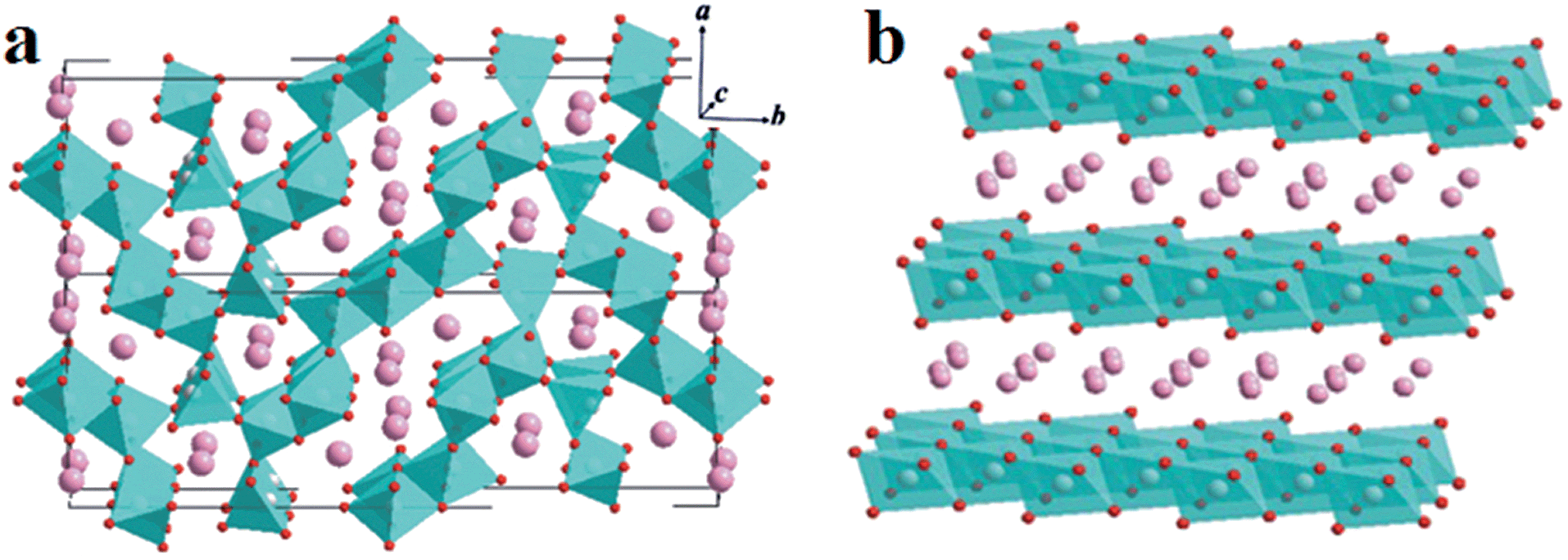 | ||
| Fig. 1 Schematic illustrations of the crystal structures of tunnel compounds (a) and layered compounds (b) in the Na–Mn–O system. | ||
As shown in Fig. 2, the morphology of precursor has no obviously influence on the original structure of sodium manganese oxide. The sodium manganese oxides with tunnel structure could be mainly obtained and simultaneously accompanied by the formation of layer structure compound. Morphologies and sizes of the as-prepared precursors and the corresponding Na0.50MnO2 were examined using SEM (Fig. 3). As can be seen from the figure, the morphologies of the sample have been maintained to some extent after the reaction. It must be pointed out that the surfaces of all products become rough, and a lot of debris is produced, especially for R-SMO and O-SMO after HTSSR.
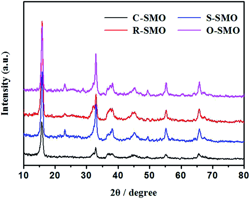 | ||
| Fig. 2 XRD patterns of the SMO samples (R = 0.5) after sintering at 600 °C obtained by HTSSR. | ||
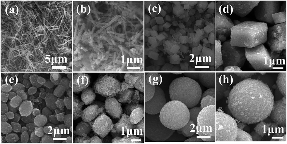 | ||
| Fig. 3 SEM images of different morphologies of the precursors (a, c, e and g) and corresponds to SMO samples (b, d, f and h) obtained from the HTSSR with R of 0.50 at 600 °C. | ||
3.2 The effect of R and sintering temperature
Fig. 4 and 5 shows XRD patterns and HR SEM images of the samples obtained under different temperatures with different R and the comparison of the samples obtained under different temperatures with the same R (0.50), respectively. As seen from Fig. 4, the peak separation phenomenon (PSP) could be clearly observed for SMO samples sintered at higher temperature. The crystal structures of the samples evolved into tunnel structure from lamellar phase, and the morphologies also changed into rod from the cube simultaneously, as shown in Fig. 5. | ||
| Fig. 4 XRD patterns of the samples obtained under different temperatures ((a) 500 °C; (b) 600 °C; (c) 800 °C) with different R and the comparison of the samples obtained under different temperatures with R of 0.50. (▲-Na0.91MnO2 phase; ★-layered phase; ●-tunnel phase; ■-Mn2O3). | ||
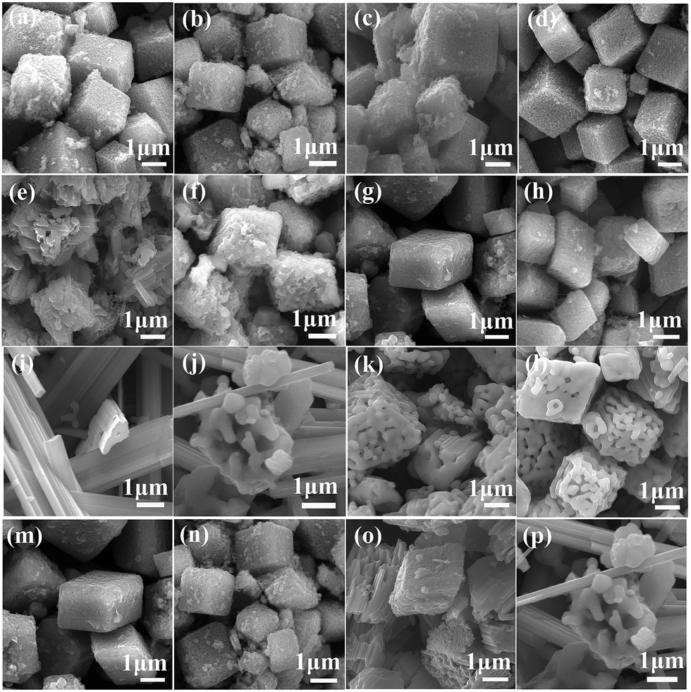 | ||
| Fig. 5 SEM images of the samples obtained under different temperatures (500 °C: (a), (b), (c), (d); 600 °C: (e), (f), (g), (h); 800 °C: (i), (j), (k), (l)) with different R and the comparison of the samples obtained under different temperatures ((m) 500 °C; (n) 600 °C; (o) 650 °C; (p) 800 °C) with R of 0.50. | ||
Both the morphologies and crystal structures of SMO samples are different with changed reaction temperature and sodium-to-manganese molar ratio (R). Fig. 4d and 5m, n, o and p show XRD patterns and SEM images of the samples obtained with different R at 500 °C, 600 °C, 650 °C and 800 °C, respectively. With increasing temperature, morphologies and crystal structures are certainly dissimilarity with different R. In our system, when the reaction temperature is less than 650 °C, the PSP did not occur during the R range (0.45–1.05), and morphologies can also keep well. When the reaction temperature is above 650 °C, the PSP phenomena could be observed, but also the morphologies of the samples transform partially into rods. The larger the R value, the more rods of SMO. When the R values is greater than or equal to 0.50, there are not only no PSP, but also SMO samples can maintain the morphologies, which is possibly caused by sodium component volatilization or segregation phenomenon at higher sintering temperature.30,31 In order to verify the hypothesis, we analyses the content of sodium and manganese in the SMO samples obtained under different temperatures with R of 0.70, as shown in Table 1. As can be seen from those data, more sodium are lost in SMO samples sintered at high temperatures and the reaction products change toward the low sodium component phase. This is why the phases obtained with high (1.05) and low (0.50) ratios at high temperature are different from those obtained at low temperature. The phase transformation is much easier when the R value is close to 0.50 with the sintering temperature at 650 °C. According to the present analytic results, the following schematic diagram will intuitively show us the influence of sintering temperature and R on the crystal structures of the SMO system (Scheme 1).
| wt% | Room temperature | 500 °C | 600 °C | 650 °C | 800 °C |
|---|---|---|---|---|---|
| Mn | 75.7 | 75.4 | 75.8 | 79.9 | 79.8 |
| Na | 24.3 | 24.6 | 24.2 | 20.1 | 20.2 |
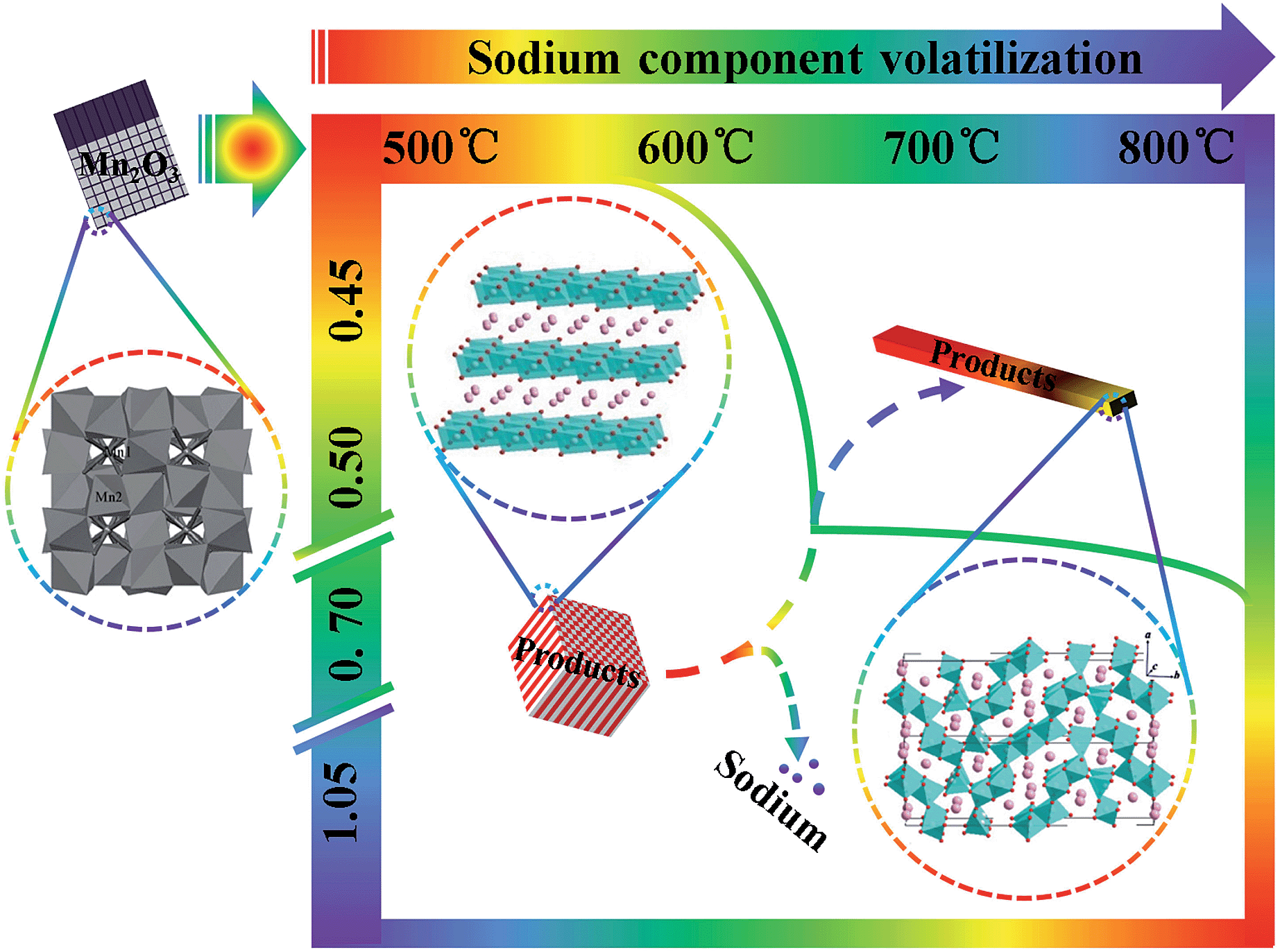 | ||
| Scheme 1 The influence of temperature and R on the crystal structure of the SMO system. | ||
3.3 Electrochemical performance
In order to compare the electrochemical performance of the Na0.50MnO2 with different morphologies, the samples were assembled to coin cells. All Li/Na0.50MnO2 cells were first discharged and subsequently charged. The highest charge–discharge profiles are shown in Fig. 6a. In all samples, a voltage plateau at about 3.0 V during the discharge is clearly observed. In this process, lithium ions insert into MnO6 layers and replace parts of sodium ions to maintain the framework of the layer structure.18 The charge curves are characterized by two distinct regions, a plateau at about 3.1 V corresponding to the deinsertion of lithium ion and another slight plateau ascribing to initial extraction of sodium ion. Compared with other samples, the O-SMO sample with the smallest grain size has the highest charge and discharge capacity; the S-SMO sample with the largest grain size has the lowest capacity. However, both of them have very large irreversible capacity owing to the impurity Mn2O3 in SMO. From the cycle curves as can be seen, the discharge capacities of four samples tend to be the same and decrease rapidly and unstable, especially for O-SMO and S-SMO samples that have more impurities. For different SMO samples, morphologies only play a leading role in the initial few cycles on electrochemical performance.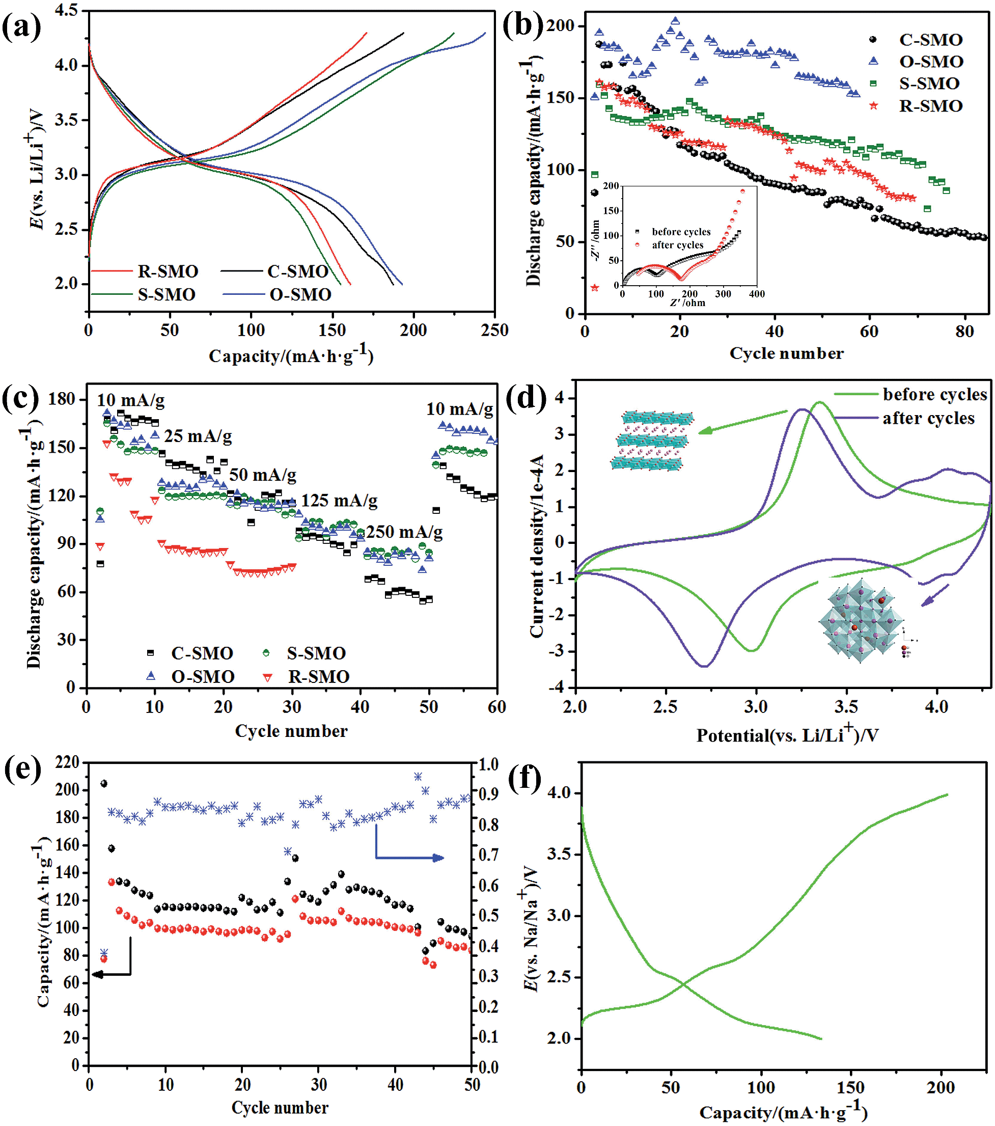 | ||
| Fig. 6 The highest charge–discharge profiles (a), cycle performance and impedance plots (insert image: for sample C-SMO before and after cycles) (b) and rate performance (c) of in the SMO samples with different morphologies; cyclic voltammograms at scan rate of 0.05 mV s−1 between 2.0 and 4.3 V for sample C-SMO before and after cycles (d). Cycle performance of sample C-SMO with R of 0.50 in the sodium ion batteries (e) and charge–discharge profiles (f). | ||
To elucidate the dependence of rate capability of the SMO samples, we applied 10, 25, 50, 125 and 250 for charge and discharge currents across the SMO electrode in the voltage range from 2.0 to 4.3 V. The discharge capacity obtained as a function of the cycle number for different discharge–charge rates is shown in Fig. 6c. The SMO samples with different morphologies exhibit analogous rate capability with discharge capacity. The performance of SMO mainly depends on the crystal structure, while the morphology plays an important role in the initial stage. The impurities make the long-term cycling unstable and lead to the capacity fading. In order to obtain the SMO with good electrochemical performance by the HTSSR, crystal structure must be first considered. The tunnel structure Na0.44MnO2 can be obtained for SMO samples sintered at high temperature with R close to 0.5 while monoclinic romanechite Na0.44MnO2 with bad electrochemical performance; the layer structure (P2 phase) Na0.67MnO2 can be maintained for SMO samples with R above 0.67 and the initial discharge capacity of 140 or more obtained at a current density of 10 in the sodium ion batteries, but it is not stable and the capacity decreases rapidly. For this, we have investigated cycle performance and charge–discharge profiles for sodium-ion battery, as shown in Fig. 6e and f. As can be seen from this information, SMO undergo at least one or more phase transformations leading to several voltage steps in their electrochemical profiles and not quite stable under cycling.
In order to further explore the reason why the stability of the material is not good, and decay rapidly, we examined voltammetry and electrochemical impedance spectra of the C-SMO system before and after cycles, respectively. Cyclic voltammograms were recorded for the electrodes in the voltage range of 2.0–4.3 V at a scan rate of 50 μV s−1. Voltammograms for the sample is shown in Fig. 6d. Before cycles, one couple of peaks in cathodic sweep and anodic sweep can be seen. It has an anodic peak at 3.35 V with a corresponding cathodic peak at 2.98 V; these peaks are assigned to a Mn3+/Mn4+ redox couple.32 However, there are two couples of peaks in cathodic sweep and anodic sweep for SMO samples after cycling, another hump anodic peak at 4.15 V with a corresponding cathodic peak at 3.93 V suggests that the transition from layer to spinel-like structure occurs during the charge–discharge process. This behavior is well consistent with the result reported by Bach et al.14 The peak potential difference between the cathodic peak and anodic peak are bigger for samples after cycling, indicating that the increasing irreversibility with the cycle of the electrode.
Meanwhile, the electrochemical impedance measurements were performed in the frequency range of 0.01–100 kHz, and the complex plane impedance plots are shown in Fig. 6b (insert image). Each impedance spectrum consists of two arcs at high and middle frequency and a tail inclined at approximately 45°and 60° to the real axis in the low frequency range. The high frequency semicircle is related to lithium ion migration through the SEI layer covered on the electrode materials, and the middle frequency semicircle is ascribed to charge-transfer through the electrode/electrolyte interface, and the low frequency line is assigned to solid state diffusion of the lithium ion in the materials matrix, namely the Warburg impedance. As can be seen from Fig. 6b, the internal resistance of the electrode diffusion impedance increased after cycling, with the charge and discharge repeatedly, the kinetics of system is almost entirely limited by the rate of chemical diffusion process of Li+ in the host material. The HTSSR is undoubtedly a very rude synthesis method and make sodium ions enter into the matrix lattice by a very overbearing process, which explains why the reaction products obtained covered broken crumbs. The structure becomes unstable even collapses when the sodium ions are extracted in the subsequent test cycle, which hindered the diffusion path of lithium ions.
4. Conclusion
In brief, SMO is synthesized by the HTSSR for tailored different morphologies and crystal structures through controlling the ratio of sodium-to-manganese and the heat-treatment temperature. For the uses of SMO in batteries, the SMO morphology only affects the battery performance in the initial stage, but its crystal structure can have significant impact on the performance.Acknowledgements
This work is financially supported by Chongqing Key Laboratory for Advanced Materials and Technologies of Clean Energies under cstc2011pt-sy90001, Start-up grant under SWU111071 from Southwest University and Chongqing Science and Technology Commission under cstc2012gjhz90002. The work is also supported by grants from the National Natural Science Foundation of China (no. 21063014, 21163021 and 51101130), Fundamental Research Funds for the Cental Universities (SWU 113079, XDJK2014C051).Notes and references
- A. R. Armstrong, A. J. Paterson, A. D. Robertson and P. G. Bruce, Chem. Mater., 2002, 14(2), 710–719 CrossRef CAS.
- F. Jiao, J. Bao, A. H. Hill and P. G. Bruce, Angew. Chem., 2008, 47(50), 9711–9716 CrossRef CAS PubMed.
- D. K. Kim, P. Muralidharan, H.-W. Lee, R. Ruffo, Y. Yang, C. K. Chan, H. Peng, R. A. Huggins and Y. Cui, Nano Lett., 2008, 8, 3498–3952 CrossRef PubMed.
- B. J. Liddle, S. M. Collins and B. M. Bartlett, Energy Environ. Sci., 2010, 3(9), 1339–1346 CAS.
- S. F. Tay and M. R. Johan, Ionics, 2010, 16(9), 859–863 CrossRef CAS.
- F. Cheng, H. Wang, Z. Zhu, Y. Wang, T. Zhang, Z. Tao and J. Chen, Energy Environ. Sci., 2011, 4(9), 3668–3675 CAS.
- S. Lee, Y. Cho, H.-K. Song, K. T. Lee and J. Cho, Angew. Chem., 2012, 51(35), 8748–8752 CrossRef CAS PubMed.
- Z. S. Zheng, Z. L. Tang, Z. T. Zhang and W. C. Shen, J. Inorg. Mater., 2003, 18(2), 257–263 CAS.
- F. Hu and M. M. Doeff, J. Power Sources, 2004, 129(2), 296–302 CrossRef CAS PubMed.
- X. Ma, H. Chen and G. Ceder, J. Electrochem. Soc., 2011, 158(12), A1307–A1312 CrossRef CAS PubMed.
- D. Yuan, W. He, F. Pei, F. Wu, Y. Wu, J. Qian, Y. Cao, X. Ai and H. Yang, J. Mater. Chem. A, 2013, 1(12), 3895–3899 CAS.
- H. Yoshida, N. Yabuuchi, K. Kubota, I. Ikeuchi, A. Garsuch, M. Schulz-Dobrick and S. Komaba, Chem. Commun., 2014, 50, 3677–3680 RSC.
- M. M. Doeffa, T. J. Richardsonb, J. Hollingswortha, C.-W. Yuan and M. Gonzales, J. Power Sources, 2002, 112, 294–297 CrossRef.
- S. Bach, J. P. Pereira-Ramos and P. Willmann, Electrochim. Acta, 2006, 52, 504–510 CrossRef CAS PubMed.
- J. Xu, D. H. Lee, R. J. Clément, X. Yu, M. Leskes, A. J. Pell, G. Pintacuda, X.-Q. Yang, C. P. Grey and Y. S. Meng, Chem. Mater., 2014, 26(2), 1260–1269 CrossRef CAS.
- J. Cabana, N. A. Chernova, J. Xiao, M. Roppolo, K. A. Aldi, M. S. Whittingham and C. P. Grey, Inorg. Chem., 2013, 52(15), 8540–8550 CrossRef CAS PubMed.
- M. M. Doeff, T. J. Richardson and L. Kepley, J. Electrochem. Soc., 1996, 143(8), 2507–2516 CrossRef CAS PubMed.
- P. Le Goff, N. Baffier, S. Bach, J. P. Pereira-Ramos and R. Messina, Solid State Ionics, 1993, 61(4), 309–315 CrossRef CAS.
- N. Yabuuchi, M. Kajiyama, J. Iwatate, H. Nishikawa, S. Hitomi, R. Okuyama, R. Usui, Y. Yamada and S. Komaba, Nat. Mater., 2012, 11(6), 512–517 CrossRef CAS PubMed.
- J. A. Saint, M. M. Doeff and J. Wilcox, Chem. Mater., 2008, 20, 3404–3411 CrossRef CAS.
- D. Su, C. Wang, H.-j. Ahn and G. Wang, Chem.–Eur. J., 2013, 19(33), 10884–10889 CrossRef CAS PubMed.
- E. Hosono, H. Matsuda, I. Honma, S. Fujihara, M. Ichihara and H. Zhou, J. Power Sources, 2008, 182(1), 349–352 CrossRef CAS PubMed.
- X. Zhou, K. R. Guduru and P. Mohanty, J. Mater. Chem. A, 2013, 1, 2757–2761 CAS.
- Y. Cao, L. Xiao, W. Wang, D. Choi, Z. Nie, J. Yu, L. V. Saraf, Z. Yang and J. Liu, Adv. Mater., 2011, 23(28), 3155–3160 CrossRef CAS PubMed.
- L. Gao, J. Ni, H. Wang and L. Zhao, Funct. Mater. Lett., 2013, 06(02), 1350012 CrossRef.
- M.-W. Xu, Y.-B. Niu, S.-J. Bao and C. M. Li, J. Mater. Chem. A, 2014, 2(11), 3749–3755 CAS.
- J. B. Fei, Y. Cui, X. H. Yan, W. Qi, Y. Yang, K. W. Wang, Q. He and J. B. Li, Adv. Mater., 2008, 20(3), 452–456 CrossRef.
- Y. Li and Y. Wu, Nano Res., 2009, 2, 54–60 CrossRef CAS.
- Z. Lu, R. A. Donaberger and J. R. Dahn, Chem. Mater., 2000, 12(12), 3583–3590 CrossRef CAS.
- F. Sauvage, E. Baudrin and J.-M. Tarascon, Sens. Actuators, B, 2007, 120, 638–644 CrossRef CAS PubMed.
- A. D. Tevar and J. F. Whitacre, J. Electrochem. Soc., 2010, 157(7), A870–A875 CrossRef CAS PubMed.
- Y. Wang, X. Shao, H. Xu, M. Xie, S. Deng, H. Wang, J. Liu and H. Yan, J. Power Sources, 2013, 226, 140–148 CrossRef CAS PubMed.
Footnote |
| † These authors contributed equally to this work. |
| This journal is © The Royal Society of Chemistry 2014 |