 Open Access Article
Creative Commons Attribution 3.0 Unported Licence
A fluorene-bridged double carbonyl/amine multiresonant thermally activated delayed fluorescence emitter for efficient green OLEDs†‡
Sen
Wu§
a,
Ya-Nan
Hu§
b,
Dianming
Sun
*a,
Kai
Wang
 b,
Xiao-Hong
Zhang
 *bc and
Eli
Zysman-Colman
 *a
*a
aOrganic Semiconductor Centre, EaStCHEM School of Chemistry, University of St Andrews, St Andrews, Fife KY16 9ST, UK. E-mail: eli.zysman-colman@st-andrews.ac.uk; sd235@st-andrews.ac.uk; Fax: +44-1334 463808; Tel: +44-1334 463826
bInstitute of Functional Nano & Soft Materials (FUNSOM), Joint International Research Laboratory of Carbon-Based Functional Materials and Devices, Soochow University, Suzhou, Jiangsu 215123, P. R. China. E-mail: xiaohong_zhang@suda.edu.cn
cJiangsu Key Laboratory of Advanced Negative Carbon Technologies, Soochow University, Suzhou, Jiangsu 215123, P. R. China
First published on 22nd December 2023
Abstract
Herein, we report a fluorene-bridged double carbonyl/amine-based MR TADF emitter DDiKTa-F, formed by locking the conformation of the previously reported compound DDiKTa. Using this strategy, DDiKTa-F exhibited narrower, brighter, and red-shifted emission. The OLEDs with DDiKTa-F emitted at 493 nm and showed an EQEmax of 15.3% with an efficiency roll-off of 35% at 100 cd m−2.
Thermally activated delayed fluorescence (TADF) materials have demonstrated great potential as next-generation emitters in organic light-emitting diodes (OLEDs) due to their ability to harness 100% of the excitons to produce light without the need for noble metals, present in phosphorescent OLEDs. TADF compounds convert non-emission triplet excitons into emissive singlets by an endothermic upconversion reverse intersystem crossing (RISC) process.1–4 The efficiency of the RISC process is governed in part by the singlet–triplet energy gap, ΔEST.5 A strongly twisted structure that effectively reduces the conjugation between donor and acceptor moieties is one strategy to achieve a small ΔEST as the exchange integral of the frontier molecular orbitals (FMOs) is small.4 However, a twisted structure exhibits significant excited-state structural relaxation, resulting in a broad emission characterized by a full width at half maximum (FWHM) higher than 70 nm.6 To compensate for the broad emission, filters or microcavities are required to improve color purity; however, this can, unfortunately, reduce the device efficiency.7
Multiresonant TADF (MR-TADF) emitters have emerged as a potential solution as these rigid structures exhibit narrowband emission. First reported by Hatakeyama et al., these compounds are p- and n-doped polycyclic aromatic hydrocarbons (PAHs).8 By employing this approach, the singlet and triplet excited states possess an alternating pattern of increasing and decreasing electron density compared to the ground state, thus enabling a small exchange integral and consequently a small ΔEST.9 The rigid structure and the short-range charge transfer (SRCT) nature of the excited states endow the MR-TADF compounds with bright, narrowband emission. Since the first report of MR-TADF emitters used in OLEDs in 2016, there has been intense research focused on expanding the chemical space encompassed by this class of emitters.10 In the original works of Hatakeyama et al., the n-dopants were boron atoms. It is possible to replace these with carbonyl groups, and the groups of Zysman-Colman11 Zhang,12 and Jiang and Liao13 were among the first to report examples of MR-TADF emitters containing this motif. Expanding the MR-TADF skeleton has been demonstrated to be an effective strategy for improving the performance of MR-TADF emitters,14 which has been less explored in carbonyl/amine systems.
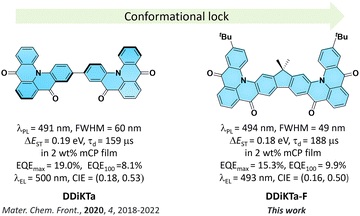
We have shown that the dimerization of the MR-TADF emitter, DiKTa, in DDiKTa, leads to a modest red-shift of the emission and the OLED showed an improved performance.15 In an attempt to further improve the device performance and reduce the structural motion inherent in DDiKTa, here, we envisioned annealing together two DiKTa units through a central 9,9-dimethyl-9H-fluorene bridge, DDiKTa-F. An analogue without the tert-butyl groups was also synthesized; however, purification proved too difficult owing to its poor solubility, likely due to its strong propensity to aggregate. Therefore, two tert-butyl groups were added to improve the solubility of this compound. DDiKTa-F was found to be brighter (photoluminescence quantum yield, ΦPL, of 78%) and emits with a narrower FWHM, of 49 nm compared to DDiKTa (ΦPL of 68% and FWHM of 59 nm) in 2 wt% doped films in 1,3-bis(carbazolyl)benzene (mCP). The device with DDiKTa-F showed an EQEmax of 15.3% emitting at a λEL of 493 nm (FWHM of 46 nm) with an improved efficiency roll-off at 100 cd m−2 of 35% compared to the devices with DDiKTa (56%)15 and DiKTa (44%) (Fig. 1).11
Theoretical calculations were out to investigate the effect of the incorporation of the fluorene bridge on the optoelectrical properties of the emitter compared to those of the reference, DiKTa. The geometry in the ground state was first optimized using density functional theory at the PBE0/6-31G(d,p) level. The frontier molecular orbitals (FMOs) are delocalized over the entire π-conjugated system, and the HOMO and LUMO show an alternating distribution pattern similar to that of DDiKTa, which is emblematic of MR-TADF compounds.15 The calculated HOMO and LUMO levels of DDiKTa-F are −5.94 and −2.32 eV, respectively. The HOMO–LUMO gap of 3.62 eV for DDiKTa-F is smaller than that of DDiKTa (ΔEHOMO–LUMO = 3.70 eV), reflecting an increased conjugation in the former. The locked structure of the molecule contributed to small geometric changes between the S0 and S1 states, as depicted in Fig. S15 (ESI†). Thus, it is expected that the emission spectrum will be narrow and that there will be a small Stokes shift. The emission spectra of both DiKTa and DDiKTa-F under vacuum were simulated using Frank–Condon analysis based on the S1–S0 transition at the TDA-DFT-PBE0/6-31G(d,p) level (Fig. S16, ESI†). The simulated spectrum of DiKTa shows an emission band peaking at λPL = 428 nm and a small FWHM = 14 nm, which closely aligns with the emission in hexane at λPL = 436 nm (FWHM = 21 nm). By contrast, the simulated emission spectrum of DDiKTa-F is red-shifted at λPL = 474 nm and is slightly broader (FWHM = 18 nm). We previously demonstrated that DFT calculations do not accurately predict the excited-state properties of MR-TADF emitters.16 Here, we employed SCS-ADC(2)/cc-pVDZ calculations to accurately model the excited states of DDiKTa-F.16 Difference density plots provide information on the changes in the electron density distribution in the excited states compared to that of the ground state. The difference density plots between S0 and each of the S1 and T1 states, calculated for the S0 optimized geometry, reveal that these excited states have SRCT characteristics typical of MR-TADF emitters. The calculated energies of the S1 and T1 states are 3.34 and 3.08 eV, respectively, which are lower than those of DiKTa (S1/T1 = 3.45/3.18 eV) and DDiKTa (S1/T1 = 3.39/3.12 eV), indicating that the emission in this compound should be red-shifted compared to the two reference emitters. The calculated ΔEST for DDiKTa-F is 0.26 eV, which is similar to those of DiKTa (0.26 eV)17 and DDiKTa (0.27 eV) (Fig. 2).15
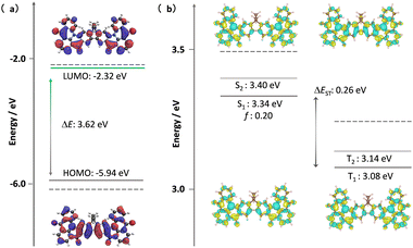 | ||
| Fig. 2 (a) Distribution of FMOs of DDiKTa-F, calculated at the PBE0/6-31G(d,p) level. (b) Difference density plots of S1/S2 and T1/T2 excited states, calculated at the SCS-ADC(2)/cc-pVDZ level for DDiKTa-F, where f is the oscillator strength. The dashed lines in each figure reference the calculated values of DiKTa at the same level of theory.17 | ||
The calculated spin–orbit coupling matrix element (SOCME) value between S1 and T1 is 0.37 cm−1 based on the T1-optimized geometry, while the SOCME values between S1 and the four closely lying higher triplet excited states range from 0.07 to 5.93 cm−1. In particular, the large 〈S1|ĤSOC|T3〉 value of 5.93 cm−1 is attributed to an n–π* transition localized on the carbonyl groups (Fig. S18, ESI†).17 These closely lying intermediate triplet states can participate in the RISC mechanism between T1 and S1 mediated by spin-vibronic coupling.18
The electrochemical properties of DDiKTa-F and DiKTa were investigated using cyclic voltammetry (CV) and differential pulse voltammetry (DPV) in deaerated DCM with 0.1 M tetra-n-butylammonium hexafluorophosphate as the supporting electrolyte (Fig. S19, ESI†). The CV results show that the oxidation is irreversible while the reduction is a quasi-reversible process. The oxidation and reduction potentials, Eox and Ered, determined, respectively, from the first oxidation and reduction peaks of the DPV, are 1.34 and −1.48 V vs. SCE. The corresponding HOMO/LUMO levels and energy gap (ΔE) are −5.68/−2.86 and 2.82 eV, respectively. The HOMO/LUMO are both destabilized compared to those of DDiKTa (−5.97/−3.07 eV) 15 and DiKTa (−6.10/−2.99 eV), implying that the fluorene bridge acts as an electron donor. As a result, ΔE was smaller than those of DDiKTa (2.90 eV) and DiKTa (3.03 eV).
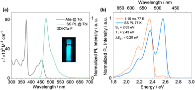
The absorption spectrum of the diluted toluene solution (10−5 M), shown in Fig. 3, exhibits two major bands. The band between 300 and 400 nm is linked to a π–π* transition delocalized over the whole skeleton, and the band at 375 nm is associated with the absorption of the central fluorene unit, both assigned from analysis of the TDA-DFT calculations (Fig. S17, ESI†). The lower energy band at 453 nm and shoulder at 431 nm are characteristics of an SRCT excited state transition for MR-TADF emitters (Fig. S17, ESI†). The SRCT band of DDiKTa-F is red-shifted and more intense (ε = 25 × 103 M−1 cm−1) than those of DDiKTa (λabs = 440 nm and ε = 10.4 × 10³ M−1 cm−1) and DiKTa (λabs = 433 nm and ε = 21 × 103 M−1 cm−1) due in part to its larger π-conjugation.15 The photoluminescence (PL) spectrum of DDiKTa-F in toluene, shown in Fig. 3a, has a peak maximum, λPL, of 476 nm, a shoulder at 511 nm, and an FWHM of 32 nm. The shoulder peak arises from the vibrational energy levels of the molecule, a typical characteristic of MR-TADF emitters.19,20 This emission is red-shifted compared to those of DDiKTa (λPL = 470 nm) and DiKTa (λPL = 453 nm).15 The emission of DDiKTa-F shows a modest positive solvatochromism (Fig. S20, ESI†), which is consistent with the emissive excited state of SRCT. The energies of the S1 and T1 states, determined from the onsets of the steady-state PL and phosphorescence spectra at 77 K in 2-MeTHF glass are 2.63 and 2.43 eV, respectively (Fig. 3b); thus, ΔEST = 0.20 eV. This value is similar in magnitude to those of DiKTa (0.22 eV in frozen toluene) and DDiKTa (0.21 eV in frozen toluene). The photoluminescence quantum yield, ΦPL, in toluene is 34%, which decreases to 31% upon exposure to air (Fig. S21, ESI†). No delayed emission was observed in toluene and the lifetime of the emission decay, τPL, was 4.5 ns (Fig. S21, ESI†), which is similar to that of DiKTa (τPL = 5.1 ns).11
With a view to employ DDiKTa-F as an emitter in OLEDs and to cross-compare their device performance with those of DDiKTa and DiKTa, we next investigated the photophysical properties of this emitter as doped films in mCP. The 2 wt% doped film of DDiKTa-F in mCP emits at 494 nm with a FWHM of 49 nm (Fig. 4a), an emission that is red-shifted compared to those of DDiKTa (λPL = 491 nm) and DiKTa (λPL = 467 nm) in 2 wt% doped films in mCP.17 We identified that 2 wt% doping provided the highest ΦPL of 78%, while the ΦPL decreased to 43% and the PL spectrum showed a pronounced red-shift from 491 to 507 nm when the doping concentration increased from 1 wt% to 10 wt% (Fig. S22, ESI†), implying that aggregation becomes an issue at this higher doping concentration. The ΦPL of the 2 wt% doped film in mCP decreased to 65% in air. The ΦPL of DDiKTa-F is slightly higher than those of both DiKTa (ΦPL = 46%) and DDiKTa (ΦPL = 65%) in 2 wt% doped films in mCP. At the same doping concentration, the ΦPL in the phosphine oxide-based hosts DPEPO and PPT are similar at 74 and 61% but the λPL are red-shifted at 510 and 511 nm, respectively, due to their higher polarity (Fig. S23, ESI†). The S1/T1 energies, determined from the onsets of the steady-state PL and delayed emission spectra at 77 K in the 2 wt% doped films in mCP, are 2.58/2.40 eV, resulting in a ΔEST of 0.18 eV (Fig. S26, ESI†), which is similar to that measured for 2-MeTHF glass. Temperature-dependent transient PL decay analysis reveals the expected increase in the delayed emission with increasing temperature, which confirms the TADF in the 2 wt% doped film in mCP (Fig. S24, ESI†). The emission decays with the associated average prompt (τp) and delayed (τd) lifetimes are 5.6 ns and 188 μs (Table 1), respectively. These values are intermediate to those of DDiKTa (τp = 5.9 ns and τd = 159 μs) and DiKTa (τp = 4.8 ns and τd = 242 μs); in air, the delayed emission of DDiKTa-F was not completely quenched (Fig. S25, ESI†). From these photophysical measurements, the RISC rate constant (kRISC) of DDiKTa-F was determined to be 2.16 × 10⁴ S−1 (Table S2, ESI†),21,22 which is intermediate to those of DDiKTa (kRISC = 1.77 × 10⁴ S−1) and DiKTa (kRISC = 2.52 × 10⁴ S−1).
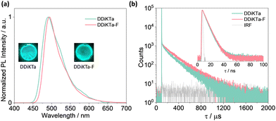 | ||
| Fig. 4 (a) SS PL spectra (λexc = 340 nm); (b) time-resolved PL decays of DDiKTa and DDiKTa-F measured using MCS (inset: TRPL decays of the prompt component measured using TCSPC); λexc = 375 nm. | ||
| Emitter | Φ PL /% | λ PL/nm | FWHM/nm | S1b/T1c/eV | ΔEST/eV | τ p, τd/ns, μs |
|---|---|---|---|---|---|---|
| a Φ PL was measured using an integrating sphere under nitrogen (λexc = 340 nm). b Obtained from the onset of the SS PL spectrum at 77 K. c Obtained from the onset of the delayed emission spectrum (1–10 ms) at 77 K (λexc = 340 nm). | ||||||
| DDiKTa-F | 78 | 494 | 49 | 2.58, 2.40 | 0.18 | 5.6, 188 |
| DDiKTa | 68 | 491 | 60 | 2.64, 2.45 | 0.19 | 5.9, 159 |
| DiKTa 17 | 46 | 467 | 46 | 2.75, 2.55 | 0.2011 | 4.8, 242 |
Having identified the potential of DDiKTa-F as an emitter for OLEDs, we next fabricated vacuum-deposited devices. The devices have the following architecture: ITO/TAPC (35 nm)/TCTA (10 nm)/CzSi (10 nm)/x wt% emitter/mCP (20 nm)/TmPyPB (40 nm)/LiF (1 nm)/Al (100 nm), where indium tin oxide (ITO) is the anode and 4,4′-cyclohexylidenebis[N,N-bis(4-methylphenyl)benzenamine] (TAPC) acts as the hole-transport layer. 9-(4-tert-butylphenyl)-3,6-bis(triphenylsilyl)-9H-carbazole (CzSi) is the exciton blocking layer, 1,3,5-tri(m-pyridin-3-ylphenyl)benzene (TmPyPB) acts as the electron-transporting material, and LiF modifies the work function of the aluminium cathode. The chemical structures of the materials used in these devices are shown in Fig. S27 (ESI†). The device stacks and their related performance are shown in Fig. 5 and Fig. S28 and S29 (ESI†), respectively.
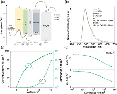 | ||
| Fig. 5 (a) Device configuration and energy levels for each layer; (b) electroluminescence spectra for devices; (c) J–V–L characteristics; and (d) EQE and CE versus luminance characteristics. | ||
The electroluminescence peak of the OLED, λEL of 493 nm and FWHM of 46 nm match those of the PL spectrum of the 2 wt% films in mCP (λPL = 494 nm and FWHM = 49 nm). The EL is narrower compared to the previously reported device with DDiKTa (9 wt% in DPEPO), which emitted at a λEL of 500 nm and had an FWHM of 59 nm.15 This small red-shifted emission compared to the SS PL in 2 wt% mCP film can be attributed to a combination of the use of the higher polarity DPEPO host and higher doping concentrations. By contrast, the EL is red-shifted compared to the device with DiKTa (3.5 wt% in mCP), which emitted at a λEL of 465 nm and had a FWHM of 59 nm.11 The corresponding Commission Internationale de l’Éclairage (CIE) coordinates are (0.16, 0.50) for the device with DDiKTa-F, which are close to those of the device with DDiKTa (0.18, 0.53), yet are red-shifted compared to the device with DiKTa (0.14, 0.18). The device with DDiKTa-F exhibited an EQEmax of 15.3%, which is similar to those of DDiKTa (19.0%) and DiKTa (14.7%). Gratifyingly, the efficiency roll-off was less severe, with an EQE of 100 cd m−2 at 9.9% for the device with DDiKTa-F, which was higher than those of DDiKTa (EQE100 = 8.1%) and DiKTa (EQE100 = 8.3%). This modestly improved efficiency roll-off can be explained by a higher figure of merit (FOM) that describes productive exciton utilization,  ,23 of 4.75 × 10³ s−1 for DDiKTa-F, compared to those of 4.71 × 10³ and 1.87 × 10³ s−1 for DDiKTa and DiKTa, respectively.
In conclusion, we demonstrated an easy-to-access synthetic route for constructing a p-extended dimeric MR-TADF emitter by fusing two DiKTa units onto a fluorene bridge. Through this strategy, the structural motion was reduced compared to that of the parent dimeric emitter DDiKTa. This led to an improved ΦPL of 79% and a red-shifted and narrower emission at 494 nm (FWHM = 49 nm) in 2 wt% doped films in mCP. Moreover, the ΔEST decreased to 0.18 eV, which led to a modest improvement in kRISC from 1.77 × 10⁴ S−1 to 2.16 × 10⁴ S−1. The device with DDiKTa-F exhibited an EQEmax of 15.3% and emission at 493 nm. Owing to the faster kRISC, the device exhibited a smaller efficiency roll-off of 35% at 100 cd m−2 than the devices with DDiKTa (56%) and DiKTa (44%). This emitter design, annelating multiple MR-TADF cores about a central fluorene, provides a simple method to maintain narrowband emission in MR-TADF compounds while simultaneously enhancing the ΦPL and kRISC.
S. W. thanks the China Scholarship Council (201906250199) for support. D.S. acknowledges support from the Royal Academy of Engineering Enterprise Fellowship (EF2122-13106). E. Z.-C. thanks the Engineering and Physical Sciences Research Council (EP/W015137/1, EP/W007517) for support. X.-H. Z. acknowledges support from the National Natural Science Foundation of China (Grant No. 52130304, 51821002) and the Collaborative Innovation Center of Suzhou Nano Science & Technology.
Conflicts of interest
There are no conflicts to declare.References
- C. W. Tang and S. A. VanSlyke, Appl. Phys. Lett., 1987, 51, 913 CrossRef CAS.
- M. A. Baldo, D. F. O’Brien, Y. You, A. Shoustikov, S. Sibley, M. E. Thompson and S. R. Forrest, Nature, 1998, 395, 151–154 CrossRef CAS.
- A. Endo, K. Sato, K. Yoshimura, T. Kai, A. Kawada, H. Miyazaki and C. Adachi, Appl. Phys. Lett., 2011, 98, 083302 CrossRef.
- Y. Tao, K. Yuan, T. Chen, P. Xu, H. Li, R. Chen, C. Zheng, L. Zhang and W. Huang, Adv. Mater., 2014, 26, 7931–7958 CrossRef CAS PubMed.
- H. Uoyama, K. Goushi, K. Shizu, H. Nomura and C. Adachi, Nature, 2012, 492, 234–238 CrossRef CAS PubMed.
- Y. J. Cho, S. K. Jeon, S.-S. Lee, E. Yu and J. Y. Lee, Chem. Mater., 2016, 28, 5400–5405 CrossRef CAS.
- A. C. Arsenault, D. P. Puzzo, I. Manners and G. A. Ozin, Nat. Photonics, 2007, 1, 468–472 CrossRef CAS.
- T. Hatakeyama, K. Shiren, K. Nakajima, S. Nomura, S. Nakatsuka, K. Kinoshita, J. Ni, Y. Ono and T. Ikuta, Adv. Mater., 2016, 28, 2777–2781 CrossRef CAS PubMed.
- H. Jiang, J. Jin and W. Y. Wong, Adv. Funct. Mater., 2023, 33, 2306880 CrossRef CAS.
- R. K. Konidena and K. R. Naveen, Adv. Photonics Res., 2022, 3, 2200201 CrossRef CAS.
- D. Hall, S. M. Suresh, P. L. dos Santos, E. Duda, S. Bagnich, A. Pershin, P. Rajamalli, D. B. Cordes, A. M. Z. Slawin, D. Beljonne, A. Köhler, I. D. W. Samuel, Y. Olivier and E. Zysman-Colman, Adv. Opt. Mater., 2020, 8, 1901627 CrossRef CAS.
- X. Li, Y.-Z. Shi, K. Wang, M. Zhang, C.-J. Zheng, D.-M. Sun, G.-L. Dai, X.-C. Fan, D.-Q. Wang, W. Liu, Y.-Q. Li, J. Yu, X.-M. Ou, C. Adachi and X.-H. Zhang, ACS Appl. Mater. Interfaces, 2019, 11, 13472–13480 CrossRef CAS PubMed.
- Y. Yuan, X. Tang, X.-Y. Du, Y. Hu, Y.-J. Yu, Z.-Q. Jiang, L.-S. Liao and S.-T. Lee, Adv. Opt. Mater., 2019, 7, 1801536 CrossRef.
- C. Zhou, A. Shatskiy, A. Z. Temerdashev, M. D. Kärkäs and P. Dinér, Commun. Chem., 2022, 5, 92 CrossRef CAS PubMed.
- D. Sun, S. M. Suresh, D. Hall, M. Zhang, C. Si, D. B. Cordes, A. M. Z. Slawin, Y. Olivier, X. Zhang and E. Zysman-Colman, Mater. Chem. Front., 2020, 4, 2018–2022 RSC.
- D. Hall, J. C. Sancho-García, A. Pershin, G. Ricci, D. Beljonne, E. Zysman-Colman and Y. Olivier, J. Chem. Theory Comput., 2022, 18, 4903–4918 CrossRef CAS PubMed.
- S. Wu, L. Zhang, J. Wang, A. Kumar Gupta, I. D. W. Samuel and E. Zysman-Colman, Angew. Chem., Int. Ed., 2023, 62, e202305182 CrossRef CAS PubMed.
- T. J. Penfold, E. Gindensperger, C. Daniel and C. M. Marian, Chem. Rev., 2018, 118, 6975–7025 CrossRef CAS PubMed.
- Y. Kondo, K. Yoshiura, S. Kitera, H. Nishi, S. Oda, H. Gotoh, Y. Sasada, M. Yanai and T. Hatakeyama, Nat. Photon., 2019, 13, 678 CrossRef CAS.
- X. Qiu, G. Tian, C. Lin, Y. Pan, X. Ye, B. Wang, D. Ma, D. Hu, Y. Luo and Y. Ma, Adv. Opt. Mater., 1845, 9, 20200 Search PubMed.
- K. Masui, H. Nakanotani and C. Adachi, Org. Electron., 2013, 14, 2721–2726 CrossRef CAS.
- Y. Tsuchiya, S. Diesing, F. Bencheikh, Y. Wada, P. L. dos Santos, H. Kaji, E. Zysman-Colman, I. D. W. Samuel and C. Adachi, J. Phys. Chem. A, 2021, 125, 8074–8089 CrossRef CAS PubMed.
- S. Diesing, L. Zhang, E. Zysman-Colman and I. Samuel, ChemRxiv, 2023, preprint, DOI:10.26434/chemrxiv-2023-c0hgg.
Footnotes |
| † Electronic supplementary information (ESI) available: 1H and 13C-NMR spectra, HRMS, EA and HPLC of all target compounds; supplementary computational, photophysical device data. See DOI: https://doi.org/10.1039/d3cc05761e |
| ‡ The research data supporting this publication can be accessed at https://doi.org/10.17630/87972673-41de-4d34-9fd1-cfd23e633741 |
| § Equal contribution. |
| This journal is © The Royal Society of Chemistry 2024 |

