Construction of single-atom copper sites with low coordination number for efficient CO2 electroreduction to CH4†
Shaomin
Wei
,
Xingxing
Jiang
,
Congyi
He
,
Siyu
Wang
,
Qi
Hu
,
Xiaoyan
Chai
,
Xiangzhong
Ren
,
Hengpan
Yang
 * and
Chuanxin
He
 *
*
Department of Chemistry, College of Chemistry and Environmental Engineering, Shenzhen University, Shenzhen 518060, Guangdong, China. E-mail: hecx@szu.edu.cn; hpyang@szu.edu.cn; Tel: +86-0755-26536141
First published on 8th December 2021
Abstract
Generally speaking, the preparation of single-atom catalysts always requires harsh conditions such as high-temperature pyrolysis or strong acid etching. In this manuscript, a simple and effective plasma-activated strategy is employed to synthesize a MOF-based single-atom copper catalyst. The bombardment of plasma forms abundant oxygen vacancies and significantly increases the number of low-coordinated catalytically active copper sites. Moreover, plasma treatment also creates a hierarchically porous structure, which can effectively adsorb the reactant molecules. The synergistic effect of the porous structure and low-coordinated copper sites dramatically improves the activity of CO2 electroreduction to CH4 with a maximum faradaic efficiency of 75.3%. Furthermore, the total faradaic efficiency of carbon-containing products (CO, CH4 and C2H4) can reach as high as 96.5% with a partial current density of 47.8 mA cm−2. Density functional theory (DFT) calculations confirm that the low-coordinated copper sites can be beneficial for the formation and further reduction of the key intermediate to CH4. This strategy provides a successful example for the preparation of single-atom catalysts under mild conditions.
Due to the advantage of high energy density, fossil fuels are still the leading choices in the global energy supply system. Unfortunately, the consumption of fossil fuels over several centuries is inevitably accompanied by serious direct environmental damage and massive CO2 emission.1 The growing atmospheric CO2 levels bring forth irreversible environmental changes, global warming, ocean acidification and other issues, thereby threatening the sustainable development of mankind.2 Therefore, energy conversion and storage technology based on electrochemical technology have received widespread attention.
Specifically, the electrocatalytic CO2 reduction technology can utilize the greenhouse gas CO2 and the surplus electricity from renewable energy to produce carbon-based fuels (such as C2H5OH, CH4) and bulk chemicals (such as CO).3–5 The electrochemical reduction of CO2 provides an effective technique for the development of renewable and environment-friendly energy utilization systems. However, the special linear structure of CO2 endows it with high chemical inertia and stability.6 Hence, one of the key research fields of CO2 electroreduction technology is to design and prepare efficient and stable electrocatalysts to activate CO2 molecules.7 According to the different active components, CO2 electroreduction catalysts can be divided into noble metal catalysts8–14 (e.g., Au, Ag, Pd), non-noble metal catalysts15–21 (e.g., Fe, Co, Ni, Cu, Zn, Sn) and metal-free catalysts.22–27 Based on the size and dispersion of catalytically active species, they can also be divided into nano-structure catalysts and atom-scale catalysts.
In recent years, single-atom catalysts have shown great prospects in CO2 electroreduction.28–34 Single-atom catalysts usually contain isolated metal atoms, which are highly dispersed on certain supports, including metal oxides, two-dimensional layered crystals and carbon materials. The distance between the isolated metal atoms is long enough to prevent the formation of a significant metal lattice.30 This unique structure can maximally improve the utilization rate of metal atoms and greatly increase the selectivity of target products (e.g., CO, CH4) in CO2 electroreduction. The preparation of single-atom catalysts usually involves high-temperature heat treatment of specific precursors, e.g., metal–organic frameworks (MOFs) and crosslinked polymers.31 The pyrolysis of MOFs or polymer precursors could easily cause the generation of metal single atoms as well as metal nanoparticles. These nanoparticles always need to be removed by acid etching to obtain a single-atom catalyst, which is not in accordance with the basic principle of atom economy.35
Based on the above reasons, we employed a kind of conjugated copper(II) catecholate MOFs (denoted as CuDBC) as potential catalysts for CO2 electroreduction. After simple plasma gas bombardment, this Cu-DBC material can be utilized as a high-efficiency electrocatalyst for CO2 reduction, involving no high-temperature pyrolysis. In the plasma-activated procedure, Cu-DBC retained the abundant pores, which could adsorb CO2 molecules and accelerate the transfer of reactants to the active sites. In addition, the high energy plasma creates a large number of low-coordinated Cu sites, which could efficiently convert CO2 into CH4.
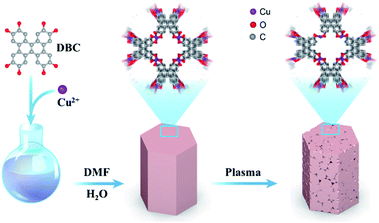
As described in Scheme 1, the CuDBC precursor was firstly synthesized from DBC ligand and Cu(OAc)2 in a mixed solvent of deionized water and N,N-dimethylformamide (DMF) at 85 °C in a nitrogen atmosphere. In the CuDBC precursor, Cu2+ could coordinate with four O atoms to form the Cu–O4–C moiety (Fig. S1†).36 However, ligand doped copper sites with high coordination number can hardly be directly utilized as efficient catalytic sites for CO2 reduction, due to the steric hindrance effect that blocks the adsorption of CO2 molecules and intermediates on the inner Cu sites.37 Consequently, the Cu-DBC precursor was further activated using high energy plasma treatments with 100 W O2 for 20 minutes. The as-synthesized powder was named plasma activated CuDBC (PA-CuDBC-1). The microstructures of the CuDBC precursor and PA-CuDBC-1 were characterized via scanning electron microscopy (SEM) and transmission electron microscopy (TEM). As revealed in Fig. 1a, b and S2,† CuDBC shows long and crystallized nanorods with approximately several micrometres length and around 100 nanometers width. In addition, CuDBC has a flat and smooth surface, and no obvious holes are found on the crystal surface.
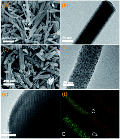 | ||
| Fig. 1 (a) SEM and (b) TEM images of pristine CuDBC; (c) SEM and (d and e) HR-TEM images of PA-CuDBC-1, respectively; (f) EDS mapping images for C, O, and Cu of PA-CuDBC-1. | ||
After the plasma treatment, PA-CuDBC-1 retains the overall structure of long and crystallized nanorods (Fig. 1c) of CuDBC. Compared with the flat and smooth surface of CuDBC, the surface of PA-CuDBC-1 tends to be chapped and rough after plasma treatment (Fig. 1c, d and S3†). It is notable that plasma bombardment did not cause fundamental damage to the crystal structure of the CuDBC, which could be proved by the obvious lattice stripes in high resolution TEM images (Fig. 1e). Furthermore, energy dispersive spectroscopy mapping (EDS, Fig. 1f) exhibits the uniform dispersion of C, O and Cu elements on the PA-CuDBC-1 skeleton. Therefore, the 20 minute plasma treatment of PA-CuDBC-1 did not lead to the aggregation of copper single sites into copper nanoparticles.
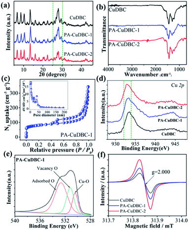
X-ray diffraction (XRD) was also employed to uncover the potential structural change of PA-CuDBC-1. XRD patterns (Fig. 2a) of CuDBC and PA-CuDBC-1 show similar sharp peaks, indicating the high crystallinity of both samples. No obvious diffraction peaks of metallic Cu are observed, ruling out the generation of Cu nanoparticles in plasma activation. PA-CuDBC-1 was further treated with 100 W O2 plasma for another 20 minutes, and named PA-CuDBC-2. Compared to CuDBC and PA-CuDBC-1, the XRD pattern of PA-CuDBC-2 (Fig. 2a, inside the dashed frame) presents significant weakness in the diffraction peaks between 25° and 30°.36 Besides, some small Cu nanoparticles can be seen in the TEM images of PA-CuDBC-2, implying the disintegration of the metal organic frameworks and aggregation of Cu ions using 40 minute O2 plasma bombardment (Fig. S4†). In the Fourier transform infrared spectroscopy (FT-IR, Fig. 2b) of the three samples, two major peaks around 1580 and 1395 cm−1 are observed, indicating the C–O asymmetric and symmetric stretching vibrations in the CuDBC structure.38 Moreover, the N2 sorption isotherms of PA-CuDBC-1 manifest an apparent hysteresis loop at high relative pressures, which is attributed to the type-IV or mesoporous structure. The curve of pore size distribution also reveals the abundant mesopores in PA-CuDBC-1 (Fig. 2c). In contrast, CuDBC displays typical type I adsorption and desorption isotherms (Fig. S5†). The Brunauer–Emmett–Teller (BET) surface area is 86.0 and 265.1 m2 g−1 for CuDBC and PA-CuDBC-1, respectively. It is worth noting that PA-CuDBC-2 (Fig. S6†) only has a specific surface area of 137.0 m2 g−1, because of the destruction of micropores under continuous plasma bombardment.
To explore the chemical composition and coordination environment, all three samples were characterized by X-ray photoelectron spectroscopy (XPS). The XPS survey spectra of the three samples prove the coexistence of Cu, O and C (Fig. S7†). The Cu 2p fine spectra (Fig. 2d and S8†) of the three samples display a characteristic peak at around 933 eV, corresponding to Cu 2p3/2 for Cu2+ species. Compared to the values of CuDBC, a slight binding energy shift can be detected in PA-CuDBC-1, which could be attributed to the lower oxygen coordination number around copper sites. The high-resolution O 1s spectra of the three samples (Fig. 2e) can be deconvoluted into three subpeaks of Cu–O, vacancy O and adsorbed O, respectively. Specifically, PA-CuDBC-1 shows a larger peak area of vacancy O than CuDBC and PA-CuDBC-2 (Fig. S9–S11†). This binding energy shift and vacancy O peaks in XPS spectra manifest the improvement of oxygen vacancies in plasma activated CuDBC samples.39 Electron paramagnetic resonance (EPR) spectra (Fig. 2f) were also obtained to further study the oxygen vacancy. PA-CuDBC-1 and PA-CuDBC-2 exhibit very strong signals at g = 2.000 induced by the oxygen vacancy.37,39 These abundant oxygen vacancies and low coordinated copper sites (Fig. S12†) were caused by the bombarding of high energy O2 plasma, which have great potential in CO2 electro-reduction.
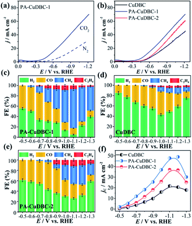
As mentioned above, PA-CuDBC-1 not only has a hierarchically porous structure, but also possesses a large number of low coordination copper single-atom sites, which might have great potential in CO2 electroreduction. To evaluate and compare the CO2 reduction activities, all the three samples are powdered and drop-cast on a piece of carbon paper via polymer binders to obtain a useful working electrode in a two-chamber electrolytic cell. Linear sweep voltammetry (LSV) of all samples was conducted in a N2- or CO2-saturated 0.5 M KHCO3 solution with a scan rate of 0.01 V s−1. As displayed in Fig. 3a, the LSV curve of PA-CuDBC-1 increases significantly around −0.5 VRHE cathode potential in the N2-saturated electrolyte, due to hydrogen evolution, while the current density increases sharply at approximately −0.35 VRHE potential in the CO2-saturated electrolyte. Furthermore, much higher current density could be observed in the CO2-saturated solution from −0.35 VRHE to −1.15 VRHE cathode potential, due to the additional CO2 reduction currents of the PA-CuDBC-1 catalyst.30 Notably, PA-CuDBC-1 shows much higher current densities in CO2-saturated 0.5 M KHCO3 solution than CuDBC and PA-CuDBC-2, e.g., 22.2 mA cm−2 (CuDBC), 30.1 mA cm−2 (PA-CuDBC-2) and 36.5 mA cm−2 (PA-CuDBC-1) at −0.9 VRHE (Fig. 3b). The current densities indicate the enhanced catalytic activities of PA-CuDBC-1 in CO2 reduction.
In LSV curves, the current densities were all increased in CO2-saturated KHCO3 solution, demonstrating the existence of the CO2 reduction procedure. To determine the product distribution in CO2 electroreduction, potentiostatic electrolysis using CuDBC, PA-CuDBC-1 and PA-CuDBC-2 catalysts with cathode potentials from −0.5 VRHE to −1.3 VRHE was conducted in 0.5 M KHCO3 electrolyte. The reduction products were qualitatively and quantitatively detected by nuclear magnetic resonance (NMR) and gas chromatography (GC). In this research, no (or only trace) liquid products were observed throughout the applied potentials. For all three samples, H2, CO, CH4 and C2H4 are the main reduction products with ∼100% total faradaic efficiencies (FE, Fig. 3c–e). For PA-CuDBC-1 (Fig. 3c), H2 and CO are the dominant reduction products at applied potentials before −0.7 VRHE. PA-CuDBC-1 brings forth the highest CO FE (52.6%) at −0.5 VRHE and a H2 FE of 33.5%, along with a CH4 FE of 12.4% and a little amount of C2H4 (1.5%). When the potentials increased to −0.8 VRHE and −0.9 VRHE applied potential, the H2 FE declined to 30.8% and 28.4%, and the CO FE decreased to 37.2% and 27.0%, respectively. In contrast, the faradaic efficiencies of CH4 and C2H4 improve from 2.9% to 26.5% and 0% to 5.5%, when the potentials increase from −0.6 VRHE to −0.8 VRHE. If the applied potentials are higher than −0.9 VRHE, the main reduction product turns out to be CH4. PA-CuDBC-1 produces the highest CH4 FE of 75.3% at −1.1 VRHE along with a C2H4 FE of 7.1%, and the CO FE and H2 FE reduce to 14.1% and 3.5%, respectively. Under the same reaction conditions using CuDBC catalyst, the corresponding faradaic efficiencies of H2, CO, CH4 and C2H4 are also summarized in Fig. 3d. H2 and CO are the major products in the whole range of applied potentials, with a small amount of CH4 and C2H4. The highest faradaic efficiency of CO is 44.9% at −1.0 VRHE, and the highest faradaic efficiency of CH4 is 12.1% at −1.2 VRHE cathode potential. PA-CuDBC-2 exhibits similar product distribution and tendency to PA-CuDBC-1 (Fig. 3e). The CH4 FE reaches the maximum value (37.3%) at −1.2 VRHE, with a CO FE of 20.6%, a C2H4 FE of 10.1% and a H2 FE of 32.0%. Although PA-CuDBC-2 achieved significantly lower CH4 FE than CuDBC-1, it also achieved the highest C2H4 FE (12.0%) among the three catalysts.
Intriguingly, both PA-CuDBC-1 and PA-CuDBC-2 engender obviously higher faradaic efficiencies of carbon-containing products than CuDBC. As demonstrated above, the high energy plasma created a plenty of oxygen vacancies and low coordinated copper sites in PA-CuDBC-1 and PA-CuDBC-2. These low coordinated metal sites have more vacant coordination sites and less steric hindrance, which might favour the CO2 adsorption and activation.40,41 Besides, the current densities are presented against the corresponding overpotentials to obtain a Tafel plot (Fig. 4a). A 163 mV dec−1 Tafel slope is observed for PA-CuDBC-1, which is related to the first electron transfer to CO2 molecule.25,26 In addition, the Tafel slope for PA-CuDBC-1 (163 mV dec−1) is much lower than those of PA-CuDBC-2 (262 mV dec−1) and CuDBC (388 mV dec−1), indicating the faster initial electron transfer to CO2 molecules and higher activity in CO2 reduction. Electrochemical impedance spectroscopy (EIS) characterizations are also conducted to explore the electrical conductivity of the three catalysts.11 The resistance value is calculated according to the EIS (Fig. 4b), which proves the lowest charge-transfer resistance of PA-CuDBC-1 compared to PA-CuDBC-2 and CuDBC, further proving that PA-CuDBC-1 is beneficial for the electron transfer in CO2 reduction.
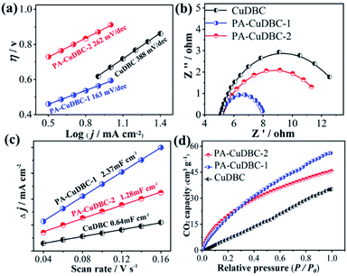 | ||
| Fig. 4 (a) Tafel plots, (b) EIS and (c) ECSA of the three samples; (d) CO2 adsorption capacity of the three samples. | ||
Besides the higher faradaic efficiencies, the partial current densities of all carbon-containing products (CO, CH4 and C2H4) for PA-CuDBC-1 are also significantly larger than those of CuDBC and PA-CuDBC-2 (Fig. 3f). For example, 26.5, 36.8 and 47.8 mA cm−2 partial current densities were obtained using CuDBC, PA-CuDBC-1 and PA-CuDBC-2, respectively, at −1.1 VRHE applied potential. As characterized above, PA-CuDBC-1 has a larger specific surface area and hierarchically porous structure, because of the plasma bombardment (Fig. 1c and 2c). This superior structure can bring about much higher electrochemical active area (ECSA, Fig. 4c and S13†), where the CO2 reduction procedure occurs. The hierarchically porous structure also increases the adsorption capacity of CO2 molecules (Fig. 4d) and enhances the CO2 content around the copper sites for CO2 reduction reaction,26 eventually leading to the higher partial current densities of PA-CuDBC-1. Since the durability is also an important specification for CO2 electro-reduction,6–8 the long-term electrolysis of PA-CuDBC-1 was carried out at −1.1 VRHE applied potential for 50 hours (Fig. S14†). The total current density can retain a stable value of ∼52 mA cm−2 with slight decrease, indicating the excellent stability. After all the electrolysis experiments, SEM, TEM, XRD and FTIR analysis of the PA-CuDBC-1 sample were conducted. As shown in Fig. S15,† PA-CuDBC-1 still retained the structure of long and crystallized nanorods. There are no obvious metallic clusters or nanoparticles in the SEM or TEM images, and no diffraction peaks of metallic Cu are observed in XRD patterns, excluding the accumulation of single-atom Cu sites during electrolysis. Moreover, the characteristic peaks of C–O stretching vibration are still observed in the FTIR, proving the good stability of PA-CuDBC-1 during CO2 reduction. Therefore, PA-CuDBC-1 is indeed a stable and high-performance catalyst for CO2 electro-reduction.
According to Fig. 3c–e, CO and CH4 are the main products with only a small fraction of C2H4 from CO2 reduction using all the three samples. Since copper single atoms are the dominant active sites in CuDBC, PA-CuDBC-1 and PA-CuDBC-2, the large distance between copper atoms in these catalysts can hardly facilitate effective C–C bond coupling to produce C2+ products.16,17 PA-CuDBC-2 can generate the highest C2H4 FE (12.0%) among the three catalysts, attributed to the aggregation of Cu ions into Cu nanoparticles during long-time plasma bombardment. As for the production of CH4, adsorbed CO on active sites (*CO) has been reported to be a crucial reaction intermediate. The adsorbed *CO intermediate would then go through an electro-hydrogenation procedure to *CHO, eventually leading to the generation of CH4.41–43 Density functional calculation (DFT) based computational methods are introduced to understand the high selectivity of CH4 on PA-CuDBC-1. The Cu active sites of CuDBC were simplified and simulated as a Cu–O4–C (Fig. S16†) structure within a single-layer, while the low-coordinated Cu sites in PA-CuDBC-1 and PA-CuDBC-2 were modelled as Cu–O3–C (Fig. S17†) and Cu–O2–C (Fig. S18†) structure within a single-layer. According to our calculations, the transformation from CO2 into *COOH with the three structures are all uphill type in the free energy profiles, indicating the rate determining step.19–21 Cu–O2–C presents the lowest free-energy (ΔG, 0.31 eV) for this procedure, followed by Cu–O3–C (0.43 eV), and Cu–O4–C (1.02 eV). The *COOH intermediate would be further reduced to a *CO and *CHO species with a coupled proton and a transferred electron. Cu–O2–C and Cu–O3–C both exhibit much lower energy barriers than Cu–O4–C. Therefore, the lower energy barriers of Cu–O2–C and Cu–O3–C are well consistent with the low-coordinated copper sites in PA-CuDBC-1, leading to the highest CH4 selectivity in CO2 electro-reduction (Fig. 5).
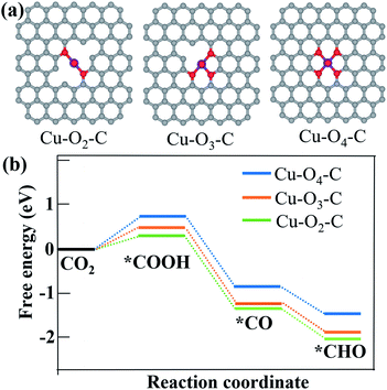 | ||
| Fig. 5 (a) Optimized structures of Cu–O2–C, Cu–O3–C and Cu–O4–C moieties; (b) free energy diagram of CO2 to *COOH, *CO and *CHO intermediates on Cu–O2–C, Cu–O3–C and Cu–O4–C structures. | ||
In conclusion, a MOF-derived single-atom Cu catalyst, PA-CuDBC-1, was prepared via simple and effective plasma treatment under mild conditions. PA-CuDBC-1 possesses abundant low-coordinated copper sites and a hierarchically porous structure, which was utilized as an efficient catalyst for electrochemical reduction of CO2. PA-CuDBC-1 could produce the highest CH4 FE of 75.3% at −1.1 VRHE applied potential along with a C2H4 FE of 7.1%, a CO FE of 14.1% and a H2 FE of 3.5%, respectively. The total faradaic efficiency of carbon-containing products (CO, CH4 and C2H4) can reach 96.5% with a partial current density of 47.8 mA cm−2, which are significantly better than that of pristine CuDBC without plasma activation. DFT calculations demonstrate that the low-coordinated copper sites, Cu–O3–C and Cu–O2–C, can decrease the energy barrier for the formation of the key intermediate, and accelerate the kinetic process for the reduction of CO2 to CH4. This strategy provides a good example of efficient catalysts for CO2 reduction and also shows feasibility for the preparation of other single-atom catalysts.
Conflicts of interest
There are no conflicts to declare.Acknowledgements
Financial support from the National Natural Science Foundation of China (22172099, 21975162, 51902209), Natural Science Foundation of Guangdong Province (2020A1515010840) and Shenzhen Government’s Plan of Science and Technology (RCBS20200714114819161, JCYJ20190808111801674, JCYJ20170818144659020) is gratefully acknowledged.Notes and references
- G. Wang, J. Chen, Y. Ding, P. Cai, L. Yi, Y. Li, C. Tu, Y. Hou, Z. Wen and L. Dai, Chem. Soc. Rev., 2021, 50, 4993–5061 RSC.
- Y. Wang, H. Su, Y. He, L. Li, S. Zhu, H. Shen, P. Xie, X. Fu, G. Zhou, C. Feng, D. Zhao, F. Xiao, X. Zhu, Y. Zeng, M. Shao, S. Chen, G. Wu, J. Zeng and C. Wang, Chem. Rev., 2020, 120, 12217–12314 CrossRef CAS.
- Y. Zhou, F. Che, M. Liu, C. Zou, Z. Liang, P. DeLuna, H. Yuan, J. Li, Z. Wang, H. Xie, H. Li, P. Chen, E. Bladt, R. Quintero-Bermudez, T. K. Sham, S. Bals, J. Hofkens, D. Sinton, G. Chen and E. H. Sargent, Nat. Chem., 2018, 10, 974–980 CrossRef CAS PubMed.
- M. Liu, Y. Pang, B. Zhang, P. Luna, O. Voznyy, J. Xu, X. Zheng, C. Dinh, F. Fan, C. Cao, F. Arquer, T. Safaei, A. Mepham, A. Klinkova, E. Kumacheva, T. Filleter, D. Sinton, S. Kelley and E. H. Sargent, Nature, 2016, 537, 382–386 CrossRef CAS PubMed.
- Z. Li, S. Ji, Y. Liu, X. Cao, S. Tian, Y. Chen, Z. Niu and Y. Li, Chem. Rev., 2020, 120, 623–682 CrossRef CAS.
- B. Khezri, A. C. Fisher and M. Pumera, J. Mater. Chem. A, 2017, 5, 8230–8246 RSC.
- W. Guo, X. Tan, J. Bi, L. Xu, D. Yang, C. Chen, Q. Zhu, J. Ma, A. Tayal, J. Ma, Y. Huang, X. Sun, S. Liu and B. Han, J. Am. Chem. Soc., 2021, 143, 6877–6885 CrossRef CAS PubMed.
- C. Kim, H. S. Jeon, T. Eom, M. S. Jee, H. Kim, C. M. Friend, B. K. Min and Y. J. Hwang, J. Am. Chem. Soc., 2015, 137, 13844–13850 CrossRef CAS PubMed.
- C. Kim, T. Eom, M. S. Jee, H. Jung, H. Kim, B. K. Min and Y. J. Hwang, ACS Catal., 2017, 7, 779–785 CrossRef CAS.
- Q. Lu, J. Rosen, Y. Zhou, G. S. Hutchings, Y. C. Kimmel, J. G. Chen and F. Jiao, Nat. Commun., 2014, 5, 1–6 Search PubMed.
- D. Gao, H. Zhou, F. Cai, J. Wang, G. Wang and X. Bao, ACS Catal., 2018, 8, 1510–1519 CrossRef CAS.
- W. L. Zhu, R. Michalsky, O. Metin, H. F. Lv, S. J. Guo, C. J. Wright, X. L. Sun, A. A. Peterson and S. H. Sun, J. Am. Chem. Soc., 2013, 135, 16833–16836 CrossRef CAS PubMed.
- W. Zhu, Y. J. Zhang, H. Zhang, H. Lv, Q. Li, R. Michalsky, A. A. Peterson and S. Sun, J. Am. Chem. Soc., 2014, 136, 16132–16135 CrossRef CAS PubMed.
- Y. Chen, C. W. Li and M. W. Kanan, J. Am. Chem. Soc., 2012, 134, 19969–19972 CrossRef CAS.
- S. Nitopi, E. Bertheussen, S. B. Scott, X. Liu, A. K. Engstfeld, S. Horch, B. Seger, I. E. L. Stephens, K. Chan, C. Hahn, J. K. Nørskov, T. F. Jaramillo and I. b. Chorkendorff, Chem. Rev., 2019, 119, 7610–7672 CrossRef CAS PubMed.
- Q. F. Gong, P. Ding, M. Q. Xu, X. R. Zhu, M. Y. Wang, J. Deng, Q. Ma, N. Han, Y. Zhu, J. Lu, Z. X. Feng, Y. F. Li, W. Zhou and Y. G. Li, Nat. Commun., 2019, 10, 2807 CrossRef PubMed.
- H. Yang, Q. Lin, Y. Wu, G. Li, Q. Hu, X. Chai, X. Ren, Q. Zhang, J. Liu and C. He, Nano Energy, 2020, 70, 104454 CrossRef CAS.
- Y. Hou, Y. L. Liang, P. C. Shi, Y. B. Huang and R. Cao, Appl. Catal., B, 2020, 271, 118929 CrossRef CAS.
- I. Azcarate, C. Costentin, M. Robert and J. Saveant, J. Am. Chem. Soc., 2016, 138, 16639–16644 CrossRef CAS.
- C. Rogers, W. S. Perkins, G. Veber, T. E. Williams, R. R. Cloke and F. R. Fischer, J. Am. Chem. Soc., 2017, 139, 4052–4061 CrossRef CAS.
- C. Chen, B. Zhang, J. Zhong and Z. Cheng, J. Mater. Chem. A, 2017, 5, 21955–21964 RSC.
- H. P. Yang, Y. Wu, Q. Lin, L. D. Fan, X. Y. Chai, Q. L. Zhang, J. H. Liu, C. X. He and Z. Q. Lin, Angew. Chem., Int. Ed., 2018, 57, 15476–15480 CrossRef CAS PubMed.
- B. Kumar, M. Asadi, D. Pisasale, S. Sinha-Ray, B. A. Rosen, R. Haasch, J. Abiade, A. L. Yarin and A. Salehi-Khojin, Nat. Commun., 2013, 4, 2819 CrossRef.
- J. J. Wu, R. M. Yadav, M. J. Liu, P. P. Sharma, C. S. Tiwary, L. L. Ma, X. L. Zou, X. D. Zhou, B. I. Yakobson, J. Lou and P. M. Ajayan, ACS Nano, 2015, 9, 5364–5371 CrossRef CAS PubMed.
- P. P. Sharma, J. J. Wu, R. M. Yadav, M. J. Liu, C. J. Wright, C. S. Tiwary, B. I. Yakobson, J. Lou, P. M. Ajayan and X. D. Zhou, Angew. Chem., Int. Ed., 2015, 54, 13701–13705 CrossRef CAS.
- H. Wang, J. Jia, P. Song, Q. Wang, D. Li, S. Min, C. Qian, L. Wang, Y. F. Li, C. Ma, T. Wu, J. Yuan, M. Antonietti and G. A. Ozin, Angew. Chem., Int. Ed., 2017, 56, 7847–7852 CrossRef CAS PubMed.
- C. Tang, M. M. Titirici and Q. Zhang, J. Energy Chem., 2017, 26, 1077–1093 CrossRef.
- Y. Peng, B. Lu, L. Chen, N. Wang, J. E. Lu, Y. Ping and S. Chen, J. Mater. Chem. A, 2017, 5, 18261 RSC.
- H. P. Yang, Y. Wu, G. D. Li, Q. Lin, Q. Hu, Q. L. Zhang, J. H. Liu and C. X. He, J. Am. Chem. Soc., 2019, 141, 12717–12723 CrossRef CAS.
- D. Gao, Y. Zhang, Z. Zhou, F. Cai, X. Zhao, W. Huang, Y. Li, J. Zhu, P. Liu, F. Yang, G. Wang and X. Bao, J. Am. Chem. Soc., 2017, 139, 5652–5655 CrossRef CAS PubMed.
- H. P. Yang, Q. Lin, C. Zhang, X. Y. Yu, Z. Cheng, G. D. Li, Q. Hu, X. Y. Chai, X. Z. Ren, Q. L. Zhang, J. H. Liu and C. X. He, Nat. Commun., 2020, 11, 593 CrossRef CAS PubMed.
- H. P. Yang, Q. Lin, Y. Wu, G. D. Li, Q. Hu, X. Y. Chai, X. Z. Ren, Q. L. Zhang, J. H. Liu and C. X. He, Nano Energy, 2020, 70, 104454 CrossRef CAS.
- S. Kusama, T. Saito, H. Hashiba, A. Sakai and S. Yotsuhashi, ACS Catal., 2017, 7, 8382–8385 CrossRef CAS.
- P. Ding, H. Zhao, T. Li, Y. Luo, G. Chen, S. Gao, X. Shi, S. Lu and X. Sun, J. Mater. Chem. A, 2020, 8, 21947–21960 RSC.
- A. Wang, J. Li and T. Zhang, Nat. Rev. Chem., 2018, 2, 65–81 CrossRef CAS.
- J. Liu, Y. Zhou, Z. Xie, Y. Li, Y. Liu, J. Sun, Y. Ma, O. Terasaki and L. Chen, Angew. Chem., 2020, 132, 1097–1102 CrossRef.
- S. Dou, J. Song, S. Xi, Y. Du, J. Wang, Z. Huang, Z. J. Xu and X. Wang, Angew. Chem., Int. Ed., 2019, 58, 4041–4045 CrossRef CAS PubMed.
- D. Nam, O. Shekhah, G. Lee, A. Mallick, H. Jiang, F. Li, B. Chen, J. Wicks, M. Eddaoudi and E. H. Sargent, J. Am. Chem. Soc., 2020, 142, 21513–21521 CrossRef CAS.
- W. Zhang, W. Huang, J. Jin, Y. Gan and S. Zhang, Appl. Catal., B, 2021, 292, 120197 CrossRef CAS.
- Y. Guo, Y. Wang, Y. Shen, Z. Cai, Z. Li, J. Liu, J. Chen, C. Xiao, H. Liu, W. Lin and C. Wang, J. Am. Chem. Soc., 2020, 142, 21493–21501 CrossRef CAS PubMed.
- Y. Xu, F. Li, A. Xu, J. P. Edwards, S. Hung, C. M. Gabardo, C. P. O'Brien, S. Liu, X. Wang, Y. Li, J. Wicks, R. Miao, Y. Liu, J. Li, J. E. Huang, J. Abed, Y. Wang, E. H. Sargent and D. Sinton, Nat. Commun., 2021, 12, 2932 CrossRef CAS PubMed.
- Y. Wang, M. Liu, G. Gao, Y. Yang, R. Yang, H. Ding, Y. Chen, S. Li and Y. Lan, Angew. Chem., Int. Ed., 2021, 60, 21952–21958 CrossRef CAS PubMed.
- R. Zhao, P. Ding, P. Wei, L. Zhang, Q. Liu, Y. Luo, T. Li, S. Lu, X. Shi, S. Gao, A. M. Asiri, Z. Wang and X. Sun, Adv. Funct. Mater., 2021, 2009449 CrossRef CAS.
Footnote |
| † Electronic supplementary information (ESI) available: Materials, instruments and general methods. See DOI: 10.1039/d1ta08494a |
| This journal is © The Royal Society of Chemistry 2022 |

