
 Open Access Article
 This Open Access Article is licensed under a Creative Commons Attribution-Non Commercial 3.0 Unported Licence
Asymmetrically coated LAGP/PP/PVDF–HFP composite separator film and its effect on the improvement of NCM battery performance†
Tian Liangab,
Jian-Hua Caoa,
Wei-Hua Lianga,
Quan Libc,
Lei Heab and
Da-Yong Wu *a
*a
aTechnical Institute of Physics and Chemistry, Chinese Academy of Science, 29 zhongguancun east road, Haidian District, Beijing 100190, P. R. China. E-mail: dayongwu@mail.ipc.ac.cn
bUniversity of Chinese Academy of Science, Beijing 100049, P. R. China
cBeijing National Laboratory for Condensed Matter Physics, Institute of Physics, Chinese Academy of Science, Beijing 100190, P. R. China
First published on 12th December 2019
Abstract
Li1.5Al0.5Ge1.5(PO4)3 (LAGP) is an inorganic solid electrolyte with a Na superionic conductor (NASICON) structure that provides a channel for lithium ion transport. We coated LAGP particles on one side of a polypropylene (PP) separator film to improve the ionic conductivity of the separator, and water-dispersed polyvinylidene fluoride–hexafluoropropylene (PVDF–HFP) on the other side to reduce the interfacial resistance between the separator and the lithium metal anode. The results show that the LAGP/PP/PVDF–HFP separator has a high ionic conductivity (1.06 mS cm−1) at room temperature (PP separator: 0.70 mS cm−1), and an electrochemical window of 5.2 V (vs. Li+/Li). The capacity retention of a NCM|LAGP/PP/PVDF–HFP|graphite full cell is 81.0% after 300 charge–discharge cycles at 0.2C. When used in a NCM|LAGP/PP/PVDF–HFP|Li half-cell system, the initial discharge capacity is 172.5 mA h g−1 at 0.2C, and the capacity retention is 83.2% after 300 cycles. More significantly, the surface of the Li anode is smooth and flat after 200 cycles. The interface resistance increased from 7 to 109 Ω after 100 cycles at 0.2C. This indicates that the synergistic effect of the asymmetric coated LAGP and PVDF–HFP is beneficial to inhibiting the growth of lithium dendrites in the battery and reduces the interface resistance.
1 Introduction
As a power source for mobile devices, and especially as a guarantee for the cruising range of electric vehicles, the energy density of the power lithium battery (LIB) needs to be increased to 400 W h kg−1 or higher. Although the theoretical energy density of the Li–S battery system is as high as 2600 W h kg−1, it is difficult to use sulphur as a positive electrode material alone in practical applications owing to its non-conductivity. Moreover, the shuttle of polysulfides during the charge–discharge cycle results in severe problems, such as a low coulombic efficiency and poor cycling stability.1,2 The theoretical energy density of the Li-air battery system is higher, reaching 3608 W h kg−1. Therefore, Li-air batteries still have a short cycle life.3–6In contrast, a new generation of high energy density lithium ion batteries (LIBs) holds promise to meet the requirements of practical applications. In the last decade, many achievements have been approached in the field of LIB and relevant materials.7–10 The LIB has been significantly improved in terms of energy density and performance.11,12 These achievements have brought better prospects for further developments and applications. Li et al.13 developed a soft-packed LIB with a capacity of 24 A h, using a lithium-rich oxide cathode, a nano-silicon carbon anode, a 5 V applicable electrolyte and a composite separator film, the energy density reached 374 W h kg−1 (577 W h L−1). CAS Research Group on High Energy Density Lithium Batteries for EV13 prepared a solid state LIB with a capacity of 1–8 A h by applying a transition metal oxide lithium salt cathode, a lithium metal anode and a composite inorganic solid electrolyte, achieving an energy density of 240 W h kg−1 at room temperature.
High energy density battery systems require a better separator film with a high safety and high voltage applicability. Obviously, the widely used polypropylene (PP) and polyethylene (PE) separators do not meet the demand. Recently, studies of separator films have mainly been focused on two aspects.14 One is the development of new materials (such as polyimide and poly(m-phenylene isophthalamide)) and the manufacturing methods, the other is the surface modification of the PP and PE separator film including the coating organic and inorganic functional layers. The PP and PE separator films with functional coatings have a highly practical value because they can be directly applied to industrial battery production.
Organic polymer coating materials include polyvinylidene fluoride (PVDF), polydopamine (PDA), aramid and so forth.15,16 Ryou et al.15 dip-coated PDA on the surface of a PE separator and improved its electrolyte wettability, ionic conductivity, and cycle performance at a high rate when measured in a battery test. The most widely studied inorganic ceramics are Al2O3, SiO2, ZrO2, TiO2.17–20 Fang et al.17 introduced polydopamine and tetraethoxysilane to a PP separator without any binder to enhance the wettability and thermal resistance of the PP separator. Chen et al.20 used plasma activation and atomic layer deposition to deposit an ultrathin layer of TiO2 on a PP separator to improve the performances of LIBs. With the atomic layer deposition method, Jung et al.21 deposited an ultra-thin Al2O3 functional layer of 6 nm on the surface of a PP separator film. On one hand, the ceramic layer can improve the heat resistance and wettability of the polyolefin separator films. On the other hand, inorganic particle coatings increase battery impedance, reduce the ion diffusion coefficient and ionic conductivity, resulting in low battery capacity and a poor charge–discharge performance.20
In the research area of new inorganic coatings, inorganic ion conductor materials are currently the focus of attention.22 Li1.5Al0.5Ge1.5(PO4)3 (LAGP) is a kind of promising Na superionic conductor (NASICON) solid electrolyte that has the ability to transfer lithium ions.23–25 It has a high ionic conductivity (about 10−4 S cm−1) at room temperature, a wide electrochemical window, and good stability to both air and water. However, LAGP is unstable to lithium metal. Direct contact between LAGP and metallic lithium leads to an unfavourable interfacial reaction which would increase the interface impedance, producing lithium dendrites, and finally affecting the battery charge–discharge performance.26,27
Here, we are committed to developing a new composite separator film with high practical value to replace the existing Al2O3 coated separator film and propose a method of coating different functional layers onto both sides of a PP film to construct a separator film. LAGP is coated onto one side of the PP film to improve the wettability and the ion-conducting ability of the separator/cathode interface, while polyvinylidene fluoride–hexafluoropropylene (PVDF–HFP) is coated onto the other side to improve the interface between the separator and anode. At the same time, the target separator film needs to meet the requirements of being able to work in a 5 V high voltage battery system.
2 Results and discussion
2.1 Inorganic ion conductor LAGP
A NASICON is a class of sodium ion fast conductors.28 By substituting Li+ for Na+, Li+ fast conductors with a similar crystal structure can be obtained.29 LiGe2(PO4)3 is a known Li+ solid conductor with a NASICON structure. On the basis of LiGe2(PO4)3, replacing larger Ge4+ ions with smaller Al3+ ions can optimize the size of transmission channel for Li+ and improve the conductivity of Li+ without changing its crystal structure.Fig. 1a shows a comparison of the XRD spectrum of the product LAGP (black line) with the standard PDF card of LiGe2(PO4)3 (blue line). The diffraction peak position of LAGP is consistent with LiGe2(PO4)3 (JCPDS 80-1924). It shows that we have successfully synthesized a pure inorganic ion conductor LAGP with a NASICON structure. The scanning electron microscopy (SEM) image (Fig. 1b) shows that the prepared LAGP is a crystal with a particle size distribution between 0.2 and 1 μm. The element mapping indicates that the Al element and the Ge element are homogeneously distributed in the sample.
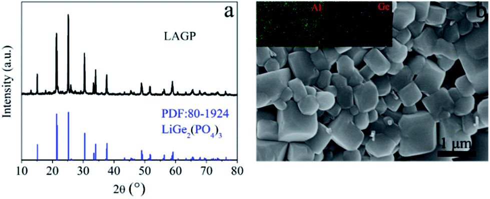 | ||
| Fig. 1 (a) XRD pattern of a LAGP particle (black line) and the reference sample LiGe2(PO4)3 (blue line), and (b) SEM image of a LAGP particle and the corresponding elemental mapping. | ||
2.2 Surface morphology and properties of the composite separator films
From the results shown in Fig. 2a, we can find the following facts: the Al2O3 layer coated on the surface of the PP separator film has no cracks; the dispersion of the particles is uniform; and the particle size is between several tens and hundreds of nanometres. Fig. 2c shows that the coating result of the LAGP particles is similar to that of the commercial Al2O3 particles, and the average particle size of LAGP is smaller. This indicates that the LAGP has been transformed to be smaller during the slurry processing. Both the dispersion of PVDF–HFP in aqueous media and the coating on the surface of the PP separator films are very successful. The formed PVDF–HFP particles have a uniform morphology with a particle size of 200–250 nm (Fig. 2d). The initial thickness of the PP separator film is 25 μm, and the thicknesses of the coated LAGP and PVDF–HFP layers are 2 and 3 μm, respectively. The areal density of the LAGP layer is 0.30 mg cm−2 and for the PVDF–HFP layer it is 0.40 mg cm−2.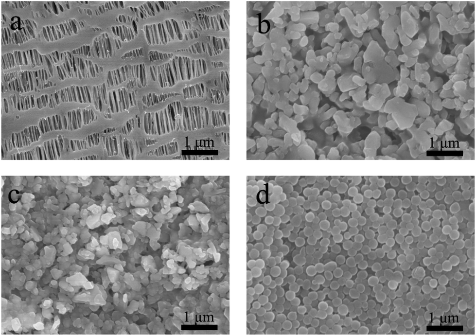 | ||
| Fig. 2 SEM images of (a) PP separator film, (b) Al2O3 layer on the surface of PP separator film, (c) LAGP layer on PP separator film, (d) PVDF–HFP layer on PP separator film. | ||
The electrolyte uptake of the separator films has a significant influence on the ionic conductivity and the cycle performance of the lithium ion battery. Generally, if the wettability of a separator film is improved, its electrolyte uptake is correspondingly increased, and the ionic conductivity is also increased. The wettability of the separator film is usually characterized by measuring the contact angle between the separator film and the electrolyte. The test results are shown in Fig. 3.
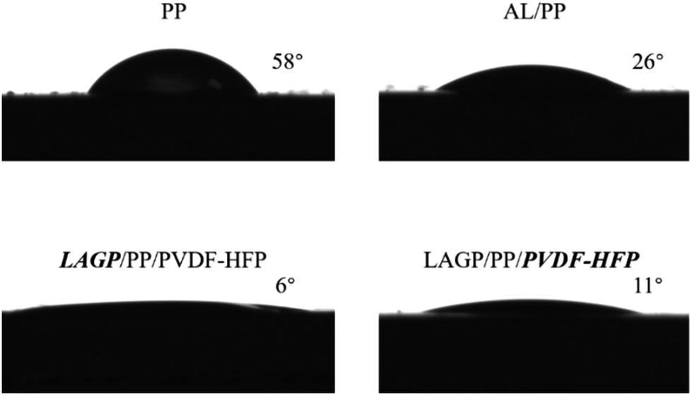 | ||
| Fig. 3 Electrolyte contact angles of the PP, AL/PP and LAGP/PP/PVDF–HFP separator films. | ||
The contact angle with the electrolyte is 58° for the PP separator film, 26° for the Al2O3 coating, 6° for the LAGP layer, and 11° for the PVDF–HFP layer. It is clear that LAGP has the best wettability for the electrolyte. The polyolefin separator has strong non-polar characteristics, which provide a poor wettability for the polar carbonate-based liquid electrolyte. PVDF–HFP not only exhibits a good wettability, but is also somewhat swelled by the electrolyte. This is advantageous for improving the performance of the separator film/electrode interface.
The electrolyte uptakes of several separator films are listed in Table 1. For a pristine PP separator film, it is 102%. The Al2O3 coating (AL) increases the electrolyte uptake of the AL/PP separator film up to 123%, while the LAGP/PP/PVDF–HFP separator film has an electrolyte uptake of 164%. This demonstrates the effect of improving the surface wettability on increasing the electrolyte uptake.
| Separator film code | Thickness (μm) | Contact angle (°) | Uptake (wt%) | Porosity (%) | 120 °C @ 2 h shrinkage (%) |
|---|---|---|---|---|---|
| PP | 25 | 58 | 102 | 45 | 5 |
| AL/PP | 27 | 26 | 123 | 43 | 0 |
| LAGP/PP/PVDF–HFP | 30 | 6 | 164 | 40 | 0 |
| LAGP/PP/PVDF–HFP | 30 | 11 | 164 | 40 | 0 |
Three different kinds of separator films were cut into 16 mm discs and sandwiched between two stainless steel plates and heated at 120 °C for 2 h. The shrinkage of the PP separator film was found to be 5%, while the size of the AL/PP separator film and the LAGP/PP/PVDF–HFP separator film did not change (shrinkage was 0%). This indicates that the introduction of an inorganic coating on the PP separator film can effectively improve the heat resistance of the film. The results of the differential scanning calorimetry (DSC) test (Fig. S1†) show that the melting temperatures of the PP, AL/PP and LAGP/PP/PVDF–HFP separator films are 166.3 °C, 168.6 °C and 170.6 °C, respectively. The thermogravimetric analysis (TGA) test (Fig. S2†) indicates that the 10% thermal weight loss of PP, AL/PP and LAGP/PP/PVDF–HFP separator films appears at 420 °C, 427 °C and 435 °C, respectively. The results of both tests indicate that the double-sided asymmetric coated separator film has the highest thermal stability.
2.3 Electrochemical window of composite separator films
The separator film must not undergo a redox reaction under the battery working conditions. As the energy density and voltage of the new generation of batteries increase, the separator film also faces the challenge of bearing a high voltage. The electrochemical window of 0–5 V is a new requirement for the separator film. As shown in Fig. 4a, the oxidation potentials of the PP separator film and AL/PP separator film are 4.4 and 4.8 V, respectively, while the oxidation potential of the LAGP/PP/PVDF–HFP separator film is 5.2 V. The LAGP/PP separator film exhibits an oxidation potential at 5.0 V, whereas the oxidation potential of PP/PVDF–HFP separator film is approximately 4.9 V in Fig. 4b. The improved electrochemical stability is caused by the formation of a gel polymer electrolyte (GPE), which consists of a LAGP/PP/PVDF–HFP separator film and a liquid electrolyte. With the gelation of the electrolyte, it becomes much more difficult to decompose.30 It can be concluded that the introduction of the LAGP layer and PVDF–HFP layer have a synergistic effect on improving the oxidation potential of the PP separator film. For LIBs, better electrochemical stability means a smaller polarization current at high voltage charging and discharging, thus resulting in a better cycle performance.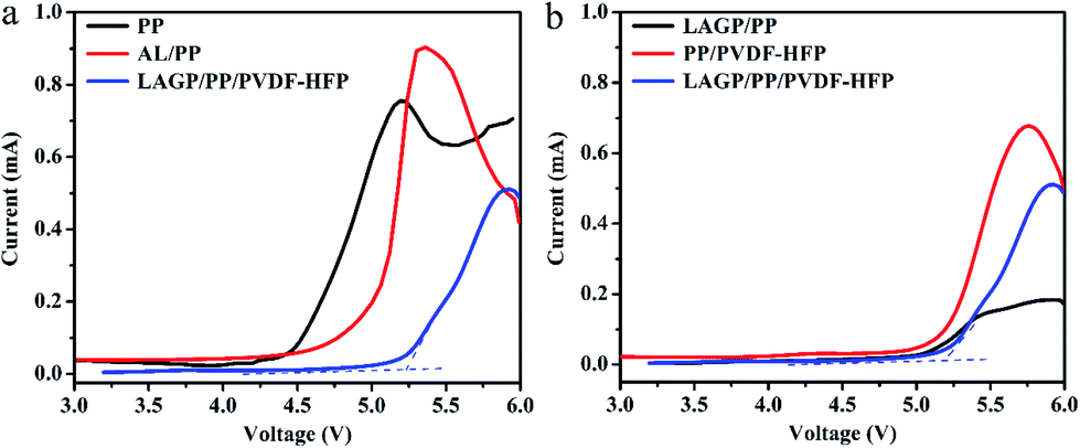 | ||
| Fig. 4 LSV curves of (a) PP, AL/PP, LAGP/PP/PVDF–HFP separator films and (b) LAGP/PP, PP/PVDF–HFP, LAGP/PP/PVDF–HFP separator films measured at the scan rate of 10 mV s−1. | ||
If a PP separator film is used in a high voltage battery of 4.8–5.0 V, the battery will not be able to complete the charging process and formation. When the PP separator film is coated with a ceramic coating, its suitability for high voltage batteries may be improved. However, we believe it is more desirable to use a new separator film with a broader electrochemical window.
2.4 Ionic conductivity of composite separator films
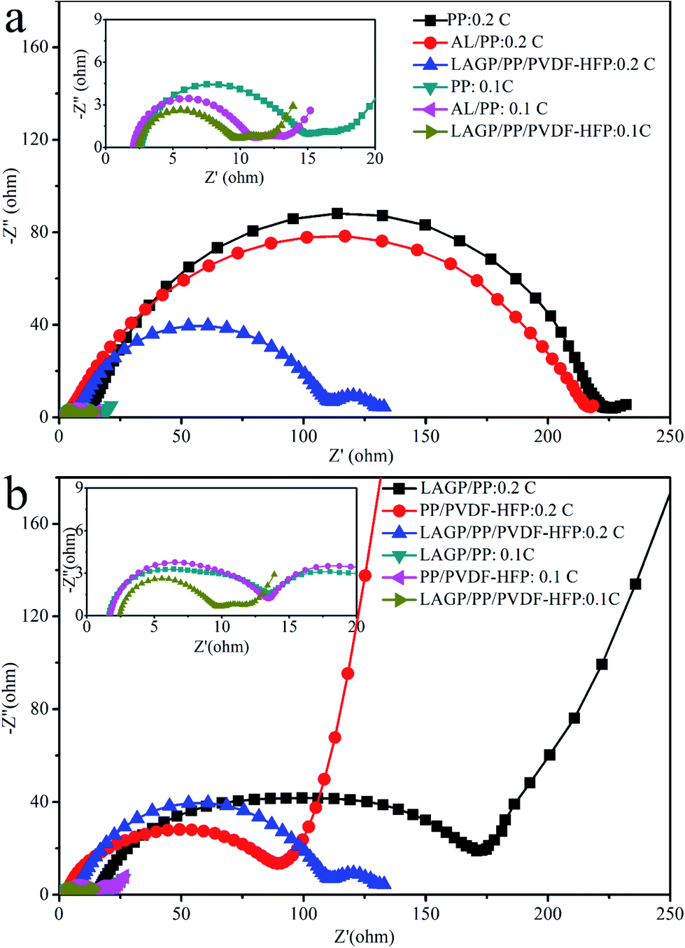
Ionic conductivity is one of the most important performance parameters of a separator film and is usually tested by the AC impedance method. If the AC impedance spectrum shows a straight line in the high frequency region, it indicates that the current carriers are ions, and the calculated conductivity is the ionic conductivity.31 In the high frequency region, the intersection value of the spectrum with the coordinate axis Z′ is the bulk resistance R of the separator film.The AC impedance spectra of the separator films are shown in Fig. 5. The ionic conductivity obtained from this measurement is 0.70 mS cm−1 for the PP film, 0.83 mS cm−1 for the AL/PP film, 0.73 mS cm−1 for the PP/PVDF–HFP film, 0.91 mS cm−1 for the LAGP/PP film and 1.06 mS cm−1 for the LAGP/PP/PVDF–HFP film. Compared with the PP separator film, the ionic conductivity of the AL/PP film is increased by 18.6%, and that of the LAGP/PP/PVDF–HFP separator film is increased by 51.4%. The ionic conductivity of the prepared LAGP film was 0.2 mS cm−1 (Fig. S4†). The introduction of the LAGP layer and PVDF–HFP layer have a synergistic effect on improving the ionic conductivity of the PP separator film. The bulk resistance and ionic conductivity of the films are listed in Table 2. The interface between the separator film and the electrodes directly affects the performance of a battery. The interface resistance is an important parameter used to characterize the electrode interface situation. We used the AC impedance method to detect the change in the interface resistance (Rint) of NCM811‖Li half cells with different separator films before and after cycling. For battery formation, the coin cells were first cycled at 0.1C three times, and the initial Rint was recorded. Then, after 100 cycles at 0.2C, the final Rint of coin cells was recorded. As shown in Fig. 6, the semi-cycle in the Nyquist plots represents Rint. After three cycles at 0.1C, the initial Rint was 12 Ω for the NCM811|PP|Li, 9 Ω for the NCM811|AL/PP|Li, 12 Ω for the NCM811|LAGP/PP|Li, 12 Ω for the NCM811|PP/PVDF–HFP|Li and 7 Ω for the NCM811|LAGP/PP/PVDF–HFP|Li. After 100 cycles at 0.2C, the final Rint increased to 223 Ω, 215 Ω, 155 Ω, 87 Ω and 109 Ω for the NCM811|PP|Li, NCM811|AL/PP|Li, NCM811|LAGP/PP|Li, NCM811|PP/PVDF–HFP|Li and NCM811|LAGP/PP/PVDF–HFP|Li, respectively. During the cycling process, the solid-electrolyte interphase (SEI) film gradually grows and the interface impedance keeps increasing.32 Obviously, the Rint of NCM811|PP/PVDF–HFP|Li is the lowest among the others, which proves that the introduction of the PVDF–HFP layer can significantly reduce the interface impendence of LIBs. Fig. S3† shows the variations of the impedance spectra of the NCM811|separator film|Li before and after 100 cycles at 0.2C. This illustrates that the introduction of a double-sided asymmetric coating, especially a PVDF–HFP layer, can effectively reduce the interface impedance of the battery. This effect will be reflected in the characteristics of the battery's rate, cycle and other characteristics.
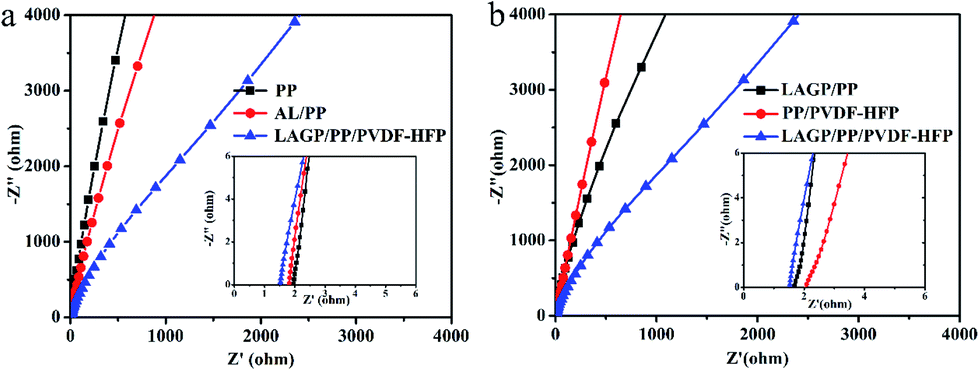 | ||
| Fig. 5 Nyquist plots of (a) PP, AL/PP and LAGP/PP/PVDF–HFP separator films and (b) LAGP/PP, PP/PVDF–HFP, LAGP/PP/PVDF–HFP separator films. | ||
| Separator film | Thickness (μm) | Bulk resistance (Ω) | Ionic conductivity (mS cm−1) |
|---|---|---|---|
| PP | 25 | 1.9 | 0.70 |
| AL/PP | 27 | 1.7 | 0.83 |
| PP/PVDF–HFP | 28 | 2.0 | 0.73 |
| LAGP/PP | 27 | 1.6 | 0.91 |
| LAGP/PP/PVDF–HFP | 30 | 1.5 | 1.06 |
 | ||
| Fig. 6 AC impedance spectra for the NCM811/Li half-cells before and after 100 cycles at 0.2C. | ||
2.5 Cycling and rate performances
Subsequent cycling tests further demonstrate the effect of interface impedance on the battery performance. Fig. 7a and b shows the cycling performance of the half-cells and full-cells with LAGP/PP, PP/PVDF–HFP and LAGP/PP/PVDF–HFP separator films at 0.2C. As indicated in Fig. 7a, the LAGP/PP/PVDF–HFP separator film showed an improved cycling performance compared with the LAGP/PP and PP/PVDF–HFP separator films. The LAGP/PP/PVDF–HFP separator film could steadily achieve a high discharge capacity of 143.5 mA h g−1 and retain 83.2% of the original capacity after 300 cycles. In contrast, the capacities of the half-cells with the LAGP/PP and PP/PVDF–HFP separator films were around 136.1 mA h g−1 (78.2%) and 129.4 mA h g−1 (77.6%), respectively. As shown in Fig. 8a and b, after 300 cycles (0.2C, 3.0–4.2 V, 25 °C), the discharge capacity of the cell using the AL/PP separator film and the PP separator film were 127.4 mA h g−1 (74.6%) and 128.3 mA h g−1 (71.9%), respectively. For the NCM811‖C full-cell, the capacity retentions were 143.4 mA h g−1 (81.0%), 135.4 mA h g−1 (76.9%), 110.7 mA h g−1 (65.5%), 131.8 mA h g−1 (79.4%) and 116.9 mA h g−1 (70.2%), using the LAGP/PP/PVDF–HFP, AL/PP, PP, LAGP/PP, PP/PVDF–HFP separator films, respectively. Fig. 8c and d shows the discharge curves of the NCM811|LAGP/PP/PVDF–HFP|Li and the NCM811|LAGP/PP/PVDF–HFP|C cells at different cycle times. The charging curves of the half and full cells with a LAGP/PP/PVDF–HFP separator film are shown in Fig. S5.† Obviously, the discharge capacity of the cell using the LAGP/PP/PVDF–HFP separator film is better than the other two kinds of cells using different separator films. After 200 cycles, the decrease in the capacity retention of the AL/PP separator film half-cell was significantly accelerated. This is due to its poor electrolyte retention and low electrochemical stability after the long cycle process.33 The LAGP/PP/PVDF–HFP separator film improves the cycling performance for both the full and half cells.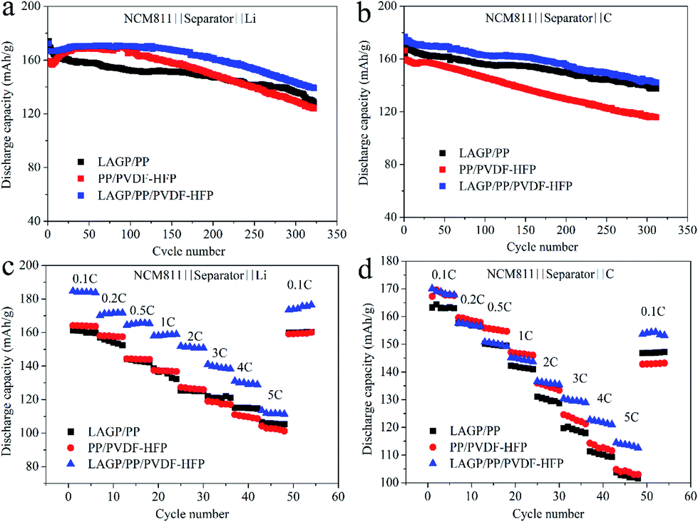 | ||
| Fig. 7 Charge–discharge cycling of (a) NCM811‖Li cells at 0.2C; (b) NCM811‖C cells at 0.2C and rate performance of (c) NCM811‖Li cells and (d) NCM811‖C cells with the LAGP/PP, PP/PVDF–HFP and LAGP/PP/PVDF–HFP separator films. | ||
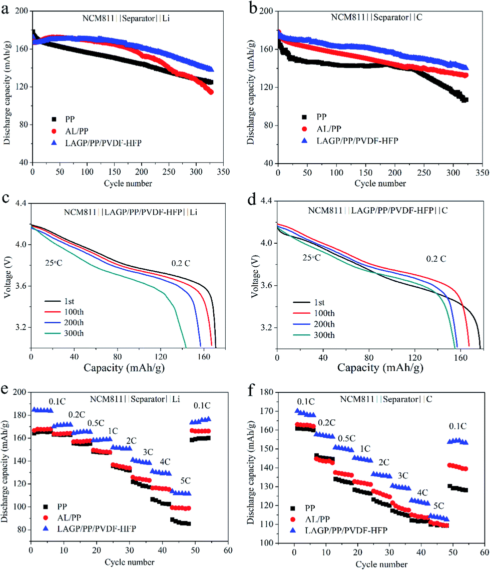 | ||
| Fig. 8 Charge–discharge cycling of (a) NCM811‖Li cells at 0.2C; and (b) NCM811‖C cells at 0.2C. Discharge profiles of (c) NCM811‖Li cell with LAGP/PP/PVDF–HFP separators film; and (d) NCM811‖C cell with LAGP/PP/PVDF–HFP separators film. Rate performance of (e) NCM811‖Li cells and (f) NCM811‖C cells. | ||
Rate capability has always been recognized as a key parameter to evaluate the performance of Li-ion batteries. To clearly elucidate the influence of the introduction of a double-sided asymmetric coating, the NCM811‖Li cells and NCM811‖C cells with pristine PP, AL/PP, LAGP/PP, PP/PVDF–HFP and LAGP/PP/PVDF–HFP separator films were assembled and the charge–discharge cycling test was performed at different C-rates varying from 0.2 to 5C.
The rate performance of the NCM811‖Li cells and NCM811‖C cells with PP, AL/PP, LAGP/PP/PVDF–HFP separator films is shown in Fig. 8e and f. At a rate of 0.1C, the discharge capacity of the cell applying the LAGP/PP/PVDF–HFP separator film was 184.0 mA h g−1, which was significantly higher than that of the PP separator film (164.0 mA h g−1) and the AL/PP separator film (166.0 mA h g−1). Under the conditions of 0.2, 0.5, 1, 2, 3, 4 and 5C, the capacity retention ratios of the cell using the LAGP/PP/PVDF–HFP separator film were notably higher than the cells using the other two separator films. At 5C, the capacity retention rates of the three cells were 111.4 mA h g−1 (60.5%), 85.3 mA h g−1 (52.0%) and 98.9 mA h g−1 (59.6%) respectively. When the rate returned from 5C to 0.1C, the discharge capacity of the cell using the LAGP/PP/PVDF–HFP separator film rose back to 96.0% of the discharge capacity at 0.1C. The full cells with the PP and AL/PP separator films showed discharge capacities of 161 and 163 mA h g−1 at a rate of 0.1C, respectively. Whereas it was 170 mA h g−1 when the LAGP/PP/PVDF–HFP separator film was used. Although the discharge capacity of all cells declined as the C-rate increased, the cells with the LAGP/PP/PVDF–HFP separator film showed the best performance (over 110 mA h g−1 at 5C). The discharge capacity of the cell with the LAGP/PP/PVDF–HFP separator film rose to 153.2 mA h g−1 when the discharge rate was set back to 0.1C, while the data were 128.2 and 139.5 mA h g−1 for cells with the PP and AL/PP separator films, respectively. From Fig. 7c and d, it is clear that the LAGP/PP/PVDF–HFP separator film achieves the best rate performance in both the half and full cells compared with the LAGP/PP and PP/PVDF–HFP separator film. Compared with the Al2O3 coating, the ability of LAGP to conduct Li+ is beneficial to the cell performance. Furthermore, the PVDF–HFP coating reduces the interfacial impedance. Based on the above described results, we believe that the LAGP/PP/PVDF–HFP separator film has an excellent performance and a remarkable application value.
2.6 Effect of asymmetric coated separator film on Li anode electrode
Based on the significant differences in the cycle and rate performance tests of cells using the PP, AL/PP and LAGP/PP/PVDF–HFP separator films, we proposed that the electrodes might have changed after a certain number of cycles, and the reason might be the application of different separator films.To prove this supposition, we disassembled the cells after 200 cycles (0.2C) and observed the morphology of the Li electrode using SEM. As shown in Fig. 9a, the Li anode of the cell with a PP separator had a rough, uneven surface. In Fig. 9b, there were many small holes on the surface of the Li anode. The reason for this is that the liquid electrolyte had side-reacted with the Li anode during the cycle process and was continuously consumed. There were some cracks on the surface of the lithium anode in contact with the PVDF–HFP coating of the composite separator film (Fig. 9c) owing to the uneven deposition of Li+ during the Li plating–stripping process.34 However, it still had a smooth surface after cycling to some extent. As shown in Fig. 9d–f, it is clear that the SEI formed in different cells consists of the same elements (C, O, F, P). The PVDF–HFP is stable to lithium and forms a uniform flow of lithium ions on the surface of the lithium anode. Moreover, the PVDF–HFP layer swells against the liquid electrolyte, and can effectively suppress the volume expansion of the lithium anode, which can improve the stability of the Li anode during the cycle process. Therefore, the introduction of a PVDF–HFP coating can effectively inhibit the formation and growth of the lithium dendrites.
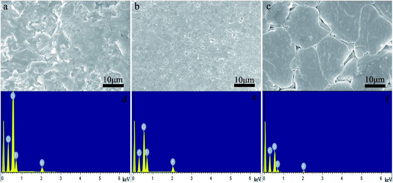 | ||
| Fig. 9 SEM image of the Li anode in NCM811‖Li cells after 200 cycles (a) with a PP separator film; (b) with an AL/PP separator film and (c) with a LAGP/PP/PVDF–HFP separator film. EDS image of the Li anode in NCM811‖Li cells after 200 cycles (d) with a PP separator film; (e) with an AL/PP separator film and (f) with a LAGP/PP/PVDF–HFP separator film. | ||
We compared the NCM811 battery data obtained in this study with the literature, and the data are listed in Table 3. In this work, the NCM811 battery assembled with the LAGP/PP/PVDF separator film was cycled at 0.2C 300 times with a discharge capacity retention of 83.2%, which was much higher than the average reported in the literature, and the cycle life was longer.
| Cycle number | Sources of NCM8111 | Mass loading (mg cm−2) | Charge–discharge voltage range | C-rate | Capacity retention | Separator film | Ref. |
|---|---|---|---|---|---|---|---|
| 100 | Synthesized | 2.1 | 3.0–4.3 V | 1C | 73.6% | PP/PE/PP | 35 |
| 100 | Synthesized | 2.0 | 3.0–4.4 V | 1C | 86.1% | PP | 36 |
| 150 | Synthesized | 4.4–4.6 | 2.8–4.3 V | 0.5C | 88.1% | — | 37 |
| 60 | Synthesized | 3.8 | 2.8–4.3 V | 0.2C | 80.0% | PP | 38 |
| 100 | Purchased | 9.1 | 3.0–4.2 V | 0.2C | 98.7% | LAGP/PP/PVDF–HFP | This work |
| 300 | Purchased | 9.1 | 3.0–4.2 V | 0.2C | 83.2% | LAGP/PP/PVDF–HFP | This work |
3 Experimental
3.1 Materials
Lithium carbonate (Li2CO3, A.R.), aluminum hydroxide (Al(OH)3, A.R.), ammonium dihydrogen phosphate (NH4H2PO4, A.R.), and N-methyl-2-pyrrolidone (NMP, A.R.) were purchased from Sinopharm Chemicals Reagent Co., Ltd. Cerium oxide (GeO2, 99.99%), plasticizer dibutyl phthalate (DBP), and coupling agent γ-glycidoxypropyltrimethoxysilane (KH560) were purchased from Sigma-Aldrich. The dispersant BYK111 and the wetting agent BYK307 were purchased from BYK Chemical. The aqueous dispersant BYK-LPC22136, the aqueous binder BYK-LPC22346, the aqueous defoamer BYK-1785, the aqueous wetting agent BYK-LPX20990, and the aqueous anti-settling agent LAPONITE®-RD were all purchased from BYK Chemical. Polyvinylidene fluoride (PVDF, HSV900) and polyvinylidene fluoride–hexafluoropropylene copolymer (PVDF–HFP, LBG) are products of Arkema. Alumina aqueous slurry BM-130 was purchased from Japan Region Group. LiNi0.8Co0.1Mn0.1O2, Super-P, graphite anode (mass loading: 6.0 mg cm−2) and lithium tablets were purchased from Shenzhen Kejing Zhida Co., Ltd.The high voltage electrolyte 1 M LiPF6 in a mixture of ethylene carbonate/dimethyl carbonate/diethyl carbonate (1![[thin space (1/6-em)]](https://www.rsc.org/images/entities/char_2009.gif) :1:1, w/w/w) was purchased from Beijing Chemical Reagent.
:1:1, w/w/w) was purchased from Beijing Chemical Reagent.
The planetary ball mill, BR40 is a product of Beijing Borui Xianke Equipment Co., the tube furnace model is GSL-1600X manufactured by Hefei Kejing Material Technology Co., and the coating equipment is a micro gravure coating machine designed by our institute and mainly includes unwinding, a coating head, a hot air drying oven and winding, tension control and rectification.
3.2 Preparation of asymmetrically coated LAGP/PP/PVDF–HFP composite separator film
:1. After filtration through a 150 mesh filter, a LAGP suspension was obtained. 28 g of PVDF were dissolved in 800 g of NMP with mechanical stirring for 3 h at room temperature. Subsequently, the LAGP suspension and PVDF solution were mixed and stirred for 12 h at 200 rpm. The mixture was filtered (150 mesh) to obtain a LAGP slurry with a viscosity of 50 mPa s.:1. After filtration (150 mesh), the ball-milled mixture was further treated with Bruker high-speed shearing and dispersing equipment at a speed of 10000 rpm to form a well-dispersed slurry. Followed by addition of 52.5 g of aqueous binder BYK-LPC22346 under stirring, an aqueous slurry of PVDF–HFP was prepared with a viscosity of 10 mPa s.3.3 Preparation of the AL/PP composite film
A commercial alumina aqueous slurry (BM-130) was coated onto the surface of a commercial PP separator film using a micro gravure coating machine under a drying temperature of 65 °C. The obtained single-side coated separator film was labelled as AL/PP.3.4 Battery assembly and measurement
LiNi0.8Co0.1Mn0.1O2 (84 wt%), Super-P (10 wt%) and PVDF (6 wt%) were mixed and dispersed in NMP for 12 h to form a slurry of solid content of 20%. Then, the slurry was blade-coated onto aluminium foil (16 μm). After drying (60 °C for 5 h and under vacuum for 12 h at 120 °C) and roller pressing (80 °C), a NCM811 cathode electrode was prepared with a thickness of 90 μm and a mass loading of 9.1 mg cm−2. The corresponding values for the purchased graphite anode were 52 μm and 6.0 mg cm−2, respectively.All kinds of separator films saturated with the liquid electrolyte were respectively applied to the NCM811 cathode and lithium metal anode to fabricate the CR2032 half-cells. Whereas full cells were fabricated when graphite was used as the anode instead of lithium. When the cells were assembled, the LAGP side of the LAGP/PP/PVDF–HFP separator film was opposed to the cathode, while the PVDF–HFP side was opposed to the anode. In the case of the AL/PP separator film used in the reference cells, the alumina side was in contact with the cathode. All full/half cells were assembled in the glovebox in which the content of O2 and H2O was less than 0.1 ppm.
The cycle performance and rate performance of the cells were tested between 3.0 to 4.2 V using a LAND battery cycler (CT2001A). The cycling performance was measured at 0.2C after being cycled at 0.1C three times for cell formation, and the rate capabilities were obtained at different current densities ranging from 0.1 to 5C for both charging and discharging. All of the electrochemical performance tests were carried out at room temperature excluding those indicated otherwise.
3.5 Characterization
The crystal structure of the LAGP powder was characterized using X-ray powder diffraction (XRD, Bruker's D8 focus) using CuKα radiation with a scan range of 10–80°. The surface morphology of the PP, AL/PP, LAGP/PP/PVDF–HFP separator films and LAGP powder were observed with a field emission electron microscope (FESEM, S-4800, Hitachi, Japan). After hundreds of charge–discharge cycles, the cells were disassembled in a glove box and the lithium anode was taken out. The Li anode was washed with dimethyl carbonate (DMC) and ethanol three times, respectively. Then, the samples were transferred from the glove box to the injection chamber of the FESEM (S-4800, Hitachi) for observation under the protection of an inert atmosphere.The electrolyte uptake (U) was obtained by immersing the separator films in the liquid electrolyte until they were saturated, and then the separator films were removed. The retained electrolyte solution on the surface was wiped off with filter papers. The electrolyte uptake was calculated using eqn (1).
 | (1) |
In which M0 and M represent the weight of the dry and wetted separator film, respectively. The contact angles of the three separator films to the electrolyte were tested using a contact angle tester (Dataphysics OCA-20 Apparatus) at room temperature.
The heat resistance was characterized by measuring the ratio of shrinkage when heated (120 °C, 2 h), the melting point, and the thermal decomposition temperature of the separator films. The melting point was measured using a differential scanning calorimeter (Mettler, with a heating rate of 10 °C min−1 from 50 to 250 °C in an N2 atmosphere), and the thermal decomposition temperature (Td) was measured using a thermogravimetric analyzer (TGA, TQ-50, TA with a heating rate of 10 °C min−1 from 25 to 700 °C in an N2 atmosphere).
The ionic conductivities of the composite separator films were measured using an electrochemical workstation system (Zennium 6, Germany) with an AC amplitude of 5 mV in the frequency range of 0.1 Hz to 1 MHz. The composite separator film was sandwiched between two stainless-steel blocking electrodes to form the test cells. The separator films were saturated with electrolyte before use. The ion conductivity (δ) can be calculated using eqn (2):39,40
 | (2) |
4 Conclusions
We prepared a LAGP/PP/PVDF–HFP double-sided asymmetric composite separator film using roll-to-roll micro gravure coating technology. The separator film has a good thermal stability and wettability. The composite separator film has an ionic conductivity of 1.06 mS cm−1 (room temperature) and an electrochemical stability window up to 5.2 V. The wide electrochemical window allows this type of separator film to be used in high voltage (∼5 V) battery systems. The composite separator film can effectively reduce the interface impedance of the battery and has a superior interfacial compatibility with electrodes, which improves the stability of the interface. The capacity retention of the full-cell after 0.2C cycles of 300 cycles is 81.0%. The initial discharge capacity of the NCM half-cell assembled with the asymmetric composite separator film is 172.5 mA h g−1 with a capacity retention of 83.2% after 300 cycles at 0.2C. After 200 cycles, the surface of the lithium anode is smooth, and the formation of lithium dendrites is suppressed. In short, the composite separator film constructed with LAGP, PP and PVDF–HFP demonstrates an excellent performance, and can be used as the separator film in the next generation of lithium ion batteries.Conflicts of interest
There are no conflicts to declare.Acknowledgements
We are grateful for the financial support given by the National Key R&D Program “New Energy Vehicles” Pilot Project (2016YFB0100105) and the Chinese Academy of Sciences Strategic Pilot Science and Technology Special Project XDA09010105.References
- L. Suo, Y. S. Hu, H. Li, M. Armand and L. Chen, A new class of Solvent-in-Salt electrolyte for high-energy rechargeable metallic lithium batteries, Nat. Commun., 2013, 4, 1481 CrossRef PubMed.
- W. Wang, X. Yue, J. Meng, J. Wang, X. Wang, H. Chen, D. Shi, J. Fu, Y. Zhou, J. Chenand and Z. Fu, Lithium phosphorus oxynitride as an efficient protective layer on lithium metal anodes for advanced lithium-sulfur batteries, Energy Storage Materials, 2019, 18, 414–422 CrossRef.
- D. Xu, Z. L. Wang, J. J. Xu, L. L. Zhang, L. M. Wang and X. B. Zhang, A stable sulfone based electrolyte for high performance rechargeable Li-O2 batteries, Chem. Commun., 2012, 48, 11674–11676 RSC.
- D. Xu, Z. L. Wang, J. J. Xu, L. L. Zhang and X. B. Zhang, Novel DMSO-based electrolyte for high performance rechargeable Li-O2 batteries, Chem. Commun., 2012, 48, 6948–6950 RSC.
- J. J. Xu, Z. L. Wang, D. Xu, F. Z. Meng and X. B. Zhang, 3D ordered macroporous LaFeO3 as efficient electrocatalyst for Li-O2 batteries with enhanced rate capability and cyclic performance, Energy Environ. Sci., 2014, 7, 2213–2219 RSC.
- R. H. Zhang, T. S. Zhao, H. R. Jiang, M. C. Wu and L. Zeng, V2O5-NiO composite nanowires: A novel and highly efficient carbon-free electrode for non-aqueous Li-air batteries operated in ambient air, J. Power Sources, 2019, 409, 76–85 CrossRef CAS.
- J. B. Goodenough and K. S. Park, The Li-ion rechargeable battery: a perspective, J. Am. Chem. Soc., 2013, 135, 1167–1176 CrossRef CAS PubMed.
- H. Lee, M. Yanilmaz, O. Toprakci, K. Fu and X. Zhang, A review of recent developments in membrane separator films for rechargeable lithium-ion batteries, Energy Environ. Sci., 2014, 7, 3857–3886 RSC.
- J. Liu, J. G. Zhang, Z. Yang, J. P. Lemmon, C. Imhoff, G. L. Graff, L. Li, J. Hu, C. Wang, J. Xiao, G. Xia, V. V. Viswanathan, S. Baskaran, V. Sprenkle, X. Li, Y. Shao and B. Schwenzer, Materials science and materials chemistry for large scale electrochemical energy storage: From transportation to electrical grid, Adv. Funct. Mater., 2013, 23, 929–946 CrossRef CAS.
- V. Etacheri, R. Marom, R. Elazari, G. Salitra and D. Aurbach, Challenges in the development of advanced Li-ion batteries: a review, Energy Environ. Sci., 2011, 4, 3243–3262 RSC.
- J. Peng, C. X. Zu and H. Li, Fundamental scientific aspects of lithium batteries (I) - Thermodynamic calculations of theoretical energy densities of chemical energy storage systems, Energy Storage Sci. Technol., 2011, 2(1), 55–63 Search PubMed.
- H. Li, Practical evaluation of Li-ion batteries, Joule, 2019, 3, 911–914 CrossRef CAS.
- CAS Research Group on High Energy Density Lithium Batteries for EV, Progress on high energy density lithium batteries by CAS battery research group, Energy Storage Sci. Technol., 2016, 5(2), 177–180 Search PubMed.
- C. Wang and D. Y. Wu, LIB separator films and the recent technical progress, Energy Storage Sci. Technol., 2016, 5(2), 120–128 CAS.
- M. H. Ryou, Y. M. Lee, J. K. Park and J. W. Choi, Mussel-inspired polydopamine-treated polyethylene separator films for high-power Li-ion batteries, Adv. Mater., 2011, 23, 3066–3070 CrossRef CAS PubMed.
- S. Hu, S. Lin, Y. Tu, J. Hu, Y. Wu, G. Liu, F. Li, F. Yu and T. Jiang, Novel aramid nanofiber-coated polypropylene separator films for lithium ion batteries, J. Mater. Chem. A, 2016, 4, 3513–3526 RSC.
- L. F. Fang, J. L. Shi, J. H. Jiang, H. Li, B. K. Zhu and L. P. Zhu, Improving the wettability and thermal resistance of polypropylene separators with a thin inorganic–organic hybrid layer stabilized by polydopamine for lithium ion batteries, RSC Adv., 2014, 4, 22501–22508 RSC.
- Z. Wang, H. Xiang, L. Wang, R. Xia, S. Nie, C. Chen and H. Wang, A paper-supported inorganic composite separator film for high-safety lithium-ion batteries, J. Membr. Sci., 2018, 553, 10–16 CrossRef CAS.
- M. Chi, L. Shi, Z. Wang, J. Zhu, X. Mao, Y. Zhao, M. Zhang, L. Sun and S. Yuan, Excellent rate capability and cycle life of Li metal batteries with ZrO2/POSS multilayer-assembled PE separator films, Nano Energy, 2016, 28, 1–11 CrossRef CAS.
- H. Chen, Q. Lin, Q. Xu, Y. Yang, Z. Shao and Y. Wang, Plasma activation and atomic layer deposition of TiO2 on polypropylene membranes for improved performances of lithium-ion batteries, J. Membr. Sci., 2014, 458, 217–224 CrossRef CAS.
- Y. S. Jung, A. S. Cavanagh, L. Gedvilas, N. E. Widjonarko, I. D. Scott, S. H. Lee, G. H. Kim, S. M. George and A. C. Dillon, Improved functionality of lithium-ion batteries enabled by atomic layer deposition on the porous microstructure of polymer separator films and coating electrodes, Adv. Energy Mater., 2012, 2, 1022–1027 CrossRef CAS.
- L. Fan, S. Wei, S. Li, Q. Li and Y. Lu, Recent progress of the solid-state electrolytes for high-energy metal-based batteries, Adv. Energy Mater., 2018, 8, 1702657 CrossRef.
- P. Hartmann, T. Leichtweiss, M. R. Busche, M. Schneider, M. Reich, J. Sann, P. Adelhelm and J. Janek, Degradation of NASICON-type materials in contact with lithium metal: formation of mixed conducting interphases (MCI) on solid electrolytes, J. Phys. Chem. C, 2013, 117, 21064–21074 CrossRef CAS.
- J. Shi, Y. Xia, S. Han, L. Fang, M. Pan, X. Xu and Z. Liu, Lithium ion conductive Li1.5Al0.5Ge1.5(PO4)3 based inorganic–organic composite separator film with enhanced thermal stability and excellent electrochemical performances in 5 V lithium ion batteries, J. Power Sources, 2015, 273, 389–395 CrossRef CAS.
- B. Yan, Y. Zhu, F. Pan, J. Liu and L. Lu, Li1.5Al0.5Ge1.5(PO4)3 Li-ion conductor prepared by melt-quench and low temperature pressing, Solid State Ionics, 2015, 278, 65–68 CrossRef CAS.
- M. Kotobuki, K. Hoshina and K. Kanamura, Electrochemical properties of thin TiO2 electrode on Li1+xAlxGe2−x(PO4)3 solid electrolyte, Solid State Ionics, 2011, 198, 22–25 CrossRef CAS.
- X. Xu, Z. Wen, X. Wu, X. Yang and Z. Gu, Lithium ion-conducting glass-ceramics of Li1.5Al0.5Ge1.5(PO4)3-xLi2O (x = 0.0-0.20) with good electrical and electrochemical properties, J. Am. Ceram. Soc., 2007, 90, 2802–2806 CrossRef CAS.
- L. Hagmanand and P. Kierkegaard, The crystal structure of NaMe2IV(PO4)3; MeIV=Ge, Ti, Zr, Acta Chem. Scand., 1968, 22(6), 1822–1832 CrossRef.
- S. Zhang, S. Wang, S. Ling, J. Gao, J. Yang, R. Xiao, H. Li and L. Chen, Fundamental scientific aspects of lithium ion batteries(X)—All-solid-state lithium-ion batteries, Energy Storage Sci. Technol., 2014, 3(4), 376–394 Search PubMed.
- X. Zuo, J. Wu, X. Ma, X. Deng, J. Cai, Q. Chen, J. Liu and J. Nan, A poly(vinylidene fluoride)/ethyl cellulose and amino-functionalized nano-SiO2 composite coated separator film for 5 V high-voltage lithium-ion batteries with enhanced performance, J. Power Sources, 2018, 407, 44–52 CrossRef CAS.
- Y. Zhu, F. Wang, L. Liu, S. Xiao, Z. Chang and Y. Wu, Composite of a nonwoven fabric with poly(vinylidene fluoride) as a gel membrane of high safety for lithium ion battery, Energy Environ. Sci., 2013, 6, 618–624 RSC.
- M. Yanilmaz, Y. Lu, M. Dirican, K. Fu and X. Zhang, Nanoparticle-on-nanofiber hybrid membrane separator films for lithium-ion batteries via combining electrospraying and electrospinning techniques, J. Membr. Sci., 2014, 456, 57–65 CrossRef CAS.
- D. Li, D. Qin, F. Nie, L. Wen and L. Xue, Enhancement of electrochemical performance of lithium-ion battery by single-ion conducting polymer addition in ceramic-coated separator film, J. Mater. Sci., 2018, 53, 11038–11049 CrossRef CAS.
- Q. Li, B. Quan, W. Li, J. Lu, J. Zheng, X. Yu, J. Li and H. Li, Electro-plating and stripping behavior on lithium metal electrode with ordered three-dimensional structure, Nano Energy, 2018, 45, 463–470 CrossRef CAS.
- S. J. Do, P. Santhoshkumar, S. H. Kang, K. Prasanna, Y. N. Jo and C. W. Lee, Al-Doped Li[Ni0.78Co0.1Mn0.1Al0.02]O2 for high performance of lithium ion batteries, Ceram. Int., 2019, 45, 6972–6977 CrossRef CAS.
- J. Zhu, Y. Li, L. Xue, Y. Chen, T. Lei, S. Deng and G. Cao, Enhanced electrochemical performance of Li3PO4 modified Li[Ni0.8Co0.1Mn0.1]O2 cathode material via lithium-reactive coating, J. Alloys Compd., 2019, 773, 112–120 CrossRef CAS.
- Q. Fan, S. Yang, J. Liu, H. Liu, K. Lin, R. Liu, C. Hong, L. Liu, Y. Chen, K. An, P. Liu, Z. Shi and Y. Yang, Mixed-conducting interlayer boosting the electrochemical performance of Ni-rich layered oxide cathode materials for lithium ion batteries, J. Power Sources, 2019, 421, 91–99 CrossRef CAS.
- S. Gao, X. Zhan and Y. T. Cheng, Structural, electrochemical and Li-ion transport properties of Zr-modified LiNi0.8Co0.1Mn0.1O2 positive electrode materials for Li-ion batteries, J. Power Sources, 2019, 410–411, 45–52 CrossRef CAS.
- Y. Zhang, Z. Wang, H. Xiang, P. Shi and H. Wang, A thin inorganic composite separator film for lithium-ion batteries, J. Membr. Sci., 2016, 509, 19–26 CrossRef CAS.
- J. Dai, C. Shi, C. Li, X. Shen, L. Peng, D. Wu, D. Sun, P. Zhang and J. Zhao, A rational design of separator film with substantially enhanced thermal features for lithium-ion batteries by the polydopamine-ceramic composite modification of polyolefin membranes, Energy Environ. Sci., 2016, 9, 3252–3261 RSC.
Footnote |
| † Electronic supplementary information (ESI) available. See DOI: 10.1039/c9ra09200e |
| This journal is © The Royal Society of Chemistry 2019 |