
Impact of bonding at multi-layer graphene/metal Interfaces on thermal boundary conductance
Liang Chena,
Zhen Huangb and
Satish Kumar*a
aG. W. Woodruff School of Mechanical Engineering, Georgia Institute of Technology, Atlanta, GA, USA. E-mail: satish.kumar@me.gatech.edu
bDell Inc., Austin, TX, USA
First published on 24th July 2014
Abstract
We use density functional theory and the atomistic Green's function method (AGF) to study the effect of bonding on phonon transmission and thermal boundary conductance (TBC) at the interface of metals (Au, Cu, and Ti) and single layer graphene (SLG)/multi-layer graphene (MLG). Our analysis shows that the TBC across Ti/SLG/Ti interfaces (∼500 MW m−2 K−1) is significantly larger than the TBC across Cu/SLG/Cu (∼10 MW m−2 K−1) and Au/SLG/Au (∼7 MW m−2 K−1) interfaces. However, the TBC across Ti/MLG/Ti (∼40 MW m−2 K−1) is an order of magnitude lower compared to TBC at the Ti/SLG/Ti interface, whereas the TBC at Cu/MLG/Cu and Au/MLG/Au interfaces are similar to those of Cu/SLG/Cu and Au/SLG/Au, respectively. We find that this substantial decrease in TBC at the Ti/MLG/Ti interface is a result of phonon mismatch between the graphene layer bonded to Ti and the non-bonded graphene layers. The effect of number of graphene layers on TBC at Cu/MLG/Cu and Au/MLG/Au interfaces is relatively insignificant because of the weak interactions at these metal/graphene interfaces. It was observed that the moderate attenuation of Ti/C bonding strength can enhance the phonon coupling between the graphene layers bonded to Ti and non-bonded graphene layers, and can increase the TBC across Ti/MLG/Ti by ∼100%. This impact of interfacial bonding strength on TBC at metal/MLG interfaces, predicted by AGF calculations, is further confirmed by non-equilibrium molecular dynamics simulations which show the transition of thermal transport mechanism from metal/graphene dominated resistance to graphene/graphene dominated resistance as the metal/graphene bonding strength increases in the metal/MLG/metal structure.
Introduction
The extraordinary carrier mobility, thermal conductivity1 and mechanical properties2 of graphene have intrigued researchers, who have pursued research in graphene nano-electronic devices such as field-effect transistors3 and optoelectronic devices.4 The single layer pristine graphene sheet has very low bandgap which makes it unsuitable for logic applications.5 However, the bandgap of multi-layer graphene (MLG) can be tuned by controlling the stacking order while maintaining high carrier mobility.6,7 The recent progress in fabrication and structure-manipulation techniques has made MLG a promising material for nano-electronic devices.8–10 MLG can have considerable contact with metal electrodes in its electronic devices, which can also be an important pathway for heat dissipation.11,12 Many previous studies have measured thermal boundary conductance (TBC) between graphene/graphite and various metals such as Al, Au, Cu, Ti, and so on.13–16 A very low TBC has been reported for some metals such as 7–20 MW m−2 K−1 for graphene/Au interfaces.14 The low TBC can hinder the effective heat removal from the nano-electronic devices leading to degradation of performance and reliability.11 It is crucial to estimate the TBC and decipher the phonon transport mechanism at various graphene/metal interfaces to further engineer these interfaces for effective thermal management and enhanced performance.The interfacial chemistry can significantly affect the strength of interaction as well as the TBC at the graphene/metal contacts.17 Recent studies have shown that the TBC across graphene/metal interfaces depends on multiple factors such as interfacial structure,25,26 bonding,18,19 contaminants and defects,14,16 and so on.20,21 Depending on their type of bonding, graphene/metal interfaces can be classified into two types: a physisorption interface (e.g., Al, Ag, Au, Cu, and Pt) formed by charge transfer and a chemisorption interface (e.g., Co, Ni, Pd, and Ti) formed by orbital hybridization.6,22,23 Several studies13–16 have measured TBC at highly oriented pyrolitic graphite (HOPG) and metal interfaces. The TBC at physisorption HOPG/metal interfaces (e.g., Au, Al, and Cu) has been reported in the range of 7 to 60 MW m−2 K−1 around room temperature, whereas the TBC at chemisorption interfaces (e.g., HOPG/Ti) has been reported to be as high as 120 MW m−2 K−1. These measurements at the HOPG/metal interfaces are often used as approximations of TBC at the graphene/metal interfaces. However, the impact of interfacial bonding on TBC across the MLG/metal interface remains unclear.
Thermal properties of MLG in electronic devices can be very different from HOPG as (i) MLG may have much smaller cross-plane dimension;24–26 and (ii) interaction with the surroundings can significantly change the phonon properties of MLG.27–30 An important query, which has been a topic of investigation in some recent studies,19,25,31–37 is how the number of graphene layers (n) in a MLG affects its thermal conductivity and TBC across its interfaces. The thickness of MLG is generally much smaller than the phonon mean free path of HOPG in a cross-plane direction; therefore boundary/interface scattering of phonons is dominant for thermal transport across MLG. It has been demonstrated that the cross-plane thermal conductivity of MLG is smaller than that of HOPG and has a strong dependence on n as the phonon mean free path in MLG is limited by its thickness.33,35 However, both experiments38 and simulations19,31,32 have shown that increasing n from 3 to 10 only slightly reduces or has no effect on the TBC across the embedded MLG. When n is less than or equal to three (i.e., single, bilayer or trilayer embedded graphenes), the effect of n on TBC may depend on the contact materials.19,31,32 For SiO2/graphene interfaces, increasing the graphene layers from a single one to a few layers slightly reduces32,38 or does not change19 the TBC. The effect of n on TBC at metal/graphene interfaces becomes complicated because of the different interfacial chemistry at different metal interfaces.
Chang et al.31 and Shen et al.19 performed non-equilibrium molecular dynamics (NEMD) simulations to study the TBC across Cu/MLG/Cu structures. Both studies have shown a larger reduction in TBC from Cu/SLG/Cu to Cu/MLG/Cu. In their NEMD simulations, the Lennard-Jones (L-J) potential model is used to describe the Cu/graphene interactions, which have large interatomic force constants (IFCs) for Cu–C interactions.19 But density functional theory (DFT) calculations have shown weak Cu/graphene interactions.21,22,39 These different descriptions of the Cu/graphene interaction can lead to very different trends and contradictory results for the TBC dependence on n. A first principles study is necessary to determine the effect of bonding strength at the interface and accurately decipher the effect of n on TBC across different metal/MLG/metal structures. If a graphene layer of MLG is chemically bonded to the metallic contact (e.g., graphene/Ti bonding), the phonon states of this graphene layer can be significantly changed by the chemical bonds whereas the other graphene layers of MLG have a weak interaction with the contacts and remain in a pristine state.40 Therefore, a large mismatch in phonon density of the states between the first graphene layer (∼bonded to the metal) and the adjacent graphene layers can reduce the phonon coupling between these graphene layers as well as the cross-plane thermal conductance of the MLG. Metal/graphene bonding strength has a different impact on phonon coupling at metal/graphene and graphene/graphene interfaces. Strong bonding can increase phonon coupling between first layer of MLG and metal, but it creates phonon mismatch and reduces the phonon coupling between the graphene layers in the MLG. The interplay of these two mechanisms and their corresponding effects on thermal transport across the MLG/metal interfaces are still not well understood.
In order to elucidate the impact of interfacial bonding on thermal transport between MLG and different metals, we performed first principle DFT and atomistic Green's function method (AGF) based calculations to investigate phonon transmission and TBC at metal/SLG/metal (Fig. 1(a)) and metal/MLG/metal (Fig. 1(b)) interfaces. We consider three different materials: Cu and Au for the weak physisorption bonding and Ti for strong chemisorption bonding. We find that the results for TBCs of Cu/SLG/Cu and Cu/MLG/Cu are comparable, which is in contrast to previous studies using MD simulations.19,31 We observe a similar trend for TBC at Au/MLG/Au and Au/MLG/Au interfaces. This indicates that the graphene/metal interface dominates the heat transfer at physisorption interfaces between MLG and metal. On the other hand for Ti/MLG/Ti structure, Ti–C interactions significantly change the phonon density of states (DOS) of the graphene layer bonded to Ti and reduce its phonon coupling with the adjacent graphene layer. As a result, thermal contact resistance (TCR) between these graphene layers dominates the heat transfer across Ti/MLG/Ti interfaces, and results in much smaller TBC than the Ti/SLG/Ti interfaces. We investigate how the bonding strength changes the graphene/metal and graphene/graphene phonon coupling by scaling graphene/metal interatomic force constants. We demonstrate that because of the trade-off between graphene/Ti TCR and graphene/graphene TCR, an appropriate attenuation of Ti–C bonding strength across the Ti/MLG/Ti interfaces can increase the TBC rather than decreasing it. The findings in this study will provide insights to understand the experimental measurements of TBC at graphene/metal interfaces and to engineer these interfaces to enhance the TBC.
 | ||
| Fig. 1 Schematic of (a) metal/SLG/metal system and (b) metal/MLG/metal system for the AGF calculations. Multi-layer graphene consists of a single layer of graphene (SLG) with AB-stacking. The SLG and MLG are considered as the devices (D) which are sandwiched between two metal contacts: left contact (LC) and right contact (RC). The regions beyond LC or RC are defined as the left contact bulk (LCB) and right contact bulk (RCB), which do not interact with the device region. Views in the x–y plane and the x–z plane of a unit cell for (c) SLG/Cu, (d) SLG/Au and (e) SLG/Ti structures. These structures have been optimized using DFT calculations to estimate the equilibrium distance between metal and graphene. Only four layers of metal atoms are shown. | ||
Models and methodology
In this study, AGF calculations were performed to determine the phonon transmission function at MLG/metal interfaces, and the TBC is then calculated using the Landauer formula.41–43 In AGF calculations, the lattice interactions at interfaces with predefined nano-structures can be described by second order IFCs neglecting anharmonic effects. In the absence of accurate empirical interatomic potential models for graphene/metal interactions, we optimized graphene/metal structures and derived the IFCs using DFT calculations.44 Fig. 1(a) and (b) show the structures of SLG/metal and MLG/metal interfaces considered in the AGF calculations. The SLG or MLG is sandwiched between two metal contacts to form the symmetrical metal/SLG/metal or metal/MLG/metal structures. The phonon transmission and TBC across the device (SLG or MLG) region involves two identical interfaces, and the TBC values across the single interface can be obtained by multiplying by 2. A top view, in the x–y plane, of the graphene/metal interfaces are shown in Fig. 1(c)–(e) for Cu, Au and Ti, respectively. Cu (111), Au (111), and Ti (0001) surfaces are cleaved to make contact with the graphene sheets; these surfaces are perpendicular to the z axis (see Fig. 1). In order to form periodic lattices in the x and y directions, a graphene/Cu unit cell consists of one graphene unit cell whereas the graphene/Au and graphene/Ti unit cells consist of four graphene unit cells. Finally, we perform NEMD simulations to further validate the results of the AGF calculations and examine the anharmonic effects.45Density functional theory calculations
We used the Vienna ab initio simulation package (VASP) for the DFT calculations.44 Plane wave basis sets with a kinetic energy cut-off of 400 eV are used in the projector augmented-wave (PAW) method.46 We used 32 × 32 × 1 k-point grids for Cu/SLG system and 21 × 21 × 1 k-point grids for Au/SLG and Ti/SLG structures. The optimized in-plane lattice constant a of graphene is 2.45 Å, and the metal lattices are adjusted to match the graphene lattices. With a = 2.45 Å, the spacing, d, between the graphene and metal surfaces were further optimized using DFT calculations. The optimized spacings are 3.23 Å, 3.37 Å, and 2.15 Å for the Cu, Au, and Ti interfaces with graphene, respectively, as shown in Fig. 1(c)–(e), which are consistent with results obtained with previous DFT studies.22,47 The graphene/Ti spacing is quite close to the Ti–C bonding length (2.13 Å) in a TiC crystal which indicates the chemisorption bonding for the two Ti–C pairs at the graphene/Ti interface in a unit cell as shown in Fig. 1(e). The second order IFCs for C–C, metal–metal, and metal–C atom pairs are obtained by DFT calculations using a 5 × 5 supercell for the Cu/SLG system and a 3 × 3 supercell for the Au/SLG and Ti/SLG system.48 We used 3 × 3 × 1 k-point grids to sample the Brillouin zone of this supercell, and displace each atom in two directions: in plane and orthogonal to the graphene plane. The displacement magnitudes were ±0.03 Å in both cases. Using the IFCs obtained from the DFT simulations, we constructed the harmonic matrices which describe the interatomic interactions in the AGF calculations.42Atomistic Green's function calculations
We obtained the transmission function from AGF calculations, and then used the Landauer formula to calculate the TBC.43
 | (1) |
![[k with combining right harpoon above (vector)]](https://www.rsc.org/images/entities/i_char_006b_20d1.gif) ‖) is the transmission function at frequency ω and transverse k-point ‖ = (kx,ky).43
‖) is the transmission function at frequency ω and transverse k-point ‖ = (kx,ky).43|
Ξ(ω,‖) = Trace[ΓLGLD,RDΓRG†LD,RD]
| (2) |
‖ can be used to include the phonons of all wavelengths.41,43 With the plane-wave formulation, each layer can be represented by one unit cell (Fig. 1(c)) and the sampling in the Brillouin zone is performed with a ‖ mesh of 200 × 200. The Monkhorst and Pack scheme49 was used to discretize the Brillouin zone. The details about the calculation of transmission function using the AGF method can be found in the ref. 41–43.
Non-equilibrium molecular dynamics simulations
The NEMD simulations were performed on the Cu/trilayer graphene (3LG)/Cu structures using Lammps molecular dynamics simulation package.50 We used the optimized Tersoff potential51 and the embedded-atom method (EAM) potential52 to describe the C–C interactions and the Cu–Cu interactions, respectively. We modelled the interaction between the C–Cu atoms at the interface using the Lennard-Jones (L-J) potential:| Vij(r) = 4χεij[(σij/r)12 − (σij/r)6] | (3) |
![[thin space (1/6-em)]](https://www.rsc.org/images/entities/char_2009.gif) 392. Each system is first equilibrated in NVT [constant number (N), volume (V) and temperature (T)] at 300 K for 0.5 ns and in NVE [constant number (N), volume (V) and energy (E)] for another 0.5 ns. Then a heating rate of ±45 nW is applied at the heating/cooling bath which consists of 3519 atoms. Each system is simulated for 5 ns to first obtain a steady state, and then the data are sampled for an additional 5 ns which is used for the estimation of temperature profiles.
392. Each system is first equilibrated in NVT [constant number (N), volume (V) and temperature (T)] at 300 K for 0.5 ns and in NVE [constant number (N), volume (V) and energy (E)] for another 0.5 ns. Then a heating rate of ±45 nW is applied at the heating/cooling bath which consists of 3519 atoms. Each system is simulated for 5 ns to first obtain a steady state, and then the data are sampled for an additional 5 ns which is used for the estimation of temperature profiles.
Results and discussions
SLG and metal substrates interactions
The bonding between the graphene and metal atoms at the interface can be illustrated by the distribution of electron localization function (ELF) as shown in Fig. 2. ELF describes chemical bonds by the probability of finding another same-spin electron in the neighborhood of a reference electron.55 ELF is normalized to have values between 0 and 1, where ELF = 1 corresponds to complete localization and ELF = 0.5 corresponds to uniform electron gas.56 | ||
| Fig. 2 Electron localization function (ELF) for isolated SLG and SLG on metal substrates. (a) ELF contour and iso-surfaces with ELF = 0.72 for isolated SLG; (b) ELF contour for SLG on Cu (111); (c) ELF contour for SLG on Au (111); (d) ELF contour for SLG on Ti (0001); (e) ELF iso-surfaces with ELF = 0.72 for SLG on Ti (0001). The arrows in (e) indicate the electron localization between C atoms in SLG and between C and Ti atoms at the SLG/Ti interface, respectively. | ||
Fig. 2(a) shows the ELF contour of a unit cell of SLG in a cross-section perpendicular to the SLG sheet and containing a C–C bond.57 The red region with high ELF values between two C atoms indicates the C–C sp2 bonding in the SLG whereas the lower part of Fig. 2(a) shows the iso-surfaces of ELF = 0.72. Fig. 2(b) to (d) show the ELF contour around C and the metal atoms at the SLG/metal interfaces. At the SLG/Cu or SLG/Au interface, electron localization is not observed and the ELF distribution of SLG remains almost same as the isolated SLG. However, the strong interaction with Ti has distorted the ELF distribution of SLG. The overlap in ELF of SLG and Ti can be observed in Fig. 2(d). Fig. 2(e) shows the iso-surfaces of ELF = 0.72 at the SLG/Ti interface. A strong electron localization can be observed at the SLG/Ti interface between the C and Ti atoms, whose position is closer to the C atom. This indicates that the two C atoms located just above the Ti atoms in a unit cell (see Fig. 1(e)) make chemical bonds with corresponding Ti atoms, whereas the other six C atoms of the unit cell are not bonded to Ti. Gengler et al. examined the interfacial chemistry of thin titanium films deposited on HOPG using X-ray photoelectron spectroscopy, and showed that Ti–C bonds can be formed at the Ti/HOPG interface, depending on the deposition conditions, which is consistent with our simulations.16 The ELF for non-bonded C atoms is also distorted (see Fig. 2(d)) but electron localization is not observed.
In order to investigate the effects of graphene/metal interaction on phonon distribution, we calculated the phonon DOS of the SLG supported on a metal substrate using IFCs estimated from the DFT calculations. Fig. 3(a) shows the DOS of isolated SLG whereas Fig. 3(b) to (d) shows the DOS of SLG supported on Cu (111), Au (111), and Ti (0001), respectively. Comparing the DOS of isolated SLG, the major changes in DOS of SLG supported on Cu (111) and Au (111) around zero frequency and the high frequency region, are associated with the effects of Cu (111) or Au (111) substrate on the acoustic and optical phonon modes near the zone center (Γ point), respectively. As shown in Fig. 3(b) and (c), the DOS near zero-frequency is first suppressed and then increased rapidly with a small overshoot near 1.2 THz and 1.7 THz for SLG/Cu and SLG/Au structures, respectively. This is because of the interactions with the substrate which break the symmetry of SLG for out-of-plane acoustic (ZA) modes leading to non-zero frequencies for these modes at the zone center.21,27 A high frequency peak (∼49 THz) in SLG DOS is indicated by a solid arrow in Fig. 3(a) which can be attributed to the longitudinal and transverse optical modes near the zone center. The physisorption interactions with the substrate soften the longitudinal and transverse modes near the zone center to lower frequencies and create the peaks around 46.4 THz and 47.2 THz which are indicated by hollow arrows in Fig. 3(b) and (c).21,27
 | ||
| Fig. 3 Phonon density of states (DOS) of (a) isolated SLG, (b) SLG on Cu (111), (c) SLG on Au (111) and (d) SLG on Ti (0001). The DOS in (d) is decomposed to a partial DOS of Ti-bonded C atoms and non-bonded C atoms. The inset in (d) shows the partial DOS of C atoms in a TiC crystal. The scale of the y-axis in the inset is from 0 to 1. The partial DOS of C in TiC diminish to zero beyond 25 THz. The solid arrow in (a) indicates the optical phonon states near the zone center in isolated SLG whereas the hollow arrows in (b) and (c) indicate the phonon states from the softening of the optical phonon states near the zone center by Cu or Au substrate. | ||
In contrast to physisorption interactions, the chemisorption interactions with Ti substrate substantially change the DOS of SLG as shown in Fig. 3(d). As discussed during the analysis of ELF for the SLG/Ti system, two C atoms located just above the Ti atoms are bonded with Ti atoms whereas the other six C atoms are not bonded. The DOS of SLG is projected to the partial DOS of these two types of C atoms as shown in Fig. 3(d). The partial DOS of both bonded and non-bonded C atoms are significantly changed throughout the phonon spectrum because of the strong SLG/Ti interactions. In addition, the peak in phonon DOS around 20 THz also agrees with the DOS of C atoms in TiC as shown in the inset of Fig. 3(d), which implies that the chemical interactions between the Ti and C atoms in the SLG/Ti (0001) system are similar to TiC.
Phonon transmission and TBC across metal/SLG/metal interfaces
Fig. 4 shows the phonon transmission functions across metal/SLG/metal interfaces calculated from the AGF method. The size of a unit cell in three metal/graphene systems are different (see Fig. 1). For comparison, we divided the transmission functions by the number of SLG primitive unit cells (with two C atoms) in the corresponding metal/graphene system. Because of the harmonic assumption in the AGF method, only phonons of the same frequency can interact at the interfaces. Since the phonon spectrum of Au, Cu and Ti are below 10 THz and much smaller than the phonon spectrum of SLG (up to 50 THz), the phonon transmission is also restricted to frequencies below 10 THz. The coupling between higher-frequency phonons in SLG and phonons in metal contacts is neglected in AGF calculations. However, its contribution to the phonon transport is not significant unless high pressure is applied to enhance the SLG/substrate interactions.20 | ||
| Fig. 4 Phonon transmission as a function of frequency in (a) Cu/SLG/Cu and Au/SLG/Au structures and (b) Ti/SLG/Ti system and bulk Ti. (c) TBC at the Cu/SLG and Au/SLG interfaces as a function of temperature (results from current work). Experimental measurement (markers)14 of TBC at the Au/HOPG interfaces for three different methods of surface treatment (as cleaved, electron cleaved and ion cleaved) of HOPG before Au deposition. | ||
As shown in Fig. 4(a), the transmission functions across Cu/SLG/Cu and Au/SLG/Au interfaces are very small (<0.04). The frequency of the first peak in the transmission curve of the Cu/SLG/Cu or Au/SLG/Au system corresponds to the peak in DOS of sandwiched SLG (see Fig. 3(b) and (c) near zero-frequency). The transmission function across the Ti/SLG/Ti interfaces (see Fig. 4 (b)) is much larger than that for the Cu/SLG/Cu and Au/SLG/Au structures because of the strong bonding strength at the SLG/Ti interfaces with chemisorption interactions. Also shown in Fig. 4(b) is the transmission function in bulk Ti crystal with pristine lattices. The Ti/SLG interface has reduced phonon transmission in comparison to the Ti/Ti interface, but the transmission function across Ti/SLG/Ti resembles that obtained with bulk Ti and has a similar order of magnitude, which indicates good phonon coupling at the Ti/SLG interface.
The TBCs in the three systems are calculated by the Landauer formula using the transmission function estimated from the AGF calculations. Fig. 4(c) shows TBC as a function of temperature at Cu/SLG and Au/SLG interfaces calculated from the AGF calculations and compares them against the experimental measurements at Au/HOPG interfaces from ref. 14. In absence of inelastic scattering at metal/SLG interfaces, the TBC estimated from AGF calculations saturates to 21.5 MW m−2 K−1 and 14.4 MW m−2 K−1 at around ∼400 K and ∼200 K for Cu/SLG and Au/SLG interfaces, respectively. These temperatures are close to their Debye temperature (343.5 K for Cu and 170 K for Au) above which all phonon modes are excited. The surface treatment of HOPG can lead to different surface impurities, defects and roughness and thereby significantly change the TBC as shown in Fig. 4(d) for three different surface treatments (cleaved, electron cleaved and ion cleaved HOPG) before Au deposition. Our AGF calculations consider smooth Au/SLG interfaces without any defects or contaminants. The prediction of TBC at Au/metal interface by AGF lies between the highest and lowest values of experimental measurements at Au/HOPG interfaces. Considering the difference in the interface conditions, the agreement between our AGF predictions and experimental measurements is reasonably good. However, the AGF calculations predict extremely large TBC (∼1000 MW m−2 K−1 around room temperature) for the Ti/SLG/Ti system, which is about one order of magnitude larger (see Fig. 6) than the experimental measurements at the Ti/HOPG interface (∼120 MW m−2 K−1 around room temperature).5,38 Besides the different interface conditions between Ti/SLG interfaces in AGF calculations and Ti/HOPG interfaces in experiments, the difference in the phonon transport mechanism at Ti/SLG and Ti/MLG interfaces may also play an important role which has not been explored before and will be discussed in the next section.
Phonon transmission and TBC across metal/MLG/metal interfaces
For the phonon transport analysis at metal/MLG interfaces, two contact resistances should be considered: (1) RMG which is associated with the coupling of phonons between metal and first layer of MLG; this was investigated in a previous section using metal/SLG/metal structures, and (2) RGG which is related to the phonon coupling between the first layer of graphene with the following graphene layer with different phonon DOS (see Fig. 5(b)). In the metal/MLG/metal system, metal contacts have either physisorption or chemisorption interactions with the first layer of MLG which can significantly change phonon DOS of this graphene layer (see Fig. 3). Therefore, significant mismatch in phonon DOS may exist between the first layer of MLG and following layer which results in the thermal contact resistance RGG in the AGF calculations. This phonon mismatch between layers of graphene depends on the interaction strength with metal contact: physisorption interaction results in small phonon mismatch (Fig. 3(b) for Cu/SLG and (c) for Au/SLG) while chemisorption interaction leads to a significant phonon mismatch (Fig. 3(d) for Ti/SLG). In order to quantify the effects of metal/graphene interaction on the phonon coupling at two types of interfaces, we performed AGF calculations for metal/MLG/metal structures (Fig. 1(b)) for different numbers of graphene layers (1 ≤n ≤ 31) and studied the phonon transmission and TBC at the metal/MLG interfaces.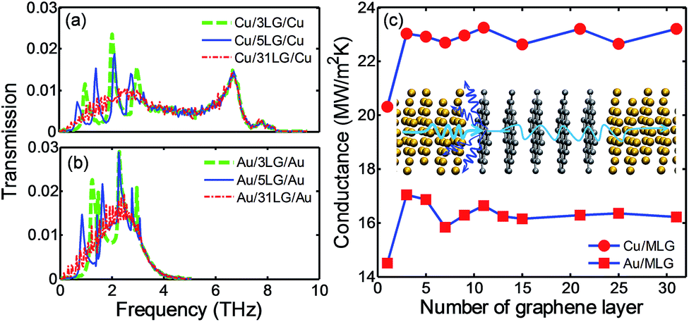 | ||
| Fig. 5 Phonon transmission as a function of frequency in (a) Cu/MLG/Cu structures and (b) Au/MLG/Au structures. (c) TBC at Cu/MLG and Au/MLG interfaces as a function of the number of graphene layers. The inset drawing in (c) shows that the dominant phonon scattering is at metal/graphene interface. | ||
Fig. 5(a) and (b) show the phonon transmission function across Cu/MLG/Cu and Au/MLG/Au interfaces for different n. The transmission function across metal/MLG are characterized with multi-peaks at frequencies below 4 THz; the number of peaks equals the number of graphene layers, e.g., 3 or 5 peaks for n = 3 or n = 5 in Fig. 5(a) and (b). As the number of graphene layers increases, the peaks diminish and become indistinguishable, e.g., transmission across 31 layers of graphene as shown in Fig. 5(a) and (b). Beyond 4 THz, the transmission curve changes are insignificant with increasing n. The transmission function from our AGF calculations is consistent with the transmission coefficients obtained from the wave-packet simulations, using MD simulations, carried out by Shen et al.19 The study in ref. 19 only considered the transmission of longitudinal acoustic (LA) phonons; fine sampling in longitudinal wave vectors and incidence angles requires a huge number of simulations as wave-packets need to be generated in each case. Our AGF calculations use plane-wave formulation with a fine sampling in a transverse Brillouin zone. Therefore, we can efficiently incorporate the transmission of all phonon modes from different incidence angles.
The peaks and valleys in transmission curves (Fig. 5) can be explained by the phonon interference effects.19 The addition of graphene layers between metal contacts increases the thickness of MLG as well as the wavelength range of the allowed phonon waves so that a new peak in transmission function is created with the addition of a new graphene layer. According to ref. 19, the oscillatory period in frequency, Δf depends on the group velocity, v of the transmitting phonons and thickness of MLG t : t = v/2Δf. The average group velocity of LA phonons in bulk graphite is around 1989 m s−1 where the group velocities at each wave vector is calculated by v(q) = dω/dq. We extract Δf from Fig. 5(a) and (b) and calculate v/2Δf. A good agreement is observed between v/2Δf and the corresponding MLG thickness t for both Cu/MLG/Cu and Au/MLG/Au structures, which indicates that the transmitting phonons may be dominated by LA phonons. This is also consistent with ref. 19 where only transmission of LA modes was calculated. Alternatively, we can interpret the peaks and valleys of transmission function in terms of phonon coupling. Increasing the number of graphene layers introduces inter-layer phonon modes in MLG and opens new channels for phonon coupling with the phonons in metal contact. The peaks in the transmission function represent good coupling between the phonons in metal contacts and the inter-layer phonon modes of MLG. The peaks of the transmission curve are below 4 THz because the phonon modes of MLG in the cross-plane direction have a spectrum below 4 THz.25,58
In comparison to the transmission function across Cu/SLG/Cu and Au/SLG/Au (Fig. 4(a)), the magnitude of the transmission function across the Cu/MLG/Cu and Au/MLG/Au interfaces does not change significantly. This indicates that the small phonon mismatch between the first layer of graphene and the following layers does not introduce a large RGG. Fig. 5(c) shows the TBC at Cu/MLG and Au/MLG interfaces as a function of n. The TBC increases by 2 to 3 MW m−2 K−1 for Cu (∼20 to 23 MW m−2 K−1) or Au contacts (∼14 to 17 MW m−2 K−1) when n increases from one to two. Increasing the graphene layers further has little effect on TBC for both Cu/MLG and Au/MLG interfaces which is also observed in MD simulations for the Cu/MLG/Cu structure in previous studies.19,31 This trend seems counterintuitive, because adding graphene layers will increase RGG and reduce the overall thermal conductance. Phonon mismatch between the first graphene layer and the following graphene layer caused by the weak physisorption interaction with Cu or Au is small, and results in small RGG. So, RMG dominates the thermal transport while RGG can be negligible for Cu/MLG or Au/MLG interfaces as illustrated in the inset of Fig. 5(c). Recent MD simulations19,31 predicted a different trend for TBC across Cu/MLG/Cu, i.e., TBC decreases significantly from Cu/SLG/Cu to Cu/MLG/Cu. It should be noted that the L-J potential is used in these studies and the corresponding IFCs are much larger than the IFCs predicted by our DFT simulations. IFCs are indications of the bonding strength between the Cu and graphene. The metal/graphene bonding strength does not only affect the phonon coupling at the metal/graphene interfaces but also the phonon coupling among the graphene layers. Its impact on phonon transmission and TBC can be different for metal/SLG/metal and metal/MLG/metal structures, which will be discussed next using the Ti/MLG/Ti structure as an example.
In comparison to Cu/MLG or Au/MLG interfaces, the Ti/MLG interface has a negligible RMG value, which is reflected in the high TBC at the Ti/SLG interface (∼1000 W m−2 K−1). As RMG is low, phonon coupling between the graphene layers with distinct phonon DOS and the associated RGG may become important for the thermal transport at the Ti/MLG interfaces. Fig. 6(a) shows the phonon transmission function across the Ti/MLG/Ti structure with n from 1 to 25. The transmission across the Ti/MLG/Ti structure with three graphene layers (n = 3) is one order of magnitude smaller than the Ti/SLG/Ti (n = 1) structure (Fig. 4(b)). As n increases beyond three, the magnitude of transmission function changes slightly. This suggests good phonon coupling among the middle graphene layers and weak phonon coupling at the interface between the first graphene layer and the following layer as expected from the significant mismatch in phonon DOS (Fig. 3(a) and (d)). Similar to the Cu/MLG/Cu and Au/MLG/Au structures, the transmission curves of Ti/MLG/Ti structures also have multiple peaks below 4 THz. But the number of peaks is less than the number of graphene layers by two, which is equal to the number of graphene layers not bonded with the Ti contacts. The peaks in the transmission curves are associated with the interference between the propagating and reflected phonons. The interference effects are only observed for the middle graphene layers in the Ti/MLG/Ti structures, which can be explained by the coupling mechanism between the phonons in metal contacts and the inter-layer phonon modes of MLG. Because of the significant mismatch in phonon DOS with the middle graphene layers, the two graphene layers bonded to Ti contacts do not contribute in the formation of the inter-layer phonon modes36,37 as in the case of Cu/MLG/Cu or Au/MLG/Au structures, and their coupling with Ti contacts is not reflected as peaks in transmission curves.
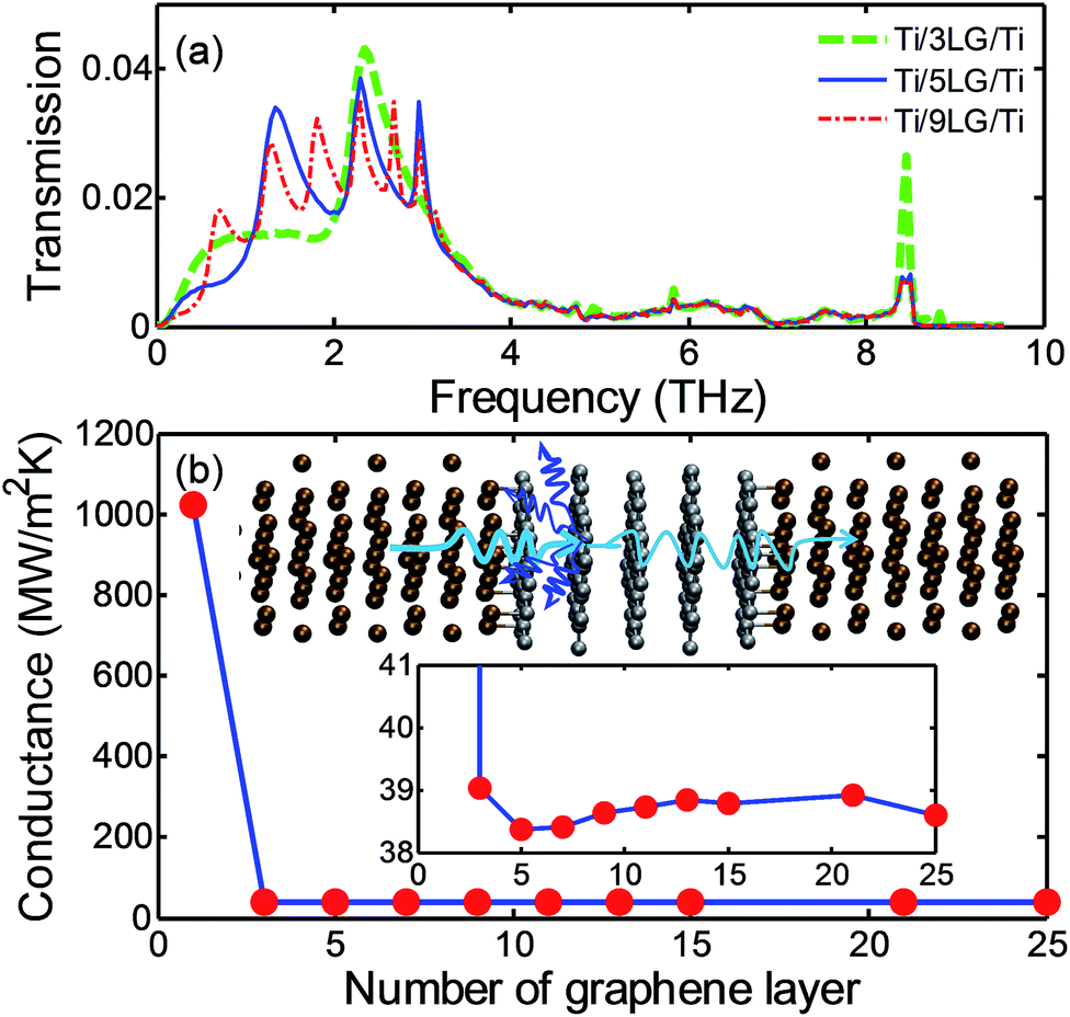 | ||
| Fig. 6 (a) Phonon transmission as a function of frequency in Ti/MLG/Ti structures. (b) TBC at Ti/MLG interfaces as a function of number of graphene layers. The upper inset in (b) shows the dominant phonon scattering is at the interface between graphene bonded to Ti and the following graphene layer. The lower inset in (b) shows TBC variations for n ≥ 3. | ||
The significant reduction in transmission function and TBC in the Ti/MLG/Ti structure by increasing n from one to three implies the importance of phonon scattering at interfaces between the graphene layers with significant phonon mismatch. Because of the harmonic assumption in AGF calculations, the phonon scattering is not realized among the non-bonded graphene layers of nearly identical phonon DOS. So, the change in TBC is very small in the Ti/MLG/Ti system as n increases beyond three. The AGF calculations predict TBC of 39 W m−2 K−1 at 300 K for smooth Ti/HOPG interfaces, which is in agreement with the experimental measurements of TBC at Ti/HOPG interfaces (∼70–100 W m−2 K−1 at around room temperature).15,16,38 Most of the experimental measurements have been performed for Ti/HOPG structures or Ti/MLG/SiO2 structures and so the dramatic decrease of TBC by increasing n from one to three has never been reported for metal/MLG/metal structures. It will be worthwhile to examine these using advanced measurement techniques such as time domain thermoreflectance. Furthermore, the Ti/graphene interfaces in the experiments may not be as smooth and clean as they are considered in the AGF calculations; the defects and roughness can change the Ti/graphene bonding strength and also number the number of bonded atoms at the interface. The decrease in Ti/graphene bonding strength will increase RMG, but the decrease of Ti/graphene bonding strength can attenuate the mismatch in phonon properties of the first and second graphene layers leading to a decrease in RGG. So, the change in TBC across Ti/MLG/Ti will depend on the interplay between RMG and RGG. To better understand this interplay, it is important to examine how the TBC will change if the bonding strength between Ti/graphene is scaled down.
Manipulating TBC across metal/MLG/metal interfaces by tuning bonding strength
We have demonstrated that the interfacial bonding strength has different effects on RMG and RGG and there is a trade-off between RMG and RGG which suggests a method that could be used to manipulate TBC across metal/MLG/metal interfaces by tuning the bonding strength. We performed a series of AGF calculations on both metal/SLG/metal and metal/MLG/metal structures by scaling the force constants (using a factor f) for SLG/metal interactions obtained from the DFT simulations. X-ray photoelectron spectroscopy of thin titanium films deposited on HOPG shows characteristics of partial carbide bonds at the Ti/HOPG interface which depends on the deposition conditions.16 Changing the deposition conditions (e.g., changing the energy of sputtering) can be analogous to changing f in the present study.Fig. 7(a) and (b) show the TBC (normalized with TBC G0 at f = 1) at 300 K as a function of the scaling factor f for Ti/SLG/Ti, Ti/3LG/Ti, Cu/SLG/Cu and Cu/3LG/Cu structures. Because the bonding strength at the chemisorption interface between Ti and graphene is inherently strong, we can scale it down in order to reduce RGG, but increase RMG. Conversely, the physisorption interaction at Cu/graphene or Au/graphene interfaces is weak, so we need to enhance the bonding strength in order to reduce RMG, but increase RGG. As shown in Fig. 7(a), the normalized TBC G/G0 across the Ti/3LG/Ti interfaces increases with decreasing f, achieves peak value at f = 0.1 and then rapidly decreases to zero. But, the G/G0 across the Ti/SLG/Ti interfaces decreases monotonically to zero with the decreasing f because RGG is absent and RMG increases with the decreasing f. At f = 0.1, the TBC across Ti/3LG/Ti at 300 K is increased by 100% and reaches 80 W m−2 K−1. Similarly to the Ti interfaces, a peak is observed in G/G0 for Cu/MLG/Cu but not for the Cu/SLG/Cu system as we increase f from 1 to 8, as shown in Fig. 7(b). Previous NEMD studies have shown the TBC across Cu/SLG/Cu can be much larger than the TBC across the Cu/MLG/Cu but the TBC for SiO2/SLG and SiO2/MLG interfaces are not very different. Our AGF calculations for the metal/MLG/metal structures with three different metals indicate that the metal/graphene bonding strength and phonon coupling among MLG are responsible for the different trends with increasing n for different substrates.
 | ||
| Fig. 7 Normalized TBC G/G0 as a function of the scaling factor f in (a) Ti/SLG/Ti and Ti/3LG/Ti structures, (b) Cu/SLG/Cu and Cu/3LG/Cu structures. G0 is the TBC in the system with f = 1. (c) G/G0 as a function of number of graphene layers n at different f for Cu/MLG/Cu structure. G0 is the TBC in the system with n = 1. | ||
Fig. 7(c) shows the variations of normalized TBC G/G0 across the Cu/MLG/Cu structure with increasing n for different scaling factors f (∼1–4). For an f equal to one, the TBC increases when n is increased from one to two, but this trend in TBC variation with n is reversed when f is increased to two. By further increasing f (to 3 or 4) this leads to an even sharper decrease in TBC when n is increased from one to two. TBC is almost constant when n > 3 for all values of f considered here. Comparison of the reduction in TBC across Cu/MLG/Cu against previous NEMD simulation results19,31 suggests that the L-J potential corresponds to these high values of f. That is why previous NEMD simulations19,31 predict a different trend of TBC for Cu/MLG/Cu structures with increasing n than our DFT and AGF calculations (f = 1). This also suggests that first principle simulations are important to accurately present the interfacial interactions.
NEMD simulations of Cu/MLG/Cu structures with different interaction strengths
The thermal resistance between non-bonded graphene layers of MLG with similar DOS is neglected in our AGF calculations because of the harmonic approximations. In order to justify the findings of AGF calculations for metal/MLG/metal interfaces, we perform NEMD simulations for Cu/SLG/Cu and Cu/3LG/Cu structures as MD simulations naturally includes all anharmonic interactions (Fig. 8(a) and (b)). The interactions between the Cu and graphene are described using a L-J potential, and the scaling factor χ is used to strengthen the interactions which are similar to scaling up f in the AGF calculations. Fig. 8(c) to (h) show the temperature profiles from the heating bath to the cooling bath under a constant heating/cooling rate of ±45 nW in Cu/SLG/Cu and Cu/3LG/Cu structures with χ = 1.0, χ = 0.2, and χ = 4.0. Table 1 summarizes the corresponding results at steady state including the equilibrium spacing between Cu and graphene dMG, the equilibrium spacing between graphene layers dGG, the temperature difference between Cu and graphene ΔTMG, the temperature difference across graphene layers ΔTMLG, and the TBC G across the interfaces. | ||
| Fig. 8 Schematic of (a) Cu/SLG/Cu and (b) Cu/3LG/Cu structures for non-equilibrium molecular dynamics simulations. Temperature profiles across Cu/SLG/Cu for (c) χ = 1.0, (e) χ = 0.2, and (g) χ = 4.0. Temperature profiles across Cu/3LG/Cu for (d) χ = 1.0, (f) χ = 0.2, and (h) χ = 4.0. χ is the scaling factor in the L-J potential model for Cu/graphene interactions. The inset in (f) shows the close up of the temperature profile in the three graphene layers. | ||
| χ = 1.0 | χ = 0.2 | χ = 4.0 | ||||
|---|---|---|---|---|---|---|
| n | 1 | 3 | 1 | 3 | 1 | 3 |
| dMG (Å) | 3 | 3.01 | 3.06 | 3.05 | 2.99 | 2.98 |
| dGG (Å) | N/A | 3.29 | N/A | 3.31 | N/A | 3.18 |
| ΔTMG (K) | 7.3 | 17.1 | 68.8 | 72.2 | 2.0 | 8.1 |
| ΔTMLG (K) | N/A | 8.1 | Neg. | Neg. | N/A | 28.8 |
| G (MW m−2 K−1) | 183.5 | 64.9 | 19.9 | 19.0 | 693.4 | 60.7 |
As shown in Table 1, the change of dMG (∼0.01 Å) is negligible as n increases from 1 to 3 when χ = 1. The same interfacial structure indicates the same interaction strength between Cu and graphene in the two structures. However, under the same heat flux, ΔTMG increases from 7.3 K to 17.1 K, and ΔTMLG is not negligible (8.1 K) in Cu/3LG/Cu. As a result, G decreases from 183.5 to 64.9 MW m−2 K−1 as shown in Table 1. The decrease (∼65%) in G with increasing n, when χ = 1, is also observed in the NEMD studies by Chang et al.31 and Shen et al.19 In this research, we clearly show, by comparing ΔTMG and ΔTMLG between Cu/SLG/Cu and Cu/3LG/Cu structures, that adding graphene layers into Cu/SLG/Cu structures leads to the increase of both RMG and RGG. As the interaction strength between Cu and graphene is same in Cu/SLG/Cu and Cu/3LG/Cu structures, we can reasonably infer that the addition of graphene/graphene interfaces reduces phonon transmission in Cu/3LG/Cu structures when χ = 1.
It is worth noting that TBC predicted by NEMD simulations with the L-J potential (χ = 1) is much larger than the TBC predicted by AGF calculations using IFCs from the DFT simulations. It implies that the interaction strength described by the L-J potential is much stronger than that predicted by DFT calculations. Because of the strong Cu/graphene interaction specified by the L-J potential in NEMD simulations, significant phonon mismatch is created between the graphene layer in contact with Cu and the middle graphene layer in the Cu/3LG/Cu structure. Based on the analysis of DOS using the AGF calculations from the previous sections, it can be inferred that the interfacial phonon coupling is weak at graphene/graphene interfaces because of the large phonon mismatch. Therefore, in the NEMD simulations, the hot phonons emitted from the heating bath will be reflected back to the left Cu contact by the graphene/graphene interfaces, which reduces the phonon transmission as well as the TBC across the Cu/3LG/Cu structure and increases both ΔTMG and ΔTMLG.
For a better comparison between the predictions of NEMD and AGF calculations, we need to use a similar interaction strength at the Cu/graphene interfaces. So we reduce χ to 0.2 in the L-J potential model, and perform the NEMD simulations under the same heat flux. As shown in Table 1, TBC predicted by NEMD simulations at χ = 0.2 is significantly reduced to 19.9 and 19.0 MW m−2 K−1 for Cu/SLG/Cu and Cu/3LG/Cu structures, respectively, which is comparable to the predictions by the AGF calculations. For Cu/3LG/Cu structure, ΔTMLG is not distinguishable whereas the temperature difference across the Cu/graphene interfaces ΔTMG is noticeable. So TBC only decreases by ∼5% as n increases from 1 to 3, which is similar to that of SiO2/MLG/SiO2 structures in the NEMD simulations by Shen et al.19 This also confirms our AGF calculations: the phonon transport is ballistic through MLG in the metal/MLG/metal structure with weak metal/graphene interaction strength.
Similarly, by scaling χ to 4 in the NEMD simulations, we can study the phonon transport across the metal/MLG/metal structures with a strong interaction strength. As shown in Fig. 8(g), the temperature variation in the Cu/SLG/Cu structure becomes non-linear near the Cu/graphene interface because the strong interfacial interaction increases phonon scattering and reduces the thermal conductivity of the near-interface region of the semi-infinite Cu contact.59 With the same interfacial interaction strength (χ = 4), the temperature variation remains linear in the Cu/3LG/Cu structure. This implies that the effects of interfacial atomic reconstruction of the metal contact are more important in the metal/SLG/metal structure with a strong interaction strength. As shown in Table 1, ΔTMLG has been larger than ΔTMG in Cu/3LG/Cu at χ = 4, which suggests that thermal resistance at the graphene/graphene interface becomes more important for the metal/MLG/metal structures with a strong interaction strength. As a result, TBC decreases by one order of magnitude as n increases from 1 to 3, which is similar to the Ti/SLG/Ti and Ti/MLG/Ti structures in the AGF calculations.
Finally, by NEMD simulations, we demonstrate the increase of ΔTGG with χ because the increasing Cu/graphene interaction strength leads to larger mismatch in the phonon DOS and the reduced phonon coupling between the first and middle graphene layer, which is consistent with results of AGF calculations. This also confirms that trends in TBC with increasing n for different metal/MLG/metal structures considered in this study will be valid even after including anharmonic interactions in the AGF calculations.
Conclusions
In conclusion, we have investigated the impact of interface bonding on the phonon transmission and TBC at metal/SLG and metal/MLG interfaces. We observed a strong electron localization at the Ti/graphene interface as a result of the chemisorption interactions; these strong interactions significantly change the phonon DOS of the graphene layer in immediate contact with metal. The physisorption interactions of graphene with Cu and Au only change the graphene DOS around the Brillouin zone center. Due to this difference in interfacial interactions, the dominant thermal resistance in Cu/MLG/Cu and Au/MLG/Au structures is at the interface of the metal and the first layer of graphene whereas the thermal resistance at the interface between the first graphene layer bonded to Ti and the middle graphene layers is more important in the Ti/MLG/Ti structures. We have shown that the TBC can be enhanced through a moderate attenuation of bonding strength at Ti/MLG interfaces which will reduce the mismatch in phonon DOS between graphene layers and effectively enhance the phonon coupling between Ti and MLG. In order to validate our AGF calculations and check the effects of anharmonic interactions, we performed NEMD simulations for Cu/SLG/Cu and Cu/MLG/Cu structures. By increasing the Cu/graphene interaction strength in the Cu/MLG/Cu structure, we show that the thermal resistance at the graphene/graphene interface becomes important and exceeds the thermal resistance at the Cu/graphene interface for high interaction strength. We expect that this study will enhance the understanding of the phonon-mediated thermal transport at metal/graphene interfaces and provide insights into tuning the TBC across MLG/metal interfaces.Acknowledgements
This work was partially supported by National Science Foundation Grant CBET-1236416.Notes and references
- A. A. Balandin, Nat. Mater., 2011, 10, 569–581 CrossRef CAS PubMed.
- C. Lee, X. D. Wei, J. W. Kysar and J. Hone, Science, 2008, 321, 385–388 CrossRef CAS PubMed.
- C. Yan, J. H. Cho and J. H. Ahn, Nanoscale, 2012, 4, 4870–4882 RSC.
- F. Bonaccorso, Z. Sun, T. Hasan and A. C. Ferrari, Nat. Photonics, 2010, 4, 611–622 CrossRef CAS.
- F. Schwierz, Nat. Nanotechnol., 2010, 5, 487–496 CrossRef CAS PubMed.
- J. X. Zheng, Y. Y. Wang, L. Wang, R. Quhe, Z. Y. Ni, W. N. Mei, Z. X. Gao, D. P. Yu, J. J. Shi and J. Lu, Sci. Rep., 2013, 3, 2081 Search PubMed.
- Y. P. Liu, W. S. Lew and L. Sun, Phys. Chem. Chem. Phys., 2011, 13, 20208–20214 RSC.
- A. Reina, X. T. Jia, J. Ho, D. Nezich, H. B. Son, V. Bulovic, M. S. Dresselhaus and J. Kong, Nano Lett., 2009, 9, 30–35 CrossRef CAS PubMed.
- J. B. Hou, Y. Y. Shao, M. W. Ellis, R. B. Moore and B. L. Yi, Phys. Chem. Chem. Phys., 2011, 13, 15384–15402 RSC.
- D. A. C. Brownson and C. E. Banks, Phys. Chem. Chem. Phys., 2012, 14, 8264–8281 RSC.
- M. Freitag, M. Steiner, Y. Martin, V. Perebeinos, Z. H. Chen, J. C. Tsang and P. Avouris, Nano Lett., 2009, 9, 1883–1888 CrossRef CAS PubMed.
- A. D. Liao, J. Z. Wu, X. R. Wang, K. Tahy, D. Jena, H. J. Dai and E. Pop, Phys. Rev. Lett., 2011, 106, 256801 CrossRef.
- P. E. Hopkins, M. Baraket, E. V. Barnat, T. E. Beechem, S. P. Kearney, J. C. Duda, J. T. Robinson and S. G. Walton, Nano Lett., 2012, 12, 590–595 CrossRef CAS PubMed.
- P. M. Norris, J. L. Smoyer, J. C. Duda and P. E. Hopkins, J. Heat Transfer, 2012, 134, 020910 CrossRef.
- A. J. Schmidt, K. C. Collins, A. J. Minnich and G. Chen, J. Appl. Phys., 2010, 107, 104907 CrossRef PubMed.
- J. J. Gengler, S. V. Shenogin, J. E. Bultman, A. K. Roy, A. A. Voevodin and C. Muratore, J. Appl. Phys., 2012, 112, 094904 CrossRef PubMed.
- L. Adamska, Y. Lin, A. J. Ross, M. Batzill and I. I. Oleynik, Phys. Rev. B: Condens. Matter Mater. Phys., 2012, 85, 195443 CrossRef.
- R. Mao, B. D. Kong, C. Gong, S. Xu, T. Jayasekera, K. Cho and K. W. Kim, Phys. Rev. B: Condens. Matter Mater. Phys., 2013, 87, 165410 CrossRef.
- M. Shen, P. K. Schelling and P. Keblinski, Phys. Rev. B: Condens. Matter Mater. Phys., 2013, 88, 045444 CrossRef.
- Y. Chalopin, N. Mingo, J. K. Diao, D. Srivastava and S. Volz, Appl. Phys. Lett., 2012, 101, 221903 CrossRef PubMed.
- L. Chen, Z. Huang and S. Kumar, Appl. Phys. Lett., 2013, 103, 123110 CrossRef PubMed.
- G. Giovannetti, P. A. Khomyakov, G. Brocks, V. M. Karpan, J. van den Brink and P. J. Kelly, Phys. Rev. Lett., 2008, 101, 026803 CrossRef CAS.
- X. J. Liu, C. Z. Wang, M. Hupalo, W. C. Lu, M. C. Tringides, Y. X. Yao and K. M. Ho, Phys. Chem. Chem. Phys., 2012, 14, 9157–9166 RSC.
- M. Harb, C. V. Schmising, H. Enquist, A. Jurgilaitis, I. Maximov, P. V. Shvets, A. N. Obraztsov, D. Khakhulin, M. Wulff and J. Larsson, Appl. Phys. Lett., 2012, 101, 233108 CrossRef PubMed.
- K. Sun, M. A. Stroscio and M. Dutta, Superlattices Microstruct., 2009, 45, 60–64 Search PubMed.
- G. Zhang and H. S. Zhang, Nanoscale, 2011, 3, 4604–4607 Search PubMed.
- A. Allard and L. Wirtz, Nano Lett., 2010, 10, 4335–4340 CrossRef CAS PubMed.
- L. Chen and S. Kumar, J. Appl. Phys., 2012, 112, 043502 CrossRef PubMed.
- J. Chen, G. Zhang and B. W. Li, Nanoscale, 2013, 5, 532–536 RSC.
- K. Chen, X. Wan, D. Q. Liu, Z. W. Kang, W. G. Xie, J. Chen, Q. Miao and J. B. Xu, Nanoscale, 2013, 5, 5784–5793 RSC.
- S. W. Chang, A. K. Nair and M. J. Buehler, J. Phys.: Condens. Matter, 2012, 24, 245301 CrossRef PubMed.
- Y. X. Ni, Y. Chalopin and S. Volz, Appl. Phys. Lett., 2013, 103, 141905 CrossRef PubMed.
- Y. X. Ni, Y. Chalopin and S. Volz, Appl. Phys. Lett., 2013, 103, 061906 CrossRef PubMed.
- M. M. Sadeghi, M. T. Pettes and L. Shi, Solid State Commun., 2012, 152, 1321–1330 CrossRef CAS PubMed.
- Z. Y. Wei, Z. H. Ni, K. D. Bi, M. H. Chen and Y. F. Chen, Phys. Lett. A, 2011, 375, 1195–1199 CrossRef CAS PubMed.
- D. Singh, J. Y. Murthy and T. S. Fisher, J. Appl. Phys., 2011, 110, 044317 CrossRef PubMed.
- L. Lindsay, D. A. Broido and N. Mingo, Phys. Rev. B: Condens. Matter Mater. Phys., 2011, 83, 235428 CrossRef.
- Y. K. Koh, M. H. Bae, D. G. Cahill and E. Pop, Nano Lett., 2010, 10, 4363–4368 CrossRef CAS PubMed.
- M. Vanin, J. J. Mortensen, A. K. Kelkkanen, J. M. Garcia-Lastra, K. S. Thygesen and K. W. Jacobsen, Phys. Rev. B: Condens. Matter Mater. Phys., 2010, 81, 081408 CrossRef.
- J. Lee, K. S. Novoselov and H. S. Shin, ACS Nano, 2011, 5, 608–612 CrossRef CAS PubMed.
- Z. Huang, T. S. Fisher and J. Y. Murthy, J. Appl. Phys., 2010, 108, 094319 CrossRef PubMed.
- W. Zhang, T. S. Fisher and N. Mingo, Numer. Heat Transfer, Part B, 2007, 51, 333–349 CrossRef CAS.
- W. Zhang, T. S. Fisher and N. Mingo, J. Heat Transfer, 2007, 129, 483–491 CrossRef CAS.
- G. Kresse and J. Furthmuller, Comput. Mater. Sci., 1996, 6, 15–50 CrossRef CAS.
- T. F. Luo and G. Chen, Phys. Chem. Chem. Phys., 2013, 15, 3389–3412 RSC.
- G. Kresse and D. Joubert, Phys. Rev. B: Condens. Matter Mater. Phys., 1999, 59, 1758–1775 CrossRef CAS.
- Z. P. Xu and M. J. Buehler, J. Phys.: Condens. Matter, 2010, 22, 485301 CrossRef PubMed.
- W. A. Saidi, M. Lee, L. Li, G. W. Zhou and A. J. H. McGaughey, Phys. Rev. B: Condens. Matter Mater. Phys., 2012, 86, 245429 CrossRef.
- H. J. Monkhorst and J. D. Pack, Phys. Rev. B: Solid State, 1976, 13, 5188–5192 Search PubMed.
- S. Plimpton, J. Comput. Phys., 1995, 117, 1–19 CrossRef CAS.
- L. Lindsay and D. A. Broido, Phys. Rev. B: Condens. Matter Mater. Phys., 2010, 81, 205441 CrossRef.
- S. M. Foiles, M. I. Baskes and M. S. Daw, Phys. Rev. B: Condens. Matter Mater. Phys., 1986, 33, 7983–7991 CrossRef CAS.
- Z. P. Xu and M. J. Buehler, ACS Nano, 2009, 3, 2767–2775 CrossRef CAS PubMed.
- Z. Y. Ong and E. Pop, Phys. Rev. B: Condens. Matter Mater. Phys., 2010, 81, 155408 Search PubMed.
- B. Silvi and A. Savin, Nature, 1994, 371, 683–686 CrossRef CAS.
- A. Savin, R. Nesper, S. Wengert and T. F. Fassler, Angew. Chem., Int. Ed., 1997, 36, 1809–1832 CrossRef PubMed.
- S. N. Steinmann, Y. R. Mo and C. Corminboeuf, Phys. Chem. Chem. Phys., 2011, 13, 20584–20592 RSC.
- R. Nicklow, H. G. Smith and N. Wakabaya, Phys. Rev. B: Solid State, 1972, 5, 4951–4962 Search PubMed.
- S. Shin, M. Kaviany, T. Desai and R. Bonner, Phys. Rev. B: Condens. Matter Mater. Phys., 2010, 82, 081302 CrossRef.
| This journal is © The Royal Society of Chemistry 2014 |