
 Open Access Article
 This Open Access Article is licensed under a Creative Commons Attribution-Non Commercial 3.0 Unported Licence
A comprehensive review of lithium-ion battery components degradation and operational considerations: a safety perspective
Idris T.
Adebanjo†
 a,
Juliana
Eko†
a,
Anita G.
Agbeyegbe
a,
Simuck F.
Yuk
bc,
Samuel V.
Cowart
*bc,
Enoch A.
Nagelli
bc,
F. John
Burpo
bc,
Jan L.
Allen
*d,
Dat T.
Tran
d,
Nishma
Bhattarai
e,
Krishna
Shah
e,
Jang-Yeon
Hwang
fg and
H. Hohyun
Sun
*a
a,
Juliana
Eko†
a,
Anita G.
Agbeyegbe
a,
Simuck F.
Yuk
bc,
Samuel V.
Cowart
*bc,
Enoch A.
Nagelli
bc,
F. John
Burpo
bc,
Jan L.
Allen
*d,
Dat T.
Tran
d,
Nishma
Bhattarai
e,
Krishna
Shah
e,
Jang-Yeon
Hwang
fg and
H. Hohyun
Sun
*a
aDepartment of Chemical and Biological Engineering, The University of Alabama, Tuscaloosa, AL 35487, USA. E-mail: hsun36@ua.edu
bDepartment of Chemistry and Life Science, United States Military Academy, West Point, NY 10996, USA. E-mail: samuel.cowart@westpoint.edu
cPhotonics Research Center, United States Military Academy, West Point, NY 10996, USA
dBattery Science Branch, U.S. Army DEVCOM Army Research Laboratory, 2800 Powder Mill Road, Adelphi, MD 20783-1138, USA. E-mail: jan.l.allen8.civ@army.mil
eDepartment of Mechanical Engineering, The University of Alabama, Tuscaloosa, AL 35487, USA
fDepartment of Energy Engineering, Hanyang University, Seoul 04763, Republic of Korea
gDepartment of Battery Engineering, Hanyang University, Seoul 04763, Republic of Korea
First published on 29th April 2025
Abstract
As the demand for sustainable energy storage solutions grows, lithium-ion batteries (LIBs) remain at the forefront of modern energy technologies, widely adopted in electric vehicles and energy storage systems. Although they offer high energy densities and reliability, their long-term usage and safety are compromised by complex structural degradation mechanisms and thermal instability, which affect their key components—cathode, anode, and electrolyte—culminating in hazardous events. To comprehensively address these challenges, this review article elaborates on the electrochemical and physicochemical properties of these key components, exploring their structural characteristics, performance in practical applications, and limitations. A thorough understanding of the degradation pathways of the key components along with various strategies to mitigate failure and enhance safety are highlighted. Finally, attention is given to the unique challenges associated with first responder applications with a specific focus on military operations in extreme environments, such as high and subzero temperatures, mechanical shocks, vibrations, and prolonged storage. This review highlights the critical need for advancements in battery design to ensure safety, durability, and long-term usability in demanding environments.
Introduction
In the pursuit of global decarbonization and electric transport, interest in advanced, zero-emission energy systems has intensified. Lithium-ion batteries (LIBs) have enjoyed much success owing to their excellent energy densities and reliability, which have been extensively field-tested. Despite the growing application cases for these batteries, their structural degradation and inherent thermal instability still pose significant safety challenges. With usage and time, the cell's internal resistance increases, and the storage capacity of their cells diminishes due to degradation mechanisms that either co-occur or trigger further mechanisms.1 Moreover, the safety hazards of LIBs are products of unwanted electrode/electrolyte side reactions that stem from structural degradations occurring in the battery during standard operations, culminating in thermal runaways.2 Thermal runaway events result from a chain of vigorous exothermic reactions that are often difficult to predict and prevent in real-time.2,3 Therefore, understanding the degradation of key components—cathode, anode, and electrolyte—is imperative because of the interplay between factors that trigger or exacerbate the degradation mechanisms of each battery component.Safety concerns surrounding LIBs have become increasingly evident, particularly in high-risk environments such as aviation, electric vehicles (EVs), and large-scale energy storage systems (ESS). Kapp et al.4 analyzed 274 thermal runaway incidents in U.S. commercial aviation from 1996 to 2019, noting a sharp rise in cases since 2015, with most incidents involving fire, smoke, or explosions. When thermal runaway occurs, it leads to the rapid release of stored energy, causing the battery to heat up dramatically, potentially leading to fire, explosion, and the release of toxic gases (Fig. 1).5 Such events are triggered by various factors, including battery cell degradation, manufacturing defects, mechanical abuse, electrical abuse, and exposure to high temperatures.6 Numerous high-profile safety incidents involving LIBs have occurred over the past decade. Notably, the Boeing 787 Dreamliner battery incidents in 2013, where two cases of battery fires led to the grounding of the entire Dreamliner fleet for several months.7 Investigations revealed that internal short-circuiting within LIB cells, due to battery design flaws and manufacturing processes, caused the fires. Similarly, in 2016, the Samsung Galaxy Note7 smartphones were recalled after battery design flaws, such as faulty separators and electrodes, led to numerous reports of the devices catching fire or exploding. This caused significant financial and reputational damage for Samsung.8 Moreso, in July 2020, in Surprise, Arizona, four firefighters were critically injured from the explosion of an LIB energy storage system (ESS).9 In 2021, the Victorian Big Battery (300 MW/400 MW h) project in Australia reported a fire outbreak in a Tesla Megapack (MP-1) caused by an internal short circuit resulting from coolant leakage in the MP-1's cooling management system.10 This leakage led to the overheating of the module's LIB cells, ultimately triggering a thermal runaway event and fire. The Surprise, Arizona, and Victorian Big Battery ESS fire incidents demonstrate the vulnerabilities of large-scale energy storage systems to thermal events and the potential for widespread damage where safety mechanisms fail.
 | ||
| Fig. 1 The stages of thermal runaway in LIBs. Reproduced with permission from ref. 11. Copyright 2018, American Association for the Advancement of Science. | ||
The aforementioned cases highlight the pressing necessity of significant research efforts and design enhancements to address the safety hazards in commercial applications. Several studies have reported the complex degradation mechanisms of LIB components to provide mitigation strategies. For instance, major cathode degradation has been identified to stem from the anisotropic volume expansion during charge/discharge cycles, particularly in Ni-rich layered cathodes when the Ni content exceeds 60%. Ryu et al.12 investigated the capacity fading mechanisms in layered Ni-rich Li[NixCoyMn1−x−y]O2 cathodes with varying Ni content (0.6 ≤ x ≤ 0.95) and found that while increasing Ni content improves discharge capacity, it also significantly reduces cycling stability, especially for compositions with x > 0.8. The degradation was primarily attributed to the anisotropic volume changes associated with the H2 → H3 phase transition, which causes significant internal stress within the cathode material owing to detrimental shrinkage in the lattice along the c-axis, leading to the formation and propagation of microcracks in the cathode particles.13–16 These microcracks create penetration pathways for the electrolyte, exacerbating degradation by allowing the electrolyte to attack the newly exposed surfaces.17
Additionally, Wu et al.18 investigated the degradation mechanisms of LIB cathode materials and observed that the performance degradation and thermal instability of Ni-rich layered LIB cathode materials occur at a surface level. They further observed that the original layered lattice structure of the material transforms into inactive and insulation NiO-like rock-salt near the surface due to the oxidation of the electrode surface contacting the electrolyte by strongly oxidizing Ni3+/4+, a phenomenon also discussed by Ryu et al.12 The degradation of cathodes is primarily linked to the instability of the crystal structure. However, the degradation mechanisms vary significantly depending on the specific cathode material, each undergoing distinct pathways that ultimately contribute to crystal structure instability. These varying mechanisms will be explored in detail in the subsequent sections.
Similarly, researchers have also investigated the degradation of anode materials. The degradation mechanisms of anodes vary by material. For instance, Li metal anodes suffer from dendrite formation and parasitic reaction of the Li with the electrolyte.19 Graphite degrades due to solvent co-intercalation, structural disordering, dissolved transition metal cation plating, and Li plating/dendritic growth.20–22 Silicon degrades because of repeated volume expansion and contraction during charge and discharge cycles, leading to mechanical stress, cracking, delamination, and pulverization of the silicon particles, resulting in loss of electrical contact, increased impedance, and rapid capacity fading.23–26
Electrolyte degradation is also a critical factor in the overall deterioration of LIBs. The mainstream electrolytes in commercial LIBs are carbonate-based, consisting of a Li salt dissolved in organic solvents.27,28 While battery electrolytes are favored for their compatibility with common anode and cathode materials and their wide electrochemical stability window, they are thermally unstable.27 Notably, LiPF6 decomposes into reactive species, such as PF5 and HF, which further react with the carbonate solvents, generating heat and gaseous byproducts.28,29 This cascade of reactions increases internal pressure within the battery, heightening the risk of thermal runaway.
To address anode and electrolyte degradation as well as thermal instability concerns, various approaches have been considered. These approaches include the use of composite anodes, solid electrolyte interphase (SEI)-forming additives, solid electrolytes, and the development of aqueous electrolytes to tackle issues like graphite exfoliation, SEI decomposition, solvent co-intercalation, dendrite formation, PF5 formation, thermal runaway, and toxic gas emissions.19,30–33
Overall, LIB component degradation is often perceived as a complex topic with multiple intertwined mechanisms occurring simultaneously. Therefore, this review aims to provide an in-depth yet comprehensive summary of the current state-of-the-art knowledge on the degradation mechanisms of key LIB components—cathode, anode, and electrolyte—and the factors that trigger or exacerbate such wear-downs. Furthermore, this safety-focused review will offer insights into recent strategies that enhance the safety and reliability of these batteries and discuss practical requirements recommended for LIB applications from the viewpoint of first responders, thus contributing uniquely to the existing literature on LIB degradation pathways and thermal instabilities.
The first section of the paper details the electrochemical and physicochemical properties of various widely used cathode, anode, and electrolyte materials. The second and third sections of this paper detail the complex and interdependent degradation mechanisms and abuse conditions of battery components that exacerbate thermal risks and trigger catastrophic cell failure. Particular attention is given to Ni-rich and Li-rich cathodes, as well as 5 V spinel cathodes, which are prone to oxygen release—a catalyst for thermal runaways. Furthermore, we discuss the unique degradation mechanisms of silicon anodes’ remarkable capacity albeit plagued by high-volume expansions and other materials such as graphite, conversion anodes, fast-charging anodes, and Li metal anodes. Given the role of electrolytes as a medium for ionic transport and their significant impact on thermal regulation, we also discuss the thermal stability and degradation of electrolytes—particularly carbonate, ether, and gel polymer electrolytes—addressing their susceptibility to decomposition and gas evolution under thermal stress, elucidating how electrolyte decomposition affects overall cell stability. The fourth section details recent strategies to enhance LIB safety using novel materials and approaches. To present a holistic and first-hand user perspective, the last sections of the review discuss application impacts and specific requirements that LIBs must meet for first responders. This includes considerations for high/fast charge–discharge rates, cycle life requirements, operating temperature ranges, system vibrations, mechanical loads in transportation (automotive, aircraft, small vehicles, drones), and specific challenges faced by first responders and military applications.
1. Electrochemical and physicochemical properties of LIB materials
a. Cathode materials
![[3 with combining macron]](https://www.rsc.org/images/entities/char_0033_0304.gif) m space group.34 These materials possess high energy density, excellent cyclability, rate capability, and versatility across various energy applications in EVs, ESS, and portable electronics. The structure of Ni-rich layered oxide cathodes is based on the α-NaFeO2 type layered structure consisting of alternating layers of Li and transition metal oxides.35 The growing demand for higher energy densities has necessitated an increase in the Ni content within these materials, as the increase in Ni content directly translates to higher energy densities.36–38 As a result, materials such as Li[Ni0.8Co0.15Al0.05]O2 cathodes, commonly used in EVs, including those manufactured by Tesla, offer a high energy density and long cycle life.
m space group.34 These materials possess high energy density, excellent cyclability, rate capability, and versatility across various energy applications in EVs, ESS, and portable electronics. The structure of Ni-rich layered oxide cathodes is based on the α-NaFeO2 type layered structure consisting of alternating layers of Li and transition metal oxides.35 The growing demand for higher energy densities has necessitated an increase in the Ni content within these materials, as the increase in Ni content directly translates to higher energy densities.36–38 As a result, materials such as Li[Ni0.8Co0.15Al0.05]O2 cathodes, commonly used in EVs, including those manufactured by Tesla, offer a high energy density and long cycle life.
With an increase in Ni content (Ni > 60%), state-of-the-art Ni-rich layered oxide materials achieve impressive energy densities of approximately 300 W h kg−1 (ref. 39) in 4680 (46 mm in diameter, 80 mm in axial length) cylindrical cells, significantly surpassing those of traditional lithium cobalt oxide (LiCoO2). One attribute of the Ni-rich layered oxides is their high voltage, which typically ranges between 3.7 and 3.9 V versus Li/Li+.39 This high voltage contributes to the battery's overall energy density, allowing for more energy storage within the same volume compared with other cathode materials. Additionally, the high Ni content contributes to an increase in the capacity because Ni provides multiple oxidation states (Ni2+/Ni3+/Ni4+)40 that facilitate electron transfer and Li+ intercalation during charge and discharge cycles. This enhanced electrochemical activity is further complemented by the stable layered structure of these oxides, which allows for a high degree of Li+ diffusion with minimal lattice distortion. Research has shown that tuning the properties of these cathode materials via lattice engineering and defect modulation using strategies such as concentration gradient and single particle engineering can significantly improve their structural stability, further minimizing lattice distortion and leading to excellent rate capability and cycling performance.41,42
The stability of Ni-rich layered oxides is bolstered by the careful balance of Ni with other elements like Co, Mn, and Al. Co plays a critical role in stabilizing the layered structure, preventing the Li+/Ni2+ mixing, and improving the thermal stability of the material. This is particularly important for maintaining the integrity of the cathode during high-temperature operations, which is a common requirement for high-performance batteries. Conversely, Mn enhances structural stability and mitigates the harmful effects of phase transitions that can occur during cycling. In the case of NCA cathodes, Al is introduced to improve the mechanical robustness and thermal stability of the material. This balance of elements not only enhances the electrochemical properties of the cathode but also ensures that the material remains relatively stable and safe under various operating conditions.43–45
Despite the high energy density and stability shown by Ni-rich layered oxides, this enhancement in energy density is accompanied by rapid structural degradation, such as microcracks and deteriorative cathode/electrolyte interfaces that can lead to thermal runaway of the cathode material. This raises significant concerns regarding the safety and practical use of these Ni-rich layered oxides. The heightened energy density, while beneficial, exacerbates the intrinsic instability of Ni-rich layered oxides, leading to accelerated deterioration of the material's structure.46
 | ||
| Fig. 2 (a) High-resolution TEM image, and (b) schematic structure of LiTMO2 and Li2MnO3 domains. Reproduced with permission from ref. 51. Copyright 2024, The Author(s). Licensed under Creative Commons CC BY(https://creativecommons.org/licenses/by/4.0/). Structures of (c) Ni-rich layered oxide, (d) and Li-rich layered oxide. Reproduced with permission from ref. 52. Copyright 2021, Elsevier B.V. | ||
Li-rich cathodes possess a layered crystal structure similar to conventional layered oxides like NCM. In these materials, Li and transition metals are arranged in alternating layers within the crystal lattice (Fig. 2c and d). The presence of excess Li in the structure beyond the stoichiometric ratio facilitates a dual redox mechanism involving both the transition metal ions and the oxygen anions. In conventional cathode materials, the capacity is primarily derived from the redox reactions of transition metals such as Ni3+/Ni4+ or Co3+/Co4+.53 However, in Li-rich materials, an additional redox activity involving oxygen anions (O2−) is activated.54 The incorporation of Li2MnO3 into the structure enables the activation of Mn ions from a tetravalent state to a trivalent state,55 which, when combined with oxygen's redox activity, significantly boosts the material's overall capacity. The activation of the oxygen redox is made possible by the excess Li in the structure, which allows oxygen to participate in the electrochemical reactions to enable much higher capacities than its other layered cousin. Li-rich layered oxides also demonstrate impressive electronic conductivity, which, although inherently lower than some other cathode materials, can be significantly improved through strategic doping and surface modifications.56
One critical attribute of Li-rich layered oxide is its outstanding thermal stability. Its decomposition temperatures are significantly higher than those of traditional cathode materials.57 This high thermal stability is attributed to the strong bonding within the layered structure and the robust lattice formed owing to the incorporation of Li2MnO3. The presence of Mn in a higher oxidation state (Mn4+) and its interaction with other transition metals contribute to this enhanced stability,58 making Li-rich layered oxide capable of withstanding higher operational temperatures than Ni-rich layered oxides.
While Li-rich layered oxide boasts of high capacity and better thermal stability than Ni-rich layered oxide materials, these materials suffer from significant capacity loss, pronounced voltage hysteresis/fade, low initial Coulombic efficiency (ICE), and poor rate performance as highlighted by Zheng et al.59 In particular, the voltage hysteresis and decay, which lead to energy insufficiency and continuous energy density loss during cycling, remain among the greatest challenges for the practical applications of Li-rich layered oxides.60,61 This instability manifests primarily through structural degradation, capacity fading, and safety concerns under elevated temperatures and prolonged cycling.
In the initial studies on the first spinel structure, LiMn2O4 in 1964 by Blasse,66 it was demonstrated that the spinel structure of LiMn2O4, with Li+ and Mn+ occupying tetrahedral and octahedral sites, respectively, delivered a theoretical specific capacity of 148.2 mA h g−1. However, its practical application was limited by the Jahn–Teller distortion of Mn3+, causing structural changes and capacity fading. Researchers addressed this by doping the spinel structure with divalent cations like Zn and Mg, which enhanced electroactivity at higher voltages. In situ XRD and XANES studies showed Mn ion oxidation during charging while Zn and Mg remained divalent. These findings linked lattice parameter shifts to electrochemical performance, laying the groundwork for high-voltage cathode materials. By partially substituting Mn with Ni, Co, or other transition metals, materials such as LiNi0.5Mn1.5O4 (LNMO) were synthesized (Fig. 3a and b). The most distinguished feature of LNMO is its remarkably high and flat voltage plateau at ∼4.7 V (vs. Li/Li+) that utilizes the entire redox capacity of Ni (Ni2+/4+). It has a remarkable energy density of ∼650 W h kg−1.67
 | ||
| Fig. 3 A side-by-side comparison between (a) a typical Ni-based NCM, and (b) the spinel 5 V cathode in terms of structural feature. Reproduced with permission from ref. 62. Copyright 2024, The Authors. Advanced Materials published by Wiley-VCH GmbH. | ||
One of the key strengths of 5 V spinel cathodes is their exceptional rate capability, primarily attributed to the spinel structure's three-dimensional Li+ diffusion channels.68,69 The diffusion of Li+ occurs through the 8a tetrahedral and 16c octahedral sites with minimal lattice distortion, which is crucial for maintaining swift ion transport. However, LNMO's practical usage is still severely limited by parasitic reactions associated with its extremely oxidative operating conditions, including the absence of a stable electrolyte at 5 V and TM dissolution, which are further exacerbated under storage or operation at elevated temperatures.
Despite their well-deserved reputation for safety, LFP cathodes are not entirely immune to thermal instability concerns. While they exhibit superior thermal stability compared to other LIB chemistries, certain factors can still trigger a potentially dangerous chain reaction within the battery, leading to thermal runaway. This phenomenon can lead to a rapid rise in temperature, potentially resulting in fire or explosion. Furthermore, the flat voltage plateau at ∼3.2 V makes it difficult for the battery management system (BMS) to detect the state of charge (SOC).
A high SOC, particularly at 100%, can lead to higher internal energy and heat transfer power, exacerbating thermal instability. External heat sources and heat conduction between cells during thermal runaway propagation can also contribute to the risk. Yang et al.79 in their comparative study on aging and thermal runaway of commercial LFP/graphite batteries undergoing slight overcharge cycling, explored how slight overcharge cycling affects the aging mechanism and thermal runaway behavior of LFP batteries. They found that overcharging accelerates capacity fading due to Li loss, with a higher risk of internal short circuits and worsened thermal stability. Zhang et al.80 using differential scanning calorimetry tests revealed that the LFP cathode exhibits high thermal stability, while the graphite anode reacts violently with the electrolyte, to produce significant heat. It was established that the key reactions include SEI decomposition, lithiated graphite reaction with electrolyte, and binder reactions at higher temperatures. Key findings indicate that onset temperatures for exothermic reactions can be as low as 70.6 °C, with significant heat and gas venting observed around 200 °C. Understanding these mechanisms is crucial for enhancing the safety of LFP batteries in applications like EVs and ESS. Song et al.81 investigated the thermal runaway propagation behavior and energy flow distribution of a 280 A h LFP battery. Their experiments revealed that thermal runaway propagation occurs primarily at 100% SOC, driven by higher internal energy and heat transfer power. Chen et al.82 conducted an experimental investigation of thermal runaway behavior and hazards of a 1440 A h LFP battery pack. They analyzed the thermal runaway propagation process, finding that heat conduction between batteries becomes the main factor as thermal runaway develops. Their findings provide insights into the implementation of firefighting and flame-retardant strategies. Qian et al.83 examined the thermal runaway vent gases from high-capacity energy storage LFPs. They focused on the composition of gases released during thermal runaway, identifying key components such as CO, H2, and CO2, which pose significant hazards.
While LFP also undergoes thermal degradation, it does so to a much lesser extent compared to Li-rich, Ni-rich, and 5 V spinel cathodes. Due to its inherently stable structure, LFP is still considered a safe and reliable material. However, given that LFP has a lower capacity than these other cathodes, this paper will not delve into further discussions on the degradation mechanisms and strategies for improving LFP. Instead, the focus will be on higher-capacity materials such as Li-rich, Ni-rich, and 5 V spinel cathodes, which present more significant opportunities and challenges for performance enhancement.
b. Anode materials
During the lithiation process though, significant structural phase transitions occur. These transitions undergo multiple crystalline phase transformations, including LiSi, Li12Si7, Li7Si3, Li13Si4, Li15Si4, and Li22Si5.85,88,89 The initial lithiation stage involves the formation of an amorphous LixSi phase, which transitions to the crystalline phases below 50 mV.85 The crystalline phases are generally more kinetically stable due to their lower formation energies but not always preferentially formed during typical electrochemical lithiation under normal operating conditions.88 The potential for these phase transitions varies, but Li+ alloying in Si anodes occurring at a low potential range of 0.01–0.5 V vs. Li/Li+ at room temperature85 plays a crucial role in the battery's performance. A low lithiation potential enables efficient alloying, significantly contributing to the high energy density of the battery. However, while the low lithiation potential is advantageous for maximizing energy density, it can increase the risk of Li plating, as the low discharge potential of Si, below 0.4 V vs. Li/Li+, is lower than that of other alloy-type, carbonaceous, or metal oxide anodes.84,86,89 Conversely, the low discharge potential allows for a higher overall cell voltage when paired with high-voltage cathodes during LIB operation, maximizing the energy density of the battery. Moreover, lithiated Si is reported to be considerably less reactive than graphite, offering better chemical stability across a wider range of electrolytes.
Currently, the practical application of pure Si or high Si-anodes is hindered by significant volume expansions during lithiation/delithiation, leading to material fracturing, pulverization, and delamination from current collectors. This results in poor cycling performance and low electronic conductivity. To mitigate these issues, research has increasingly focused on Si-containing composites, such as silicon-graphite/carbon blends, and Si-based derivatives like silicon oxide (SiOx). These composites offer a more balanced performance by reducing volume change, improving mechanical stability, and enhancing cycle life, making the use of Si as an anode material more suitable for practical high-energy batteries.90 Owing to these, recent studies,91 have demonstrated that Si-based composites, especially those integrated with carbonaceous materials like artificial graphite, significantly enhance the electrochemical performance of Si anodes. This composite offers better cycling stability and rate capability, delivering a specific capacity of 445 mA h g−1 and 94% retention over 200 cycles. Pan et al.92 demonstrated the advantage of SiO, another class of Si-derived anodes. Their study highlighted that SiO anodes offer significantly lower volume expansion (∼118%) compared to pure Si (∼280%), leading to improved mechanical stability and durability during cycling. SiO also demonstrates superior rate capabilities, excelling in both fast-charging and fast-discharging due to enhanced Li+ diffusion facilitated by the Li4SiO4 matrix. Future innovations in Si-anode technology will be pivotal in unlocking its full potential in LIB applications. In subsequent sections, novel strategies aimed at improving the performance of this promising anode material will be discussed extensively.
Conversion anode materials consist of transition metal oxides, sulfides, selenides, fluorides, nitrides, and phosphides that store Li+ through reversible conversion redox reactions between the Li+ and TM cations,25 resulting in the formation and decomposition of metal nanoparticles embedded in a Li compound matrix (ex: Li2O in the case of TM oxides).93 This reaction mechanism offers several advantages over traditional intercalation-based anodes by enabling the storage of more Li+, achieving higher specific capacities of 500–1500 mA h g−1. Poizot et al.93 reported in 2000 that Li+ can be reversibly stored by conversion anodes and demonstrated that these materials could deliver exceptionally high capacities. For example, CoO was shown to exhibit capacities of around 700 mA h g−1, which is approximately twice that of graphite anodes. This is because the conversion reaction involves multiple electrons per formula unit, unlike intercalation materials that typically involve only one or two electrons.94 Additionally, conversion anodes can maintain a significant portion of their capacity after cycling, albeit with nano structuring and material engineering. For instance, nano-sized CoO showed excellent capacity retention even after 100 cycles, retaining 85% of its capacity even at 2C.93 Furthermore, the higher operating voltage range of 0.5 to 1.0 V vs. Li/Li+ reduces the risk of Li plating and dendrite formation, translating to enhanced safety and stability.95
The chemistry of conversion-type anodes also allows for the tuning of their electrochemical potential because the cell potential is directly linked to the strength of the ionic bond between the TM cation and anionic species.94 These materials can also be engineered into nanostructures, such as nanoparticles, nanowires, and nanosheets, to enhance their electrochemical activity.25 Nanosizing reduces the diffusion distances for Li+ and electrons, thereby improving the kinetics of the conversion reactions. Nanostructuring reduces the volume changes associated with conversion reactions. By designing hierarchical or hollow nanostructures, it is possible to accommodate the strain induced by these volume changes, thereby enhancing the cyclability of the conversion anode materials. The Li storage performance of some nano-structured and hollow conversion anode is given in Table 1.
| Classification | Typical example | Voltage plateau (V versus Li/Li+) | Capacity (mA h g−1) | Current density (mA g−1) |
|---|---|---|---|---|
| 0D to 3D nanostructures | CuP2 nanowires96 | 0.6 | 945 after 100 cycles | 100 |
| Co3O4 nanosheets97 | 1.0 | 1291 after 25 cycles | 445 | |
| Hierarchical configurations | MoS2 nanospheres98 | 0.6 | 1096 after 110 cycles | 100 |
| MnCo2O4 nanosheet array99 | 0.8 | 460 after 30 cycles | 800 | |
| Hollow structures | Fe3O4 hollow spheres100 | 0.7 | 1046 after 100 cycles | 500 |
| MoS2 nanotube101 | 0.6 | 839 after 50 cycles | 100 |
In terms of contribution to final energy density on a full-cell level, graphite is superior to common anodes because of its low average de-/lithiation potential of 0.2 V vs. Li/Li+,103 which is only surpassed by metallic Li. The Coulombic efficiency of graphite, which is associated with voltage hysteresis—the discrepancy between the discharge and charge potentials—is another important factor contributing to its commercial dominance.103 Although there has been some progress in lowering voltage hysteresis for materials of the conversion and alloying types, particularly with pre-lithiation and restricting delithiation to small potential ranges, graphite continues to provide a better balance of energy density and efficiency.
Graphite's slow kinetics under high charge/discharge rates, however, limit its fast-charge applications. Improving its structure and morphology can extend its use in fast-charging applications. Methods such as increasing the interlayer spacing of graphite, creating porous structures to shorten Li+ diffusion paths, and making interfacial modifications to enhance Li+ diffusion within the material have been effective.104
From a physicochemical perspective, Li metal stands out due to its exceptionally low density of 0.534 g cm−3 among all metals.107 This property significantly enhances its specific energy, making Li metal batteries highly appealing for weight-sensitive applications. Its body-centered cubic (bcc) crystal structure also facilitates relatively easy ion diffusion, supporting efficient charge–discharge cycles.108 Additionally, Li's low density contributes to its mechanical softness and flexibility, allowing it to be easily shaped into thin electrodes or novel cell designs for commercial production. Li metal's low density also imparts mechanical softness and flexibility, allowing Li metal to be easily formed into thin electrodes or novel cell architectures for commercial use.
However, the practical application of Li metal anodes is historically limited by issues such as dendrite formation and SEI instability. During cycling, the formation and dissolution of Li deposits occur on the anode surface due to uneven or localized Li deposition, potentially leading to the formation of dendritic(needle-like) structures. These dendrites pose the risk of penetrating the separator, potentially causing internal short circuits and presenting significant safety hazards.109,110 To address these issues, recent research has focused on developing advanced electrolytes, protective coatings, and novel architectures to stabilize the Li metal surface and improve its electrochemical performance. These strategies will be discussed in-depth in Section 4.
The spinel Li4Ti5O12 (LTO) offers fast-charging capability with high Li kinetics due to its higher intercalation potential of approximately 1.5 V versus Li+/Li, which prevents the formation of a SEI layer and mitigates Li metal plating.113,114 LTO anodes are characterized by a zero-strain insertion process and undergo minimal volumetric change, making them highly durable and resistant to mechanical degradation.115 However, LTO is limited by a low Li intercalation capacity of ∼160 mA h g−1.116,117 To address this limitation, Nb-based Wadsley–Roth structure-based anodes, which feature ReO3-like blocks connected in various configurations to enhance capacity and performance, were developed (Fig. 4).
 | ||
| Fig. 4 (a) Crystal structure of NaNb13O33 viewed down the b-axis. Green octahedra represent Nb-centered NbO6. Na atoms are in blue, O atoms in orange. (b) Delithiation capacity as a function of the rate of NaNb13O33 with high-rate capability up to 20C in a Li metal half-cell at the indicated charge–discharge rates. Reproduced under the terms of the Creative Commons CC BY license.118 Copyright 2023, The Authors. ChemElectroChem published by Wiley-VCH GmbH. | ||
Wadsley–Roth structures are mixed-valence metal oxides with flexible, non-stoichiometric frameworks derived from the ReO3 structure. These materials feature oxygen vacancies and ion-conducting pathways, allowing for rapid ion migration. Their structural adaptability and ability to support multiple redox states make them ideal for fast-charging battery anodes, enabling efficient ion insertion and extraction while maintaining cycling stability.119–121
Han et al.114 introduced a new Li-insertion anode material, TiNb2O7 (TNO), which operates within a voltage range of 1.3–1.6 V versus Li+/Li. The Wadsley–Roth shear structure provides significant advantages for fast charging by preventing the formation of an SEI layer. With a theoretical capacity of 387.6 mA h g−1 that is enabled by overlapping redox couples, the material's performance is further improved by substituting Nb for Ti and applying a carbon coating. Allen et al.118 investigated the potential of NaNb13O33 as an anode material for fast-charging batteries and reported a capacity of 233 mA h g−1 when cycling between 3.0 V and 1.0 V, along with high Li+ conductivity and superior rate capability. The structure of NaNb13O33, consisting of NbO6 octahedra arranged in a Wadsley–Roth framework, allows for efficient Li+ transport due to large open channels. Electrochemical measurements using PITT and EIS confirmed the superior diffusion rates of Li within NaNb13O33. Preefer et al.122 investigated the electrochemical behavior of PNb9O25 (PNO) and demonstrated that the material can support high-rate charging by undergoing an insulator-to-metal transition upon Li insertion, contributing to its notable performance. The study indicates that PNO can attain 85% of its theoretical capacity within 30 minutes, resulting in an efficient charge–discharge cycle with excellent capacity retention. Although Wadsley–Roth structured anodes show promise for fast-charging applications, they often experience capacity fading over extended cycles, highlighting the need for improvements in cycle life before they can be viable for practical use. Many of these anode materials are still in the experimental phase and require further development and optimization. Additionally, they heavily rely on high-cost transition metals.
c. Electrolytes
| Solvent | Flash point (°C) | Boiling point (°C) | Melting point (°C) | Density@25 °C (g cm−3) | Viscosity@25 °C (cP) | Dielectric constant (ε) |
|---|---|---|---|---|---|---|
| Ethylene carbonate (EC) | 160 | 238 | 36.4 | 1.32 | 1.90 (40 °C) | 89.8 |
| Propylene carbonate (PC) | 132 | 242 | −48.8 | 1.20 | 2.53 | 66.1 |
| Fluoroethylene carbonate (FEC) | 120 | 249 | 18 | 1.48 | 4.1 | 79.7 |
| Vinylene carbonate (VC) | 130 | 162 | 22 | 1.35 | 1.54 | 126 |
| Dimethyl carbonate (DMC) | 17 | 90 | 4.6 | 1.06 | 0.59 (20 °C) | 3.1 |
| Diethyl carbonate (DEC) | 25 | 127 | −74.3 | 0.97 | 0.75 | 2.8 |
| Ethyl methyl carbonate (EMC) | 27 | 108 | −53 | 1.01 | 0.65 | 2.4 |
As the table shows, cyclic and linear carbonates differ significantly in their physicochemical properties. Cyclic carbonates, such as EC, PC, and FEC, are characterized by high dielectric constants, which are crucial for dissolving Li salts effectively and ensuring a stable SEI on the anode surface. The high flash points, low volatility, and boiling points also contribute to their thermal stability. EC has an extremely high dielectric constant (89.8) and is essential in forming a robust SEI on graphite anodes when it decomposes at 0.8 V vs. Li/Li+.125
This makes it a crucial cyclic carbonate in LIB applications.125 However, with a melting point of ∼37 °C, EC is a solid at room temperature and easily solidifies when used as a solvent in low-temperature electrolyte formulations,126 severely impacting its ionic conductivity.
To overcome this limitation, linear carbonates are used as co-solvents to improve the performance of electrolyte mixtures, allowing a more balanced electrolyte formulation. It is also noteworthy that although PC and EC have comparable physicochemical properties and molecular structures, PC is known to co-intercalate into graphite layers more readily than other carbonate solvents, leading to the mechanical instability of PC-based SEIs.126 Due to the importance of SEI and anode stability in Li+ chemistry, this limits the application of PC in commercial electrolyte formulations. Among the cyclic carbonates, FEC is widely recognized for its ability to decompose and form SEI layers with the desirable LiF which has an ionic conductivity of 10−7 to 10−13 S cm−1.127 Furthermore, VC is often used as an additive in carbonate electrolyte formulations because of its lower reduction activation energy compared to EC. This property allows the early formation of a stable SEI before the onset of Li+ intercalation.128
Linear carbonates, such as DMC, DEC, and EMC, have lower viscosities, dielectric constants, flashpoints, and melting points129 but are essential in improving the wettability, viscosity, and ionic conductivity of the electrolyte. Using low-viscosity solvents alone, however, leads to issues with Li salt solubility, SEI stability, and most importantly flammability. Thus, a balanced mixture of cyclic and linear carbonates is often employed. By mixing these solvents, the merits of individual solvents are imparted on the resultant electrolyte mixture. For instance, a mixture of EC and DMC benefits from the low viscosity of DMC, which enhances ionic conductivity, and the high dielectric constant of EC, which facilitates the dissolution of Li salts and the formation of stable SEIs.123 From an electrochemical perspective, carbonate electrolytes offer a wide electrochemical stability window, typically between ∼1.5–4.5 V vs. Li/Li+ and high ambient-temperature ionic conductivity of ∼10−2 S cm−1,130 making them compatible with both high-voltage cathodes and low-potential anodes like graphite.
The choice of Li salt in carbonate electrolytes also plays a significant role in the overall electrolyte performance, making the properties of Li salts crucial. LiPF6 is favored in commercial carbonate electrolytes due to its high ionic conductivity. For instance, LiPF6 in EC/DEC or EC/DMC electrolyte formulations yield ionic conductivities up to 10−2 S cm−1 with oxidation potential >4.5 V vs. Li/Li+.128 However, the thermal property is a challenge for carbonate electrolytes, prompting increased interest in alternative salts, such as lithium bis(trifluoromethansulfonyl)imide (LiTFSI) and lithium bis(fluoromethansulfonyl)imide (LiFSI). These salts offer excellent thermal stability, lower toxicity, and decent electrochemical properties, along with providing a more inorganic-rich SEI layer.128 However, the application of LiTFSI is hindered by its corrosive reaction with Al foil, which is typically used as a current collector in LIBs.128 Therefore, the tradeoffs in the cost and electrolyte properties must be carefully considered when switching from LiPF6 to LiTFSI/LiFSI or other Li salts.
| Solvent | Flash point (°C) | Boiling point (°C) | Melting point (°C) | Density@25 °C (g cm−3) | Viscosity@25 °C (cP) | Dielectric constant (ε) |
|---|---|---|---|---|---|---|
| Dimethoxyethane (DME) | 0 | 83 | −58 | 0.86 | 0.46 | 7.2 |
| Dioxolane (DOL) | 1 | 74 | −97.2 | 1.06 | 0.6 | 7.1 |
| Tetrahydrofuran (THF) | −14 | 66 | −109 | 0.88 | 0.46 | 7.4 |
| Tetraethylene glycol dimethyl ether (TEGDME) | 106 | 216 | −45 | 0.99 | 2.73 | 7.9 |
The compatibility of these solvents with LMAs is primarily attributed to their high donor numbers and effective Li+ solvation ability. Barchasz et al.133 highlighted the critical role of this Li+ solvation ability and the high donor number (DN) of ether-based electrolytes. Ether solvents like TEGDME with relatively high donor numbers (DN = 18.6) were shown to solvate Li+ better, creating a solvation environment that not only enhances ionic conductivity but also accelerates the passivation of the anode surface, thereby extending battery life.
The low viscosities and stability of ether solvents play a crucial role in minimizing electrolyte decomposition and suppressing dendrite formation, resulting in improved Coulombic efficiency (CE) and cycling stability when paired with LMAs.134,135 Park et al.135 conducted ab initio and statistical simulations to investigate why ether solvents are particularly compatible with LMAs. They found that the low reduction potentials of these solvents (ex: DME = −1.68 V vs. Li/Li+) are crucial to their stability, which reduces the likelihood of electrolyte decomposition with highly reactive Li metal. This stability is essential for maintaining a stable SEI and preventing dendrite formation. The study also emphasized the significant impact of low viscosity and salt anion size on dendrite suppression. This was demonstrated by the extended short-circuiting time of Li symmetric cells cycled in 1 M LiTFSI in DME, a low-viscosity solvent (Table 3). It was observed that the larger TFSI− anion (radius = 0.326 nm) contributes to higher Li+ transference numbers, which promotes uniform Li deposition and further reduces the formation of dendrites.
The polymer matrix plays a crucial role in defining the mechanical strength profile of GPEs, offering superior mechanical properties, such as tensile strengths exceeding 10 MPa in some GPEs144 to tolerate the volume changes of electrodes. The flexible nature of the polymer matrix in GPEs enables them to accommodate the formation and growth of Li dendrites. Additionally, GPEs can function as both an electrolyte and a separator,145 further enhancing their utility by providing a dual-function component that prevents short circuits and ensures reliable operation.
Compared to conventional solid polymer electrolytes (SPEs), the improved ionic conductivity of GPEs at room temperature is largely attributed to the incorporation of a liquid electrolyte (plasticizer) within the polymer matrix that plays a significant role in determining ionic conductivity and thermal stability. For instance, GPEs with PVDF-HFP as the matrix have demonstrated high ionic conductivity, typically in the range of 10−3 S cm−1,144,146 which is comparable to conventional liquid electrolytes. GPEs also offer a wide electrochemical stability window, often up to 4.3 V versus Li+/Li.144
Properties such as a low glass transition temperature (Tg), high decomposition temperature, and high melting temperature of the polymer matrix are also important properties for selecting a polymeric host for GPE application in LIBs, as these properties significantly affect the thermal behavior of GPEs.142 The chemical structure of the polymeric host also affects the behavior of GPEs, especially their thermal behavior. As such, the unique combination of high ionic conductivity, mechanical stability, enhanced safety, and the ability to function as both an electrolyte and separator provided by GPEs makes them ideal candidates for the next generation of LIBs. Their ability to maintain performance under varying conditions while offering a safer alternative to liquid electrolytes positions them as a key material in the advancement of LIB technology.
2. Degradation pathways pushing cells to catastrophic failure
a. Cathode materials
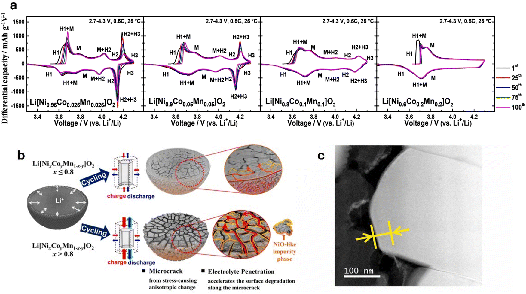 | ||
| Fig. 5 (a) dQ dV−1 profiles of Li[NixCoyMn1–x–y]O2 (x = 0.95, 0.9, 0.8, and 0.6) illustrating the H2 → H3 phase transition of varying Ni content cathode materials. Reproduced with permission from ref. 151. Copyright 2018, American Chemical Society. (b) Schematic representation of the degradation mechanisms in Ni-rich cathodes. Cathodes with less than 80% Ni primarily degrade due to surface deterioration, whereas those with Ni content exceeding 80% experience degradation through microcrack formation along grain boundaries. These cracks facilitate electrolyte infiltration, leading to the formation of a NiO-like rock salt phase. Reproduced under the terms of the Creative Commons CC-BY-NC-ND License.152 Copyright 2020, American Chemical Society. (c) STEM–EELS image of phase-transition layer. Reproduced with permission from ref. 153. Copyright 2021, Journal of Power Sources published by Elsevier B.V. | ||
Trevisanello et al.154 highlighted this by reporting that the specific surface area of pristine LiNi0.8Co0.1Mn0.1O2 cathode increased to ∼1.4 m2 g−1 from 0.2 m2 g−1 when charged to 4.2 V (vs. Li/Li+), owing to microcrack formation. Kang et al.153 reported the capacity retention of a Ni0.85Co0.10Mn0.05O2 dropping to 45.1% at 4.4 V after 300 cycles. The degradation is linked to the growth of a phase-transition layer from 10 nm to 25 nm (Fig. 5c), increasing resistance and hindering Li+ diffusion. Surface cracks from volume changes and oxygen evolution at high voltages further accelerate performance loss. Noh et al.155 indicated that NCM cathodes with Ni ≥ 60% react with air to form Li2CO3 and LiOH on the cathode surface. LiOH then reacts with the electrolyte to produce HF acid, leading to electrolyte decomposition and corrosion of electrode materials. Li2CO3 leads to gas evolution which causes significant swelling of the cathode/battery cell, particularly during high-temperature storage and in the charged state. Furthermore, residual Li compounds increase the cathode surface's alkalinity, degrading the PVDF binder. This degradation forms a gel-like network that obstructs electrode–electrolyte contact, impairing ionic conductivity and electron transfer, which reduces cycling capacity, increases internal resistance, elevates charge/discharge rates, and causes overall battery degradation.
Additionally, the similarity in ionic radii between Li+ and Ni2+ facilitates Li+/Ni2+ exchange due to the low potential barrier for Ni2+ migration to the Li+ 3b site. During charging, Li+ vacancies in the positive electrode are occupied by migrating Ni2+, which hinder the return of Li+ during discharge. In a highly delithiated state, Ni2+ continues to migrate to Li+ vacancies (octahedral 3b sites), leading to inevitable cation mixing and the release of lattice oxygen due to structural instability, disrupting the local structure and weakening the overall stability of the cathode, thus impacting its performance and lifespan.156,157 These degradation mechanisms lead to capacity fading, increased impedance, and a reduced cycle life.
 | ||
| Fig. 6 (a) Voltage curve in the 1st cycle. Reproduced with permission from ref. 52. Copyright 2021, Chinese Society of Particuology and Institute of Process Engineering, (b) atomic-scale changes to ordering within the TM layer. BOP means the beginning of plateau, FC means full charge, FD means full discharge, and (c) macroscale changes to the cathode particles. Reproduced with permission from ref. 163. Copyright 2020, The Authors. (d) Cycling performances. Reproduced with permission from ref. 52. Copyright 2021, Chinese Society of Particuology and Institute of Process Engineering. | ||
Li et al.164 reported that TM migration and dissolution caused by oxygen release is the primary cause of degradation with Li1.2Mn0.6Ni0.2O2 releasing 0.31 μmol mg−1 of oxygen and experiencing a voltage decay of 2.4 mV per cycle. Tao et al.165 using in situ and ex situ X-ray absorption spectroscopy combined with first-principles calculations, revealed that the formation of 27% oxygen vacancies led to a decrease in charge capacity from 393 mA h g−1 and discharge capacity from 294 mA h g−1 at 0.1C, to 194 mA h g−1 after 100 cycles. The release of lattice oxygen induces structural changes,166 raises internal cell pressure, and catalyzes the oxidative decomposition of the electrolyte. This process forms a thick, resistive cathode–electrolyte interphase (CEI), hindering Li+ transport and contributing to the low initial Coulombic efficiency in Li-rich layered oxides. Hence, the growth of the spinel phase and surface defect spinel layer are deemed as the primary factors contributing to poor electrochemical performance. These degradations result in voltage fading in Li-rich cathode materials (Fig. 6d), typically when the integrity and order of the layered structure cannot be fully maintained during cycling at high cutoff voltages.
The key degradation mechanism discussed for Ni-rich layered oxides, Li-rich layered materials, and 5 V spinel cathodes are summarized in Table 4 to highlight their distinct failure modes.
| Cathode material | Composition | Capacity fade rate | Key degradation mechanisms | Ref. |
|---|---|---|---|---|
| Ni-rich layered oxide | LiNi0.6Co0.2Mn0.2O2 | 0.035%/cycle (100 cycle, 0.5C, 4.3 V, 30 °C) | Minor microcracks; limited surface degradation (∼5 nm); no significant H2 → H3 transition; stable cycling; damage mostly reversible. | 169 |
| LiNi0.8Co0.1Mn0.1O2 | 0.050%/cycle (100 cycles, 0.5C, 4.3 V, 30 °C) | Emerging H2 → H3 transition, some microcracks, modest rock-salt surface (∼7–8 nm). | ||
| LiNi0.90Co0.05Mn0.05O2 | 0.150%/cycle (100 cycles, 0.5C, 4.3 V, 30 °C) | Strong H2 → H3, Δc ∼ −5.5%, microcracks propagate to surface, electrolyte ingress, interior degradation. | ||
| LiNi0.95Co0.025Mn0.025O2 | 0.170%/cycle (100 cycles, 0.5C, 4.3 V, 30 °C) | Severe H2 → H3, Δc ∼ −6.9%, deep cracks, thick rock-salt layer (up to 20 nm), interior failure. | ||
| LiNi0.90Co0.05Mn0.05O2 | 0.150%/cycle (100 cycles, 0.5C, 4.3 V, 30 °C) | Severe microcracking enables electrolyte infiltration, leading to thick rock-salt layers, reduced Li+ diffusion, increased interfacial resistance, and electrochemical insulation. | 16 | |
| Li1.03Ni0.85Co0.10Mn0.05O2 | 0.183%/cycle (300 cycles, 0.2C, 4.4 V, 25 °C) | Surface phase transition layer thickening (10–25 nm); continuous cation mixing; crack formation; Li diffusion resistance rise; spontaneous oxygen release at high voltage | 153 | |
| Li-rich layered oxide | Li1.2Mn0.6Ni0.2O2 | 0.185%/cycle (100 cycles, 4.8 V, 0.2C) | Transition metal migration, oxygen release, layered-to-spinel/rock-salt phase transitions, and structural collapse during cycling due to oxygen vacancy. | 170 |
| 0.5Li2MnO3·0.5LiNi1/3Co1/3Mn1/3O2 | 0.330%/cycle (100 cycles, 0.1C, 4.5 V 25 °C) | Irreversible oxygen loss (∼27% vacancies), MnO6 distortion, phase transformation to MnO2, structural disorder, and TMO6 contraction | 165 | |
| Li1.2Ni0.2Mn0.6O2/Li1.2Ni0.1Mn0.525Co0.175O2 | 0.172%/cycle (100 cycles, 0.33C, 4.6 V, 30 °C) | Oxygen loss; TM migration into Li layer; layered-to-spinel transformation; amorphization; strain; crack and pore formation; mosaic spinel domains | 166 | |
| 5 V spinel | LiNi0.5Mn1.5O4 | 0.50%/cycle (100 cycles, 30C, 4.8 V, 0.1C) | Active Li+ loss; Mn dissolution; SEI formation on graphite; electrolyte oxidation at high voltage; Li+ trapping | 168 |
b. Anode materials
 | ||
| Fig. 7 (a) The main degradation mechanisms of Si anode. Reproduced from ref. 174. Copyright 2016, Macmillan Publishers Limited. (b) Photoacoustic infrared spectroscopy of the interfacial layer formed on Si-anode surface from unwanted reaction with LiPF6-based carbonate electrolyte. Reproduced with permission from ref. 173. Copyright 2014, The Royal Society of Chemistry. | ||
Furthermore, during dealloying, Si undergoes considerable volume shrinkage, causing regions of the Si that became amorphous during lithiation (due to the structural disruption from Li insertion) to recrystallize into small crystalline grains called nanograins. These nanograins introduce grain boundaries that are prone to mechanical failure.26 In a LiPF6 electrolyte, the amorphous silicon surface also rapidly reacts with the electrolyte to form a 35 Å interface layer173 that consumes electrochemically active Si. Veith et al.173 estimated that this 35 Å interface formation leads to a 17% consumption of electrochemically active Si, effectively lowering the capacity of the Si anode.
Recent studies have highlighted the critical role of chemical degradation as well. For instance, Kim et al.26 highlighted that even before cycling, reactions between Si and the electrolyte result in the corrosion of Si anodes, causing dissolution of Si ions. These dissolved Si ions, along with pulverized Si fragments, block the pores of the separator to impede Li+ diffusion and charge transfer. Furthermore, in LiPF6-based carbonate electrolytes, non-electrochemically driven Si–O and Si–F bonds form on the surface of the Si anodes (Fig. 7b), consuming active Si.26 The Si–O groups react with HF generated during the decomposition of LiPF6 causing further dissolution of Si and the formation of water molecules that trigger further HF generation and continuous Si corrosion.26,173 The generation of HF coupled with rising cell temperature resulting from increasing cell impedance, creates conducive environments capable of triggering and sustaining thermal runaway events.
Over-lithiation, which can occur during battery operations through overcharging, introduces additional complications. Wang et al.175 demonstrated that over-lithiation promotes Li plating on Si surfaces, to compete with the alloying process. The resulting localized Li plating forms dendrites that puncture the separator and cause internal short circuits. Additionally, over-lithiation accelerates the formation of crystalline Li15Si4, which exacerbates voltage hysteresis.
During cycling, these anode materials also undergo significant structural reorganization, resulting in substantial expansions and contractions. The large volume changes create mechanical stress, leading to fracturing, cracking, and eventual electronic isolation of active material particles.130 As with other types of anode materials, the mechanical cracks from the repeated structural reorganization expose fresh surfaces, driving excessive SEI growth. For instance, metal fluoride (MF) particles in liquid electrolyte become coated with up to 20 nm thick SEI layer from metal (M) catalysis.177 However, due to morphological changes and separation of LiF and M clusters, this formed SEI becomes too brittle to accommodate the volume change in the active material,177 causing exposure of fresh surfaces to the electrolyte, followed by the irreversible loss of Li and the leaching of M1+/2+/3+ cations and F− anions.177 At elevated temperatures, the degradation phenomenon intensifies.
The conversion reaction mechanism transforms the active material into metallic nanoparticles dispersed in a Li compound matrix. The key to stable cycling of conversion anodes relies significantly on the formation of metallic nanoparticles with high interfacial surface area and high activity towards decomposition upon lithiation.130 Typically, nanostructured active materials offer benefits, such as a larger electrode–electrolyte contact area, shorter Li+ diffusion paths, and improved reactivity. However, nanoparticles are susceptible to agglomeration, which lead to a loss of the initial nanostructure and reduction in the reversible conversion reaction efficiency. The uneven stress distribution that could result from the agglomerated nanometallic particles leads to mechanical fractures that further contribute to the disconnection of the active materials from the current collector. This issue is particularly pronounced when the size of the nanoparticles is ∼10 nm, reducing the likelihood of re-engaging in the conversion process during subsequent cycles.176
The kinetics of the conversion reaction also contribute to degradation. Conversion reactions are typically slower than intercalation processes, owing to the multi-electron transfer mechanism involved in the reduction and oxidation of the metal compounds. The kinetics of conversion reactions are also influenced by a host of other factors, including diffusion coefficients of cations and anions, electronic and ionic conductivity of the newly formed phases, interfacial energetics,178 the crystal structure of the host lattice, and the diffusion length of metals during cation exchange.179 McDowell et al.179 demonstrated this using different metal sulfides. They noted that copper atoms in Cu2S for instance move more freely because they have longer diffusion lengths, leading to a faster conversion reaction. However, in FeS2, iron atoms cannot move as easily because their diffusion lengths are much shorter, especially at room temperature. This makes it harder for the conversion reaction to proceed easily in FeS2. This sluggish kinetics leads to poor rate performance, particularly under fast charging and discharging conditions. The dissolution of transition metals in liquid electrolytes, polysulfide dissolution, and incomplete reconversion reactions also contribute to the degradation of conversion-type anodes.180–182
 | ||
| Fig. 8 (a) Crack formation of graphite particles induced by cycling, (b) volume change of a graphite electrode as a function of Li content during lithiation and SEM image of cracks, (c) TM content obtained in a graphite anode after 120 cycles, (d) TOF-SIMS depth profiles of graphite anode after 3000 cycles, and (e) schematic representation of the SEI film evolution at a graphite electrode during cycling under the influence of chemical crossover from the cathode. Reproduced with permission from ref. 15. Copyright 2021, The Authors. Advanced Energy Materials published by Wiley-VCH GmbH. | ||
A more serious degradation of graphite results from the precipitation of dissolved transition metal cations (Ni2+, Mn2+, and Co2+) from the cathode onto the graphite surface. The deposited transition metal components cover significant portions of graphite, impeding Li+ intercalation and increasing local current density, which accelerates Li deposition.20
These cations catalyze parasitic reactions within the SEI, promoting further thickening, structural instability, and the formation of non-uniform SEI layers.21 Mn2+ particularly triggers the formation of a thick SEI that reduces cell impedance and ionic conductivity.21 The catalytic effects of Ni2+ and Co2+ also increase interfacial resistance, further hindering mobility and charge transfer across the anode.21
Under current conditions greater than 1C, graphite has slow Li+ intercalation kinetics. Hence, Li+ intercalation into graphite layers becomes less efficient, causing Li+ not inserted into the graphite layer to be deposited on the graphite surface as metallic Li.185 The thermodynamic window for Li intercalation into graphite ranges from approximately 1–100 mV versus Li/Li+, slightly above the potential at which Li plating occurs (below 0 V versus Li/Li+). Under normal conditions, Li intercalation occurs without significant issues. However, during fast charging, high reduction overpotentials are required to drive rapid lithiation of graphite. This can lower the anode potential below 0 V, making Li plating thermodynamically favorable.186,187 This process is further driven by ohmic and concentration polarization.186 This process contributes to the depletion of the Li inventory, increases the cell's internal resistance, and, more critically, leads to the formation of needle-like dendrites. These dendrites puncture the separator, causing internal circuits that create a favorable condition for thermal runaway.185 This is considered a severe safety-related degradation pathway because once dendrite formation commences, it becomes a dominant failure mechanism as these structures can rapidly grow and trigger catastrophic cell failure.
 | ||
| Fig. 9 Schematic diagram showing (from left to right) (a) pristine Li metal with heterogeneous native SEI layer, (b) growth of Li dendrites during Li plating, (c) loss of Li+ (“dead Li”) and growth of residual SEI during Li stripping, and (d) continuous SEI growth and electrolyte depletion after multiple plating/stripping cycles. Reproduced under the terms of the ACS AuthorChoice License.130 Copyright 2020, American Chemical Society. | ||
Thermal instability also plays a crucial role in the degradation of Li metal anodes. During cycling, heat generation from internal resistance and side reactions exacerbate dendrite growth, SEI breakdown, and side reactions, leading to accelerated degradation and potential safety risks. Furthermore, these issues are strongly interdependent, presenting more significant challenges.193
Wadsley–Roth based structures featuring ReO3-like structure have emerged as an alternative anode for LTO replacement. These anode materials are based on niobium oxide structures namely TiNb207, Ti2Nb10O29, W8Nb18O69,201 W3Nb14O44,202 W4Nb26O7,203 Ti2Nb10O29,204 GaNb11O29, Nb18W8O69,205 Mg2Nb34O87,206 and MoNb12O33.207 These niobium-based Wadsley–Roth phases with the sheared octahedra stabilize the structure during intercalation by locking the ReO3-like, edge-sharing NbO6 octahedral blocks in-place. Thus, these shear structures do not undergo phase changing and allow Li+ diffusion back and forth freely.208 While the unique crystallographic shear structure of the Wadsley–Roth anode provides advantages for Li+ transport, it also presents certain challenges that hinder its performance. One significant drawback is its relatively long Li+ diffusion path, leading to slower lithiation/delithiation kinetics. Moreover, the Wadsley–Roth phase anodes suffer from poor electronic conductivity, which is reported to be as low as 3 × 10⁻⁶ S cm−1. This low conductivity increases the overall resistance in the electrode, causing large polarization during battery operation.209,210 An additional degradation mechanism for the Wadsley–Roth anode is the generation of gas. The absence of SEI film on the anode surface allows for electrolyte degradation at the anode–electrolyte interface, leading to the release of harmful gases.211,212 Buannic et al.213 investigated the degradation of TiNb2O7 and Ti2Nb10O29 and found a clear correlation between the anode's surface area and the amount of gas produced. Specifically, TiNb2O7, with a surface area of 32 m2 g−1, generated significantly more gas than TiNb2O7 with 6 m2 g−1. The gassing is primarily attributed to water electrolysis, with trace water present in the electrolyte or adsorbed on electrode surfaces that results in hydrogen gas production, which constitutes up to 80% of the total gas. Further reactions between Ti4+ and carbonate solvents in the electrolyte form CO, CO2, and hydrocarbons (C1–C3). These processes contribute to electrolyte degradation, producing approximately 800 μL of gas after 30 days of cycling in TiNb2O7/LMNO pouch cells.
c. Electrolytes
At elevated temperatures, carbonate electrolytes undergo decomposition reactions that generate heat and toxic gaseous products. The thermal instability of carbonate-based electrolytes is exacerbated when reactive Li salts, such as LiPF6, are dissolved in these solvents. For instance, ethyl methyl carbonate (EMC) is stable on its own but shows significant gas production when catalyzed by LiPF6.28 The decomposition pathway of LiPF6 is significantly autocatalytic, and it results in the formation of HF, PF5, CO2, and other corrosive species capable of accelerating further decomposition of the electrolyte and dissolution of transition metals in the cathode (Fig. 10a–d).28 The PF5 species generated from the salt decomposition reacts with trace water molecules in the electrolyte to form HF (Fig. 10b).215 HF presence in the system leads to other degradation processes, such as corrosion of the electrodes and current collectors, etching of the separators, and destruction of SEI layer (Fig. 10e).215 The strong Lewis acid nature of PF5 further triggers decomposition of carbonate electrolytes.216 The reaction between PF5 and the carbonate solvents is exothermic, and the increased heat and accumulation of gases can increase the internal pressure of the cell (Fig. 10d), increasing the risk of thermal runaway. The relative reactivity of the carbonate solvents with LiPF6 at elevated temperatures follow the order EC > DEC > EMC > DMC.28
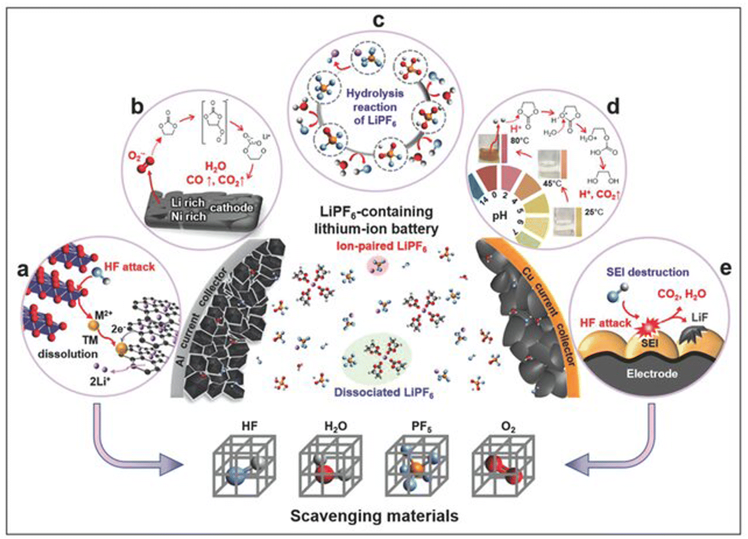 | ||
| Fig. 10 Schematic representation of the key challenges of LiPF6-containing carbonate electrolytes. Reproduced with permission from ref. 217. Copyright Wiley-VCH: (a) transition metal dissolution resulting from HF attack, (b) gas evolution triggered by solvent decomposition, (c) hydrolysis reaction of LiPF6 to form HF and corrosive acids, (d) thermal decomposition of LiPF6, (e) interfacial layer destruction by HF attack. | ||
A seeming solution to mitigate the thermal instability of carbonate electrolytes would be to use alternative, less reactive salts. However, studies have shown that, the solvents themselves are problematic—for instance, Lamb et al.28 showed that EC and DEC were found to produce the most toxic gas during thermal decomposition, with each generating upwards of 1.5 moles of gas per mole of electrolyte without the presence of LiPF6.
Efforts have been made to research the use of alternative Li salts with better thermal stability, conductivity, and less toxicity. To this end, LiTFSI and LiFSI have garnered considerable interest owing to their extremely high thermal stability (i.e., no degradation until ∼360 °C).128 Eshetu et al.218 conducted a detailed investigation of the thermal behavior of LiPF6vs. LiFSI-based carbonate electrolytes. They observed that the LiFSI-based electrolytes produced fewer harmful byproducts, with significantly reduced HF output. However, LiFSI-based electrolytes still emit toxic gases such as SO2, NO, and HCN. Additionally, the calorimetry experiments demonstrated that the LiFSI-based electrolytes have shorter combustion durations, albeit more explosive than the LiPF6-based electrolytes. Sångeland et al.219 investigated the decomposition of a LiTFSI-based carbonate electrolyte (1 M LiTFSI in EC![[thin space (1/6-em)]](https://www.rsc.org/images/entities/char_2009.gif) :DEC 3:7 w/w) and noted ethylene and hydrogen (in negligible quantity) as the dominant volatile organic species formed. Moreover, the application of LiTFSI is hindered by its corrosive reaction with Al foil, which is typically used as the cathodic current collector.128 Therefore, the tradeoffs in the cost and electrolyte properties must be carefully considered when switching from LiPF6 to LiTFSI/LiFSI or other Li salts. Owing to this conundrum, subsequent sections will discuss extensively modern strategies being applied to improve the thermal stability of carbonate electrolytes.
:DEC 3:7 w/w) and noted ethylene and hydrogen (in negligible quantity) as the dominant volatile organic species formed. Moreover, the application of LiTFSI is hindered by its corrosive reaction with Al foil, which is typically used as the cathodic current collector.128 Therefore, the tradeoffs in the cost and electrolyte properties must be carefully considered when switching from LiPF6 to LiTFSI/LiFSI or other Li salts. Owing to this conundrum, subsequent sections will discuss extensively modern strategies being applied to improve the thermal stability of carbonate electrolytes.
 | ||
| Fig. 11 (a) Schematic of the requirements for ether electrolytes for high-voltage LIBs. Reproduced under the terms of the Creative Commons CC-BY 4.0 License.222 Copyright 2024, The Authors. Published by American Chemical Society, and (b) scheme of the autoxidation mechanism of aliphatic ether solvents. Reproduced with permission from ref. 221. Copyright 2012, American Chemical Society. (c) CE test of Li‖Cu cells cycled in an ether solvent (1,1,1-trifluoro-2,3-dimethoxypropane (TFDMP)) containing different salts. Reproduced under the terms of the Creative Commons CC BY license.223 Copyright 2023, The Authors. | ||
As with carbonate electrolytes, the type of Li salt also impacts the thermal/oxidative degradation of ether electrolytes, LiPF6 impedes the performance of ether electrolytes (Fig. 11c). In contrast, LiTFSI or LiFSI can significantly improve the electrochemical performance of Li–metal anodes cycled in ether electrolytes.222 The easily reducible S–F bonds in the anions of LiTFSI and LiFSI salts form electron-insulating compounds such as LiF more readily than those in LiPF6 salt, resulting in the formation of a more stable SEI, translating to better electrochemical performance.222
The concentration of salt in ether-based electrolytes is also paramount. The oxidative stability of ether-based electrolytes at typical Li salt concentrations of ∼1 M is considerably low. This is because, with fewer Li+ available, ether molecules cannot form stable complexes that mitigate oxidation.224 In contrast, carbonate electrolytes have oxygen atoms with lone-pair electrons that can form more stable complexes.224 Consequently, the oxygen atoms in the ethers are more prone to losing electrons, making the electrolyte more susceptible to oxidation and eventual decomposition. The degradation of ether electrolytes is also influenced by the chain length of the ether, where shorter chain ethers tend to be more thermally unstable compared to longer-chain counterparts.225
Moreover, a low glass transition temperature (Tg), high decomposition temperature, and high melting temperature of the polymer matrix form important criteria for selecting a polymeric host, as these significantly affect the thermal behavior of GPEs.142 A low Tg, whilst it enhances the ionic conductivity, can reduce the overall mechanical stability of the electrolyte, leading to an increased risk of thermal decomposition. Below Tg, the polymer exists in a glassy state, and above Tg, the polymer becomes rubbery and more flexible,136 bringing the material closer to melting and decomposition at elevated temperatures. Melting and decomposition of the polymer are typically distinct thermal events, but the thermal energy required for melting can bring the polymer material closer to a state of decomposition, potentially initiating the chemical breakdown of both plasticizer and polymer materials.
The chemical structure of the polymeric host also affects the thermal degradation behavior of GPEs. The varying application cases of LIBs necessitate an electrolyte that is thermally stable over a wide temperature range, making PVDF- and PAN-based GPEs more favored due to their superior thermal stability. This stability is attributed to the strong C–F bonds in PVDF142 and the formation of a stable, cross-linked structure in PAN upon heating.143 Conversely, GPEs based on polymers such as polyethylene glycol diacrylate (PEGDA) are PEO (and their derivates) are highly flammable.226 Owing to this, fire retardants, such as organic phosphates like trimethyl phosphate (TMP), triethyl phosphate (TEP), and dimethyl methylphosphate (DMMP), have been employed to address the flammability issue.226,227
GPEs offer considerable advantages over carbonate- and ether-based electrolytes. However, their thermal instability still poses a major challenge that must be addressed to ensure safe and reliable applications. Hence, strategies to improve and enhance the safety of GPEs will be comprehensively discussed in Section 4.
3. Cell and pack level studies on understanding and mitigating thermal runaway risk
a. Battery abuse testing methods and mechanisms
Batteries are subjected to a wide variety of stresses when operating in various applications, including mechanical vibrations and impact, high electrical load, and extreme thermal environment. These stresses can result in accelerated degradation, gas generation, excessive swelling, internal short circuits, overheating, and gas venting, leading to thermal runaway. To fully understand and mitigate the effects of thermal runaway, abuse testing and simulations are typically performed on battery cells. In this section widely employed mechanical, electrical, and thermal abuse testing methods are discussed.650 cells, providing comprehensive data on the thermal and structural dynamics. The variability of nail penetration position was found to directly affect the temperature rise and the failure mechanism of the cells.229 Another study developed a new method for nail penetration analysis using small, slow, and in situ sensing, referred to as 3S.230 In the study, a small nail (diameter ∼1 mm) embedded with a micro temperature sensor at the tip was used for the nail penetration test on a 3 A h pouch cell at penetration speeds of <0.1 mm s−1 (Fig. 12). The study observed that the in situ sensed nail tip temperature reached a maximum of over 800 °C while the surface temperature only reached about 400 °C during thermal runaway. Specifically, in situ monitoring helped observe three temperature peaks before it's onset which could not be detected from surface temperature indicating that the in situ sensing can reveal critical early-stage indicators of the thermal runaway phenomena, such as intense local hot spots and precursory thermal spikes. These temperature peaks were due to the contact between the nail tip and the current collector as a result of nail piercing through the battery in a controlled manner. This contact created a low resistance internal short circuit that induced high internal short circuit current and rapid heat generation, ultimately leading to a sudden temperature rise. A rapid decrease in the temperature was also noted following each peak. This was attributed to the rupturing of the Al foil that led to the increase in contact resistance, decreasing the local current and heat generation at the site of penetration.230
 | ||
| Fig. 12 (a) Schematic of the small, slow, and in situ sensing (3S) nail penetration test. (b) Photograph of the small, in situ sensing nail. Reproduced under the terms of the Creative Commons CC BY license.230 Copyright 2020, The Author(s). | ||
This method separates internal short-circuit processes from thermal runaway. Yang et al.231 studied the evolution in voltage, temperature, and vent gas of 8 types of cylindrical batteries using LFP cathode chemistry. It was observed that the onset was triggered by the shrinkage of the separator and the reactions between the cathode and electrolyte. It was also found that the runaway reactions were more intense when penetration was performed near the cell ends, but the nail speed had virtually no effect on the thermal and electrochemical behavior of the cell.
Chiu et al.232 simulated the electrochemical-thermal behavior of a punctured 5.25 A h cell. The model predicted a rapid increase in current density due to an internal short circuit at the site of nail penetration. However, as the active material was depleted, the current density predicted by the model declined. Zhao et al.233 introduced an area-specific contact resistance to model Joule heating at the location of penetration. Their coupled electrochemical-thermal model successfully predicted the rapid temperature rise during nail penetration with current and voltage responses, and deformation of the battery. The model prediction was verified using experimental results.
793 s and 5332 s, respectively, as the rate increased from 0.5C to 3C. For the LFP batteries, the time decreased by 1812 s when the rate was increased from 1C to 3C.
Huang et al.239 experimentally investigated the internal failure mechanisms and associated external characteristics during overcharging in prismatic and pouch cells using Li[Ni0.33Co0.33Mn0.33]O2/Gr pouch and prismatic cells. The cells were charged from 0% SOC to the set end point at 1C current. During stage I (safe overcharge stage), both pouch and prismatic cells maintained low temperatures, but the pouch cells exhibited better overcharge tolerance. As overcharging progressed, the prismatic cell experienced a slower rise in temperature and deformation due to its safety valve. The maximum surface temperature difference increased linearly during the test, with hotspots forming at one end of both cells, offering insights for improved design for effective heat dissipation. Ye et al.240 investigated the dynamic thermal behaviors of commercial LiCoO2 + Li(Ni0.5Co0.2Mn0.3)O2/C + SiOx cells during overcharge under adiabatic conditions by combining a multi-channel battery cycler with an accelerated rate calorimeter (ARC).
The study found that the overcharge process in LIBs follows four distinct stages, as shown in Fig. 13. (1) A to B: as the cathode delithiated and the anode lithiated, the voltage increased gradually, with low surface temperature and minimal gas evolution until decomposition accelerated above 4.5 V. (2) B to C: as the cathode approached full charge, heat generation increased due to electrolyte decomposition, producing CH4 and alkyl radicals, while gas release caused cell deformation, leading to Li plating on the edges of the graphite anode due to a change in the distance between the anode and cathode. (3) C to D: the surface temperature increased sharply above 60 °C, triggering exothermic reactions between the delithiated cathode and electrolyte, causing CO2 gas evolution, voltage drop, and structural degradation of the cathode. (4) D to terminal: when the internal temperature reached 150–160 °C, the separator shut down, leading to violent reactions involving Li, electrolyte, binder, and cathode material. This triggered thermal runaway, rupture, and gas emissions (CO2, CO, H2, CH4, C2H6, C2H4). At higher C rates (>1.0C), overpotential heat accelerated temperature rise, making electrolyte–cathode reactions more intense before Stage B.
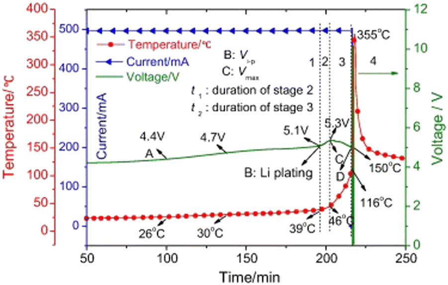 | ||
| Fig. 13 Stages of overcharge induced thermal runaway based on overcharging experiments combined with ARC. Reproduced with permission from ref. 240. Copyright 2016, Elsevier Ltd. | ||
Zhu et al.241 systematically studied the overcharge-induced thermal runaway properties of 30 A h cells using NCM622 cathode at different C rates at 30 °C. It was found that the overcharge process consisted of four stages. Stage I entailed normal charging with stable voltage and temperature, while Stage II marked the beginning of the overcharge conditions, causing a gradual voltage increase and slight temperature increase. In Stage III, voltage plateaus and temperature increased rapidly, signaling an increased risk that escalates in Stage IV, where extreme temperature spikes led to battery rupture, fire, or explosion, accompanied by a sharp voltage drop. Qi et al.242 developed an overcharge model of the LIB pack by coupling the electrochemical model with the thermal abuse model. The study used a battery pack of three fully charged batteries with a capacity of 10 A h, with only the middle one overcharged. It was found that higher overcharge currents increased the thermal runaway onset temperature of the overcharged middle cell but lowered it in the adjacent non-overcharged cells. Cell spacing and clamping significantly influenced heat transfer, increasing the risk of failure in neighboring cells. The overcharged middle cell heated rapidly, transferring heat to adjacent cells.
Using both experimental and numerical methods, Mei et al.243 demonstrated that overcharging of a commercial 26650 LiNi1/3Co1/3Mn1/3/Gr cell caused Li plating. The overcharge tests performed to induce Li plating included constant current charging at 0.2C and 0.5C to the cut-off voltage range of 4.5–4.9 V with no relaxation to stabilize the Li content within the electrode bulk. They found that Li plating begins at voltages >4.5 V, with greater Li deposition occurring at higher voltages as confirmed by SEM images showing dendritic Li growth at the anode-separator interface. Furthermore, using computational simulations, they revealed that overcharge led to deeper Li penetration, increasing plating severity. The model showed a linear relationship between Li plating and C rates, indicating that higher C-rates accelerate plating, emphasizing the need for controlled charging. Increasing anode thickness while maintaining a reasonable N/P ratio (i.e., 1.1–1.2) was found to reduce Li plating risk by lowering local current density and increasing Li accommodation in the electrode structure.
Liu et al.246 developed a 3D equivalent circuit model of a 20 A h LIB and performed ISC simulations. The study considered the effects of ISC area, resistance, penetration depth, convective heat transfer coefficient, and ISC position on thermal runaway. The results of the study demonstrated that the average cell temperature is only weakly affected by the ISC area, penetration depth, and position. On the other hand, the ISC resistance and the convective heat transfer coefficient have large impacts on the thermal runaway propagation. A high convective heat transfer coefficient can effectively suppress this propagation. However, such a high convective heat transfer coefficient is hard to achieve at the cell surface. Finegan et al.247 used an ISC device placed in multiple locations across the cell for controlled, on-demand, initiation of thermal runaway to study the nucleation and propagation failure within 18650 cells through the use of high-speed X ray imaging at 2000 frames per second. It was observed that sidewall rupture was more likely when the runaway event was initiated closer to the casing of the cell. Likewise, the cylindrical mandrel in the core of the electrode assembly was shown to influence the venting process.
Huang et al.248 reported in situ measurement of temperature distributions in a 2.5 A h pouch format cell during ISC and thermal runaway events. The events were triggered by nail penetration. It was observed that the in situ sensed nail tip temperature started to increase after 30 s and exhibited multiple peaks corresponding to the cell voltage drops. The multiple temperature peaks and voltage drops suggested that there were multiple short-circuit processes during the nail penetration process. The highest temperature of the nail tip at the internal short circuit location was measured to be 209 °C. Liu et al.249 compared the performance of five substitute triggering methods for ISC; use of phase change materials (PCM), shape memory alloys (SMA), artificially induced dendrite growth, equivalent resistance, and nail penetration. Likewise, the thermal-electrical coupled features, controllability, similarity to real accidents, and repeatability of the test were discussed by experimental and modeling analysis. It was found that there were four different classes of ISC. The first class was the most dangerous, where the voltage rapidly drops to 0 V and has a maximum temperature rising rate of nearly 100 °C s−1. This class of ISC would be accompanied by severe thermal runaway when conducted by nail penetration or triggering Al-An type ISC by PCM and SMA. The second and third class featured less abrupt voltage failure and slow voltage drop, respectively, and both these classes demonstrated lower temperature rise of only 10 °C s−1 with no thermal runaway. The fourth class showed minimal impact in both voltage drop and temperature rise.
Xu et al.250 employed an electrochemical-thermal model, validated through experiments, to analyze how electrode design parameters influence ISCs in cylindrical LIBs. A parametric study examined the effect of parameters such as porosity, electrode/separator thickness, short-circuit area, and failure layers, revealing their effects on internal resistance, voltage drop, and temperature rise. Additionally, the study categorized different short-circuit types (An–Ca, An–Al, Ca–Cu, and Al–Cu) to enhance understanding of failure mechanisms and provide insights for safer battery designs. The study validated a coupled electrochemical-thermal model by comparing simulation results with experimental data, effectively describing electrochemical behavior during normal and short-circuit conditions. Using a 2200 mA h LCO cell, experiments, including nail penetration tests, showed that voltage remained stable until 4 mm penetration, after which temperature and voltage changed significantly. Thermal runaway occurred 300 seconds after short-circuit initiation, though model predictions deviated from measured temperatures at this stage. The study found that cathode design had a more substantial impact on internal resistance and battery safety than the anode, emphasizing the importance of optimizing cathode electrode architecture. These insights provide crucial guidance for safer LIBs designs, focusing on separator integrity, porosity, and thickness to mitigate short-circuit risks.
 | ||
| Fig. 14 Discharge capacity at different C rates. Reproduced with permission from ref. 251. Copyright 2022, Elsevier Ltd. | ||
Zeng et al.252 investigated the ESC characteristics of 18650-type NCM LIBs under different SOCs and short-circuit currents. The study involved ultra-high discharge rates (i.e., 15C, 18C, 20C, 22C, 25C) for constant current discharge at 50% and 100% initial SOCs to simulate the ESC condition. The results of the study found that short circuits induced a serious risk of deleterious thermal events when the discharge rate reached 25C and the maximum temperature exceeded 500 °C. At low SOC levels, there was rapid depletion of Li+, increasing the polarization resistance and exhibiting a sharp voltage drop in this instance. The high temperature during the short circuit induced a closure of the separator pores.
An et al.253 further studied the effect of SOC and discharge rate on the ESC behavior of a 3 A h LFP graphite pouch battery. The battery damage was triggered by ESC abuse for 50% and 100% initial SOCs at discharge rates of 20C, 30C, 40C, and 50C. The results of the study indicated that maximum temperature points during ESC were always found halfway between the anode and cathode tabs for all discharge rates. Electrolyte depletion and thermal adhesion of the cathode to the electrode and wrinkling of the electrode were observed due to gas generation from heat-driven side reactions. In another study,254 an analytical model to predict runaway events in prismatic and pouch cells due to ESC/ultra-high discharge rates was developed. COMSOL Multiphysics was used for validation of the analytical model, and it was found that at discharge rates above 15C, multiple decomposition reactions occur, ultimately leading to thermal runaway. The ambient temperature was also found to have a critical role, as cells discharged below 30 °C remain stable, while those at 40 °C or higher experienced a higher runaway risk due to reduced convective heat dissipation, causing excessive temperature rise. At a 15C discharge rate, only SEI decomposition occurs, generating insufficient heat to trigger further reactions. However, at a higher discharge rate of 18C, additional reactions, including negative electrode and solvent decomposition, occur, generating enough heat to initiate a chain reaction. This escalation leads to a rapid rise in temperature.
b. Characterizing thermal stability of battery materials and cells using calorimetry
Various calorimetric tests are used to understand the behavior of LIBs during thermal abuse conditions. In these tests, batteries are typically heated in adiabatic conditions, and temperature, pressure, and their rate of increase are measured.255 Differential scale calorimetry (DSC) is employed to look at the thermal stability and exothermic reactions of chemical components in a battery at the material level.255 ARC is designed to study exothermic chemical reactions by simulating adiabatic conditions. By employing ARC, critical kinetic parameters, i.e., the onset temperature of the reaction and the enthalpy of the exothermic process, can be acquired.256Liu et al.257 performed an ARC test on an aged 1.2 A h pouch cell with 95% LiMn2O4 + 5% Li(Ni0.5Mn0.2Co0.3)O2 cathode and graphite anode to obtain the onset temperature of the SEI decomposition reaction. Ren et al.258 investigated the thermal runaway mechanisms using DSC for a fully charged 24 A h Li(Ni1/3Co1/3Mn1/3)O2/graphite battery. The cell components extracted from the pouch cell were tested individually and as mixtures to elucidate the mechanism and characterize exothermic reactions. Six exothermic reactions were characterized, and kinetic analysis was performance on them based on the DSC data. It was found that the heat generation was dominated by the reactions on the anode/electrolyte interface, such as the decomposition of SEI film and the reaction between anode active material and electrolyte. The data from the ARC test was used to validate the model prediction once all the kinetic parameters were estimated using this data. Patel et al.259 used ARC test to study the failure mechanism of commercially available 18650 cells with Li(Ni0.6Mn0.2Co0.2)O2 cathode, polymer separator, and graphite anode. The study revealed the initial exothermic event occurred between 30–50 °C and is attributed to the breakdown and reformation of the SEI layer while the second exothermic event indicating the onset of thermal runaway occurred at 175 °C. The study also quantifies the reaction rates associated with thermal failure.
Kvasha et al.260 studied the thermal runaway of three different Li-ion cells (NCA/graphite, LFP/graphite, NCA/LTO) at 100%, 50%, and 9% SOC and conducted DSC and ARC tests to study the behavior of positive and negative electrodes at the three SOC levels. All cells underwent thermal runaway, regardless of SOC or chemistry, with higher SOC leading to lower onset temperatures and faster self-heating rates. Despite using a low-stability polyolefin separator, LFP/graphite was the most thermally stable due to its polyanionic structure, unlike the unstable NCA, which releases oxygen when heated. DSC tests confirmed that all electrodes were thermally unstable in LP30 electrolyte.
In a study by Feng et al.,261 the DSC tests showed significantly lower heat generation in NCM cells compared to ARC, suggesting that anode reactions were not the primary heat source during thermal runaway. Instead, the process was mainly driven by redox reactions between the cathode and anode, with the cathode undergoing active material decomposition, cathode–electrolyte reactions, and electrolyte breakdown, while the anode experienced SEI layer decomposition and Li–electrolyte interactions. The ARC tests identified three key temperatures: T1 (70–150 °C) for SEI decomposition, T2 (<300 °C) as the thermal stability threshold, and T3, which varied with energy density and determined spread rate. These findings highlight that thermal runaway is primarily dictated by cathode-driven exothermic reactions and battery design factors rather than internal short circuits. Yuan et al.262 conducted experiments with different Li-ion cells in sealed canisters of steel and used DSC to analyze small samples of anodes, cathodes, and separators while ARC was used to heat battery cells. Cells were charged and discharged three times and were charged again to 100% SOC for testing, and each test was repeated twice to ensure reliability and repeatability. Three different cathode chemistries were selected for the study, namely NCM, LFP, and LTO. For the NCM cell, it was found from the DSC tests that anodes and cathodes exhibited sharp exothermic peaks at lower temperatures (159–174 °C for anodes, 125–200 °C for cathodes), which indicated lower stability as compared to LFP and LTO batteries. Likewise, ARC tests showed that NCM cells had a slower temperature rise before experiencing the highest peak temperature (998 °C), while LTO had the lowest peak temperature of 305 °C but had faster thermal runaway (Fig. 15). It was observed that NCM cells emitted flames while LFP cells only released smoke, indicating different behaviors at thermal failure among different chemistries.
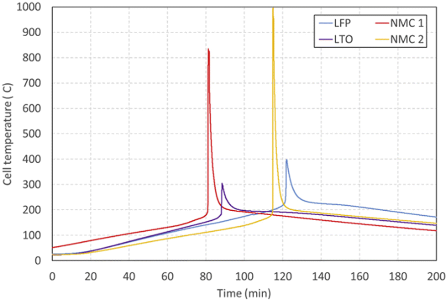 | ||
| Fig. 15 Comparison of surface temperatures during ARC tests. Reproduced with permission from ref. 262. Copyright 2020, Elsevier B.V. | ||
Fractional Thermal Runaway Calorimetry (FTRC) is also used to measure thermal runaway behavior by characterizing energy release during thermal events. FTRC measures the total heat release and fractionates it into heat emitted through the casing and heat expelled as ejecta, providing a detailed energy distribution analysis. Unlike DSC, which analyzes small material samples for heat flow and reaction enthalpies, and ARC, which evaluates whole cells under adiabatic conditions to measure self-heating rates, FTRC uniquely quantifies how heat propagates externally, making it essential for studying thermal management and containment strategies in real-world applications. Walker et al.263 employed FTRC for GS Yuasa Li-ion cells and found the average total energy release to be 1.6 times the stored electrochemical energy, supporting the notion that energy yield scales linearly with the capacity of the cell.
c. Cell gas build up and venting
During thermal runaway, LIBs generate flammable and toxic gases, leading to internal pressure build-up and eventual venting to prevent catastrophic failure. Several studies have investigated the composition and behavior of vented gases using techniques like gas chromatography and Fourier transform infrared spectrometry to identify key species, such as hydrogen, carbon monoxide, methane, and ethylene. These studies provide crucial insights into gas generation mechanisms, venting thresholds, and the impact of factors like SOC and cell chemistry. Understanding these processes is essential for improving battery safety, fire mitigation strategies, and thermal management systems and as such there have been numerous studies on quantifying and understanding the gas venting process during thermal runaway in batteries. Yuan et al.262 conducted gas chromatography to study the vented gas and found that major gas concentrations of vented gases were primarily dependent on the battery chemistry used. The study used three different chemistries, namely NCM, LFP, and LTO, and found that the NCM cells produced the highest levels of CO and CH4 but the lowest levels of C2H4 while LFP cells produced the highest levels of H2, C2H2, C2H4, and C2H6 but lowest levels of CO. On the other hand, LTO cells produced the highest levels of CO2 and lowest levels of H2, CH4, C2H2. Jiaqiang et al.264 used gas chromatography to review models of gas generation, highlighting its role in increasing internal battery pressure. Their study found that flammable and toxic gases, including CO2, H2, CH4, and C2H6, were released, with their composition varying based on cathode materials and operating conditions. They also outlined the importance of understanding these mechanisms as crucial for assessing hazards. Using a H2 detector and Fourier transform infrared spectroscopy in their study, Jia et al.265 also found similar composition but reported differences in total gas production depending on whether thermal runaway is caused by overcharging or overheating. The overheating scenario involved larger gas production (101.3 L) suggesting a high reaction rate as compared to overcharging, which produced a gas volume of 62.1 L only. This study also identified that overcharging promotes gas release, leading to earlier venting mechanism activation by triggering the safety venting mechanism. Despite overcharging producing a lower volume of gas, it led to faster thermal runaway onset than overheating by initiating earlier gas generation that resulted in weakening of the structural integrity of the cell and triggering an internal short circuit. On the other hand, during overheating, the battery underwent progressive degradation that required a higher temperature threshold before thermal runaway was initiated, but it was more intense when it occurred. Ostanek et al.266 developed and validated a gas generation model that computes gas generation from decomposition reactions and electrolyte vaporization. Their results indicated that modification of cell design and geometry could influence the evaporation rate, which in turn affected the vent time and time to thermal runway. Kim et al.267 developed a numerical model to study cell venting, internal pressure, and gas-phase dynamics behavior of 18650 Li-ion cells. It was found that the production of flammable gases like CO, H2, and hydrocarbons led to higher internal pressure with an increase in SOC. Mao et al.268 found a simplified relation suggesting that the gas generation rate is proportional to the temperature increase rate. They also found the peak pressure at 100% SOC to be significantly higher than at 0% SOC.
4. Approaches to enhancing safety
a. Cathode
Several strategies have been proposed to address the degradation mechanisms of the LIB cathode materials. These strategies include modifying the microstructure using techniques, such as concentration gradient design and nanorod synthesis, and applying protective coatings.a. Concentration gradient cathodes. Concentration gradient cathodes are engineered to enhance performance, safety, and longevity by incorporating a deliberate variation in chemical composition from the core to the shell of the cathode material. Three main configurations have been developed based on this gradient concept: core–shell gradient (CSG), full-concentration gradient (FCG), and two-sloped full-concentration gradient (TSFCG) cathodes.269–271 This approach provides significantly enhanced cycling stability and thermal resilience, especially under strenuous high voltage cycling conditions. For Ni-rich layered oxide, these materials feature a high concentration of Ni at the core of the cathode and a Mn-rich concentration at the shell to serve as a protective layer that reduces the reactivity at the cathode's surface (Fig. 16a).41,272,273 Sun et al.273 first introduced the concept of a concentration-gradient cathode in 2010 with the development of Li[Ni0.72Co0.18Mn0.10]O2, a Ni-rich layered oxide designed to enhance both electrochemical and thermal stability. This cathode featured a Ni-rich core (Li[Ni0.8Co0.2]O2) surrounded by a Mn-rich shell (Li[Ni0.55Co0.15Mn0.30]O2) (Fig. 16b), creating a gradual compositional transition that mitigated structural degradation and improved cycling performance. The cathode delivered an initial discharge capacity of 193 mA h g−1 and exhibited excellent cycle stability, retaining 95.3% of its capacity after 50 cycles, compared to only 66% retention for the core material alone. Thermal analysis further revealed that the exothermic decomposition peak shifted from 225 °C to 280 °C, reducing heat generation and improving safety. In 2011, this was refined with the design of Li[Ni0.83Co0.07Mn0.10]O2, incorporating a Ni-rich core (Li[Ni0.9Co0.05Mn0.05]O2) and a Ni-depleted shell (Li[Ni0.68Co0.12Mn0.20]O2). This modification increased capacity to 200 mA h g−1, with 96.9% retention after 50 cycles, compared to 79.2% for the core material alone. Thermal stability also improved, as the exothermic peak shifted to 227 °C.272
 | ||
| Fig. 16 (a) Illustration of core–shell, core–shell concentration gradient, and full concentration gradient NCM particle structures. Reproduced with permission from ref. 274. Copyright 2023, Elsevier Ltd. (b) SEM images of the lithiated core–shell oxide with concentration-gradient shell particles. Reproduced with permission from ref. 273. Copyright 2010, Wiley-VCH Verlag GmbH & Co. KGaA, Weinheim. (c) Capacity retention, thermal stability versus specific capacity of gradient cathodes compared to constant concentration cathodes. Reproduced with permission from ref. 275. Copyright 2017, American Chemical Society (d) cross-sectional SEM images of the three Li-rich layered oxides (S1, S2, and S3) with different gradients and (e) gradients of representative S1, S2, and S3 semispheres as reflected by the contents of transition metals at positions 1–7 (see Fig. d) from the sphere center to the surface. Reproduced with permission from ref. 276. Copyright 2020, Wiley-VCH GmbH. (f) The comparison of cycling stability for the raw LiMn2O4 and obtained g-Li1+xMn2−xO4. Reproduced with permission from ref. 277. Copyright 2022, Elsevier B.V. | ||
Building on this in 2012, they later introduced the FCG cathode, LiNi0.75Co0.10Mn0.15O2, optimizing metal distribution to achieve 215 mA h g−1 and 90% retention after 1000 cycles. The exothermic reaction was further delayed to 250 °C, significantly reducing thermal risks.278 This progression from core–shell (2010) to gradient (2011) to fully optimized FCG (2012) established a clear pathway for developing high-energy, long-life cathodes suited for EVs and grid storage applications. Noh et al.279 further highlighted the superior performance of FCG nanorod-structured Li[Ni0.54Co0.16Mn0.30]O2 cathode material compared to conventional cathode materials Li[Ni0.5Co0.2Mn0.3]O2 (NCM523) and Li[Ni0.33Co0.33Mn0.33]O2 (NCM333). The FCG exhibited an initial discharge capacity of 183.7 mA h g−1, outperforming the conventional constant composition NCM523 at 174.9 mA h g−1 and NCM333 at 162.5 mA h g−1. After 100 cycles, the FCG material retained 93.2% of its capacity, compared to 89.9% for NCM523 and 92.4% for NCM333. At −20 °C, the FCG also showed higher capacity retention, confirming its superior electrochemical stability and cycling performance. Chong et al.280 demonstrated that gradient cathodes consistently achieve high discharge capacities (Fig. 16c), exceeding 200 mA h g−1 across multiple configurations.
The compositional gradient, particularly in TSFCG85, also resulted in superior cycling stability, with over 90% capacity retention after 100 cycles. Concentration gradient strategies, while widely used in Ni-rich layered cathodes, are also applied to Li-rich layered oxides and 5 V spinel cathodes. Wu et al.276 designed a Li-rich layered oxides with an FCG structure to enhance its electrochemical performance. By creating Li-rich layered oxide particles with a core-to-surface gradient, featuring a decrease in Mn and an increase in Ni and Co concentrations (Fig. 16d and e), they addressed common issues such as voltage decay and poor cycling stability. The gradient-tailored Li-rich layered oxides achieved 88.4% capacity retention after 200 cycles at 200 mA g−1, with an average voltage decay of just 0.8 mV per cycle. Additionally, thermal stability was improved, with a 41% reduction in heat release rate. This study demonstrated that the FCG design effectively suppresses voltage decay and enhances both cycling and thermal stability, making it a promising approach for Li-rich cathode materials. Similarly, Cheng et al.281 investigated the synthesis and electrochemical performance of Li-rich Mn-based oxides with a concentration-gradient structure to improve cycling retention. They employed a co-precipitation and sol–gel method to create a CSG structure, where Mn0.75Ni0.25C2O4 was used as the core and Li1.2Mn0.54Ni0.13Co0.13O2 as the shell. The CSG cathode demonstrated significant improvements in cycling stability, achieving 95.4% capacity retention after 100 cycles at 1C, and the initial Coulombic efficiency increased by 12% to 85%. Structural analysis indicated that the concentration-gradient design reduced Li/Ni mixing and improved Li+ diffusion, contributing to enhanced electrochemical performance and long-term stability.
For 5 V spinel cathodes, Zhang et al.277 developed a gradient Li1+xMn2−xO4 structure to enhance cycling stability in LIBs. The gradient-Li1+xMn2−xO4 exhibited a stable capacity of ∼105 mA h g−1 over 250 cycles with over 99% Coulombic efficiency, outperforming raw LiMn2O4, whose capacity dropped from ∼120 mA h g−1 to 76 mA h g−1. The gradient design, with a Li-rich surface, mitigated Mn dissolution and the Jahn–Teller distortion, significantly improving capacity retention and stability compared to homogeneous doping. Although concentration gradient strategies provide enhanced stability by tailoring the chemical composition from the core to the surface, another effective structural modification lies in reshaping primary particles into nanorod structures.
b. Nanorod cathode structures. This approach entails reshaping the primary particles into tightly packed elongated rod-like structures that are oriented radially. The elongated structure of the nanorods promotes Li+ movement by aligning the Li-containing (003) planes outwardly to provide a straight, shortest pathways for Li+ diffusion (Fig. 17a and b). It also allows for homogenous tensile stress dissipation, allowing for better absorption of the anisotropic lattice strain caused during phase transition. As a result, the microcrack degradation pathway is suppressed during prolonged cycling, preventing capacity fading and impedance increase from electrolyte penetration (Fig. 17c).41,282,283 These nanorod structures, also observed in gradient-structured cathode materials, have been shown to outperform their constant concentration counterparts as highlighted by Sun et al.,284 where the Li[Ni0.81Co0.06Mn0.13]O2 nanorod gradient cathode (NRG81), delivered a discharge capacity of 225 mA h g−1 with 91% capacity retention over 100 cycles in half cells. In full cell tests, NRG81 retained 88.3% capacity after 1000 cycles, whereas its counterpart without nanorod (CC82), only retained 55.9% (Fig. 17d). Thermal stability tests performed on both cathode materials also showed that the NRG81 delayed the transition to the rock-salt phase until 390 °C compared to 320 °C for (CC82), demonstrating its improved safety under high-temperature conditions. As indicated by Noh et al.,285 these rod-shaped particles grow radially from the center of the particle and extend to lengths of up to 2.5 μm. These elongated primary particles are arranged in a crystallographic texture that aligns their c-axis in the transverse direction, which is crucial for improving Li+ diffusion and enhancing electrochemical kinetics. This unique nanorod structure significantly contributes to the material's high-rate capability, low-temperature performance, and thermal stability.
 | ||
| Fig. 17 (a) TEM image of the NCSb89 grains showing the Li diffusion channels (b) HR-TEM image of the circled region in (a). Reproduced with permission from ref. 286. Copyright 2020, American Chemical Society. (c) Morphological design of nanorod cathode (top) preventing electrolyte penetration, and typical cathode (bottom) failing to prevent electrolyte penetration during charging. Reproduced under the terms of the Creative Commons CC-BY-NC-ND license.41 Copyright 2020, American Chemical Society. (d) Comparison of long-term cycling (1000 cycles) performances of NRG81 vs. CC82 in pouch-type full-cells at 1.0C cycling rate. Reproduced with permission from ref. 284. Copyright 2019, American Chemical Society. (e) a-Axis lattice parameters. (f) c-Axis lattice parameters and (g) summaries of the capacity retention values after 1000 cycles as functions of average angle of primary particle, aspect ratio, and grain size. Reproduced with permission from ref. 287. Copyright 2021, The Authors. | ||
Although nanorod-structured cathodes are characteristic of concentration gradient cathodes, they can be synthesized through doping uniform composition cathodes with high oxidation dopants. These dopants influence the crystal growth process by altering nucleation and growth kinetics, which leads to anisotropic crystal growth and the formation of elongated nanorods rather than conventional polyhedral morphologies.287–289 Sun et al.286 explored the stabilization of a highly Ni-rich cathode, Li[Ni0.89Co0.10Sb0.01]O2 (NCSb89), using a flower-petal nanograin structure. This alignment improved Li+ diffusion and reduced the harmful effects of the H2 → H3 phase transition. NCSb89 retained 95.0% of its capacity after 100 cycles in half-cells and 83.9% after 1000 cycles in full cells. It also delayed the rock-salt phase transition until 390 °C, compared to 320 °C for the undoped material. The dense nanograins minimized microcracks and electrolyte seepage, enhancing both cycling performance and safety. To further understand the role of high-oxidation-state dopants in stabilizing Ni-rich layered cathodes, Sun et al.290 studied Mg2+, Al3+, Ti4+, Ta5+, and Mo6+ in Li[Ni0.91Co0.09]O2 (NC90). Ta5+ and Mo6+ significantly improved cycling stability, with pouch-type full cells retaining 81.5% capacity after 3000 cycles at 200 mA g−1. The dopants induced a nanorod grain structure, reducing microcracks and electrolyte infiltration. These dopants also enhanced Li/TM cation ordering, stabilizing the layered structure and suppressing the H2 → H3 phase transition. Charge-transfer resistance remained lower over 100 cycles, improving Li-ion transport. The study established a direct correlation between oxidation state, particle morphology, and electrochemical performance (Fig. 17e–g), offering a strategy to enhance cycle life and thermal stability in high-Ni cathodes.
Overall, nanorod structures contribute to a safer battery system by minimizing the formation and propagation of microcracks. The homogenous stress distribution and reduced impedance growth further enhance thermal stability, making nanorod cathodes a safer option for high-performance LIBs.
Li-rich layered oxide cathodes can also be synthesized into nanorods with improved rate capability and enhanced material utilization stemming from shorter electron and ion transport pathways. Chen et al.291 synthesized porous Li-rich oxide nanorods, Li[Li0.19Mn0.32Co0.49]O2. The nanorods, with diameters of ∼200 nm and composed of 20 nm subunit particles, featured a hierarchical porous structure that significantly enhanced electrochemical performance. These nanorods delivered a discharge capacity of 267 mA h g−1 at 0.2C and retained a capacity of 145.4 mA h g−1 at 5C, demonstrating improved rate capability.
a. Fluoride-coated cathodes. Fluoride-coating has emerged as a promising strategy to mitigate surface degradation in cathode materials. By forming a stable protective layer on the cathode surface, fluorine minimizes side reactions with the electrolyte, reduces transition metal dissolution, and enhances the overall electrochemical stability. Fluoride compounds are generally chemically inert and are not easily reduced or oxidized during cycling conditions. The introduction of F− has been shown to improve the rate performance and cycling stability of LIB cathodes, while also lowering charge transfer resistance. The high electronegativity of fluoride ions facilitates the formation of LiF, which enhances the interfacial stability of cathode materials.298–300
i. Ni-rich layered oxide cathode. In Ni-rich layered cathode, these coatings serve as HF passivating layers that reduce the acidity of non-aqueous electrolytes on the cathode surface and suppress metal dissolution from the cathode materials. They act as a physical protection layer that protects the cathode surface from HF attack and electrolyte decomposition (Fig. 18a).301 Lee et al.302 investigated the impact of an AlF3 coating on the long-term cycling performance of Li[Ni0.8Co0.15Al0.05]O2 cathodes. Using a dry coating process, they applied a 50 nm AlF3 layer to the cathode surface. The AlF3-coated cathodes exhibited improved electrochemical performance, particularly at elevated temperatures. At 55 °C, the coated cathode demonstrated capacity retention of 84.7% after 100 cycles, compared to 79.1% for the uncoated version. In long-term cycling tests at room temperature, the coated cathode maintained 86.2% of its capacity after 1000 cycles, while the uncoated sample retained only 66.5%. This improvement was attributed to the AlF3 layer's ability to suppress TM dissolution, reduce charge transfer resistance, and prevent particle pulverization during cycling (Fig. 18b–e), ultimately enhancing the cathode's structural stability and thermal safety. Xie et al.303 investigated the effects of 10 different fluoride coatings on the cycling stability of high-voltage LiNi0.5Co0.2Mn0.3O2 (NCM523) cathodes, focusing on mitigating interfacial reactions between the cathode and electrolyte. They found that AlF3-coated NCM523 showed the best performance, retaining 88% of its capacity after 200 cycles at 4.5 V, compared to 56% for the uncoated sample. The 2.7 nm AlF3 coating effectively suppressed interfacial reactions and maintained structural stability. Other fluorides, such as YF3 and ZrF4, also improved performance, but to a lesser extent. The result showed that coatings with a suspension pH near 4.0 and small cation ionic radii provide strong protection, with AlF3 being particularly effective in enhancing the longevity of NCM523 cathodes. Wang et al.304 developed a solvothermal method using trifluoroethanol to in situ construct a uniform fluoride coating layer on Ni-rich LiNi0.83Co0.12Mn0.05O2 (NCM) cathode materials. The fluoride coating significantly enhanced the chemical stability of NCM against air and reduced side reactions between the cathode and the electrolyte. After four weeks of air aging, the fluoride-coated NCM (NCM-F) maintained a high initial capacity of 166.96 mA h g−1 compared to 105.65 mA h g−1 for the uncoated NCM, with a much lower voltage polarization. The NCM-F retained 84.91% capacity after 200 cycles compared to 61.32% for the uncoated sample. In a recent work by Ryu et al.,305 fluorine coating significantly improved the stability of Ni-rich layered cathode Li[Ni0.9Co0.05Mn0.045Nb0.005]O2 (Nb-CSG90). The F–Co-washed cathode retained 65% capacity after 6000 cycles, compared to 55.2% for unwashed and 63.7% for DI-washed cathodes. In pouch-type full cells, capacity retention after 1000 cycles reached 93% for F–Co-washed cathode, outperforming 87.1% for F-coated-only and 85.6% for Co-washed-only cathode. Gas evolution at 60 °C storage was also substantially reduced, lowering battery swelling and enhancing safety. XPS analysis confirmed LiF formation, which suppressed electrolyte decomposition and HF attack, while EIS measurements showed lower resistance growth, ensuring stable Li-ion transport over prolonged cycling.
 | ||
| Fig. 18 (a) Schematic drawing of the interface between the cathode and electrolyte. Reproduced from ref. 301. Copyright 2016, American Chemical Society. TEM bright-field images of (b) the pristine Li[Ni0.8Co0.15Al0.05]O2. (c) Magnified images of (b). (d) The AlF3-coated Li[Ni0.8Co0.15Al0.05]O2, and (e) magnified images of (d) after 500 cycles at 55 °C. Reproduced with permission from ref. 302. Copyright 2013, Elsevier B.V. (f) Cycling performance of uncoated and AlF3 coated Li-rich Mn-rich layered oxide (Li1.2Ni0.15Co0.10Mn0.55O2) and (g) schematics of the microstructural changes of uncoated and AlF3-coated Li-rich Mn-rich. Reproduced with permission from ref. 306. Copyright 2014, American Chemical Society. (h) Schematic of on AlF coating on LNMO surface, (i) TEM images of 1.0% wt% AlF3-modified LNMO material, and (j) cycling performance of pristine versus AlF3-modified LNMO materials. Reproduced with permission from ref. 307. Copyright 2020, Elsevier B.V. | ||
ii. Li-rich layered oxide cathode. In Li-rich layered cathodes, fluoride coatings suppress the release of oxygen, maintaining vacancy levels in regions where oxygen is deficient. As reported by Zheng et al.,306 AlF3 coating on Li- and Mn-rich cathode materials, was found to significantly enhance electrochemical performance. Using STEM and electron energy loss spectroscopy, they observed microstructural and electronic changes before and after cycling and found that the AlF3 coating effectively reduced electrolyte oxidation at high voltages, suppressed the formation of a thick SEI, and protected the electrode surface from etching and corrosion (Fig. 18f). Furthermore, the coating mitigated the layered-to-spinel phase transformation in the bulk material (Fig. 18g), which is typically responsible for voltage fade. Zhao et al.308 investigated the enhancement of Li-rich cathode materials using a eutectic melting salt treatment to apply a LiF-MgF2–CaF2 fluoride coating and doping to Li1.2Ni0.13Fe0.13Mn0.54O2. The fluoride coating suppressed oxygen release and mitigated transition metal dissolution, while the doping improved Li+ diffusion kinetics and stabilized the bulk crystal structure. As a result, the treated cathode achieved 90.1% capacity retention after 120 cycles at 0.2C, with improved rate capability and thermal stability. Wang et al.309 explored the effect of fluorination on Li- and Mn-rich (LMR) layered oxide cathodes, focusing on improving their cycling performance and addressing issues like capacity and voltage fade. Using a single-crystal Li1.2Ni0.2Mn0.6O2 platform, they applied in situ fluorination to develop a gradient distribution of Mn3+ from the surface to the bulk, contributing to the formation of a Ni-rich spinel phase on the surface and a coherent spinel-layered structure in the bulk. This structural enhancement significantly improved the specific capacity and capacity retention of the fluorinated cathodes, highlighting fluorination as a promising strategy for enhancing the stability and performance of Li-rich cathodes.
iii. 5 V spinel cathode. Although designing electrolytes with an electrochemical stability window of ∼5 V has been proposed as a primary solution for 5 V spinel cathodes, surface coating has shown potential in minimizing the cathode's reaction with the electrolyte to prevent electrolyte decomposition, and inhibit Mn dissolution (Fig. 18h).310 Zheng et al.311 investigated the stabilization of the 5 V spinel LiNi0.5Mn1.5O4 (LNMO) cathode in organic electrolytes using a liquid-applied polyvinylidene fluoride (PVdF) coating. The PVdF-wrapped LNMO retained 97.8% capacity after 300 cycles at room temperature and 86.1% at 55 °C, compared to rapid degradation in the uncoated sample. The PVdF layer effectively reduced Mn dissolution, electrolyte decomposition, and the formation of a thick SEI layer, leading to reduced impedance growth and enhanced electrochemical performance.
Chu et al.307 demonstrated that a 1 wt% AlF3 coating on LiNi0.5Mn1.5O4 (LNMO) cathodes (Fig. 18i) improved high-temperature performance, where the AlF3-modified LNMO showed 81.7% capacity retention after 100 cycles at 55 °C, compared to 70.1% for the unmodified LNMO (Fig. 18j). This enhancement is attributed to the AlF3 layer's ability to suppress electrolyte decomposition and transition metal dissolution to stabilize the electrode during cycling. Despite not increasing the initial discharge capacity, the coating effectively improved cyclability under elevated temperatures. Li et al.312 investigated the impact of a LaF3 nanolayer coating on the performance of LiNi0.5Mn1.5O4 (LNMO) cathode materials. The study found that a 4 wt% LaF3 coating significantly improved capacity retention, achieving 92% retention after 150 cycles, compared to 74.7% for uncoated LNMO. Additionally, the LaF3-coated LNMO showed improved rate capability and resistance to impedance growth during cycling.
Fluoride coatings, especially materials like AlF3, provide a robust protective barrier against electrolyte degradation and transition metal dissolution. Their high stability and ability to suppress side reactions make them indispensable for enhancing the long-term performance and safety of high-voltage cathodes.
b. Phosphate coating. Phosphate-based coatings are proving to be a highly effective solution for mitigating degradation in Ni- and Li-rich layered oxide cathode materials, primarily due to the strength of the P
![[double bond, length as m-dash]](https://www.rsc.org/images/entities/char_e001.gif) O bond. This bond significantly enhances the thermal stability of the cathode by preventing oxygen release from the cathode lattice, even at elevated temperatures. The improvement is largely attributed to the strong affinity of phosphorus for oxygen, which stabilizes the oxygen framework within the cathode, reducing degradation and improving overall performance.299
O bond. This bond significantly enhances the thermal stability of the cathode by preventing oxygen release from the cathode lattice, even at elevated temperatures. The improvement is largely attributed to the strong affinity of phosphorus for oxygen, which stabilizes the oxygen framework within the cathode, reducing degradation and improving overall performance.299
i. Ni-rich layered oxide cathode. Using first-principles calculations, Min et al.313 reported that the electrochemical performance of LiNi0.91Co0.06Mn0.03O2 improved after the application of metal phosphate coatings. They screened 16 metal phosphate (MP) materials based on their reactivity with lithium oxide (Li2O), which is known to contribute to gas generation and degradation in batteries. They identified Mn3(PO4)2, Co3(PO4)2, and Fe3(PO4)2 as the most effective coatings for removing Li residues and reducing capacity fade (Fig. 19a). Experimental validation confirmed that Co3(PO4)2-coated cathodes retained 76.68% capacity after 50 cycles, with Fe3(PO4)2 and Mn3(PO4)2 showing retention rates of 77.16% and 73.08%, respectively. In contrast, TiPO4 demonstrated poor performance. The study concluded that Co3(PO4)2 is an optimal coating material for improving the cycle life and capacity retention of Ni-rich cathode materials. Long et al.314 improved the electrochemical performance of LiNi0.8Co0.1Mn0.1O2 (NCM811) cathodes using a composite phosphate and borate coating. The modified cathode achieved a higher specific capacity of 152 mA h g−1 over the pristine NCM811 at 5C and retained 85.4% capacity after 200 cycles at 4.5 V. The coating reduced charge transfer resistance and enhanced thermal stability, making the cathode more suitable for high-voltage and high-temperature applications.
 | ||
| Fig. 19 (a) Comparison of Li-removal reactivity from calculations and experiments showing the most effective coatings for removing Li residues and reducing capacity fade. Reproduced with permission from ref. 313. Copyright 2017, The Author(s). (b) Schematic diagram of the chemical evolution of pristine and LVP/NVP-coated Li-rich layered oxide particles during extended cycling, and (c) cycle performance of PR-Li-rich layered oxide, LVP-Li-rich layered oxide and NVP Li-rich layered oxide across 250 cycles (1C). Reproduced with permission from ref. 315. Copyright 2022, Royal Society of Chemistry. (d) Schematics illustrating atomic layer deposition of AlPO4 thin film as a coating material for LNMO electrodes to circumvent safety issues, and (e) long cycling performances and coulombic efficiency of bare LNMO and AlP-10 over 350 cycles under 0.5C. Reproduced with permission from ref. 316. Copyright 2017, Elsevier Ltd. | ||
ii. Li-rich layered oxide cathode. Strong phosphate–oxygen bonds have been utilized to prevent oxygen loss from the Li-rich layered cathode lattice. The robust covalent bond between the PO43− polyanion and the metal ions in the phosphate coating limits interaction between the Li-rich layered cathode and the electrolyte, enhancing both the structural and thermal stability of the material.317
Jerkins et al.315 investigated the regulation of surface oxygen activity through the application of Li3V2(PO4)3 and Na3V2(PO4)3 surface coating, where the electronic bond structure between the Li1.2Mn0.54Ni0.13Co0.13O2 vanadium phosphate coatings were aligned. This alignment mitigated common issues such as oxygen release, voltage fade, and the layered-to-spinel phase transition (Fig. 19b). As a result, the vanadium phosphate-coated Li-rich layered oxides showed capacity retention of up to 90% and a reduced voltage fade of −0.315 V after 250 cycles, significantly outperforming pristine samples (Fig. 19c). They concluded that band-aligned surface coatings can effectively lower charge transfer resistance and improve the structural stability of high-energy cathode materials.
iii. 5 V spinel cathode. Phosphate coating in 5 V spinel cathode has also shown improvement. For example, Yi et al.318 explored the application of a FePO4 coating on LiNi0.5Mn1.5O4 (LNMO) cathodes, which was synthesized via a sol–gel method, with various coating levels (0.5 wt%, 1 wt%, 3 wt%). The coating level of 1 wt% FePO4 was the most optimal, where the FePO4-coated LNMO retained a discharge capacity of 117 mA h g−1 at a 2C rate, compared to only 50 mA h g−1 for the uncoated LNMO after 80 cycles. The FePO4 coating effectively stabilized the interface between the LNMO cathode and the electrolyte, reducing charge transfer resistance and improving Li+ diffusion, which contributes to the improved performance of the battery. Deng et al.316 explored the use of ultrathin atomic layer deposition (ALD) of AlPO4 on LiNi0.5Mn1.5O4 cathode to improve its electrochemical performance and safety (Fig. 19d). The study demonstrated that applying 10 ALD cycles of AlPO4 on LiNi0.5Mn1.5O4 cathode showed an excellent capacity retention of 94% after 100 cycles, compared to 69% for the uncoated LNMO (Fig. 19e). The coating also reduced side reactions, minimized Mn dissolution, and improved thermal stability, with the exothermic peak of the AlPO4-coated LNMO appearing at 225.2 °C, compared to the 217.6 °C of bare LNMO.
iv. Dual-function phosphate coating. Lithium phosphate (Li3PO4) has been reported to serve a dual function as a coating material, with Li+ facilitating charge transfer reactions across the electrode–electrolyte interface. Li et al.319 demonstrated the dual functionality of an in situ Li3PO4/AlPO4 coating formed via LiH2PO4-assisted Li2CO3 washing to enhance NCA cathodes. The coating removed residual Li compounds, stabilizing the surface and suppressing electrolyte decomposition. The modified NCA exhibited a higher discharge capacity (185.0 mA h g−1 at 0.2C) and 90.3% capacity retention after 500 cycles at 1C, outperforming uncoated samples. EIS confirmed a lower charge transfer resistance, CV showed reduced voltage polarization and stabilized phase transitions, and a uniform phosphate layer was verified using TEM. These results establish Li3PO4 as a dual-function coating, providing both surface protection and Li+ conductivity.
Lie et al.320 reported similar dual functionality in Li-rich cathodes. They investigated the in situ application of a lithium phosphate (Li3PO4) coating on Li-rich Mn-based cathode materials. The coating was formed during synthesis through a carbonate–phosphate precipitate conversion reaction, creating a Li3PO4 layer less than 30 nm thick on the cathode surface. The coated Li-rich Mn-based cathode showed enhanced cycling stability, retaining 81.8% of capacity after 175 cycles at 0.5C, compared to 72.9% for uncoated materials. Additionally, the Li3PO4 coating reduced voltage decay to 1.09 mV per cycle and improved Li+ transport, leading to overall better performance and reduced side reactions with the electrolyte.
b. Anode
Recent advancements have focused on optimizing silicon–carbon composites through nano structuring and introducing artificial solid electrolyte interphase (A-SEI) layers.86 The nano structuring approach, such as embedding Si nanoparticles in carbon/graphite matrices, minimizes the stress on individual Si particles and improves the overall contact between active materials and the conductive carbon network, offering improved performance and safety. For instance, Liu et al.323 demonstrated a nano-/micro structured silicon–carbon composite with high tap density, where Si nanoparticles were uniformly embedded into a carbon matrix. This design improved volumetric energy density, enhanced structural stability, and provided 3D electron-transfer pathways. The composite exhibited excellent cycling performance, maintaining 600 mA h g−1 after 1000 cycles. SiOx/C composites are also considered promising, as the high specific capacity and minimal volume fluctuations of SiOx stem from strong Si–O bonds and the formation of Li2O during cycling.86 These attributes make SiOx composites highly attractive, offering better mechanical stability than pure Si anodes.
Applying A-SEI layers on Si anodes is another strategy to prevent electrolyte decomposition and stabilize Li+ transport in composite Si anodes. For instance, Abdollahifar et al.324 developed a multifunctional polymeric, A-SEI protective layer to enhance the cycling stability and performance of silicon-on-graphite composite anodes (Fig. 20a–f). This approach addressed the inherent instability of the in situ SEI by applying a sulfonated chitosan (SCS) coating crosslinked with glutaraldehyde to form a robust and conductive A-SEI layer. The SCS coating not only improved the ionic conductivity but also provided mechanical strength to accommodate the volumetric expansion of silicon during cycling. Due to the cation-selective nature of the A-SEI, electrolyte decomposition and the parasitic reactions that typically lead to SEI thickening and capacity fading were significantly minimized. Furthermore, the study showed that the silicon-on-graphite/C-SCS anodes achieved a high specific capacity of over 600 mA h g−1 at 0.1C and maintained long cycling stability, with over 67% capacity retention after 1000 cycles at 0.3C. In contrast to uncoated or conventionally coated electrodes, the SCS-modified anodes demonstrated reduced polarization and stable impedance profiles throughout prolonged cycling.
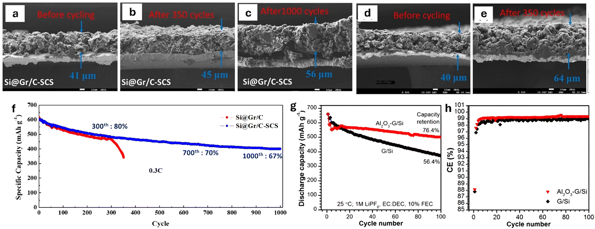 | ||
| Fig. 20 (a)–(c) Cross-sectional SEM images of silicon-graphite composite having A-SEI protective layer made of sulfonated chitosan (SCS) Si@Gr/C-SCS, and (d) and (e) silicon on graphite without A-SEI Si@Gr/C electrodes before and after cycling. (f) Cycling performance of the electrodes at 0.3C. Reproduced with permission from ref. 324. Copyright 2022, American Chemical Society. Cycling stability (g) and CE (h) of graphite-silicon (G/Si) and Al2O3 coating on G/S composite anode. Reproduced with permission from ref. 325. Copyright 2021, IOP Publishing Ltd. | ||
Zhu et al.325 used a low-cost and scalable sol–gel method to deposit Al2O3 coating as an A-SEI layer on silicon-graphite composite anodes. The Al2O3 coating transformed into a Li+ conductive Li–Al–O layer during lithiation, enhancing ionic conductivity while physically shielding the electrode from electrolyte decomposition. The coated composite anode exhibited significantly improved cycling performance and capacity retention, maintaining 76.4% capacity after 100 cycles at room temperature, compared to 56.4% for uncoated anode material (Fig. 20g and h). Additionally, at 55 °C, the Al2O3 coated anodes offered a capacity retention of 66.8% over 80 cycles, while the uncoated anodes retained only 27.6%.
Acknowledging these limitations, researchers have turned their focus toward oxide anodes as viable alternatives. Oxide anodes have emerged as a promising class of materials owing to their higher theoretical capacities and enhanced thermal stability from a reduced tendency for Li plating. These materials encompass a broad range of materials that can be categorized into two main types based on their Li storage mechanisms: conversion and intercalation type anodes. Fig. 21a shows a comparison of these two mechanisms. Conversion-type anodes, such as silicon oxides (SiOx), tin oxides (SnO2), and certain transition metal oxides, such as iron oxide (Fe2O3, Fe3O4), cobalt oxide (Co3O4), manganese oxide (MnO2), and nickel oxide (NiO), are known for their high theoretical capacities.328 Intercalation-type anodes, including lithium titanate (Li4Ti5O12), titanium dioxide (TiO2), and lithium vanadate (LVO), offer excellent reversibility.329,330 These materials operate at a higher potential (>1.55 V versus Li/Li+) and maintain zero-strain during cycling enhances their durability, making them particularly suitable for applications requiring high power and energy densities.
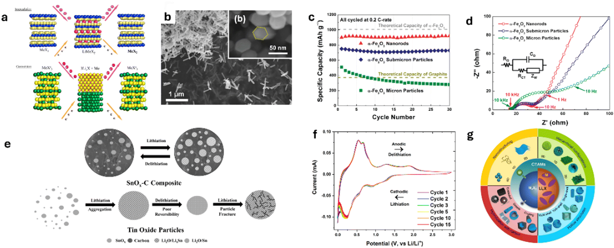 | ||
| Fig. 21 (a) Comparison of an intercalation and conversion mechanisms for the lithiation/delithiation of electrode materials. Reproduced with permission from ref. 331. Copyright 2007, Elsevier B.V. Illustration of conversion-type electrode lithiation behavior. (b) SEM images of α-Fe2O3 nanorods at a low magnification and (b) end-view at a high magnification. The yellow dashed line in panel b outlines the hexagonal structure of a single nanorod, (c) reversible capacities of α-Fe2O3 electrodes made with nanorods, submicrometer particles, and micrometer-sized particles. All electrodes cycled at 0.2C rate (201 mA g−1), and (d) electrochemical impedance spectroscopy of electrodes with α-Fe2O3 nanorods, submicrometer particles α-Fe2O3, and micrometer-sized particles α-Fe2O3. All measured after 100 cycles at 0.5C rate. Reproduced with permission from ref. 332. Copyright 2011, American Chemical Society. (e) Comparison of SnOx–C lithiation/delithiation versus unsupported tin oxide particle lithiation/delithiation and (f) long-term cyclic voltammograms of SnOx–C. Reproduced with permission from ref. 333. Copyright 2019, American Chemical Society. (g) Schematic Illustration of the nanoengineering strategies for high-performance conversion type anode materials for next-generation LIBs. Reproduced with permission from ref. 25. Copyright 2018, Elsevier Inc. | ||
A key advantage of oxide anodes over graphite is their reduced risk of dendrite formation, which leads to improved reversibility. Hou et al.334 demonstrated this by synthesizing a two-dimensional lamellar lithium titanate (Li4Ti5O12, LTO) anode material, which effectively suppressed Li dendrite formation. With a high Li+ diffusion coefficient and minimal volume changes, LTO enhances both safety and performance. Synthesized from a titanium-based MXene precursor, the lamellar structure improved Li+ transport and charge transfer. Electrochemical tests showed that LTO achieved 173 mA h g−1 after 100 cycles at 0.1C and retained 82% of its capacity after 1000 cycles at 2C, positioning it as a strong candidate for alternative anode material suitable in high-performance batteries. Liu et al.335 synthesized self-supported Li4Ti5O12-C (LTO-C) nanotube arrays directly on stainless steel foil using a scalable template-based method. These arrays, designed for use as anode materials in flexible LIBs, demonstrated exceptional performance with reversible capacities of 135 mA h g−1, 105 mA h g−1, and 80 mA h g−1 at charge/discharge rates of 30C, 60C, and 100C, respectively. The arrays also exhibited excellent cycling stability, retaining 93% of their capacity after 500 cycles at 10C, with a capacity retention of 144 mA h g−1. The carbon coating on the nanotubes significantly enhanced the electronic conductivity, contributing to a high-rate capability and long-term stability.
Conversion-type oxides, such as Fe2O3 and Fe3O4, have proven to be promising high-capacity anode materials due to their affordability, high capacity, and nontoxic nature. Lin et al.332 found that α-Fe2O3 nanorods as an anode material delivered high reversible capacities of 908 mA h g−1 at a 0.2C rate and 837 mA h g−1 at a 0.5C rate. The α-Fe2O3 nanorods averaged ∼40 nm in diameter and ∼400 nm in length, providing a short path for Li+ diffusion, reduced charge transfer resistance, and effective accommodation of the strain generated from the volume expansion during the lithiation/delithiation process (Fig. 21b–d). Chen et al.336 designed a sea urchin-like Fe3O4@C@NS-rGO composite with nitrogen and sulfur co-doped graphene coating to improve the conductivity and provide fast ion-diffusion pathways. The composite exhibited a high reversible capacity of 532.5 mA h g−1 after 100 cycles at 100 mA g−1 with an energy density of 232.1 W h kg−1 when paired with a LiCoO2 cathode. Other oxide anodes, such as SnO2, offer high capacity with stable cycling. Weeks et al.333 developed a tin oxide–carbon (SnOx–C) composite through the pyrolysis of a tin-citrate precursor. The resulting composite contained tin oxide nanocrystals surrounded by a flexible porous carbon framework. This structure enhanced reversibility during Li2O formation (Fig. 21f), reduced particle aggregation, suppressed volume expansion, and improved cycling stability to deliver a high initial capacity of 542 mA h g−1 and retained 80.6% of this capacity after 400 cycles at 1C.
Oxide anodes represent a significant advancement in LIB technology, offering enhanced safety, higher performance, and the potential for innovation. Their high theoretical capacities and improved thermal stabilities address the key limitations of traditional graphite anodes. Intercalation-type oxides provide excellent cycling stability and are suitable for high-rate applications due to their minimal volume change and higher operating potential. Conversion-type oxides offer the advantage of higher capacities to meet the demand for increased energy density. Continued research and development of these oxide anode materials are crucial for advancing LIBs technology to meet future energy storage needs (Fig. 21g).
c. Electrolyte
Given the growing demand for safer, higher-energy-density batteries, extensive research has been conducted to develop newer electrolyte systems that enhance safety while maintaining or improving performance. This section discusses additives, solid electrolytes and aqueous electrolyte as approaches to improving electrolyte safety.Currently, additives are classified based on their specific roles, such as SEI film formation and flame retardancy. Film-forming additives are crucial for creating protective surface films on the electrodes. So far, reductive compounds comprising fluorine donating functional groups have been the most explored as SEI-forming additives, particularly for high-specific capacity anodes such as Li metal and Si. It is worth noting that fluorinated solvents, including ethers, attract considerable attention as electrolyte additions, owing to their wider electrochemical stability window, low flammability, and inherent ability to form effective surface films on electrodes and current collectors. Among these, Fluoroethylene carbonate (FEC) is the most commonly used. Schroder et al.338 showed that FEC, when added to an EC/DEC electrolyte, significantly enhances the formation of a stable, LiF-rich SEI layer on Si anodes (Fig. 22a–f). They demonstrated that adding FEC resulted in a thicker SEI (35.1 nm) compared to the thinner SEI (23.1 nm) formed in the absence of FEC. The thicker, inorganic species-rich SEI effectively stabilized the anode surface, minimizing capacity loss during repeated cycling. The Si-anodes cycled in the FEC-containing electrolyte maintained a discharge capacity >3000 mA h g−1 after 100 cycles compared to 1252 mA h g−1 in the FEC absent electrolyte (Fig. 22g). From a safety perspective, this shows the FEC-containing electrolyte better curtails the degradation mechanisms of Si-anodes that result in catastrophic cell failures.
 | ||
| Fig. 22 Relative composition of the 10 nm SEI layer formed on an amorphous Si anode after: (a) first lithiation cycle in EC/DEC, (b) first lithiation cycle in EC/DEC/FEC, (c) first delithiation cycle in EC/DEC, (d) first delithiation cycle in EC/DEC/FEC, (e) 100 cycles in EC/DEC, and (f) 100 cycles in EC/DEC/FEC. Reproduced with permission from ref. 338. Copyright 2015 American Chemical Society. (g) 100 cycle performance of amorphous Si‖Li cell. Reproduced with permission from ref. 338. Copyright 2015 American Chemical Society. (h) Rate capability performance of NCM811‖Li half cells cycled in baseline (1 M LiPF6 in EC:DEC (50:50 v/v)), and baseline line electrolytes with 0.5 and 2 wt% VC, respectively. Reproduced under the terms of the Creative Commons CC-BY 4.0 license.339 Copyright 2024, The Authors. HAADF-STEM images of NCM811 after 100 cycles in (i) baseline electrolyte, and (j) Baseline + 2 wt% VC. (k) and (l) VC oxidation and polymerization pathways that allow the formation of stable CEI. Reproduced under the terms of the Creative Commons CC-BY 4.0 license.339 Copyright 2024 The Authors. | ||
FEC has also demonstrated its effectiveness as additive for high voltage operations.275 Zou et al.340 investigated the impact of FEC in a fluorinated ester-based electrolyte, designed to enhance cycling stability and power capability under extreme temperature conditions, fast charging, and high voltage. Their study revealed that FEC improved the electrolyte stability, oxidation resistance, and Li+ solvation dynamics, thereby enhancing the performance of NCM 811‖Gr cells at >4.3 V. The addition of FEC into the MDFA/PFPN/FEC electrolyte resulted in significantly improved initial CE (87.0%) and long-term cycling stability, with an 85.2% capacity retention after 200 cycles and 80.3% after 500 cycles.
In contrast, electrolytes lacking FEC exhibited rapid degradation, with significantly lower capacity retention. Hwang et al.341 showed that while FEC facilitates the in situ formation of a mechanically stable, electrically conductive, and elastic SEI layer, when combined with other additives, such as LiDFOB, and an ex situ LiNO3 anode treatment, which promotes Li2O formation in the SEI, better performance is attainable. Their study paired an Al-doped FCG Li[Ni0.75Co0.10Mn0.15]O2 cathode with the modified electrolyte/anode and reported an unprecedented high areal capacity of 4.1 mA h cm−2 and 80% capacity retention after 300 cycles at a current density of 3.6 mA cm−2. Moreover, pouch-type cells assembled using the modification approach retained 90% of their initial capacity over 500 cycles at a high current density of 1.8 mA cm−2, highlighting the practicality of this approach.
Vinylene carbonate (VC) is another additive that enhances the stability of the cathode electrolyte interface (CEI). VC undergoes oxidation at the cathode electrode at potentials lower than other carbonate solvents, resulting in the formation of insoluble products that contribute to the stability of the CEI, particularly at high voltages, by forming a polymeric protective layer that suppresses electrolyte decomposition at elevated temperatures.339 Dai et al. proposed that a uniform and cohesive CEI could protect the cathode by preventing transition metal mixing, dissolution, and surface construction at voltages up to 4.8 V.339 They suggested that VC oxidizes and initiates a polymerization process that forms a cohesive polymeric layer on the cathode (Fig. 22k). The protective polymeric layer inhibits the detrimental rock-salt-like phase that forms on NCM cathode surfaces along with a dense, uniform CEI that suppresses electrolyte decomposition, reducing the likelihood of suitable environments for thermal runaway events (Fig. 22h–j).
Flame retardant additives, often containing organic halogens, phosphorus, and phosphazene compounds, help mitigate the risk of thermal runaway.342 Among these, organic phosphorus compounds, such as trimethyl phosphate (TMP), triethyl phosphate (TEP), triphenyl phosphate (TPP), and dimethyl methyl phosphonate (DMMP) are the most commonly used due to their high efficiency, low toxicity, and low cost.
Typically, when the temperature within a LIB cell increases, these additives decompose, forming free radicals that replace hydrogen and hydroxy free radicals formed from electrolyte decomposition/combustion, leading to the termination of the combustion reaction.343 Dong et al.344 demonstrated a fire-retardant electrolyte consisting of 2.8 M LiTFSI in TEP with 10% FEC. The electrolyte composition demonstrated good thermal stability, with peak heat release rates (PHRR) elevated to 290 °C and negligible volatility below 150 °C, compared to conventional carbonate electrolytes with PHRR around 190 °C (Fig. 23a). The electrolyte was considerably nonflammable (Fig. 23b–d) and formed a stable LiF-rich SEI, leading to the high performance of dendrite-free Li‖LFP cells that retained 90% of their capacity over 2000 cycles at 1C. Its effectiveness was shown in high-voltage cathodes (NCM811), with a 95.7% capacity retention after 100 cycles.
 | ||
| Fig. 23 (a) Heat release profiles of TEP-based electrolytes (1 M LiTFSI in TEP, 2.8 M LiTFSI in TEP, and 2.8 M LiTFSI in TEP + 10 vol% FEC) obtained by microscale combustion calorimeter. Reproduced with permission from ref. 344. Copyright 2019, American Chemical Society. Photographs of ignition tests of glass fiber strips saturated with (b) 2.8 M LiTFSI electrolyte, (c) 2.8 M LiTFSI + 10 vol% FEC electrolyte, and (d) 1 M LiPF6 in EC:DMC (1:1, v/v). Reproduced with permission from ref. 344. Copyright 2019, American Chemical Society. (e) Structures of common flame retardant additives. Reproduced with permission from ref. 345. Copyright 2024, The Authors. (f) Rate performance of LFP‖Li cells cycled in 1 M LiFSI in DOL:PFPN (9:1, v/v) (LDP), 1 M LiFSI in DOL (LD) and 1 M LiPF6 in DMC:EC (7:3, v/v) (carbonate electrolyte). Reproduced with permission from ref. 346. Copyright 2024, The Royal Society of Chemistry. (g) Long-term cycling performance of LFP‖Gr cells cycled in LDP, DL, and carbonate electrolytes at 1C. Reproduced with permission from ref. 346. Copyright 2024, The Royal Society of Chemistry. | ||
Although effective, these phosphate-based additives suffer from poor reduction stability, especially when in contact with the graphite anode. To balance the flame-retarding effect and electrochemical performance of LIB electrolytes, cyclophosphazenes are an emerging category of flame-retardant additives. Cyclophosphazenes have ring structures consisting of alternating nitrogen and phosphorus atoms (Fig. 23e).347 The phosphorus molecules act as radical scavengers and promote char formation to enhance thermal insulation.347 The nitrogen molecules release non-combustible gases, such as NH3 and N2, further suppressing combustion. Liu et al.345 showed that adding 3 wt% ethoxy (pentafluoro) cyclotriphosphazene (PFPN) to a base electrolyte of 1 M LiPF6 in EC (1:1) significantly improved the electrolyte's flame retardancy, reducing the self-extinguishing time to 10 s g−1. The PFPN electrolyte also showed better compatibility with graphite cells, resulting in a 97.25% capacity retention after 100 cycles. Under fast charge conditions, the addition of PFPN to a 1 M LiFSI-based electrolyte in 1,3-dioxolane significantly improved both ionic conductivity and the formation of a stable, highly conductive SEI to enable superior fast-charging performance.346 PFPN not only enhanced the non-flammability of the electrolyte but also mitigated the corrosion of Al foil triggered by the LiFSI salt. Under extremely fast charge conditions, Li‖Gr cells delivered high reversible capacities of 314.2 mA h g−1 at 20C and 164.4 mA h g−1 at 50C (Fig. 23f). Additionally, LFP‖Gr pouch cells with an N/P ratio of 1.4 delivered an initial capacity of 127.9 mA h g−1 and maintained 127.5 mA h g−1 after 500 cycles (Fig. 23g).
Generally, two classes of materials are used as solid electrolytes in LIBs—inorganic ceramics and organic polymers,287 with hybrid ceramic–polymer-type solid electrolytes emerging recently.349 Inorganic ceramics are recognized for their solid-state ionic conductivity translating into high ionic conductivities exceeding the order of 10−2 S cm−1,350 particularly at elevated temperatures, and their mechanical stability. Some widely studied ceramic materials include halides, sulfides, garnets, and perovskites, such as Li3N, La0.5Li0.5TiO3, La3.25Ge0.25P0.75S4, Li7La3Zr2O12, Li10GeP2S12, Li10SnP2S12.350 Owing to the robust mechanical properties (high Young's modulus) of solid-state electrolytes, internal short-circuiting resulting from dendritic growth is suppressed,349 allowing better pairing of these electrolytes with Li metal anodes for higher energy densities. However, these materials are susceptible to oxidative instability and electronic percolation because of their high electronic conductivity, especially at high current densities, which can still lead to dendrite formation.351 Hence, modifying the electrolyte structure to withstand dendrite formation and suppress electronic conductivity while maintaining high ionic conductivity is crucial to ensure the full adoption of solid electrolytes (Fig. 24a).
 | ||
| Fig. 24 (a) Key issues new GPE approaches should mitigate. Reproduced with permission from ref. 352. Copyright 2023, The Authors. Photographs of ignition tests of glass fiber strips saturated with (b) Li+ and electronic conductivities of PMMA absent LiBH4 electrolyte (HT150-0PMMA) and 5% PMMA present LiBH4 electrolyte (HT150-5PMMA). Reproduced with permission from ref. 353. Copyright 2023, The Royal Society of Chemistry. (c) Schematic of the through-plane Li/aLLZO/LLZO/aLLZO/Li configuration employed. Reproduced with permission from ref. 354. Copyright 2021, The Authors. (d) Optical images of the LLZO pellet surface on the uncoated and aLLZO-coated side at the beginning of the plating-stripping process and after reaching a current density of 1.6 mA cm−2. Magnified image shows a Li filament short-circuiting the Li contacts in the uncoated side of the pellet. Reproduced with permission from ref. 354. Copyright 2021, The Authors. (e) Nyquist plot of the impedance response of the uncoated and aLLZO-coated LLZO pellets. Reproduced with permission from ref. 354. Copyright 2021, The Authors. (f) Schematic of Li+ diffusion through polar groups and segment movement of polymer chains in composite polymer electrolytes. Reproduced with permission from ref. 352. Copyright 2023, The Authors. | ||
To address this, Wei et al.353 explored an in situ melting reaction between lithium borohydride (LiBH4) and polymethyl methacrylate (PMMA). They observed that forming a covalently bonded coordination layer on the surface of the solid electrolyte particles via the in situ melting reaction blocks electronic percolation pathways by “locking” excess electrons in place (Fig. 24b), extends the oxidative stability of the electrolyte to suppress dendrite growth.
The coordination layer acted as a binder that strengthened the mechanical properties of the solid electrolyte, enabling it to withstand the stress and strain during Li plating/stripping. Additionally, the in situ modification extended the voltage window of the electrolyte to 10 V, offering unprecedented cycling stability for high-voltage applications. Sastre et al.354 proposed using amorphous Li–La–Zr–O (aLLZO) as a solution to Li dendrite formation in solid-state batteries (Fig. 24c). Unlike the crystalline version, the amorphous phase eliminates grain boundaries, which are common pathways for dendrites. The ultrathin 10 nm aLLZO films effectively blocked dendrite growth, allowing the battery to operate at current densities of up to 3.2 mA cm−2 with reduced impedance (Fig. 24d and e).
Organic polymers, particularly poly(ethylene oxide) (PEO), are another category of favorable materials for solid electrolytes because of their flexibility, lower cost, and easier processability compared to inorganic ceramics. Unlike gel polymer electrolytes with solvents confined in a polymer matrix, in solvent-free solid polymer electrolytes, Li salts are solvated by polymer chains. Compared with traditional liquid electrolytes, solid polymer electrolytes not only alleviate the danger of flammability and detrimental side reactions of the electrolyte with electrodes but also retain excellent adhesion and film-forming properties of polymers. However, while organic polymer electrolytes, such as the PEO-based electrolytes, exhibit good compatibility with Li salts and can stabilize the Li metal interface, their low ionic conductivity at room temperature remains a challenge, often requiring higher operating temperatures.
To overcome these limitations, hybrid solid electrolytes, which combine ceramic and polymer materials, have emerged as a promising solution to balance the benefits of both systems. Ceramic-polymer composite electrolytes offer high ionic conductivity along with the flexibility and processability of polymers. They are formed by adding ceramic fillers into polymeric solid electrolytes.352 Moreover, Li+ diffusion in this class of electrolyte is due to the polar groups and segment movement of polymer chains (Fig. 24f). Ceramic fillers like Li7La3Zr2O12 and Al2O3 act not only as ion conductors but also as structural reinforcements that prevent polymer crystallization, a major factor limiting the ionic mobility of pure polymer electrolytes.352 These fillers also create continuous ion-conducting pathways while increasing the electrolyte's shear modulus, effectively suppressing Li dendrite growth.293 The fillers' ability to interact with Li+ and prevent undesirable reactions with the anode or cathode extends the electrochemical stability window, making these hybrid electrolytes compatible with high-voltage layered oxide cathodes. Additionally, the ceramic particles improve the thermal stability of the electrolyte to reduce the risk of thermal runaway, especially under high-temperature operating conditions.352 By enhancing both the mechanical and electrochemical properties, hybrid polymer–ceramic electrolytes address the inherent weaknesses of liquid and polymer-only systems, thus significantly boosting the overall safety and performance of LIBs.
Adjusting the electrolyte's alkalinity is a common approach to widening the ESW. While this suppresses hydrogen evolution, it compromises anodic stability against oxygen evolution, resulting in high self-discharge rates.356,357 To address this limitation and widen the ESW of aqueous electrolytes whilst maintaining the safety aspects of aqueous electrolytes, the “water-in-salt” electrolyte (WiSE) concept has been developed. WiSE refers to aqueous electrolytes where the concentration of salt in water exceeds 5 M. In these systems, the salt molecules outnumber those of the solvent by both weight and volume,357 resulting in super-concentrated aqueous electrolytes. The enlargement of ESW offered by WiSE has been ascribed to the modification of the Li+ solvation sheaths (Fig. 25a), allowing a preferential decomposition of salt anions that form stable SEIs on the anode interface. Unlike non-aqueous electrolyte systems where SEI layers form and protect the electrodes, traditional aqueous electrolyte systems lack decomposition products capable of forming dense, stable interphases on the electrodes. This makes the WiSE approach promising, especially from a safety perspective.
 | ||
| Fig. 25 Performance of WiSE Reproduced with permission from ref. 357. Copyright 2015, American Association for Advancement of Science: (a) illustration of the evolution of the Li+ primary solvation sheath in diluted vs. water-in-salt solutions, (b) illustration of expanded electrochemical stability window for water-in-salt electrolytes paired with LiMn2O4 cathode and Mo6S8 anode, (b) TEM images of pristine Mo6S8 (c) and cycled Mo6S8 (d) in WiSE electrolyte. Performance of WIBS electrolytes. Reproduced with permission from ref. 358. Copyright 2016, Wiley-VCH: (e) cycling stability of LiMn2O4‖c-TiO2/TiO2 anodes in 12 M LiTFSI in water (WIS) and 21 M LITFSI + 7 M LiOTf (WIBS) electrolytes, (f) TEM images of C-TiO2 recovered after 143 cycles in WIBS at 1C, (g) and (h) XPS of C-TiO2 anode before and after 10 cycles at 0.5C, respectively in WIBS electrolyte. | ||
The most frequently studied WiSE systems are based on one Li salt, typically bis(trifluoromethane sulfonyl)imide (LiTFSI) or TFSI-derived salts because of their high solubility in water, ability to form fluorine-rich SEIs, and stability and lesser likelihood to undergo hydrolysis to form harmful byproducts, such as HF, compared to LiPF6. In 2015, Suo et al.357 demonstrated the suitability of WiSE using a LiTFSI-based electrolyte with molality >n. This allowed the formation of a SEI-beneficial anion-containing Li+ solvation sheath, causing the formation of a stable, passivating interphase on a Mo6S8 anode interface (Fig. 25c and d). The highly concentrated salt provided an ESW of ∼3 V (Fig. 25b), and the fully aqueous LiMn2O4‖Mo6S8 cell demonstrated high CEs for up to 1000 cycles at both low (0.15C) and high (4.5C) rates with a cell voltage of 2.3 V. This significant increase in the ESW allows more cathode and anode materials to be applied to aqueous LIBs, offering improved performance without sacrificing the inherent safety benefits of aqueous electrolytes.
Despite the promises of WiSe, limitations still exist. Drouget et al.359 demonstrated the instability of the SEI formed at the anode in this electrolyte system. They showed that the SEI in WiSE is not protective enough to prevent continuous parasitic reactions, such as water reduction and hydrogen evolution. For instance, when a Mo6S8‖LFP system was cycled with WiSE, significant gas evolution and capacity loss were observed. This was attributed to the SEI's inability to fully block hydrogen evolution, limiting the long-term cycling and thermal stability of WiSE-based systems. Moreover, the high concentration of LiTFSI used in WiSE is close to the saturation point of the salt at room temperature, indicating that further salt concentration cannot improve SEI.
To address the underlying issues of WiSE, super concentrated electrolytes using either two Li-based salts or one Li-based and one non-Li-based salt, called Water-in-Bisalt (WiBS), are also gaining momentum in aqueous electrolytes research. Greater salt concentrations are possible in WiBS systems due to the solubility of Li-based salts being increased by asymmetric ions. Since a hydrated salt, considered a saturated electrolyte, can dissolve another un-hydrated salt with similar chemical properties, it is possible to form mixed salt systems with higher cation/water ratios. Based on this, Suo et al.358 utilized a 21 M LiTFSI-based WiSE to dissolve lithium trifluoromethane sulfonate (LiOTf), resulting in a WiBS consisting of 21 M LiTFSI and 7 M LiOTf that offered better electrochemical performance (Fig. 25e) and formed a more efficient SEI (Fig. 25f–h). Additionally, bisalt electrolytes further reduce the electrochemical activity of water, reducing its likelihood for gas evolution, while depressing the liquidus temperature of the electrolyte.358
While WiSE and WiBS approaches demonstrate significant promises for enhancing the safety of aqueous LIBS, further research that focuses on the SEI stability in aqueous electrolyte systems is paramount to harness the full safety benefits of these electrolyte systems.
d. Cell level thermal runaway mitigation strategies
There are two main categories of thermal runaway mitigation strategies reported in the literature, namely the prevention in a cell and suppression of propagation across multiple cells. Kong et al.360 suggest various methods, like thermally responsive materials and the implementation of real-time monitoring systems. A study by Lai et al.361 investigated the effect of introducing a poison agent (Al2(SO4)3·16H2O) in high-energy batteries. They found that the maximum thermal runaway temperature can be reduced by more than 300 °C due to a new reaction sequence regulation. Two poisoning mechanisms were identified that revealed how the poison agent worked. The hydrate could react with LiPF6 and EC to hinder further exothermic reactions that relate to EC and the hydrate could poison the lithiated graphite and prevent the redox reaction between the cathode and the anode. It was noted that due to the significant reduction in the maximum temperature by the self-poisoning design of the system, more work needed to be conducted to test the feasibility of the toxic agent for practical applications.Friesen et al.362 investigated the safety behavior after thermal and mechanical abuse of 18650 Li-ion cells with Al2O3 coating on the anode surface and their aging at low temperatures. Post-mortem analysis showed a thick, irreversibly deposited Li metal layer beneath a mostly intact Al2O3 coating on the negative electrode. Safety tests in an open system confirmed that the coating remained effective despite Li deposition, ensuring a safe response for both fresh and aged cells. Under quasi-adiabatic conditions, aged cells exhibited increased reactivity, but both fresh and aged cells showed similar responses to thermal abuse (Fig. 26).
 | ||
| Fig. 26 Thermal abuse ARC experiments under quasi-adiabatic conditions. Reproduced with permission from ref. 362. Copyright 2017, Elsevier B.V. | ||
Naguib et al.363 developed a battery system with breakable electrodes for mitigating abuse by electrically isolating the internally shorted part of the battery from the rest of the cell before the separator is punctured. It was found that thermal runaway could be prevented by limiting the current passing through the shorted area. Likewise, FEM simulations were performed to identify the level of separation needed. The breakable electrodes were realized by introducing a certain slit pattern using a modified clicker die without affecting the conventional roll-to-roll production for battery electrodes. Batteries with slitted electrodes exhibited capacities and voltage profiles similar to those of standard batteries. When mechanically abused by heavy deformation, the modified battery did not short-circuit, while the standard one shorted and became nonfunctional. The modified battery was found to retain 93% of its capacity after the mechanical abuse test and was electrochemically viable.
Ji et al.364 developed a thermal shutdown separator with a shutdown temperature of 90 °C by coating thermoplastic ethylene-vinyl acetate copolymer (EVA) microspheres onto a conventional polyolefin membrane film and tested for thermal protection. The experimental results demonstrated that owing to the melting of the EVA coating layer at a critical temperature, this separator could promptly cut off the Li+ transport between the electrodes and thus shut down the battery reactions to protect the cell. In addition, this type of separator had no negative impact on the normal battery performance, therefore providing an internal and self-protecting mechanism. Shi et al.365 investigated alkanes (octane, pentadecane, and icosane) as thermal-runaway retardants. In nail penetration tests on coin cells, 4 wt% pentadecane reduced the maximum temperature by 60%. Similarly, in the impact test on pouch cells, 5 wt% pentadecane reduced the maximum temperature by 90%. The high mitigation effectiveness of pentadecane is attributed to its high wettability of the separator and its immiscibility with electrolyte. By forming a physical barrier between the cathode and anode, pentadecane interrupted Li+ transport and increased the charge transfer resistance by nearly two orders of magnitude. The diffusion rate of pentadecane in the electrode layer stack was measured to be 580 μm s−1.
Wen et al.366 investigated the effects of oxygen levels and dilution gases on thermal runaway propagation. They used a combustion chamber for pressure and gas control and analyzed the internal changes like electrode structure degradation, droplet formation, and decomposition of electrolyte and binder using X-ray computed tomography. They found that reduced oxygen concentration leads to decreased mass loss, weakening the progression and decreasing the heat and gas production, which leads to less structural degradation. It was observed that oxygen concentration control and inert gas diffusion were effective strategies for battery fire safety and thermal management. Another mitigation strategy is the introduction of hollow gas microspheres plates as thermal barriers. Niu et al.367 found that increasing the hollow gas microspheres plates decreased the propagation rate. Thermal runaway can be triggered in adjacent cells within a 3 mm distance, so mini channel cooling has also been studied by Xu et al.368 This method can prevent propagation, but it is not effective in stopping runaway in a single cell. On the other hand, Hu et al.369 proposed the use of water mist, which could significantly reduce the maximum battery temperature and decrease the likelihood of thermal runaway. It also explores the use of phase change material and composites.
Xu et al.370 tested three different extinguishing agents, including CO2, HFC-227ea, and water mist on the fire and their extinguishing properties on NCM/graphite cells. The NCM/graphite cells produced black smoke and violent jet fire, necessitating effective suppression measures to prevent fire propagation and ignition of battery materials. Among the tested extinguishing agents, only water mist effectively suppressed the fires. The cooling effects of these agents vary, with water mist providing the most significant temperature reduction, followed by HFC-227ea, which is slightly more effective than CO2. Temperature measurements before agent depletion show that water mist reduces peak average temperatures by up to 133 °C, significantly more than the other agents. Zhang et al.371 established a coupled electrochemical-thermal simulation model of thermal runaway propagation to supplement experimental data and public datasets for model training and verification. Multi-mode and multi-task thermal propagation forecasting neural network was established for advanced multi-step prediction along with a temperature-based propagation grading warning strategy. The validation of the simulation model involved experiments on single battery cells and battery modules. Single-cell tests were conducted in an ARC to precisely measure temperature changes, while module tests were performed on a specialized platform simulating real-world conditions.
5. Operational considerations: temperature and mechanical factors
One critical environmental condition that LIBs need to adapt to is a wide range of temperatures. With the advent of a thermal management system at relatively moderate temperatures, it is often necessary to account for their storage and start-up under extreme operating conditions.372 Applications such as space, deep-sea exploration, and military use, require optimal performance across extremely broad temperature ranges.373–375 Operating LIBs at such temperatures will often lead to significant changes in the ion diffusion kinetics and Li+ migration within the SEI layer.373,376 To address these challenges, significant efforts have been made to explore the thermodynamics and kinetics of anodes, cathodes, electrolytes, and additives, with the aim of enhancing the performance.377,378 A summary of the key operational considerations is shown in Fig. 27a. | ||
| Fig. 27 (a) Schematic of key operational considerations for practical LIBS. (b) Conductivities of three Li salts in various electrolytes versus temperature. Data extracted from Jet Propulsion Laboratory reported studies and (c) electron energy levels and electrode potential correlated with the HOMO/LUMO levels of the electrolyte governing thermodynamic stability with increasing temperature, and insets showing the SEI and CEI formed on the anode and cathode particle surfaces. Reproduced with permission from ref. 379. Copyright 2020, Wiley-VCH. | ||
For the operation at subzero temperatures, electrochemical reactions are expected to become kinetically sluggish compared to standard temperatures, leading to a significant decrease in electrolyte conductivity and diffusion coefficients. Furthermore, a significant increase in viscosity at these temperatures can cause the electrolyte to freeze, potentially leading to open circuits.380 Therefore, it is desirable to find an electrolyte with high conductivity and a low freezing point to avoid ohmic polarization induced by the reduced diffusion coefficient. The Jet Propulsion Laboratory showed the ternary mixture of ethylene carbonate (EC), diethyl carbonate (DEC), and dimethyl carbonate (DMC) yielded approximately 1 mS cm−1, which is higher at −40 °C (Fig. 27b) compared to other combinations, facilitating Li intercalation–deintercalation processes.381 Aliphatic esters and ethers such as 1,2-dimethoxyethane (DME), have been included to design the new solvent mixtures to lower the viscosity and freezing points of electrolyte solutions.382,383 In addition to having high ionic conductivity, it is also crucial for the electrolyte solution to have the ability to form a stable SEI on the anode electrode. The ability to form a stable SEI for the electrolyte solution including ester mixture was found to be lowest for low molecular weight esters and this enhanced as the polymer chain length increased.384,385
In contrast, different challenges must be met when operating LIBs at high temperatures. Even though the enhancement in solid/liquid diffusivity can be seen, the thermodynamics and kinetics of both SEI and CEI layers are significantly modified at high temperatures near 40 °C.379,386,387 Shifting of the highest occupied molecular orbit (HOMO) and lowest unoccupied molecular orbit (LUMO) yields a narrower energy gap between them, rendering the SEI and CEI unstable at higher temperatures (Fig. 27c). Electrolytes with low volatility are desirable to minimize the loss of liquid electrolyte in solution. Vapor pressure is often used to assess the thermal stability and safety of electrolytes for the design of LIBs.388 Due to the instability of LiFP6 at high temperatures, various new salts, including a Li salt based on a chelated borate anion (LiBOB), were studied for the formation of stable SEI.389 These new types of salts demonstrated similar battery capacity with LiFP6, but with improved capacity retention at 60 °C. Another challenge with high-temperature operations will be understanding the complex interfaces at the anode and cathode, including how the lithiated anode and delithiated cathode interact directly with the electrolyte and its degraded products through the SEI/CEI layers.390–392
When installing LIBs in new locations within a military vehicle, it is essential to consider both the temperature conditions and the mounting method.393 To ensure reliable performance and extend battery life, batteries should be protected from extreme temperatures and securely mounted to minimize vibration. Mounting batteries outside the engine bay can help manage battery temperature more effectively. However, if the distance from the alternator or starter motor is increased, longer electrical cables will be required, leading to greater electrical losses and reduced system efficiency. Additionally, if LIBs are installed in the passenger or operator compartment, appropriate measures must be taken to safely vent potentially harmful gases.
Understanding the effects of mechanical shocks and vibrations on battery performance in extreme operational environments is another crucial aspect to consider for the LIB system. The battery pack structure can be compromised when exposed to vibration and shock conditions, and electrical connection within the pack can be unstable during vehicle movements.394,395 Hooper et al. explored the degradation of cell materials caused by vibrations, using 18650 oxide-based battery cells.396,397 The direct current resistance of the oxide-based cells increases drastically when subjected to a vibration cycle representative of a 10-year vehicle life. Somerville et al. also demonstrated that surface films on battery cells formed due to vibrations contribute towards increased cell degradation, capacity loss, and higher cell impedance.398 Overall, understanding the correlation between vibrations and degraded battery performance is essential for ensuring the safety and optimal performance of LIBs.
6. Battery use in military operational settings
The operational considerations discussed regarding vibrations, shocks, and operation of LIBs in widely varying temperature environments are particularly concerning for military, first responder, and space operations that routinely use these batteries for energy storage. Since military and first responder operations are often characterized by extreme environments, additional design considerations for LIBs must be applied. The physical design of the internal battery components is important from a reliability standpoint. Rough handling of the battery when installed or transported in vehicles designed for rough terrain has been shown to adversely impact battery performance through degradation of internal connections. Changes in internal battery connections resulting in either short circuiting or large resistances can lead to thermal runaway or large voltage drops respectively.399Military operations often occur in extreme environments; desert heat to arctic cold, with wide ranges in humidity, and LIBs are often used in communications and optical equipment inherent to these operations. First responders, particularly firefighters, often operate in high-temperature environments. For safe operation of battery-powered equipment, the batteries must be able to maintain operation in these environments.400 Additionally, the batteries must be stable and maintain functionality over long periods of non-use, such as prolonged shelf-life in long-term storage. Military organizations often procure equipment in large quantities and store it for future use. The storage facilities for equipment may not be climate controlled, and storing batteries for long periods of time at high ambient temperatures can lead to significant decreases in battery life. A study on the degradation of LIBs due to long-term storage (two months) in temperature-controlled laboratory conditions led to a 3% drop in useful capacity.399
When worn on the body of military personnel, LIBs may be damaged due to ballistic impacts. While it may be of secondary importance relative to the impacts on personnel, the damage sustained by the battery may increase the danger to military personnel through violent exothermic reactions that could result in severe burns. The significance of safety issues inherent in ballistic impacts to battery casings was highlighted in a study focused on evaluating the feasibility of using LIB as supplemental body armor.401 This study used standard 7.62 × 39 mm ammunition fired at battery packs in combination with body armor used by current military forces. In this experiment, battery packs were mounted either in front of the body armor, or behind, and the ballistic protection afforded by the battery pack and the resulting damage to the battery was examined. In all tests, the batteries were crushed and perforated, and in the tests with partially charged batteries, the temperature of the battery pack rose to over 100 °C within 2 minutes of impact.401 These results lead to increased risk of burns and toxic fume inhalation by personnel.
Non-ballistic damage to LIBs can still result in the same safety issues due to short circuiting because of crushing or penetration of the battery housing. Mechanical failures can often arise during military operations that include transportation over rough terrain, equipment or personnel drops from aircraft, and equipment handling operations by heavy equipment or large numbers of personnel. Often battery failure due to these operations is a result of puncture or deformation of the battery case. Puncture tests on batteries have shown that foreign objects penetrating the battery case often result in a short circuit within the battery, leading to undesired side reactions and thermal runaway.402
Battery performance requirements for technology applications used by first responders and emergency personnel are based on reliability, safety, and longevity. These same requirements are essential for military applications. Programs such as the System Assessment and Validation for Emergency Responders (SAVER) program were initiated by the U.S. Department of Homeland Security (DHS) for developing specifications and performance requirements for emergency responder equipment and procurement.403 For example, both single-use and rechargeable Li-ion batteries with a cycle life of 400 cycles are required for firefighting equipment such as the self-contained breathing apparatus (SCBA).404 Single-use AA batteries and C cell batteries had the best performance in SCBAs at elevated temperatures. At −20 °C (−4 °F), an SCBA with C-cell batteries showed the lowest performance, lasting about 1.5 hours in full alarm mode with electronic safety features active.405 Moreover, single-use CR123 Li batteries did not discharge in high-temperature conditions. Testing results concluded that non-rechargeable back-up Li batteries failed to discharge at 54 °C (129 °F).405 Li-based batteries are best for use for first responder and military applications at extremely low temperatures and not advised for fire conditions due to thermal runaway at 140 °C (284 °F).406
The total weight of battery systems and components is a primary concern for their design, as they are mostly used for unmanned aerial vehicle (UAV) power supplies. For UAVs, two key performance parameters are energy capacity and overall battery weight.407 High energy density and low weight are important to sustain long UAV mission times. In addition to UAVs, military applications, including electromagnetic launch systems, directed energy weapons, and other high-power equipment, require LIBs capable of sustaining ultrahigh-rate discharge profiles of 10C to 20C for prolonged periods.408,409 These demanding conditions also necessitate a long charge/discharge cycle life. For example, the LIBs used in the 2003 Mars Exploration Rover were capable of exceeding 1000 cycles while maintaining 80% of their original capacity.410 Looking ahead, future ground vehicles for military applications will likely follow the growth in electric vehicle development in the civilian sector, decreasing reliance on petroleum-based fuels.411
Achieving higher energy density, improved energy efficiency, extended cycle life, and longer calendar life in LIBs also requires careful handling, storage, and charging procedures to mitigate associated risks. According to safety guidance from United States Naval Sea Systems Command,412–414 the total stored Li battery energy aboard ships must not exceed 1000 watt-hours in a single location, and that location must be approved by the Damage Control Assistant or Fire Marshal. In the event of thermal runaway, gases vented from burning Li cells may contain hazardous substances, such as HF. To minimize structural damage during such events, deliberate measures need to be placed to mitigate the direct impingement of hot gases from cell vents onto critical structural components of military platforms.
Furthermore, the catastrophic failure of LIBs can result in the release of large volumes of gas. To address this, pressure vessels are generally engineered with intentional failure mechanisms, preventing structural rupture using Belleville washers on bulkhead fasteners, urethane springs, and pressure relief devices such as discs, ports, or flapper valves.412–415 The battery system must also be engineered to minimize the risk of short circuits caused by operator error or system malfunctions. Such mitigation can be achieved through the strategic use of electrical interruption devices and/or physical design layouts that protect both the user and the battery from injury or catastrophic failure. Electrical safety devices (ESDs), such as contactors, fuses, circuit breakers, need to be validated through testing under voltage and current conditions representative of both normal operation and potential failure scenarios.412–414
7. Conclusion
The interconnection between electrochemical reactions and mechanical stress has been shown to influence the performance and lifespan of LIB components. In particular, cathode degradation, which is driven by microcracking, phase transitions, and oxygen release, coupled with the intrinsic challenges of anode materials and electrolytes trigger a complex matrix of failure pathways that culminate in catastrophic thermal events. Advanced strategies to mitigate these risks have emerged as key enablers for next-generation LIBs. Structural modifications such as concentration-gradient designs and the development of nanorod cathode architectures have significantly improved Li+ transport and mechanical integrity, while surface coating techniques using fluoride and phosphate compounds have been effective in suppressing parasitic side reactions and stabilizing interfacial layers. On the anode side, composite architectures and A-SEI layers have demonstrated the potential to balance high energy density with enhanced mechanical stability. Moreover, electrolyte engineering has contributed to reducing flammability risks and extending the electrochemical stability window.Operational factors, including extreme temperature variations and mechanical stresses, further complicate LIB performance, especially in demanding applications such as military operations. The integration of novel materials and engineering approaches that account for thermal and mechanical influences is critical for ensuring long-term reliability and safety. While significant progress has been achieved in understanding and mitigating degradation mechanisms in LIBs, ongoing research is essential. Future research should focus on improving the interfacial behaviors between electrodes and electrolytes by considering multifunctional electrolyte additives/solvents to develop better SEI layers that can withstand mechanical and thermal stresses. There is also a need to explore new electrolyte formulations that minimize parasitic reactions and enhance thermal stability, particularly in aqueous systems where current SEI layers are inadequate. Research should also focus on innovative electrode architectures, particularly cathodes, as cathode design has a more substantial impact on internal resistance and battery safety than anodes. Given the unique challenges faced in military and first responder applications, future work should specifically address the performance of LIBs under military-specific conditions, prioritizing focus on operations under harsh temperatures, mechanical shocks, and vibrations. Investigating advanced thermal management strategies is also crucial. This would be to develop materials that can dissipate heat more effectively and prevent thermal runaway events. Additionally, while not extensively covered in this review article, future research should focus on improving the mechanical and thermal stability of LIB separators, given the highlighted cell and pack-level risks that internal short circuits and damage to separators pose. These efforts will not only enhance battery performance and safety but will also pave the way for the broader adoption of LIB technology in safety-critical applications.
Author contributions
The manuscript was written with contributions from all authors. All authors have approved the final version of the manuscript. Idris Adebanjo and Juliana Eko: original manuscript writing, editing, and formatting. Anita Gift Agbeyegbe: original manuscript writing and reviewing. Jang-Yeon Hwang and H. Hohyun Sun: idea conceptualization, supervision, and manuscript review. Simuck F. Yuk, Enoch A. Nagelli, Samuel V. Cowart, F. John Burpo, Jan L. Allen, and Dat T. Tran: original manuscript writing (military perspective). Nishma Bhattarai: original manuscript writing. Krishna Shah: supervision and manuscript review.Data availability
The review paper is based on an analysis of existing literature. No primary research results have been included, and no new data was generated. The references used in this paper are publicly available and can be accessed through online databases.Conflicts of interest
There are no conflicts to declare.Acknowledgements
This work was supported by the University of Alabama College of Engineering startup funding. The views expressed herein are those of the authors and do not reflect the position of the United States Military Academy, the Department of the Army, or the Department of Defense.References
- J. P. Pender, G. Jha, D. H. Youn, J. M. Ziegler, I. Andoni, E. J. Choi, A. Heller, B. S. Dunn, P. S. Weiss, R. M. Penner and C. B. Mullins, Electrode Degradation in Lithium-Ion Batteries, ACS Nano, 2020, 14, 1243–1295 CrossRef CAS.
- S. Chen, Z. Gao and T. Sun, Safety Challenges and Safety Measures of Li-ion Batteries, Energy Sci. Eng., 2021, 9, 1647–1672 CrossRef.
- D. Ren, X. Feng, L. Lu, M. Ouyang, S. Zheng, J. Li and X. He, An Electrochemical-Thermal Coupled Overcharge-to-Thermal-Runaway Model for Lithium-Ion Battery, J. Power Sources, 2017, 364, 328–340 CrossRef CAS.
- E. A. Kapp, D. S. Wroth and J. T. Chapin, Analysis of Thermal Runaway Incidents Involving Lithium Batteries in U.S. Commercial Aviation, Transp. Res. Rec., 2020, 2674, 584–592 CrossRef.
- Q. Wang, P. Ping, X. Zhao, G. Chu, J. Sun, C. Chen, Q. Wang, P. Ping, X. Zhao, G. Chu, J. Sun and C. Chen, Thermal Runaway Caused Fire and Explosion of Lithium-Ion Battery, J. Power Sources, 2012, 208, 210–224 CrossRef CAS.
- J. Lamb, C. J. Orendorff, L. A. M. Steele and S. W. Spangler, Failure Propagation in Multi-Cell Lithium-Ion Batteries, J. Power Sources, 2014, 283, 517–523 CrossRef.
- J. Mouawad, Report on Boeing 787 Dreamliner Battery Flaws Finds Lapses at Multiple Points, 2014, https://www.nytimes.com/2014/12/02/business/report-on-boeing-787-dreamliner-batteries-assigns-some-blame-for-flaws, (accessed September 2024).
- United States Consumer Product Safety Commission, Samsung Recalls Galaxy Note7 Smartphones Due to Serious Fire and Burn Hazards, 2017, https://www.cpsc.gov/Recalls/2017/Samsung-Expands-Recall-of-Galaxy-Note7-Smartphones-Based-on-Additional-Incidents-with-Replacement-Phones, (accessed September 2024).
- M. McKinnon, S. DeCrane and S. Kerber, Four Firefighters Injured in Lithium-Ion Battery Energy Storage System Explosion-Arizona, 2020 DOI:10.54206/102376/TEHS4612, (accessed September 2024).
- A. Blum and T. Bensen, Victorian Big Battery Fire: July 30, 2021: Report of Technical Findings, 2021, https://infrastructure.planninginspectorate.gov.uk/wp-content/ipc/uploads/projects/EN010106/EN010106-004097-DL2%20-%20Edmund%20Fordham%20EF20.pdf, (accessed September 2024).
- K. Liu, Y. Liu, D. Lin, A. Pei and Y. Cui, Materials for Lithium-Ion Battery Safety, Sci. Adv., 2018, 168, 110520 Search PubMed.
- H. H. Ryu, K. J. Park, C. S. Yoon and Y. K. Sun, Capacity fading of Ni-rich li[NixCoyMn1−x−y]O2 (0.6 ≤ x ≤ 0.95) Cathodes for High-Energy-Density Lithium-Ion Batteries: Bulk or Surface Degradation?, Chem. Mater., 2018, 30, 1155–1163 CrossRef CAS.
- J. Chen, H. Yang, T. Li, C. Liu, H. Tong, J. Chen, Z. Liu, L. Xia, Z. Chen, J. Duan and L. Li, The Effects of Reversibility of H2–H3 Phase Transition on Ni-Rich Layered Oxide Cathode for High-Energy Lithium-Ion Batteries, Front. Chem., 2019, 7, 500 CrossRef CAS.
- T. Li, X. Z. Yuan, L. Zhang, D. Song, K. Shi and C. Bock, Degradation Mechanisms and Mitigation Strategies of Nickel-Rich NMC-Based Lithium-Ion Batteries, Electrochem. Energy Rev., 2020, 3, 43–80 CrossRef.
- M. Jiang, D. L. Danilov, R. A. Eichel and P. H. L. Notten, A Review of Degradation Mechanisms and Recent Achievements for Ni-Rich Cathode-Based Li-Ion Batteries, Adv. Energy Mater., 2021, 11, 2103005 CrossRef CAS.
- K. J. Park, J. Y. Hwang, H. H. Ryu, F. Maglia, S. J. Kim, P. Lamp, C. S. Yoon and Y. K. Sun, Degradation Mechanism of Ni-Enriched NCA Cathode for Lithium Batteries: Are Microcracks Really Critical?, ACS Energy Lett., 2019, 4, 1394–1400 CrossRef CAS.
- H. H. Ryu, G. T. Park, C. S. Yoon and Y. K. Sun, Microstructural Degradation of Ni-Rich Li[NixCoyMn1−x−y]O2 Cathodes During Accelerated Calendar Aging, Small, 2018, 14, 1803179 CrossRef.
- L. Wu, K. W. Nam, X. Wang, Y. Zhou, J. C. Zheng, X. Q. Yang and Y. Zhu, Structural Origin of Overcharge-Induced Thermal Instability of Ni-Containing Layered-Cathodes for High-Energy-Density Lithium Batteries, Chem. Mater., 2011, 23, 3953–3960 CrossRef CAS.
- H. H. Sun, A. Dolocan, J. A. Weeks, R. Rodriguez, A. Heller and C. B. Mullins, In Situ Formation of a Multicomponent Inorganic-rich SEI layer Provides a Fast Charging and High Specific Energy Li-metal Battery, J. Mater. Chem. A, 2019, 7, 17782–17789 RSC.
- M. Jiang, D. L. Danilov, R. A. Eichel and P. H. L. Notten, A Review of Degradation Mechanisms and Recent Achievements for Ni-Rich Cathode-Based Li-Ion Batteries, Adv. Energy Mater., 2021, 11, 2103005 CrossRef CAS.
- Z. Zhang, S. Said, A. J. Lovett, R. Jervis, P. R. Shearing, D. J. L. Brett and T. S. Miller, The Influence of Cathode Degradation Products on the Anode Interface in Lithium-Ion Batteries, ACS Nano, 2024, 18, 9389–9402 Search PubMed.
- L. Huang, G. Xu, X. Du, J. Li, B. Xie, H. Liu, P. Han, S. Dong, G. Cui and L. Chen, Uncovering LiH Triggered Thermal Runaway Mechanism of a High-Energy LiNi0.5Co0.2Mn0.3O2/Graphite Pouch Cell, Adv. Sci., 2021, 8, 2100676 CrossRef CAS.
- S. J. Gross, M. T. Hsieh, D. R. Mumm, L. Valdevit and A. Mohraz, Alleviating Expansion-Induced Mechanical Degradation in Lithium-Ion Battery Silicon Anodes via Morphological Design, Extreme Mech. Lett., 2022, 54, 101746 CrossRef.
- M. T. McDowell, S. W. Lee, W. D. Nix and Y. Cui, 25th anniversary article: Understanding the Lithiation of Silicon and Other Alloying Anodes for Lithium-Ion Batteries, Adv. Mater., 2013, 25, 4966–4985 CrossRef CAS PubMed.
- Y. Lu, L. Yu and X. W. (David) Lou, Nanostructured Conversion-Type Anode Materials for Advanced Lithium-Ion Batteries, Chem, 2018, 4, 972–996 CAS.
- S. H. Kim, K. Dong, H. Zhao, A. A. El-Zoka, X. Zhou, E. V. Woods, F. Giuliani, I. Manke, D. Raabe and B. Gault, Understanding the Degradation of a Model Si Anode in a Li-Ion Battery at the Atomic Scale, J. Phys. Chem. Lett., 2022, 13, 8416–8421 CrossRef CAS PubMed.
- Q. K. Zhang, X. Q. Zhang, H. Yuan and J. Q. Huang, Thermally Stable and Nonflammable Electrolytes for Lithium Metal Batteries: Progress and Perspectives, Small Sci., 2021, 1, 2100058 CrossRef CAS.
- J. Lamb, C. J. Orendorff, E. P. Roth and J. Langendorf, Studies on the Thermal Breakdown of Common Li-Ion Battery Electrolyte Components, J. Electrochem. Soc., 2015, 162, A2131–A2135 CrossRef CAS.
- Y. Liao, H. Zhang, Y. Peng, Y. Hu, J. Liang, Z. Gong, Y. Wei and Y. Yang, Electrolyte Degradation During Aging Process of Lithium-Ion Batteries: Mechanisms, Characterization, and Quantitative Analysis, Adv. Energy Mater., 2024, 14, 2304295 CrossRef CAS.
- Z. Zhu and J. Chen, Review—Advanced Carbon-Supported Organic Electrode Materials for Lithium (Sodium)-Ion Batteries, J. Electrochem. Soc., 2015, 162, A2393–A2405 CrossRef CAS.
- R. Febrian, N. L. W. Septiani, M. Iqbal and B. Yuliarto, Review—Recent Advances of Carbon-Based Nanocomposites as the Anode Materials for Lithium-Ion Batteries: Synthesis and Performance, J. Electrochem. Soc., 2021, 168, 110520 CrossRef CAS.
- F. Wang, O. Borodin, M. S. Ding, M. Gobet, J. Vatamanu, X. Fan, T. Gao, N. Edison, Y. Liang, W. Sun, S. Greenbaum, K. Xu and C. Wang, Hybrid Aqueous/Non-aqueous Electrolyte for Safe and High-Energy Li-Ion Batteries, Joule, 2018, 2, 927–937 CrossRef CAS.
- S. Khalid, N. Pianta, P. Mustarelli and R. Ruffo, Use of Water-In-Salt Concentrated Liquid Electrolytes in Electrochemical Energy Storage: State of the Art and Perspectives, Batteries, 2023, 9, 9010047 CrossRef.
- J. Yang, X. Liang, H. H. Ryu, C. S. Yoon and Y. K. Sun, Ni-rich Layered Cathodes for Lithium-Ion Batteries: From Challenges to the Future, Energy Storage Mater., 2023, 63, 102969 CrossRef.
- H. Zhang, Z. Zeng, S. Cheng and J. Xie, Recent Progress and Perspective on Lithium Metal Battery with Nickel-Rich Layered Oxide Cathode, eScience, 2024, 4, 100265 CrossRef.
- Q. Tao, L. Wang, C. Shi, J. Li, G. Chen, Z. Xue, J. Wang, S. Wang and H. Jin, Understanding the Ni-rich Layered Structure Materials for High-Energy Density Lithium-Ion Batteries, Mater. Chem. Front., 2021, 5, 2607–2622 RSC.
- Y. Chen, G. X. Wang, K. Konstantinov, H. K. Liu and S. X. Dou, Synthesis and Characterization of LiCoxMnyNi1−x−yO2 as a Cathode Material for Secondary Lithium Batteries, J. Power Sources, 2023, 119–121, 184–188 Search PubMed.
- Y. K. Sun, S. T. Myung, B. C. Park, J. Prakash, I. Belharouak and K. Amine, High-Energy Cathode Material for Long-Life and Safe Lithium Batteries, Nat. Mater., 2009, 8, 320–324 CrossRef CAS.
- S. T. Myung, F. Maglia, K. J. Park, C. S. Yoon, P. Lamp, S. J. Kim and Y. K. Sun, Nickel-Rich Layered Cathode Materials for Automotive Lithium-Ion Batteries: Achievements and Perspectives, ACS Energy Lett., 2017, 2, 196–223 CrossRef CAS.
- R. Lin, S. M. Bak, Y. Shin, R. Zhang, C. Wang, K. Kisslinger, M. Ge, X. Huang, Z. Shadike, A. Pattammattel, H. Yan, Y. Chu, J. Wu, W. Yang, M. S. Whittingham, H. L. Xin and X. Q. Yang, Hierarchical Nickel Valence Gradient Stabilizes High-Nickel Content Layered Cathode Materials, Nat. Commun., 2021, 12, 1–10 CrossRef PubMed.
- H. H. Sun, H. H. Ryu, U. H. Kim, J. A. Weeks, A. Heller, Y. K. Sun and C. B. Mullins, Beyond Doping and Coating: Prospective Strategies for Stable High-Capacity Layered Ni-Rich Cathodes, ACS Energy Lett., 2020, 5, 1136–1146 CrossRef CAS.
- Y. K. Sun, Z. Chen, H. J. Noh, D. J. Lee, H. G. Jung, Y. Ren, S. Wang, C. S. Yoon, S. T. Myung and K. Amine, Nanostructured High-Energy Cathode Materials for Advanced Lithium Batteries, Nat. Mater., 2012, 11, 942–947 CrossRef CAS.
- J. H. Ge, M. Y. Xie, Q. F. Zhao, S. Q. Zhang and H. Sun, Advances in Co-Free Layered Cathode Materials for Li-Ion Batteries, Int. J. Electrochem. Sci., 2023, 18, 100292 CrossRef.
- S. Aryal, J. L. Durham, A. L. Lipson, K. Z. Pupek and O. Kahvecioglu, Roles of Mn and Co in Ni-Rich Layered Oxide Cathodes Synthesized Utilizing a Taylor Vortex Reactor, Electrochim. Acta, 2021, 391, 138929 CrossRef CAS.
- E. Jo, J. H. Park, J. Park, J. Hwang, K. Y. Chung, K. W. Nam, S. M. Kim and W. Chang, Different Thermal Degradation Mechanisms: Role of Aluminum in Ni-rich Layered Cathode Materials, Nano Energy, 2020, 78, 105367 CrossRef CAS.
- Y. Su, Q. Zhang, L. Chen, L. Bao, Y. Lu, S. Chen and F. Wu, Stress Accumulation in Ni-Rich Layered Oxide Cathodes: Origin, Impact, and Resolution, J. Energy Chem., 2022, 65, 236–253 CrossRef CAS.
- S. Zhao, Z. Guo, K. Yan, S. Wan, F. He, B. Sun and G. Wang, Towards High-Energy-Density Lithium-Ion Batteries: Strategies for Developing High-Capacity Lithium-Rich Cathode Materials, Energy Storage Mater., 2021, 34, 716–734 CrossRef.
- S. Cao, C. Wu, X. Xie, H. Li, Z. Zang, Z. Li, G. Chen, X. Guo and X. Wang, Suppressing the Voltage Decay Based on a Distinct Stacking Sequence of Oxygen Atoms for Li-Rich Cathode Materials, ACS Appl. Mater. Interfaces, 2021, 13, 17639–17648 CrossRef CAS PubMed.
- X. Cao, H. Li, Y. Qiao, M. Jia, P. He, J. Cabana and H. Zhou, Achieving Stable Anionic Redox Chemistry in Li-Excess O2-type layered oxide cathode via chemical ion-exchange strategy, Energy Storage Mater., 2021, 38, 1–8 Search PubMed.
- W. He, W. Guo, H. Wu, L. Lin, Q. Liu, X. Han, Q. Xie, P. Liu, H. Zheng, L. Wang, X. Yu and D.-L. Peng, Challenges and Recent Advances in High Capacity Li-Rich Cathode Materials for High Energy Density Lithium-Ion Batteries, Adv. Mater., 2021, 33, 2005937 CrossRef CAS.
- H. Xie, J. Xiao, H. Chen, B. Zhang, K. N. Hui, S. Zhang, C. Liu, D. Luo and Z. Lin, Fundamental Understanding of Voltage Decay in Li-rich Mn-Based Layered Oxides Cathode Materials, AAPPS Bull., 2024, 34, 1–34 CrossRef.
- Y. Xie, Y. Jin and L. Xiang, Li-Rich Layered Oxides: Structure, Capacity and Voltage Fading Mechanisms and Solving Strategies, Particuology, 2022, 61, 1–10 CrossRef CAS.
- Z. Wang, H. Luo, H. Liu, F. Wu, C. Zhang, Z. Wang and P. Yu, Electrochemical Performance and Structural Stability of Layered Li–Ni–Co–Mn Oxide Cathode Materials in Different Voltage Ranges, Ceram. Int., 2021, 47, 8490–8497 Search PubMed.
- B. Li, Z. Zhuo, L. Zhang, A. Iadecola, X. Gao, J. Guo, W. Yang, A. V. Morozov, A. M. Abakumov and J. M. Tarascon, Decoupling the roles of Ni and Co in Anionic Redox Activity of Li-rich NMC Cathodes, Nat. Mater., 2023, 22, 1370–1379 Search PubMed.
- Q. Li, D. Ning, D. Wong, K. An, Y. Tang, D. Zhou, G. Schuck, Z. Chen, N. Zhang and X. Liu, Improving the Oxygen Redox Reversibility of Li-Rich Battery Cathode Materials via Coulombic Repulsive Interactions Strategy, Nat. Commun., 2022, 13, 1123 CrossRef CAS.
- Z. Li, S. Cao, J. Chen, L. Wu, M. Chen, H. Ding, R. Wang, W. Guo, Y. Bai, M. Liu and X. Wang, Modulating Surface Architecture and Electronic Conductivity of Li-rich Manganese-Based Cathode, Small, 2024, 20, 2400641 CrossRef CAS.
- H. He, H. Li, X. Bai, Z. Chang, Z. Gao, X. Zhang and Z. Ren, Comparative Study of High-Temperature Cycling and Thermal Stability of LLOs and NCMs under Medium-High Voltage, Energy Fuels, 2023, 37, 6854–6864 Search PubMed.
- X. Li, Q. Gu, B. Qiu, C. Yin, Z. Wei, W. Wen, Y. Zhang, Y. Zhou, H. Gao, H. Liang, Z. He, M. Zhang, Y. S. Meng and Z. Liu, Rational Design of Thermally Stable Polymorphic Layered Cathode Materials for Next Generation Lithium Rechargeable Batteries, Mater. Today, 2022, 61, 91–103 CrossRef CAS.
- H. Zheng, X. Han, W. Guo, L. Lin, Q. Xie, P. Liu, W. He, L. Wang and D. L. Peng, Recent Developments and Challenges of Li-Rich Mn-Based Cathode Materials for High-Energy Lithium-Ion Batteries, Mater. Today Energy, 2020, 18, 100518 Search PubMed.
- J. Liu, J. Wang, Y. Ni, K. Zhang, F. Cheng and J. Chen, Recent Breakthroughs and Perspectives of High-Energy Layered Oxide Cathode Materials for Lithium Ion Batteries, Mater. Today, 2021, 43, 132–165 Search PubMed.
- L. de Biasi, B. Schwarz, T. Brezesinski, P. Hartmann, J. Janek and H. Ehrenberg, Chemical, Structural, and Electronic Aspects of Formation and Degradation Behavior on Different Length Scales of Ni-Rich NCM and Li-Rich HE-NCM Cathode Materials in Li-Ion Batteries, Adv. Mater., 2019, 31, 1900985 CrossRef.
- X. Zhu, A. Huang, I. Martens, N. Vostrov, Y. Sun, M. I. Richard, T. U. Schülli and L. Wang, High-Voltage Spinel Cathode Materials: Navigating the Structural Evolution for Lithium-Ion Batteries, Adv. Mater., 2024, 36, 2403482 CrossRef CAS.
- W. D. Johnston and R. R. Heikes, A Study of the LixMn(1−x)O System, J. Am. Chem. Soc., 1956, 78, 3255–3260 CrossRef CAS.
- S. Liu, B. Wang, X. Zhang, S. Zhao, Z. Zhang and H. Yu, Reviving the Lithium-Manganese-Based Layered Oxide Cathodes for Lithium-Ion Batteries, Matter, 2021, 4, 1511–1527 CrossRef CAS.
- X. Zhu, A. Huang, I. Martens, N. Vostrov, Y. Sun, M. I. Richard, T. U. Schülli and L. Wang, High-Voltage Spinel Cathode Materials: Navigating the Structural Evolution for Lithium-Ion Batteries, Adv. Mater., 2024, 36, 2403482 CrossRef CAS.
- W. Wen, B. Kumarasamy, S. Mukerjee, M. Auinat and Y. Ein-Eli, Origin of 5 V Electrochemical Activity Observed in Non-Redox Reactive Divalent Cation Doped LiM0.5−xMn1.5+xO4 (0 < 0.5) Cathode Materials In Situ XRD and XANES Spectroscopy Studies, J. Electrochem. Soc., 2005, 152, A1902 CrossRef CAS.
- M. Armand, P. Axmann, D. Bresser, M. Copley, K. Edström, C. Ekberg, D. Guyomard, B. Lestriez, P. Novák, M. Petranikova, W. Porcher, S. Trabesinger, M. Wohlfahrt-Mehrens and H. Zhang, Lithium-Ion Batteries – Current State of the Art and Anticipated Developments, J. Power Sources, 2020, 479, 228708 CrossRef CAS.
- Y. Huang, Y. Dong, S. Li, J. Lee, C. Wang, Z. Zhu, W. Xue, Y. Li and J. Li, Lithium Manganese Spinel Cathodes for Lithium-Ion Batteries, Adv. Energy Mater., 2021, 11, 2000997 CrossRef CAS.
- Y. Deng, L. He, J. Ren, Q. Zheng, C. Xu and D. Lin, Reinforcing Cycling Stability and Rate Capability of LiNi0.5Mn1.5O4 Cathode by Dual-Modification of Coating and Doping of a Fast-Ion Conductor, Mater. Res. Bull., 2018, 100, 333–344 CrossRef CAS.
- S. Geller and J. L. Durand, Refinement of the Structure of LiMnPO4, Acta Crystallogr., 1960, 13, 325–331 CrossRef CAS.
- A. K. Padhi, K. S. Nanjundaswamy and J. B. Goodenough, Phospho-Olivines as Positive-Electrode Materials for Rechargeable Lithium Batteries, J. Electrochem. Soc., 1997, 144, 1188–1194 CrossRef CAS.
- J. Li and Z.-F. Ma, Past and Present of LiFePO4: From Fundamental Research to Industrial Applications, Chem, 2019, 5, 3–6 CAS.
- T. V. S. L. Satyavani, A. Srinivas Kumar and P. S. V. Subba Rao, Methods of Synthesis and Performance Improvement of Lithium Iron Phosphate for High Rate Li-Ion Batteries: A Review, Eng. Sci. Technol., Int. J., 2016, 19, 178–188 Search PubMed.
- S. W. Oh, S. T. Myung, S. M. Oh, K. H. Oh, K. Amine, B. Scrosati and Y. K. Sun, Double Carbon Coating of LiFePO4 as High Rate Electrode for Rechargeable Lithium Batteries, Adv. Mater., 2010, 22, 4842–4845 CrossRef CAS.
- S. W. Oh, S. T. Myung, H. J. Bang, C. S. Yoon, K. Amine and Y. K. Sun, Nanoporous Structured LiFePO4 with Spherical Microscale Particles having High Volumetric Capacity for Lithium Batteries, Electrochem. Solid-State Lett., 2009, 12, A181 CrossRef CAS.
- K. Y. Park, I. Park, H. Kim, G. Yoon, H. Gwon, Y. Cho, Y. S. Yun, J. J. Kim, S. Lee, D. Ahn, Y. Kim, H. Kim, I. Hwang, W. S. Yoon and K. Kang, Lithium-Excess Olivine Electrode for Lithium Rechargeable Batteries, Energy Environ. Sci., 2016, 9, 2902–2915 RSC.
- Q. Zhao, Y. Zhang, Y. Meng, Y. Wang, J. Ou, Y. Guo and D. Xiao, Phytic Acid Derived LiFePO4 Beyond Theoretical Capacity as High-Energy Density Cathode for Lithium Ion Battery, Nano Energy, 2017, 34, 408–420 CrossRef CAS.
- Z. Yang and S. Wang, High Cycling Performance Cathode Material: Interconnected LiFePO4/Carbon Nanoparticles Fabricated by Sol-Gel Method, J. Nanomater., 2014, 2014, 1–7 Search PubMed.
- M. Yang, Y. Ye, A. Yang, Z. Jiang, X. Wang, H. Yuan and M. Rong, Comparative Study on Aging and Thermal Runaway of Commercial LiFePO4/Graphite Battery Undergoing Slight Overcharge Cycling, J. Energy Storage, 2022, 50, 104691 CrossRef.
- Y. Zhang, S. Cheng, W. Mei, L. Jiang, Z. Jia, Z. Cheng, J. Sun and Q. Wang, Understanding of thermal runaway mechanism of LiFePO4 battery in-depth by three-level analysis, Appl. Energy, 2023, 336, 120695 CrossRef CAS.
- L. Song, Z. Huang, W. Mei, Z. Jia, Y. Yu, Q. Wang and K. Jin, Thermal Runaway Propagation Behavior and Energy Flow Distribution Analysis of 280 A h LiFePO4 Battery, Process Saf. Environ. Prot., 2023, 170, 1066–1078 CrossRef CAS.
- H. Chen, K. Yang, Y. Liu, M. Zhang, H. Liu, J. Liu, Z. Qu and Y. Lai, Experimental Investigation of Thermal Runaway Behavior and Hazards of a 1440 A h LiFePO4 Battery Pack, Energies, 2023, 16, 3398 CrossRef CAS.
- F. Qian, H. Wang, M. Li, C. Li, H. Shen, J. Wang, Y. Li and M. Ouyang, Thermal Runaway Vent Gases from High-Capacity Energy Storage LiFePO4 Lithium Iron, Energies, 2023, 16, 3485 CrossRef CAS.
- K. Feng, M. Li, W. Liu, A. G. Kashkooli, X. Xiao, M. Cai and Z. Chen, Silicon-Based Anodes for Lithium-Ion Batteries: From Fundamentals to Practical Applications, Small, 2018, 14, 1702737 CrossRef PubMed.
- F. K. Tareq and S. Rudra, Enhancing the Performance of Silicon-Based Anode Materials for Alkali Metal (Li, Na, K) Ion Battery: A Review on Advanced Strategies, Mater. Today Commun., 2024, 39, 108653 CrossRef CAS.
- M. Khan, S. Yan, M. Ali, F. Mahmood, Y. Zheng, G. Li, J. Liu, X. Song and Y. Wang, Innovative Solutions for High-Performance Silicon Anodes in Lithium-Ion Batteries: Overcoming Challenges and Real-World Applications, Nano-Micro Lett., 2024, 16, 179 CrossRef CAS.
- X. Meng, Y. Xu, H. Cao, X. Lin, P. Ning, Y. Zhang, Y. G. Garcia and Z. Sun, Internal Failure of Anode Materials for Lithium Batteries—A Critical Review, Green Energy Environ., 2020, 5, 22–36 CrossRef.
- K. Feng, M. Li, W. Liu, A. G. Kashkooli, X. Xiao, M. Cai and Z. Chen, Silicon-Based Anodes for Lithium-Ion Batteries: From Fundamentals to Practical Applications, Small, 2018, 14, 1702737 Search PubMed.
- M. A. Rahman, G. Song, A. I. Bhatt, Y. C. Wong and C. Wen, Nanostructured Silicon Anodes for High-Performance Lithium-Ion Batteries, Adv. Funct. Mater., 2016, 26, 647–678 CrossRef CAS.
- G. G. Eshetu, H. Zhang, X. Judez, H. Adenusi, M. Armand, S. Passerini and E. Figgemeier, Production of High-Energy Li-Ion Batteries Comprising Silicon-Containing Anodes and Insertion-Type Cathodes, Nat. Commun., 2021, 12, 5459 Search PubMed.
- W. Yang, H. Ying, S. Zhang, R. Guo, J. Wang and W. Q. Han, Electrochemical Performance Enhancement of Porous Si Lithium-Ion Battery Anode by Integrating with Optimized Carbonaceous Materials, Electrochim. Acta, 2020, 337, 135687 CrossRef CAS.
- K. Pan, F. Zou, M. Canova, Y. Zhu and J. H. Kim, Systematic Electrochemical Characterizations of Si and SiO Anodes for High-Capacity Li-Ion Batteries, J. Power Sources, 2019, 413, 20–28 CrossRef CAS.
- P. Poizot, S. Laruelle, S. Grugeon, L. Dupont and J.-M. Tarascon, Nano-Sized Transition-Metal Oxides as Negative-Electrode Materials for Lithium-Ion Batteries, Nature, 2000, 407, 496–499 Search PubMed.
- A. S. Aricò, P. Bruce, B. Scrosati, J.-M. Tarascon and W. van Schalkwijk, Nanostructured Materials for Advanced Energy Conversion and Storage Devices, Nat. Mater., 2005, 4, 366–377 CrossRef.
- S. H. Yu, S. H. Lee, D. J. Lee, Y. E. Sung and T. Hyeon, Conversion Reaction-Based Oxide Nanomaterials for Lithium Ion Battery Anodes, Small, 2016, 12, 2146–2172 CrossRef CAS PubMed.
- G. A. Li, C. Y. Wang, W. C. Chang and H. Y. Tuan, Phosphorus-Rich Copper Phosphide Nanowires for Field-Effect Transistors and Lithium-Ion Batteries, ACS Nano, 2016, 10, 8632–8644 CrossRef CAS.
- J. Zhu, L. Bai, Y. Sun, X. Zhang, Q. Li, B. Cao, W. Yan and Y. Xie, Topochemical Transformation Route to Atomically thick Co3O4 Nanosheets Realizing Enhance Lithium Storage Performance, Nanoscale, 2013, 5, 5241–5246 RSC.
- S. Zhang, B. V. R. Chowdari, Z. Wen, J. Jin and J. Yang, Constructing Highly Oriented Configuration by Few-Layer MoS2: Toward High-Performance Lithium-Ion Batteries and Hydrogen Evolution Reactions, ACS Nano, 2015, 9, 12464–12472 CrossRef CAS PubMed.
- L. Yu, L. Zhang, H. Bin Wu, G. Zhang and X. W. Lou, Controlled Synthesis of Hierarchical CoxMn3−xO4 Array Micro-/Nanostructures with Tunable Morphology and Composition as Integrated Electrodes for Lithium-Ion Batteries, Energy Environ. Sci., 2013, 6, 2664–2671 RSC.
- F. X. Ma, H. Hu, H. Bin Wu, C. Y. Xu, Z. Xu, L. Zhen and X. W. Lou, Formation of Uniform Fe3O4 Hollow Spheres Organized by Ultrathin Nanosheets and Their Excellent Lithium Storage Properties, Adv. Mater., 2015, 27, 4097–4101 CrossRef CAS.
- P. Wang, H. Sun, Y. Ji, W. Li, X. Wang, P. Wang, Y. Ji, W. Li, X. Wang and H. Sun, Three-Dimensional Assembly of Single-Layered MoS2, Adv. Mater., 2014, 26, 964–969 CrossRef CAS PubMed.
- J. Asenbauer, T. Eisenmann, M. Kuenzel, A. Kazzazi, Z. Chen and D. Bresser, The Success Story of Graphite as a Lithium-Ion Anode Material-Fundamentals, Remaining Challenges, and Recent Developments Including Silicon (Oxide) Composites, Sustainainable Energy Fuels, 2020, 4, 5387–5416 RSC.
- J. Asenbauer, T. Eisenmann, M. Kuenzel, A. Kazzazi, Z. Chen and D. Bresser, The Success Story of Graphite as a Lithium-Ion Anode Material-Fundamentals, Remaining Challenges, and Recent Developments Including Silicon (Oxide) Composites, Sustainainable Energy Fuels, 2020, 4, 5387–5416 RSC.
- J. He, J. Meng and Y. Huang, Challenges and Recent Progress In Fast-Charging Lithium-Ion Battery Materials, J. Power Sources, 2023, 570, 232965 CrossRef CAS.
- J. Qian, W. A. Henderson, W. Xu, P. Bhattacharya, M. Engelhard, O. Borodin and J. G. Zhang, High Rate and Stable Cycling of Lithium Metal Anode, Nat. Commun., 2015, 6, 1–9 Search PubMed.
- W.-Z. Huang, P. Xu, X.-Y. Huang, C.-Z. Zhao, X. Bie, H. Zhang, A. Chen, E. Kuzmina, E. Karaseva, V. Kolosnitsyn, X. Zhai, T. Jiang, L.-Z. Fan, D. Wang and Q. Zhang, Lithium Metal Anode: Past, Present, and Future, MetalMat, 2024, 1, e6 CrossRef.
- J. Gao, R. He, P. Wu and K. H. Luo, Unravelling Multi-Layered Structure of Native SEI on Lithium Metal Electrode and Various Electrolytes Using Reactive Molecular Dynamics, J. Energy Storage, 2025, 106, 114919 CrossRef.
- N. Sarfraz, N. Kanwal, M. Ali, K. Ali, A. Hasnain, M. Ashraf, M. Ayaz, J. Ifthikar, S. Ali, A. Hendi, N. Baig, M. F. Ehsan, S. S. Shah, R. Khan and I. Khan, Materials Advancements In Solid-State Inorganic Electrolytes for Highly Anticipated All Solid Li-Ion Batteries, Energy Storage Mater., 2024, 71, 103619 CrossRef.
- J. Deng, X. Yang and G. Zhang, Simulation Study on Internal Short Circuit of Lithium Ion Battery Caused by Lithium Dendrite, Mater. Today Commun., 2022, 31, 103570 CrossRef CAS.
- C. Hogrefe, T. Waldmann, M. Hölzle and M. Wohlfahrt-Mehrens, Direct Observation of Internal Short Circuits by Lithium Dendrites in Cross-Sectional Lithium-Ion In Situ Full Cells, J. Power Sources, 2023, 556, 232391 CrossRef CAS.
- USABC, USABC Goals for Low-Cost/Fast-Charge Advanced Batteries for Electric Vehicles, 2023, https://uscar.org/usabc/, (accessed September 2024).
- M. Weiss, R. Ruess, J. Kasnatscheew, Y. Levartovsky, N. R. Levy, P. Minnmann, L. Stolz, T. Waldmann, M. Wohlfahrt-Mehrens, D. Aurbach, M. Winter, Y. Ein-Eli and J. Janek, Fast Charging of Lithium-Ion Batteries: A Review of Materials Aspects, Adv. Energy Mater., 2021, 11, 2101126 CrossRef CAS.
- X. Ding, Q. Zhou, X. Li and X. Xiong, Fast-Charging Anodes for Lithium Ion Batteries: Progress and Challenges, Chem. Commun., 2014, 60, 2472–2488 RSC.
- J. T. Han, Y. H. Huang and J. B. Goodenough, New Anode Framework for Rechargeable Lithium Batteries, Chem. Mater., 2011, 23, 2027–2029 CrossRef CAS.
- M. Odziomek, F. Chaput, A. Rutkowska, K. Świerczek, D. Olszewska, M. Sitarz, F. Lerouge and S. Parola, Hierarchically Structured Lithium Titanate for Ultrafast Charging in Long-Life High Capacity Batteries, Nat. Commun., 2017, 8, 1–7 CrossRef.
- Z. N. Ezhyeh, M. Khodaei and F. Torabi, Review on Doping Strategy in Li4Ti5O12 as an Anode Material for Lithium-Ion Batteries, Ceram. Int., 2023, 49, 7105–7141 CrossRef CAS.
- C. P. Sandhya, B. John and C. Gouri, Lithium Titanate as Anode Material for Lithium-Ion Cells: A Review, Ionics, 2014, 20, 601–620 CrossRef CAS.
- J. L. Allen, X. Ren, C. K. Nguyen, D. C. Horn, H. H. Sun and D. T. Tran, High Conductivity and Rate Capability of NaNb13O33 Wadsley–Roth Phase as a Fast-Charging Li-Ion Anode, ChemElectroChem, 2023, 10, e202300267 Search PubMed.
- Y. Yang and J. Zhao, Wadsley–Roth Crystallographic Shear Structure Niobium-Based Oxides: Promising Anode Materials for High-Safety Lithium-Ion Batteries, Adv. Sci., 2021, 8, 2004855 CrossRef CAS.
- M. Saber, S. S. Behara and A. Van der Ven, Redox Mechanisms, Structural Changes, and Electrochemistry of the Wadsley–Roth LixTiNb2O7 Electrode Material, Chem. Mater., 2023, 35, 9657–9668 CrossRef CAS PubMed.
- M. Saber and A. Van der Ven, Redox Mechanisms upon the Lithiation of Wadsley–Roth Phases, Inorg. Chem., 2024, 63, 11041–11052 CrossRef CAS PubMed.
- M. B. Preefer, M. Saber, Q. Wei, N. H. Bashian, J. D. Bocarsly, W. Zhang, G. Lee, J. Milam-Guerrero, E. S. Howard, R. C. Vincent, B. C. Melot, A. Van Der Ven, R. Seshadri and B. S. Dunn, Multielectron Redox and Insulator-to-Metal Transition upon Lithium Insertion in the Fast-Charging, Wadsley–Roth Phase PNb9O25, Chem. Mater., 2020, 32, 4553–4563 CrossRef CAS.
- K. Xu, Nonaqueous Liquid Electrolytes for Lithium-Based Rechargeable Batteries, Chem. Rev., 2004, 104, 4303–4417 CrossRef CAS.
- B. Flamme, G. Rodriguez Garcia, M. Weil, M. Haddad, P. Phansavath, V. Ratovelomanana-Vidal and A. Chagnes, Guidelines to Design Organic Electrolytes for Lithium-Ion batteries: Environmental Impact, Physicochemical and Electrochemical Properties, Green Chem., 2017, 19, 1828–1849 RSC.
- S. Kainat, J. Anwer, A. Hamid, N. Gull and S. M. Khan, Electrolytes in Lithium-Ion Batteries: Advancements in the Era of Twenties (2020's), Mater. Chem. Phys., 2024, 313, 128796 CrossRef CAS.
- L. Chen, J. Shu, Y. Huang, Z. Shi, H. Luo, Z. Liu and C. Shen, Engineering Solid Electrolyte Interphase for the Application of Propylene Carbonate Solvent for Graphite Anode in Low Temperate Battery, Appl. Surf. Sci., 2022, 598, 153740 CrossRef CAS.
- J. Lee, Y. J. Kim, H. S. Jin, H. Noh, H. Kwack, H. Chu, F. Ye, H. Lee and H. T. Kim, Tuning Two Interfaces with Fluoroethylene Carbonate Electrolytes for High-Performance Li/LCO Batteries, ACS Omega, 2019, 4, 3220–3227 CrossRef CAS PubMed.
- S. J. An, J. Li, C. Daniel, D. Mohanty, S. Nagpure and D. L. Wood, The State of Understanding of the Lithium-Ion-Battery Graphite Solid Electrolyte Interphase (SEI) and Its Relationship to Formation Cycling, Carbon, 2016, 105, 52–76 CrossRef CAS.
- X. Han, L. Lu, Y. Zheng, X. Feng, Z. Li, J. Li and M. Ouyang, A Review on the Key Issues of the Lithium Ion Battery Degradation Among the Whole Life Cycle, eTransportation, 2019, 1, 100005 CrossRef.
- J. P. Pender, G. Jha, D. H. Youn, J. M. Ziegler, I. Andoni, E. J. Choi, A. Heller, B. S. Dunn, P. S. Weiss, R. M. Penner and C. B. Mullins, Electrode Degradation in Lithium-Ion Batteries, ACS Nano, 2020, 14, 1243–1295 CrossRef CAS PubMed.
- S. Wang, J. Shi, Z. Liu and Y. Xia, Advanced Ether-Based Electrolytes for Lithium-ion Batteries, Adv. Energy Mater., 2024, 14, 2401526 CrossRef CAS.
- D. Luo, M. Li, Y. Zheng, Q. Ma, R. Gao, Z. Zhang, H. Dou, G. Wen, L. Shui, A. Yu, X. Wang and Z. Chen, Electrolyte Design for Lithium Metal Anode-Based Batteries Toward Extreme Temperature Application, Adv. Sci., 2021, 8, 2101051 CrossRef CAS.
- C. Barchasz, J. C. Leprêtre, S. Patoux and F. Alloin, Electrochemical Properties of Ether-Based Electrolytes for Lithium/Sulfur Rechargeable Batteries, Electrochim. Acta, 2013, 89, 737–743 CrossRef CAS.
- Z. Li, H. Rao, R. Atwi, B. M. Sivakumar, B. Gwalani, S. Gray, K. S. Han, T. A. Everett, T. A. Ajantiwalay, V. Murugesan, N. N. Rajput and V. G. Pol, Non-Polar Ether-Based Electrolyte Solutions for Stable High-Voltage Non-Aqueous Lithium Metal Batteries, Nat. Commun., 2023, 14, 868 CrossRef CAS.
- M. S. Park, S. B. Ma, D. J. Lee, D. Im, S. G. Doo and O. Yamamoto, A Highly Reversible Lithium Metal Anode, Sci. Rep., 2014, 4, 3815 CrossRef PubMed.
- F. Baskoro, H. Q. Wong and H. J. Yen, Strategic Structural Design of a Gel Polymer Electrolyte toward a High Efficiency Lithium-Ion Battery, ACS Appl. Energy Mater., 2019, 2, 3937–3971 CrossRef CAS.
- G. Feuillade and P. Perche, Ion-Conductive Macromolecular Gels and Membranes for Solid Lithium Cells, J. Appl. Electrochem., 1975, 5, 63–69 CrossRef CAS.
- J. Castillo, A. Santiago, X. Judez, I. Garbayo, J. A. Coca Clemente, M. C. Morant-Miñana, A. Villaverde, J. A. González-Marcos, H. Zhang, M. Armand and C. Li, Safe, Flexible, and High-Performing Gel-Polymer Electrolyte for Rechargeable Lithium Metal Batteries, Chem. Mater., 2021, 33, 8812–8821 CrossRef CAS.
- L. Long, S. Wang, M. Xiao and Y. Meng, Polymer Electrolytes for Lithium Polymer Batteries, J. Mater. Chem. A, 2016, 4, 10038–10039 RSC.
- W. Yang, W. Yang, J. Zeng, Y. Chen, Y. Huang, J. Liu, J. Gan, T. Li, H. Zhang, L. Zhong and X. Peng, Biopolymer-Based Gel Electrolytes for Electrochemical Energy Storage: Advances and Prospects, Prog. Mater. Sci., 2024, 144, 101264 Search PubMed.
- J. Hassoun and B. Scrosati, Review—Advances in Anode and Electrolyte Materials for the Progress of Lithium-Ion and beyond Lithium-Ion Batteries, J. Electrochem. Soc., 2015, 162, A2582–A2588 CrossRef CAS.
- W. Chae, B. Kim, W. S. Ryoo and T. Earmme, A Brief Review of Gel Polymer Electrolytes Using In Situ Polymerization for Lithium-ion Polymer Batteries, Polymers, 2023, 15, 803 CrossRef CAS PubMed.
- X. Lu, Y. Wang, X. Xu, B. Yan, T. Wu and L. Lu, Polymer-Based Solid-State Electrolytes for High-Energy-Density Lithium-Ion Batteries – Review, Adv. Energy Mater., 2023, 13, 2301746 CrossRef CAS.
- X. Cheng, J. Pan, Y. Zhao, M. Liao and H. Peng, Gel Polymer Electrolytes for Electrochemical Energy Storage, Adv. Energy Mater., 2018, 8, 1702184 CrossRef.
- A. Arya and A. L. Sharma, Polymer Electrolytes for Lithium Ion Batteries: A Critical Study, Ionics, 2017, 23, 497–540 CrossRef CAS.
- Z. Li, G. Su, X. Wang and D. Gao, Micro-Porous P(VDF-HFP)-Based Polymer Electrolyte Filled with Al2O3 Nanoparticles, Solid State Ionics, 2005, 176, 1903–1908 CrossRef CAS.
- H. Tsukasaki, W. Fukuda, H. Morimoto, T. Arai, S. Mori, A. Hayashi and M. Tatsumisago, Thermal Behavior and Microstructures of Cathodes for Liquid Electrolyte-Based Lithium Batteries, Sci. Rep., 2018, 8, 15613 CrossRef PubMed.
- Y. Li, X. Liu, L. Wang, X. Feng, D. Ren, Y. Wu, G. Xu, L. Lu, J. Hou, W. Zhang, Y. Wang, W. Xu, Y. Ren, Z. Wang, J. Huang, X. Meng, X. Han, H. Wang, X. He, Z. Chen, K. Amine and M. Ouyang, Thermal Runaway Mechanism of Lithium-Ion battery with LiNi0.8Mn0.1Co0.1O2 Cathode Materials, Nano Energy, 2021, 85, 105878 Search PubMed.
- Y. Chu, Y. Mu, L. Zou, F. Wu, L. Yang, Y. Feng and L. Zeng, Oxygen Release in Ni-Rich Layered Cathode for Lithium-Ion Batteries: Mechanisms and Mitigating Strategies, ChemElectroChem, 2024, 11, e202300653 CrossRef CAS.
- N. Y. Park, G. T. Park, S. Bin Kim, W. Jung, B. C. Park and Y. K. Sun, Degradation Mechanism of Ni-Rich Cathode Materials: Focusing on Particle Interior, ACS Energy Lett., 2022, 7, 2362–2369 CrossRef CAS.
- H. H. Ryu, K. J. Park, C. S. Yoon and Y. K. Sun, Capacity Fading of Ni-rich Li[NixCoyMn1−x−y]O2 (0.6 ≤ x ≤ 0.95) Cathodes for High-Energy-Density Lithium-Ion Batteries: Bulk or Surface Degradation?, Chem. Mater., 2018, 30, 1155–1163 CrossRef CAS.
- H. H. Sun, H. H. Ryu, U. H. Kim, J. A. Weeks, A. Heller, Y. K. Sun and C. B. Mullins, Beyond Doping and Coating: Prospective Strategies for Stable High-Capacity Layered Ni-Rich Cathodes, ACS Energy Lett., 2020, 5, 1136–1146 CrossRef CAS.
- Y. S. Kang, S. Y. Park, K. Ito, Y. Kubo, Y. Shin, D. Y. Kim, D. H. Seo, S. Kim, J. H. Park, S. G. Doo, M. Koh, J. A. Seo and K. Park, Revealing the Structural Degradation Mechanism of the Ni-rich Cathode Surface: How Thick is the Surface?, J. Power Sources, 2021, 490, 229542 CrossRef CAS.
- E. Trevisanello, R. Ruess, G. Conforto, F. H. Richter and J. Janek, Polycrystalline and Single Crystalline NCM Cathode Materials—Quantifying Particle Cracking, Active Surface Area, and Lithium Diffusion, Adv. Energy Mater., 2021, 11, 2003400 CrossRef CAS.
- H. J. Noh, S. Youn, C. S. Yoon and Y. K. Sun, Comparison of the Structural and Electrochemical Properties of Layered Li[NixCoyMnz]O2 (x = 1/3, 0.5, 0.6, 0.7, 0.8 and 0.85) Cathode Material for Lithium-ion batteries, J. Power Sources, 2013, 233, 121–130 Search PubMed.
- K. Chen, W. Cai, Z. Hu, Q. Huang, A. Wang, Z. Zeng, J. Song, Y. Sun, Q. Kong, W. Feng, T. Chen, Z. Wu, Y. Song, X. Guo, X. Guo and T. Chen, Damage Mechanisms and Recent Research Advances in Ni-rich Layered Cathode Materials for Lithium-ion Batteries, Electron, 2024, 2, e27 CrossRef CAS.
- J. Cui, X. Ding, D. Luo, H. Xie, Z. Zhang, B. Zhang, F. Tan, C. Liu and Z. Lin, Effect of Cationic Uniformity in Precursors on Li/Ni Mixing of Ni-Rich Layered Cathodes, Energy Fuels, 2021, 35, 1842–1850 CrossRef CAS.
- Z. Chen, J. Li and X. C. Zeng, Unraveling Oxygen Evolution in Li-Rich Oxides: A Unified Modeling of the Intermediate Peroxo/Superoxo-like Dimers, J. Am. Chem. Soc., 2019, 141, 10751–10759 CrossRef CAS.
- H. Chen and M. S. Islam, Lithium Extraction Mechanism in Li-Rich Li2MnO3 Involving Oxygen Hole Formation and Dimerization, Chem. Mater., 2016, 28, 6656–6663 CrossRef CAS.
- J. Li, Z. Liu, Y. Wang and R. Wang, Investigation of facial B2O3 Surface Modification Effect on the Cycling Stability and High-rate Capacity of LiNi1/3Co1/3Mn1/3O2 Cathode, J. Alloys Compd., 2020, 834, 155150 CrossRef CAS.
- R. Shunmugasundaram, R. Senthil Arumugam and J. R. Dahn, High Capacity li-rich Positive Electrode Materials with Reduced First-cycle Irreversible Capacity Loss, Chem. Mater., 2015, 27, 757–767 CrossRef CAS.
- Z. Lu and J. R. Dahn, Understanding the Anomalous Capacity of Li/Li[NixLi(1/3−2x/3)Mn(2/3−x/3)]O2 Cells Using In situ X-ray Diffraction and Electrochemical Studies, J. Electrochem. Soc., 2002, 149, A815–A822 CrossRef CAS.
- R. A. House, G. J. Rees, M. A. Pérez-Osorio, J. J. Marie, E. Boivin, A. W. Robertson, A. Nag, M. Garcia-Fernandez, K. J. Zhou and P. G. Bruce, First-cycle Voltage Hysteresis in Li-Rich 3d Cathodes Associated with Molecular O2 Trapped in the Bulk, Nat. Energy, 2020, 5, 777–785 CrossRef CAS.
- Q. Li, D. Ning, D. Wong, K. An, Y. Tang, D. Zhou, G. Schuck, Z. Chen, N. Zhang and X. Liu, Improving the Oxygen Redox Reversibility of Li-rich Battery Cathode Materials via Coulombic Repulsive Interactions Strategy, Nat. Commun., 2022, 13, 1–13 Search PubMed.
- S. Tao, W. Huang, S. Chu, B. Qian, L. Liu and W. Xu, Dynamic Structural Evolution of Oxygen Vacancies in Lithium rich layered Composites Cathodes for Li-Ion Batteries, Mater. Today Phys., 2021, 18, 100403 CrossRef CAS.
- M. Gu, I. Belharouak, J. Zheng, H. Wu, J. Xiao, A. Genc, K. Amine, S. Thevuthasan, D. R. Baer, J. G. Zhang, N. D. Browning, J. Liu and C. Wang, Formation of the Spinel Phase in the Layered Composite Cathode Used in Li-Ion Batteries, ACS Nano, 2013, 7, 760–767 CrossRef CAS.
- T. Kawamura, A. Kimura, M. Egashira, S. Okada and J. I. Yamaki, Thermal Stability of Alkyl Carbonate Mixed-solvent Electrolytes for Lithium-Ion Cells, J. Power Sources, 2002, 104, 260–264 CrossRef CAS.
- J. H. Kim, N. P. W. Pieczonka, Z. Li, Y. Wu, S. Harris and B. R. Powell, Understanding the Capacity Fading Mechanism in LiNi0.5Mn1.5O4/graphite Li-Ion Batteries, Electrochim. Acta, 2013, 90, 556–562 CrossRef CAS.
- H. H. Ryu, K. J. Park, C. S. Yoon and Y. K. Sun, Capacity fading of ni-rich li[NixCoyMn1−x−y]O2 (0.6 ≤ x ≤ 0.95) Cathodes for High-Energy-Density Lithium-Ion Batteries: Bulk or Surface Degradation?, Chem. Mater., 2018, 30, 1155–1163 CrossRef CAS.
- H. Wang, F. Liu, R. Yu, Z. Xiao, Z. Zhu, L. Zhou and J. Wu, Co-gradient Li-rich Cathode Relieving the Capacity Decay in Lithium-ion Batteries, Nano Energy, 2022, 100, 107439 CrossRef CAS.
- B. Liang, Y. Liu and Y. Xu, Silicon-based Materials as High-Capacity Anodes for Next Generation Lithium-ion Batteries, J. Power Sources, 2014, 267, 469–490 CrossRef CAS.
- A. Ulvestad, A. H. Reksten, H. F. Andersen, P. A. Carvalho, I. J. T. Jensen, M. U. Nagell, J. P. Mæhlen, M. Kirkengen and A. Y. Koposov, Crystallinity of Silicon Nanoparticles: Direct Influence on the Electrochemical Performance of Lithium-Ion Battery Anodes, ChemElectroChem, 2020, 7, 4349–4353 CrossRef CAS.
- G. M. Veith, L. Baggetto, R. L. Sacci, R. R. Unocic, W. E. Tenhaeff and J. F. Browning, Direct Measurement of the Chemical Reactivity of Silicon Electrodes with LiPF6-based Battery Electrolytes, Chem. Commun., 2014, 50, 3081–3084 RSC.
- J. W. Choi and D. Aurbach, Promise and Reality of Post-Lithium-ion Batteries with High Energy Densities, Nat. Rev. Mater., 2016, 1, 16013 CrossRef CAS.
- X. Wang, Y. Tan, W. Wang and Y. Sun, Over-Lithiation Regulation of Silicon-Based Anodes for High-Energy Lithium-Ion batteries, ChemSusChem, 2024, 33, 2001358 Search PubMed.
- J. K. Seo, H. M. Cho, K. Takahara, K. W. Chapman, O. J. Borkiewicz, M. Sina and Y. Shirley Meng, Revisiting the Conversion Reaction Voltage and the Reversibility of the CuF2 Electrode in Li-Ion Batteries, Nano Res., 2017, 10, 4232–4244 CrossRef CAS.
- Q. Huang, K. Turcheniuk, X. Ren, A. Magasinski, A. Y. Song, Y. Xiao, D. Kim and G. Yushin, Cycle Stability of Conversion-type Iron Fluoride Lithium Battery Cathode at Elevated Temperatures in Polymer Electrolyte Composites, Nat. Mater., 2019, 18, 1343–1349 CrossRef CAS PubMed.
- F. Wu and G. Yushin, Conversion Cathodes for Rechargeable Lithium and Lithium-Ion Batteries, Energy Environ. Sci., 2017, 10, 435–459 RSC.
- M. T. McDowell, Z. Lu, K. J. Koski, J. H. Yu, G. Zheng and Y. Cui, In situ Observation of Divergent Phase Transformations in Individual Sulfide Nanocrystals, Nano Lett., 2015, 15, 1264–1271 CrossRef CAS PubMed.
- T. Li, Z. X. Chen, Y. L. Cao, X. P. Ai and H. X. Yang, Transition-metal Chlorides as Conversion Cathode Materials for Li-ion Batteries, Electrochim. Acta, 2012, 68, 202–205 CrossRef CAS.
- B. Shao, S. Tan, Y. Huang, L. Zhang, J. Shi, X. Q. Yang, E. Hu and F. Han, Enabling Conversion-Type Iron Fluoride Cathode by Halide-Based Solid Electrolyte, Adv. Funct. Mater., 2022, 32, 2206845 CrossRef CAS.
- D. S. Ashby, J. S. Horner, G. Whang, A. S. Lapp, S. A. Roberts, B. Dunn, I. V. Kolesnichenko, T. N. Lambert and A. A. Talin, Understanding the Electrochemical Performance of FeS2 Conversion Cathodes, ACS Appl. Mater. Interfaces, 2022, 14, 26604–26611 CrossRef CAS.
- V. A. Sethuraman, L. J. Hardwick, V. Srinivasan and R. Kostecki, Surface Structural Disordering in Graphite Upon Lithium Intercalation/Deintercalation, J. Power Sources, 2010, 195, 3655–3660 CrossRef CAS.
- H. Michael, F. Iacoviello, T. M. M. Heenan, A. Llewellyn, J. S. Weaving, R. Jervis, D. J. L. Brett and P. R. Shearing, A Dilatometric Study of Graphite Electrodes During Cycling with X-Ray Computed Tomography, J. Electrochem. Soc., 2021, 168, 010507 CrossRef CAS.
- M. Ko, S. Jayasubramaniyan, S. Kim, J. Kim, D. Kim, N. S. Reddy, H. Ma, S. Y. Nam and J. Sung, Surface Fluorinated Graphite Suppressing the Lithium Dendrite Formation for Fast Chargeable Lithium-ion Batteries, Carbon, 2024, 219, 118808 CrossRef CAS.
- Y. Liu, Y. Zhu and Y. Cui, Challenges and Opportunities Towards Fast-charging Battery Materials, Nat. Energy, 2019, 4, 540–550 CrossRef.
- D. E. Brown, E. J. McShane, Z. M. Konz, K. B. Knudsen and B. D. McCloskey, Detecting onset of Lithium Plating During Fast Charging of Li-ion Batteries using Operando Electrochemical Impedance Spectroscopy, Cell. Rep. Phys. Sci., 2021, 2, 100589 CrossRef CAS.
- F. Wu, Y. X. Yuan, X. B. Cheng, Y. Bai, Y. Li, C. Wu and Q. Zhang, Perspectives for Restraining Harsh Lithium Dendrite Growth: Towards Robust Lithium Metal Anodes, Energy Storage Mater., 2018, 15, 148–170 CrossRef.
- X. Xu, S. Wang, H. Wang, C. Hu, Y. Jin, J. Liu and H. Yan, Recent Progresses in The Suppression Method Based on the Growth Mechanism of Lithium Dendrite, J. Energy Chem., 2018, 27, 513–527 CrossRef.
- K. N. Wood, M. Noked and N. P. Dasgupta, Lithium Metal Anodes: Toward an Improved Understanding of Coupled Morphological, Electrochemical, And Mechanical Behavior, ACS Energy Lett., 2017, 2, 664–672 CrossRef CAS.
- X. Meng, Y. Xu, H. Cao, X. Lin, P. Ning, Y. Zhang, Y. G. Garcia and Z. Sun, Internal Failure of Anode Materials for Lithium Batteries—A Critical Review, Green Energy Environ., 2020, 5, 22–36 CrossRef.
- X. Han, H. Zhong, K. Li, X. Xue, W. Wu, N. Hu, X. Lu, J. Huang, G. Xiao, Y. Mai and T. Guo, Operando Monitoring of Dendrite Formation In Lithium Metal Batteries Via Ultrasensitive Tilted Fiber Bragg Grating Sensors, Light: Sci. Appl., 2024, 13, 1–14 CrossRef.
- D. Wang, Y. Liu, G. Li, C. Qin, L. Huang, Y. Wu, D. Wang, Y. Liu, G. Li, C. Qin, L. Huang and Y. Wu, Liquid Metal Welding to Suppress Li Dendrite by Equalized Heat Distribution, Adv. Funct. Mater., 2021, 31, 2106740 CrossRef CAS.
- F.-N. Jiang, S.-J. Yang, H. Liu, X.-B. Cheng, L. Liu, R. Xiang, Q. Zhang, S. Kaskel and J.-Q. Huang, Mechanism Understanding for Stripping Electrochemistry of Li Metal Anode, SusMat., 2021, 1, 506–536 CrossRef CAS.
- H. Hong, N. A. R. Che Mohamad, K. Chae, F. Marques Mota and D. H. Kim, The Lithium Metal Anode in Li–S Batteries: Challenges and Recent Progress, J. Mater. Chem. A, 2021, 9, 10012–10038 RSC.
- Y. Xiang, M. Tao, X. Chen, P. Shan, D. Zhao, J. Wu, M. Lin, X. Liu, H. He, W. Zhao, Y. Hu, J. Chen, Y. Wang and Y. Yang, Gas Induced Formation of Inactive Li in Rechargeable Lithium Metal Batteries, Nat. Commun., 2023, 14, 177 CrossRef CAS.
- Y. Liu, W. Wang, J. Chen, X. Li, Q. Cheng and G. Wang, Fabrication of Porous Lithium Titanate Self-supporting Anode for High Performance Lithium-ion Capacitor, J. Energy Chem., 2020, 50, 344–350 CrossRef.
- D. Wang, H. Liu, M. Li, X. Wang, S. Bai, Y. Shi, J. Tian, Z. Shan, Y. S. Meng, P. Liu and Z. Chen, Nanosheet-assembled Hierarchical Li4Ti5O12 Microspheres for High-volumetric-density and High-rate Li-ion Battery Anode, Energy Storage Mater., 2019, 21, 361–371 CrossRef.
- T. Bank, L. Alsheimer, N. Löffler, D. U. Sauer, T. Bank, L. Alsheimer, N. Löffler and D. U. Sauer, State of Charge Dependent Degradation Effects of Lithium Titanate Oxide Batteries at Elevated Temperatures: An In Situ and Ex Situ Analysis, J. Energy Storage, 2022, 51, 104201 CrossRef.
- S. Liu, M. Winter, M. Lewerenz, J. Becker, D. U. Sauer, Z. Ma and J. Jiang, Analysis of Cyclic Aging Performance of Commercial Li4Ti5O12-based batteries at room temperature, Energy, 2019, 173, 1041–1053 CrossRef CAS.
- R. J. Cava, D. W. Murphy and S. M. Zahurak, Lithium Insertion in Wadsley–Roth Phases Based on Niobium Oxide, J. Electrochem. Soc., 1983, 130, 2345 CrossRef CAS.
- A. F. Fuentes, E. B. Garza, A. M. De La Cruz and L. M. Torres-Martínez, Lithium and Sodium Insertion in W3Nb14O44, a Block Structure Type Phase, Solid State Ionics, 1997, 93, 245–253 CrossRef CAS.
- A. F. Fuentes, A. M. De La Cruz and L. M. Torres-Martínez, A study of Lithium Insertion in W4Nb26O77: Synthesis and Characterization of New Phases, Solid State Ionics, 1996, 92, 103–111 CrossRef CAS.
- X. Wu, J. Miao, W. Han, Y. S. Hu, D. Chen, J. S. Lee, J. Kim and L. Chen, Investigation on Ti2Nb10O29 Anode Material for Lithium-Ion Batteries, Electrochem. Commun., 2012, 25, 39–42 CrossRef CAS.
- K. J. Griffith, K. M. Wiaderek and G. Cibin, L.E. Marbella and C.P. Grey, Niobium Tungsten Oxides for High-Rate Lithium-Ion Energy Storage, Nature, 2018, 559, 556–563 CrossRef CAS.
- X. Zhu, Q. Fu, L. Tang, C. Lin, J. Xu, G. Liang, R. Li, L. Luo and Y. Chen, Mg2Nb34O87, Porous Microspheres for Use in High-Energy, Safe, Fast-Charging, and Stable Lithium-Ion Batteries, ACS Appl. Mater. Interfaces, 2018, 10, 23711–23720 CrossRef CAS.
- X. Zhu, J. Xu, Y. Luo, Q. Fu, G. Liang, L. Luo, Y. Chen, C. Lin and X. S. Zhao, MoNb12O33 as a New Anode Material for High-Capacity, Safe, Rapid and Durable Li+ Storage: Structural Characteristics, Electrochemical Properties and Working mechanisms, J. Mater. Chem. A, 2019, 7, 6522–6532 RSC.
- D. W. Murphy, M. Greenblatt, R. J. Cava and S. M. Zahurak, Topotactic Lithium Reactions with ReO3 Related Shear Structures, Solid State Ionics, 1981, 5, 327–329 CrossRef CAS.
- X. Ding, Q. Zhou, X. Li and X. Xiong, Fast-Charging Anodes for Lithium Ion Batteries: Progress and Challenges, Chem. Commun., 2024, 60, 2472–2488 RSC.
- Y. Sheng, Y. Wang, S. Yin, L. Zhao, X. Zhang, D. Liu and G. Wen, Niobium-Based Oxide for Anode Materials for Lithium-Ion Batteries, Chem. – Eur. J., 2024, 30, e202302865 CrossRef CAS PubMed.
- X. Wu, S. Lou, X. Cheng, C. Lin, J. Gao, Y. Ma, P. Zuo, C. Du, Y. Gao and G. Yin, Unravelling the Interface Layer Formation and Gas Evolution/Suppression on a TiNb2O7 Anode for Lithium-Ion Batteries, ACS Appl. Mater. Interfaces, 2018, 10, 27056–27062 CrossRef CAS.
- T. Yuan, L. Soule, B. Zhao, J. Zou, J. Yang, M. Liu and S. Zheng, Recent Advances in Titanium Niobium Oxide Anodes for High-Power Lithium-Ion Batteries, Energy Fuels, 2020, 34, 13321–13334 CrossRef CAS.
- L. Buannic, J. F. Colin, M. Chapuis, M. Chakir and S. Patoux, Electrochemical Performances and Gassing Behavior of High Surface Area Titanium Niobium Oxides, J. Mater. Chem. A, 2016, 4, 11531–11541 RSC.
- S. J. Gross, M. T. Hsieh, D. R. Mumm, L. Valdevit and A. Mohraz, Alleviating Expansion-Enduced Mechanical Degradation in Lithium-Ion battery Silicon Anodes via Morphological Design, Extreme Mech. Lett., 2022, 54, 101746 CrossRef.
- A. Šimek, T. Kazda, J. Báňa and O. Čech, Basic Method for Water Detection in LiPF6-Based Electrolytes, Monatsh. Chem., 2024, 155, 313–317 CrossRef.
- S. E. Sloop, J. K. Pugh, S. Wang, J. B. Kerr and K. Kinoshita, Chemical Reactivity of PF5 and LiPF6 in Ethylene Carbonate/Dimethyl Carbonate Solutions, Electrochem. Solid-State Lett., 2001, 4, A42 CrossRef CAS.
- J.-G. Han, K. Kim, Y. Lee and N.-S. Choi, Scavenging Materials to Stabilize LiPF6-Containing Carbonate-Based Electrolytes for Li-Ion Batteries, Adv. Mater., 2019, 31, 1804822 CrossRef.
- G. G. Eshetu, J. P. Bertrand, A. Lecocq, S. Grugeon, S. Laruelle, M. Armand and G. Marlair, Fire behavior of carbonates-based electrolytes used in Li-ion rechargeable batteries with a focus on the role of the LiPF6 and LiFSI salts, J. Power Sources, 2014, 269, 804–811 CrossRef CAS.
- C. Sångeland, B. Sun, D. Brandell, E. J. Berg and J. Mindemark, Decomposition of Carbonate-Based Electrolytes: Differences and Peculiarities for Liquids vs. Polymers Observed Using Operando Gas Analysis, Batteries Supercaps, 2021, 4, 785–790 CrossRef.
- I. S. Buyuker, B. Pei, H. Zhou, X. Cao, Z. Yu, S. Liu, W. Zhang, W. Xu, J. G. Zhang, Z. Bao, Y. Cui, C. Wang and M. S. Whittingham, Voltage and Temperature Limits of Advanced Electrolytes for Lithium-Metal Batteries, ACS Energy Lett., 2023, 8, 1735–1743 CrossRef CAS.
- S. Di Tommaso, P. Rotureau and C. Adamo, Oxidation Mechanism of Aliphatic Ethers: Theoretical Insights on The Main Reaction Channels, J. Phys. Chem. A, 2012, 116, 9010–9019 CrossRef CAS.
- J. Xiang and Y. C. Lu, Ether-Based High-Voltage Lithium Metal Batteries: The Road to Commercialization, ACS Nano, 2024, 18, 10726–10737 CrossRef CAS PubMed.
- Y. Zhao, T. Zhou, M. Mensi, J. W. Choi and A. Coskun, Electrolyte Engineering via Ether Solvent Fluorination for Developing Stable Non-Aqueous Lithium Metal Batteries, Nat. Commun., 2023, 14, 299 CrossRef CAS PubMed.
- Y. Huang, R. Li, S. Weng, H. Zhang, C. Zhu, D. Lu, C. Sun, X. Huang, T. Deng, L. Fan, L. Chen, X. Wang and X. Fan, Eco-friendly Electrolytes via a Robust Bond Design for High-energy Li Metal Batteries, Energy Environ. Sci., 2022, 15, 4349–4361 RSC.
- D. Di Lecce, V. Marangon, H. G. Jung, Y. Tominaga, S. Greenbaum and J. Hassoun, Glyme-Based Electrolytes: Suitable Solutions for Next-generation Lithium Batteries, Green Chem., 2022, 24, 1021–1048 RSC.
- M. C. Long, T. Wang, P. H. Duan, Y. Gao, X. L. Wang, G. Wu and Y. Z. Wang, Thermotolerant and Fireproof Gel Polymer Electrolyte Toward High-Performance and Safe Lithium-Ion Battery, J. Energy Chem., 2022, 65, 9–18 CrossRef CAS.
- X. Liu, C. Zhang, S. Gao, S. Cai, Q. Wang, J. Liu and Z. Liu, A Novel Polyphosphonate Flame-Retardant Additive Towards Safety-Reinforced All-Solid-State Polymer Electrolyte, Mater. Chem. Phys., 2020, 239, 122014 CrossRef CAS.
- W. Q. Walker, K. Cooper, P. Hughes, I. Doemling, M. Akhnoukh, S. Taylor, J. Darst, J. Billman, M. Sharp, D. Petrushenko, R. Owen, M. Pham, T. Heenan, A. Rack, O. Magdsyuk, T. Connolley, D. Brett, P. Shearing, D. Finegan and E. Darcy, The Effect Of Cell Geometry And Trigger Method on The Risks Associated With Thermal Runaway of Lithium-Ion Batteries, J. Power Sources, 2022, 524, 230645 CrossRef CAS.
- D. P. Finegan, B. Tjaden, T. M. M. Heenan, R. Jervis, M. Di Michiel, A. Rack, G. Hinds, D. J. L. Brett and P. R. Shearing, Tracking Internal Temperature and Structural Dynamics during Nail Penetration of Lithium-Ion Cells, J. Electrochem. Soc., 2017, 164, A3285–A3291 CrossRef CAS.
- S. Huang, X. Du, M. Richter, J. Ford, G. M. Cavalheiro, Z. Du, R. T. White and G. Zhang, Understanding Li-Ion Cell Internal Short Circuit and Thermal Runaway through Small, Slow and In Situ Sensing Nail Penetration, J. Electrochem. Soc., 2020, 167, 090526 CrossRef CAS.
- M. Yang, M. Rong, Y. Ye, Y. Zhang, A. Yang, J. Chu, H. Yuan and X. Wang, A Comprehensive Study of Thermal Runaway Behavior and Early Warning Subjected to Internal Short-Circuit, J. Power Sources, 2024, 620, 235213 CrossRef CAS.
- K. C. Chiu, C. H. Lin, S. F. Yeh, Y. H. Lin and K. C. Chen, An Electrochemical Modeling of Lithium-Ion Battery Nail Penetration, J. Power Sources, 2014, 251, 254–263 CrossRef CAS.
- R. Zhao, J. Liu and J. Gu, A Comprehensive Study on Li-Ion Battery Nail Penetrations and The Possible Solutions, Energy, 2017, 123, 392–401 CrossRef CAS.
- D. P. Finegan, M. Scheel, J. B. Robinson, B. Tjaden, M. Di Michiel, G. Hinds, D. J. L. Brett and P. R. Shearing, Investigating Lithium-Ion Battery Materials During Overcharge-Induced Thermal Runaway: An Operando and Multi-Scale X-Ray CT Study, Phys. Chem. Chem. Phys., 2016, 18, 30912–30919 RSC.
- C. J. Wang, Y. L. Zhu, F. Gao, C. Qi, P. L. Zhao, Q. F. Meng, J. Y. Wang and Q. B. Wu, Thermal Runaway Behavior and Features of LiFePO4/Graphite Aged Batteries Under Overcharge, Int. J. Energy Res., 2020, 44, 5477–5487 CrossRef CAS.
- G. Zhang, X. Wei, S. Chen, J. Zhu, G. Han, X. Tang, W. Hua, H. Dai and J. Ye, Comprehensive Investigation of a Slight Overcharge on Degradation and Thermal Runaway Behavior of Lithium-Ion Batteries, ACS Appl. Mater. Interfaces, 2021, 13, 35054–35068 CrossRef CAS.
- Y. Zhou, X. Zhu, Z. Wang, T. Shan, J. Zhang and Z. Sun, Safety Assessment of Thermal Runaway Behavior of Lithium-Ion Cells with Actual Installed State, Appl. Therm. Eng., 2023, 229, 120617 CrossRef CAS.
- J. Wang, Y. Li, F. Liu, Z. Fang, N. Gu, B. Chen, N. Yang and Y. Jia, A Comparative Study of Overcharge Thermal Runaway Force-Electrical-Thermal Characteristics and Safety Assessment of Lithium Batteries with Different Cathode Materials, Appl. Therm. Eng., 2024, 256, 124092 CrossRef CAS.
- L. Huang, Z. Zhang, Z. Wang, L. Zhang, X. Zhu and D. D. Dorrell, Thermal Runaway Behavior During Overcharge for Large-Format Lithium-Ion Batteries with Different Packaging Patterns, J. Energy Storage, 2019, 25, 100811 CrossRef.
- J. Ye, H. Chen, Q. Wang, P. Huang, J. Sun and S. Lo, Thermal Behavior and Failure Mechanism of Lithium Ion Cells During Overcharge Under Adiabatic Conditions, Appl. Energy, 2016, 182, 464–474 CrossRef CAS.
- X. Zhu, Z. Wang, Y. Wang, H. Wang, C. Wang, L. Tong and M. Yi, Overcharge Investigation of Large Format Lithium-Ion Pouch Cells with Li(Ni0.6Co0.2Mn0.2)O2 Cathode for Electric Vehicles: Thermal Runaway Features and Safety Management Method, Energy, 2019, 169, 868–880 CrossRef CAS.
- C. Qi, Y. Zhu, F. Gao, K. Yang and Q. Jiao, Mathematical Model for Thermal Behavior of Lithium-Ion Battery Pack Under Overcharge, Int. J. Heat Mass. Transfer, 2018, 124, 552–563 CrossRef CAS.
- W. Mei, L. Zhang, J. Sun and Q. Wang, Experimental and Numerical Methods to Investigate the Overcharge Caused Lithium Plating for Lithium Ion Battery, Energy Storage Mater., 2020, 32, 91–104 CrossRef.
- L. Liu, X. Feng, C. Rahe, W. Li, L. Lu, X. He, D. U. Sauer and M. Ouyang, Internal Short Circuit Evaluation and Corresponding Failure Mode Analysis for Lithium-Ion Batteries, J. Energy Chem., 2021, 61, 269–280 CrossRef CAS.
- Q. Wu, L. Yang, N. Li, Y. Chen, Q. Wang, W. L. Song, X. Feng, Y. Wei and H. Sen Chen, In-Situ Thermography Revealing the Evolution of Internal Short Circuit of Lithium-Ion Batteries, J. Power Sources, 2022, 540, 231602 CrossRef CAS.
- X. Liu, Z. Zhou, W. Wu, L. Gao, Y. Li, H. Huang, Z. Huang, Y. Li and Y. Song, Three-Dimensional Modeling for the Internal Shorting Caused Thermal Runaway Process in 20 A h Lithium-Ion Battery, Energies, 2022, 15, 6868 CrossRef CAS.
- D. P. Finegan, E. Darcy, M. Keyser, B. Tjaden, T. M. M. Heenan, R. Jervis, J. J. Bailey, R. Malik, N. T. Vo, O. V. Magdysyuk, R. Atwood, M. Drakopoulos, M. DiMichiel, A. Rack, G. Hinds, D. J. L. Brett and P. R. Shearing, Characterising Thermal Runaway Within Lithium-Ion Cells By Inducing and Monitoring Internal Short Circuits, Energy Environ. Sci., 2017, 10, 1377–1388 RSC.
- S. Huang, Z. Du, Q. Zhou, K. Snyder, S. Liu and G. Zhang, In Situ Measurement of Temperature Distributions in a Li-ion Cell during Internal Short Circuit and Thermal Runaway, J. Electrochem. Soc., 2021, 168, 090510 CrossRef CAS.
- L. Liu, X. Feng, M. Zhang, L. Lu, X. Han, X. He and M. Ouyang, Comparative Study on Substitute Triggering Approaches for Internal Short Circuit in Lithium-Ion Batteries, Appl. Energy, 2020, 259, 114143 CrossRef.
- J. Xu, Y. Wu and S. Yin, Investigation of Effects of Design Parameters on the Internal Short-Circuit in Cylindrical Lithium-Ion Batteries, RSC Adv., 2017, 7, 14360–14371 RSC.
- Z. An, Y. Zhao, X. Du, T. Shi and D. Zhang, Experimental Research on Thermal-Electrical Behavior and Mechanism During External Short Circuit for LiFePO4 Li-Ion Battery, Appl. Energy, 2023, 332, 120519 CrossRef CAS.
- Z. Zeng, X. An, C. Peng, X. Ruan, Z. Song, C. Dang and Z. An, Study on the Thermal Runaway Behavior and Mechanism Of 18650 Lithium-Ion Battery Induced by External Short Circuit, Appl. Therm. Eng., 2025, 258, 124569 CrossRef.
- Z. An, R. Jia, Q. Li, D. Zhang, X. Du, W. Li and T. Shi, Safety of LiFePO4/Graphite Li-Ion Pouch Batteries Under Simulated External Short-Circuit (High Rate) Conditions, J. Power Sources, 2025, 629, 236038 CrossRef CAS.
- Z. An, K. Shah, L. Jia and Y. Ma, Modeling and Analysis of Thermal Runaway in Li-Ion Cell, Appl. Therm. Eng., 2019, 160, 113960 CrossRef CAS.
- P. Jindal and J. Bhattacharya, Review—Understanding the Thermal Runaway Behavior of Li-Ion Batteries through Experimental Techniques, J. Electrochem. Soc., 2019, 166, A2165–A2193 CrossRef CAS.
- X. Feng, M. Fang, X. He, M. Ouyang, L. Lu, H. Wang and M. Zhang, Thermal Runaway Features of Large Format Prismatic Lithium Ion Battery Using Extended Volume Accelerating Rate Calorimetry, J. Power Sources, 2014, 255, 294–301 CrossRef CAS.
- J. Liu, Z. Wang, J. Bai, T. Gao and N. Mao, Heat Generation and Thermal Runaway Mechanisms Induced by Overcharging of Aged Lithium-Ion Battery, Appl. Therm. Eng., 2022, 212, 118565 CrossRef CAS.
- D. Ren, X. Liu, X. Feng, L. Lu, M. Ouyang, J. Li and X. He, Model-Based Thermal Runaway Prediction of Lithium-Ion Batteries from Kinetics Analysis of Cell Components, Appl. Energy, 2018, 228, 633–644 CrossRef CAS.
- D. Patel, J. B. Robinson, S. Ball, D. J. L. Brett and P. R. Shearing, Thermal Runaway of a Li-Ion Battery Studied by Combined ARC and Multi-Length Scale X-ray CT, J. Electrochem. Soc., 2020, 167, 090511 CrossRef CAS.
- A. Kvasha, C. Gutiérrez, U. Osa, I. de Meatza, J. A. Blazquez, H. Macicior and I. Urdampilleta, A Comparative Study of Thermal Runaway of Commercial Lithium-Ion Cells, Energy, 2018, 159, 547–557 CrossRef CAS.
- X. Feng, S. Zheng, D. Ren, X. He, L. Wang, H. Cui, X. Liu, C. Jin, F. Zhang, C. Xu, H. Hsu, S. Gao, T. Chen, Y. Li, T. Wang, H. Wang, M. Li and M. Ouyang, Investigating the Thermal Runaway Mechanisms of Lithium-Ion Batteries Based on Thermal Analysis Database, Appl. Energy, 2019, 246, 53–64 CrossRef CAS.
- L. Yuan, T. Dubaniewicz, I. Zlochower, R. Thomas and N. Rayyan, Experimental Study On Thermal Runaway and Vented Gases of Lithium-Ion Cells, Process Saf. Environ. Prot., 2020, 144, 186–192 CrossRef CAS.
- W. Q. Walker, G. A. Bayles, K. L. Johnson, R. P. Brown, D. Petrushenko, P. J. Hughes, D. T. Calderon, J. J. Darst, R. A. Hagen, B. A. Sakowski, J. P. Smith, K. I. Poast, E. C. Darcy and S. L. Rickman, Evaluation of Large-Format Lithium-Ion Cell Thermal Runaway Response Triggered by Nail Penetration using Novel Fractional Thermal Runaway Calorimetry and Gas Collection Methodology, J. Electrochem. Soc., 2022, 169, 060535 CrossRef CAS.
- E. Jiaqiang, H. Xiao, S. Tian and Y. Huang, A Comprehensive Review on Thermal Runaway Model of a Lithium-Ion Battery: Mechanism, Thermal, Mechanical, Propagation, Gas Venting and Combustion, Renewable Energy, 2024, 229, 120762 CrossRef.
- Z. Jia, S. Wang, P. Qin, C. Li, L. Song, Z. Cheng, K. Jin, J. Sun and Q. Wang, Comparative Investigation of the Thermal Runaway and Gas Venting Behaviors of Large-Format LiFePO4 Batteries Caused by Overcharging and Overheating, J. Energy Storage, 2023, 61, 106791 CrossRef.
- J. K. Ostanek, W. Li, P. P. Mukherjee, K. R. Crompton and C. Hacker, Simulating Onset and Evolution of Thermal Runaway in Li-Ion Cells Using a Coupled Thermal and Venting Model, Appl. Energy, 2020, 268, 114972 CrossRef CAS.
- J. Kim, A. Mallarapu, D. P. Finegan and S. Santhanagopalan, Modeling Cell Venting and Gas-Phase Reactions In 18650 Lithium-Ion Batteries During Thermal Runaway, J. Power Sources, 2021, 489, 229496 CrossRef CAS.
- B. Mao, C. Fear, H. Chen, H. Zhou, C. Zhao, P. P. Mukherjee, J. Sun and Q. Wang, Experimental and Modeling Investigation on the Gas Generation Dynamics of Lithium-Ion Batteries During Thermal Runaway, eTransportation, 2023, 15, 100212 CrossRef.
- J. H. Lee, C. S. Yoon, J. Y. Hwang, S. J. Kim, F. Maglia, P. Lamp, S. T. Myung and Y. K. Sun, High-Energy-Density Lithium-Ion Battery Using a Carbon-Nanotube–Si Composite Anode and a Compositionally Graded Li[Ni0.85Co0.05Mn0.10]O2 Cathode, Energy Environ. Sci., 2016, 9, 2152–2158 RSC.
- J. U. Choi, N. Voronina, Y.-K. Sun, S.-T. Myung, J. U. Choi, N. Voronina, S.-T. Myung and Y.-K. Sun, Recent Progress and Perspective of Advanced High-Energy Co-Less Ni-Rich Cathodes for Li-Ion Batteries: Yesterday, Today, and Tomorrow, Adv. Energy Mater., 2020, 10, 202002027 Search PubMed.
- B. B. Lim, S. T. Myung, C. S. Yoon and Y. K. Sun, Comparative Study of Ni-Rich Layered Cathodes for Rechargeable Lithium Batteries: Li[Ni0.85Co0.11Al0.04]O2 and Li[Ni0.84Co0.06Mn0.09Al0.01]O2 with Two-Step Full Concentration Gradients, ACS Energy Lett., 2016, 1, 283–289 CrossRef CAS.
- Y. K. Sun, B. R. Lee, H. J. Noh, H. Wu, S. T. Myung and K. Amine, A Novel Concentration-Gradient Li[Ni0.83Co0.07Mn0.10]O2 Cathode Material for High-Energy Lithium-Ion Batteries, J. Mater. Chem., 2011, 21, 10108–10112 RSC.
- Y. K. Sun, D. H. Kim, C. S. Yoon, S. T. Myung, J. Prakash and K. Amine, A Novel Cathode Material with a Concentration-Gradient for High-Energy and Safe Lithium-Ion Batteries, Adv. Funct. Mater., 2010, 20, 485–491 CrossRef CAS.
- L. Britala, M. Marinaro and G. Kucinskis, A Review of the Degradation Mechanisms of NCM Cathodes And Corresponding Mitigation Strategies, J. Energy Storage, 2023, 73, 108875 CrossRef.
- C. S. Yoon, K. J. Park, U. H. Kim, K. H. Kang, H. H. Ryu and Y. K. Sun, High-Energy Ni-Rich Li[NixCoyMn1−x−y]O2 Cathodes via Compositional Partitioning for Next-Generation Electric Vehicles, Chem. Mater., 2017, 29, 10436–10445 CrossRef CAS.
- T. Wu, X. Liu, X. Zhang, Y. Lu, B. Wang, Q. Deng, Y. Yang, E. Wang, Z. Lyu, Y. Li, Y. Wang, Y. Lyu, C. He, Y. Ren, G. Xu, X. Sun, K. Amine and H. Yu, Full Concentration Gradient-Tailored Li-Rich Layered Oxides for High-Energy Lithium-Ion Batteries, Adv. Mater., 2021, 33, 2001358 CrossRef CAS.
- Y. Zhang, B. Tian, Q. Shi, K. K. Yao and M. Xu, Constructing a Li-Gradient in Li–Mn–O Spinel for Long-Life Lithium-Ion Batteries, Appl. Surf. Sci., 2022, 593, 153410 CrossRef CAS.
- Y. K. Sun, Z. Chen, H. J. Noh, D. J. Lee, H. G. Jung, Y. Ren, S. Wang, C. S. Yoon, S. T. Myung and K. Amine, Nanostructured High-Energy Cathode Materials for Advanced Lithium Batteries, Nat. Mater., 2012, 11, 942–947 CrossRef CAS PubMed.
- H. J. Noh, J. W. Ju and Y. K. Sun, Comparison of Nanorod-Structured Li[Ni0.54Co0.16Mn0.30]O2 with Conventional Cathode Materials for Li-Ion Batteries, ChemSusChem, 2014, 7, 245–252 CrossRef CAS PubMed.
- C. S. Yoon, K. J. Park, U. H. Kim, K. H. Kang, H. H. Ryu and Y. K. Sun, High-Energy Ni-Rich Li[NixCoyMn1−x−y]O2 Cathodes via Compositional Partitioning for Next-Generation Electric Vehicles, Chem. Mater., 2017, 29, 10436–10445 CrossRef CAS.
- L. Cheng, W. Yang, Y. Zhang, W. Yang, H. Zhou and S. Chen, Concentration-Gradient of Li-Rich Mn-Based Cathode Materials with Enhanced Cycling Retention, J. Alloys Compd., 2024, 976, 173180 CrossRef CAS.
- H. J. Noh, J. W. Ju and Y. K. Sun, Comparison of Nanorod-Structured Li[Ni0.54Co0.16Mn0.30]O2 with Conventional Cathode Materials for Li-Ion Batteries, ChemSusChem, 2014, 7, 245–252 CrossRef CAS.
- Y. K. Sun, Z. Chen, H. J. Noh, D. J. Lee, H. G. Jung, Y. Ren, S. Wang, C. S. Yoon, S. T. Myung and K. Amine, Nanostructured High-Energy Cathode Materials for Advanced Lithium Batteries, Nat. Mater., 2012, 11, 942–947 CrossRef CAS PubMed.
- H. H. Sun, J. A. Weeks, A. Heller and C. B. Mullins, Nanorod Gradient Cathode: Preventing Electrolyte Penetration into Cathode Particles, ACS Appl. Energy Mater., 2019, 2, 6002–6011 CrossRef CAS.
- H. J. Noh, Z. Chen, C. S. Yoon, J. Lu, K. Amine and Y. K. Sun, Cathode Material with Nanorod Structure – an Application For Advanced High-Energy and Safe Lithium Batteries, Chem. Mater., 2013, 25, 2109–2115 CrossRef CAS.
- H. H. Sun, A. Dolocan, J. A. Weeks, A. Heller and C. B. Mullins, Stabilization of a Highly Ni-Rich Layered Oxide Cathode through Flower-Petal Grain Arrays, ACS Nano, 2020, 14, 17142–17150 CrossRef CAS.
- H. H. Sun, U. H. Kim, J. H. Park, S. W. Park, D. H. Seo, A. Heller, C. B. Mullins, C. S. Yoon and Y. K. Sun, Transition Metal-Doped Ni-Rich Layered Cathode Materials for Durable Li-Ion Batteries, Nat. Commun., 2021, 12, 6552 CrossRef CAS.
- H.-H. Ryu, K.-J. Park, D. R. Yoon, A. Aishova, C. S. Yoon, Y.-K. Sun, H.-H. Ryu, K.-J. Park, D. R. Yoon, A. Aishova, C. S. Yoon and Y.-K. Sun, Li[Ni0.9Co0.09W0.01]O2: A New Type of Layered Oxide Cathode with High Cycling Stability, Adv. Energy Mater., 2019, 9, 1902698 CrossRef CAS.
- K.-J. Park, H.-G. Jung, L.-Y. Kuo, P. Kaghazchi, C. S. Yoon, Y.-K. Sun, K.-J. Park, H.-G. Jung, L.-Y. Kuo, P. Kaghazchi, C. S. Yoon and Y.-K. Sun, Improved Cycling Stability of Li[Ni0.90Co0.05Mn0.05]O2 Through Microstructure Modification by Boron Doping for Li-Ion Batteries, Adv. Energy Mater., 2018, 8, 1801202 CrossRef.
- H. H. Sun, U. H. Kim, J. H. Park, S. W. Park, D. H. Seo, A. Heller, C. B. Mullins, C. S. Yoon and Y. K. Sun, Transition Metal-Doped Ni-Rich Layered Cathode Materials for Durable Li-Ion Batteries, Nat. Commun., 2021, 12, 6552 CrossRef CAS PubMed.
- D. Chen, Q. Yu, X. Xiang, M. Chen, Z. Chen, S. Song, L. Xiong, Y. Liao, L. Xing and W. Li, Porous Layered Lithium-Rich Oxide Nanorods: Synthesis and Performances as Cathode of Lithium Ion Battery, Electrochim. Acta, 2015, 154, 83–93 CrossRef CAS.
- M. Jiang, D. L. Danilov, R. A. Eichel and P. H. L. Notten, A Review of Degradation Mechanisms and Recent Achievements for Ni-Rich Cathode-Based Li-Ion Batteries, Adv. Energy Mater., 2021, 11, 2103005 CrossRef CAS.
- D. Hu, Y. Su, L. Chen, N. Li, L. Bao, Y. Lu, Q. Zhang, J. Wang, S. Chen and F. Wu, The Mechanism of Side Reaction Induced Capacity Fading of Ni-Rich Cathode Materials for Lithium Ion Batteries, J. Energy Chem., 2021, 58, 1–8 CrossRef CAS.
- Y. Chen, Y. Zhang, B. Chen, Z. Wang and C. Lu, An Approach to Application for LiNi0.6Co0.2Mn0.2O2 Cathode Material at High Cutoff Voltage by TiO2 Coating, J. Power Sources, 2014, 256, 20–27 CrossRef CAS.
- Y. Wu, M. Li, W. Wahyudi, G. Sheng, X. Miao, T. D. Anthopoulos, K. W. Huang, Y. Li and Z. Lai, Performance and Stability Improvement of Layered NCM Lithium-Ion Batteries at High Voltage by a Microporous Al2O3 Sol–Gel Coating, ACS Omega, 2019, 4, 13972–13980 CrossRef CAS.
- K. Liu, Q. Zhang, S. Dai, W. Li, X. Liu, F. Ding and J. Zhang, Synergistic Effect of F-Doping and LiF Coating on Improving the High-Voltage Cycling Stability and Rate Capacity of LiNi0.5Co0.2Mn0.3O2 Cathode Materials for Lithium-Ion Batteries, ACS Appl. Mater. Interfaces, 2018, 10, 34153–34162 CrossRef CAS PubMed.
- Y. Bai, X. Wang, S. Yang, X. Zhang, X. Yang, H. Shu and Q. Wu, The Effects of FePO4-Coating on High-Voltage Cycling Stability and Rate Capability of Li[Ni0.5Co0.2Mn0.3]O2, J. Alloys Compd., 2012, 541, 125–131 CrossRef CAS.
- N. Owen and Q. Zhang, Investigations of Aluminum Fluoride as a New Cathode Material for Lithium-Ion Batteries, J. Appl. Electrochem., 2017, 47, 417–431 CrossRef CAS.
- S. Wang, X. Jia and P. Takyi-Aninakwa, Review—Surface Coatings for Cathodes in Lithium Ion Batteries: From Crystal Structures to Electrochemical Performance, J. Electrochem. Soc., 2022, 169, 043504 CrossRef.
- H. Sun, D. Zhu, Y. Chen, C. Xu, L. Huang and H. Yang, LaF3 Surface-Modified LiCr0.05Mn1.95O4 Cathode Material with Improved High-Temperature Performances for Lithium-Ion batteries, J. Solid State Electrochem., 2012, 16, 2979–2982 CrossRef CAS.
- S. T. Myung, F. Maglia, K. J. Park, C. S. Yoon, P. Lamp, S. J. Kim and Y. K. Sun, Nickel-Rich Layered Cathode Materials for Automotive Lithium-Ion Batteries: Achievements and Perspectives, ACS Energy Lett., 2017, 2, 196–223 CrossRef CAS.
- S. H. Lee, C. S. Yoon, K. Amine and Y. K. Sun, Improvement of Long-Term Cycling Performance of Li[Ni0.8Co0.15Al0.05]O2 by AlF3 coating, J. Power Sources, 2013, 234, 201–207 CrossRef CAS.
- H. Xie, Z. Liang, D. Luo, Y. Zhang, X. Ding, J. Cui, Z. Zhang and Z. Lin, A General Route of Fluoride Coating on the Cyclability Regularity of High-Voltage NCM cathodes, Chem. Commun., 2020, 56, 12009–12012 RSC.
- K. Wang, Q. Mao, X. Lu, J. Zhang, H. Huang, Y. Gan, X. He, X. Xia, W. Zhang and Y. Xia, Fluorides Coated Ni-rich Cathode Materials with Enhanced Surficial Chemical Stability for Advanced Lithium-Ion Battery, Sustainable Mater. Technol., 2023, 38, e00713 CrossRef CAS.
- H. H. Ryu, H. W. Lim, S. G. Lee and Y. K. Sun, Near-Surface Reconstruction in Ni-rich Layered Cathodes for High-Performance Lithium-Ion Batteries, Nat. Energy, 2023, 9, 47–56 CrossRef.
- J. Zheng, M. Gu, J. Xiao, B. J. Polzin, P. Yan, X. Chen, C. Wang and J. G. Zhang, Functioning Mechanism of AlF3 Coating on the Li- and Mn-rich Cathode Materials, Chem. Mater., 2014, 26, 6320–6327 CrossRef CAS.
- C. T. Chu, A. Mondal, N. V. Kosova and J. Y. Lin, Improved High-Temperature Cyclability of AlF3 Modified Spinel LiNi0.5Mn1.5O4 Cathode for Lithium-Ion Batteries, Appl. Surf. Sci., 2020, 530, 147169 CrossRef CAS.
- H. Zhao, W. Li, J. Li, H. Xu, C. Zhang, J. Li, C. Han, Z. Li, M. Chu and X. Qiu, Enhance Performances of Co-free Li-rich cathode by Eutesctic Melting Salt Treatment, Nano Energy, 2022, 92, 106760 CrossRef CAS.
- F. Wang, P. Zuo, Z. Xue, Y. Liu, C. Wang and G. Chen, Fluorination Effect on Lithium- and Manganese-Rich Layered Oxide Cathodes, ACS Energy Lett., 2024, 9, 1249–1260 CrossRef CAS PubMed.
- Z. A. Qureshi, H. A. Tariq, R. A. Shakoor, R. Kahraman and S. AlQaradawi, Impact of Coatings on the Electrochemical Performance of LiNi0.5Mn1.5O4 Cathode Materials: A Focused Review, Ceram. Int., 2022, 48, 7374–7392 CrossRef CAS.
- X. Zheng, W. Liu, Q. Qu, Q. Shi, H. Zheng and Y. Huang, Effectively Stabilizing 5 V Spinel LiNi0.5Mn1.5O4 Cathode in Organic Electrolyte by Polyvinylidene Fluoride Coating, Appl. Surf. Sci., 2018, 455, 349–356 CrossRef CAS.
- Y. Li, Q. Zhang, T. Xu, D. Wang, D. Pan, H. Zhao and Y. Bai, LaF3 Nanolayer Surface Modified Spinel LiNi0.5Mn1.5O4 Cathode Material for Advanced Lithium-Ion Batteries, Ceram. Int., 2018, 44, 4058–4066 CrossRef CAS.
- K. Min, K. Park, S. Y. Park, S. W. Seo, B. Choi and E. Cho, Improved Electrochemical Properties of LiNi0.91Co0.06Mn0.03O2 Cathode Material via Li-Reactive Coating with Metal Phosphates, Sci. Rep., 2017, 7, 1–10 CrossRef PubMed.
- F. Long, Y. Liu, G. Zhu, Y. Wang and H. Zheng, Phosphate and Borate-Based Composite Interface of Single-Crystal LiNi0.8Co0.1Mn0.1O2 Enables Excellent Electrochemical Stability at High Operation Voltage, Materials, 2023, 16, 3613 CrossRef CAS PubMed.
- T. Jenkins, J. A. Alarco, B. Cowie and I. D. R. Mackinnon, Regulation of Surface Oxygen Activity in Li-rich layered Cathodes Using Band Alignment of Vanadium Phosphate Surface Coatings, J. Mater. Chem. A, 2022, 10, 24487–24509 RSC.
- S. Deng, B. Xiao, B. Wang, X. Li, K. Kaliyappan, Y. Zhao, A. Lushington, R. Li, T. K. Sham, H. Wang and X. Sun, New Insight into Atomic-Scale Engineering of Electrode Surface for Long-Life and Safe High Voltage Lithium Ion cathodes, Nano Energy, 2017, 38, 19–27 CrossRef CAS.
- H. Zhao, W. Li, J. Li, H. Xu, C. Zhang, J. Li, C. Han, Z. Li, M. Chu and X. Qiu, Enhance Performances of Co-free Li-rich cathode by Eutesctic Melting Salt Treatment, Nano Energy, 2022, 92, 106760 CrossRef CAS.
- T. F. Yi, Y. M. Li, X. Y. Li, J. J. Pan, Q. Zhang and Y. R. Zhu, Enhanced Electrochemical Property of FePO4-Coated LiNi0.5Mn1.5O4 as Cathode Materials for Li-Ion Battery, Sci. Bull., 2017, 62, 1004–1010 CrossRef CAS.
- Y. Li, H. Shi, J. He, X. Li, Z. Chen, Y. Zhang, L. Deng, P. Dong, D. Wang, Y. Zhang and J. Duan, Enhanced Cyclability and Reversibility of Nickel-Rich Cathode for Lithium-Ion Batteries via LiH2PO4 Assisted Saturated Li2CO3 Washing, Appl. Surf. Sci., 2022, 593, 153409 CrossRef CAS.
- J. Liu, Y. Zhang, J. Liu, J. Li, X. Qiu and F. Cheng, In-Situ Li3PO4 Coating of Li-Rich Mn-Based Cathode Materials for Lithium-ion Batteries, Acta Chim. Sin., 2009, 78, 1426–1433 CrossRef.
- S. You, H. T. Tan, L. Wei, W. Tan and C. Chao Li, Design Strategies of Si/C Composite Anode for Lithium-Ion Batteries, Chem. – Eur J., 2021, 27, 12237–12256 CrossRef CAS.
- L. Yang, S. Li, Y. Zhang, H. Feng, J. Li, X. Zhang, H. Guan, L. Kong and Z. Chen, Multi-Scale Design of Silicon/Carbon Composite Anode Materials for Lithium-Ion Batteries: A Review, J. Energy Chem., 2024, 97, 30–45 CrossRef CAS.
- J. Liu, Q. Zhang, Z. Y. Wu, J. T. Li, L. Huang and S. G. Sun, Nano-/Microstructured Si/C Composite with High Tap Density as an Anode Material for Lithium-Ion Batteries, ChemElectroChem, 2015, 2, 611–616 CrossRef CAS.
- M. Abdollahifar, A. Vinograd, C. Y. Lu, S. J. Chang, J. Müller, L. Frankenstein, T. Placke, A. Kwade, M. Winter, C. Y. Chao and N. L. Wu, Enabling Long-Cycling Life of Si-on-Graphite Composite Anodes via Fabrication of a Multifunctional Polymeric Artificial Solid-Electrolyte Interphase Protective Layer, ACS Appl. Mater. Interfaces, 2022, 14, 38824–38834 CrossRef CAS.
- H. Zhu, M. H. A. Shiraz, L. Liu, Y. Hu and J. Liu, A Facile and Low-Cost Al2O3 Coating as an Artificial Solid Electrolyte Interphase Layer on Graphite/Silicon Composites for Lithium-Ion Batteries, Nanotechnology, 2021, 32, 144001 CrossRef CAS PubMed.
- H. Zhang, Y. Yang, D. Ren, L. Wang and X. He, Graphite as Anode Materials: Fundamental Mechanism, Recent Progress and Advances, Energy Storage Mater., 2021, 36, 147–170 CrossRef.
- H. Zhao, H. Zuo, J. Wang and S. Jiao, Practical Application of Graphite in Lithium-Ion Batteries: Modification, Composite, and Sustainable Recycling, J. Energy Storage, 2024, 98, 113125 CrossRef.
- Y. Lu, L. Yu and X. W. (David), Lou, Nanostructured Conversion-type Anode Materials for Advanced Lithium-Ion Batteries, Chem, 2018, 4, 972–996 CAS.
- S. Fang, D. Bresser, S. Passerini, S. Fang, D. Bresser and S. Passerini, Transition Metal Oxide Anodes for Electrochemical Energy Storage in Lithium- and Sodium-Ion Batteries, Adv. Energy Mater., 2020, 10, 1902485 CrossRef CAS.
- M. H. Hossain, M. A. Chowdhury, N. Hossain, M. A. Islam and M. H. Mobarak, Advances of Lithium-Ion Batteries Anode Materials—A Review, Chem. Eng. J. Adv., 2023, 16, 100569 CrossRef.
- G. G. Amatucci and N. Pereira, Fluoride Based Electrode Materials for Advanced Energy Storage Devices, J. Fluorine Chem., 2007, 128, 243–262 CrossRef CAS.
- Y. M. Lin, P. R. Abel, A. Heller and C. B. Mullins, α-Fe2O3 Nanorods as Anode Material for Lithium Ion Batteries, J. Phys. Chem. Lett., 2011, 2, 2885–2891 CrossRef CAS.
- J. A. Weeks, H. H. Sun, H. S. Srinivasan, J. N. Burrow, J. V. Guerrera, M. L. Meyerson, A. Dolocan, A. Heller and C. B. Mullins, Facile Synthesis of a Tin Oxide-Carbon Composite Lithium-Ion Battery Anode with High Capacity Retention, ACS Appl. Energy Mater., 2019, 2, 7244–7255 CrossRef CAS.
- J. Hou, Y. Yao, Y. Wang, W. Yang, F. Wang, P. Dong, X. Wang, Y. Zhang, X. Li and Y. Zhang, Application of Two-Dimensional Lamellar Lithium Titanate in Lithium-Ion Anode Batteries, Electrochem. Commun., 2023, 156, 107588 CrossRef CAS.
- J. Liu, K. Song, P. A. Van Aken, J. Maier and Y. Yu, Self-Supported Li4Ti5O12-C Nanotube Arrays as High-rate and Long-Life Anode Materials for Flexible Li-Ion Batteries, Nano Lett., 2014, 14, 2597–2603 CrossRef CAS PubMed.
- X. Chen, X. Zhu, G. Cao, S. Zhang, Y. Mu, H. Ming and J. Qiu, Fe3O4-Based Anodes with High Conductivity and Fast Ion Diffusivity Designed for High-Energy Lithium-Ion Batteries, Energy Fuels, 2021, 35, 1810–1819 CrossRef CAS.
- Y. K. Liu, C. Z. Zhao, J. Du, X. Q. Zhang, A. B. Chen and Q. Zhang, Research Progresses of Liquid Electrolytes in Lithium-Ion Batteries, Small, 2023, 19, 2205315 CrossRef CAS.
- K. Schroder, J. Alvarado, T. A. Yersak, J. Li, N. Dudney, L. J. Webb, Y. S. Meng and K. J. Stevenson, The Effect of Fluoroethylene Carbonate as an Additive on the Solid Electrolyte Interphase on Silicon Lithium-Ion Electrodes, Chem. Mater., 2015, 27, 5531–5542 CrossRef CAS.
- H. Dai, L. Gomes, D. Maxwell, S. Zamani, K. Yang, D. Atienza, N. Dale and S. Mukerjee, Exploring the Role of an Electrolyte Additive in Suppressing Surface Reconstruction of a Ni-Rich NMC Cathode at Ultrahigh Voltage via Enhanced In Situ and Operando Characterization Methods, ACS Appl. Mater. Interfaces, 2024, 16, 8639–8654 CrossRef CAS.
- Y. Zou, Z. Ma, G. Liu, Q. Li, D. Yin, X. Shi, Z. Cao, Z. Tian, H. Kim, Y. Guo, C. Sun, L. Cavallo, L. Wang, H. N. Alshareef, Y. K. Sun and J. Ming, Non-Flammable Electrolyte Enables High-Voltage and Wide-Temperature Lithium-Ion Batteries with Fast Charging, Angew. Chem., Int. Ed., 2023, 62, 2201207 Search PubMed.
- J. Y. Hwang, S. J. Park, C. S. Yoon and Y. K. Sun, Customizing a Li-Metal Battery that Survives Practical Operating Conditions for Electric Vehicle Applications, Energy Environ. Sci., 2019, 12, 2174–2184 RSC.
- Y. Z. Quan, Q. S. Liu, M. C. Liu, G. R. Zhu, G. Wu, X. L. Wang and Y. Z. Wang, Flame-Retardant Oligomeric Electrolyte Additive for Self-Extinguishing and Highly-Stable Lithium-Ion Batteries: Beyond Small Molecules, J. Energy Chem., 2023, 84, 374–384 CrossRef CAS.
- R. Mishra, M. Anne, S. Das, T. Chavva, M. V. Shelke and V. G. Pol, Glory of Fire Retardants in Li-Ion Batteries: Could They Be Intrinsically Safer?, Adv. Sustainable Syst., 2024, 8, 2400273 CrossRef CAS.
- Y. Dong, N. Zhang, C. Li, Y. Zhang, M. Jia, Y. Wang, Y. Zhao, L. Jiao, F. Cheng and J. Xu, Fire-Retardant Phosphate-Based Electrolytes for High-Performance Lithium Metal Batteries, ACS Appl. Energy Mater., 2019, 2, 2708–2716 CrossRef CAS.
- Y. Liu, J. Lu, X. Gong, J. Liu, B. Chen, C. Wu and Z. Fang, Formulating Compatible Non-Flammable Electrolyte for Lithium-Ion Batteries with Ethoxy (Pentafluoro) Cyclotriphosphazene, RSC Adv., 2024, 14, 11533–11540 RSC.
- J. Long, J. Huang, Y. Miao, H. Huang, X. Chen, J. Wu, X. Li and Y. Chen, A Multi-Functional Electrolyte Additive for Fast-Charging and Flame-Retardant Lithium-Ion Batteries, J. Mater. Chem. A, 2024, 12, 17306–17314 RSC.
- S. M. Seraji, H. Gan, S. R. Swan and R. J. Varley, Phosphazene as an Effective Flame Retardant for Rapid Curing Epoxy Resins, React. Funct. Polym., 2021, 164, 104910 CrossRef CAS.
- K. Daems, P. Yadav, K. B. Dermenci, J. Van Mierlo and M. Berecibar, Advances in Inorganic, Polymer and Composite Electrolytes: Mechanisms of Lithium-Ion Transport and Pathways to Enhanced Performance, Renewable Sustainable Energy Rev., 2024, 191, 114136 CrossRef CAS.
- C. Li, Z. Y. Wang, Z. J. He, Y. J. Li, J. Mao, K. H. Dai, C. Yan and J. C. Zheng, An Advance Review of Solid-State Battery: Challenges, Progress and Prospects, Sustainable Mater. Technol., 2021, 29, e00297 CrossRef CAS.
- X. Fu, D. Yu, J. Zhou, S. Li, X. Gao, Y. Han, P. Qi, X. Feng and B. Wang, Inorganic and Organic Hybrid Solid Electrolytes for Lithium-Ion Batteries, CrystEngComm, 2016, 18, 4236–4258 RSC.
- S. J. Tan, W. P. Wang, Y. F. Tian, S. Xin and Y. G. Guo, Advanced Electrolytes Enabling Safe and Stable Rechargeable Li-Metal Batteries: Progress and Prospects, Adv. Funct. Mater., 2021, 31, 2105253 CrossRef CAS.
- H. Liang, L. Wang, A. Wang, Y. Song, Y. Wu, Y. Yang and X. He, Tailoring Practically Accessible Polymer/Inorganic Composite Electrolytes for All-Solid-State Lithium Metal Batteries: A Review, Nano-Micro Lett., 2023, 15, 42 CrossRef CAS.
- Y. Wei, Z. Li, Z. Chen, P. Gao, M. Gao, C. Yan, Z. Wu, Q. Ma, Y. Jiang, X. Yu, X. Zhang, Y. Liu, Y. Yang, M. Gao, W. Sun, Z. Qu, J. Chen and H. Pan, A Wide Temperature 10 V Solid-State Electrolyte with a Critical Current Density of over 20 mA cm−2, Energy Environ. Sci., 2023, 16, 4679–4692 RSC.
- J. Sastre, M. H. Futscher, L. Pompizi, A. Aribia, A. Priebe, J. Overbeck, M. Stiefel, A. N. Tiwari and Y. E. Romanyuk, Blocking Lithium Dendrite Growth in Solid-State Batteries with an Ultrathin Amorphous Li–La–Zr–O Solid Electrolyte, Commun. Mater., 2021, 2, 76 CrossRef CAS.
- W. Li, J. R. Dahn and D. S. Wainwright, Rechargeable Lithium Batteries with Aqueous Electrolytes, Science, 1994, 264, 1115–1118 CrossRef CAS PubMed.
- H. Zhang, X. Liu, H. Li, I. Hasa and S. Passerini, Challenges and Strategies for High-Energy Aqueous Electrolyte Rechargeable Batteries, Angew. Chem., Int. Ed., 2021, 60, 598–616 CrossRef CAS PubMed.
- L. Suo, O. Borodin, T. Gao, M. Olguin, J. Ho, X. Fan, C. Luo, C. Wang and K. Xu, ‘Water-in-salt’ Electrolyte enables High-Voltage Aqueous Lithium-Ion Chemistries, Science, 2015, 350, 938–943 CrossRef CAS PubMed.
- L. Suo, O. Borodin, W. Sun, X. Fan, C. Yang, F. Wang, T. Gao, Z. Ma, M. Schroeder, A. von Cresce, S. M. Russell, M. Armand, A. Angell, K. Xu and C. Wang, Advanced High-Voltage Aqueous Lithium-Ion Battery Enabled by ‘Water-in-Bisalt’ Electrolyte, Angew. Chem., Int. Ed., 2016, 128, 7252–7257 CrossRef.
- L. Droguet, A. Grimaud, O. Fontaine and J. M. Tarascon, Water-in-Salt Electrolyte (WiSE) for Aqueous Batteries: A Long Way to Practicality, Adv. Energy Mater., 2020, 10, 2002440 CrossRef CAS.
- L. Kong, Y. Li and W. Feng, Strategies to Solve Lithium Battery Thermal Runaway: From Mechanism to Modification, Electrochem. Energy Rev., 2021, 4, 633–679 CrossRef CAS.
- X. Lai, Z. Meng, F. Zhang, Y. Peng, W. Zhang, L. Sun, L. Wang, F. Gao, J. Sheng, S. Su, Y. Zheng and X. Feng, Mitigating Thermal Runaway Hazard of High-Energy Lithium-Ion Batteries by Poison Agent, J. Energy Chem., 2023, 83, 3–15 CrossRef CAS.
- A. Friesen, S. Hildebrand, F. Horsthemke, M. Börner, R. Klöpsch, P. Niehoff, F. M. Schappacher and M. Winter, Al2O3 Coating on Anode Surface in Lithium Ion Batteries: Impact on Low Temperature Cycling and Safety Behavior, J. Power Sources, 2017, 363, 70–77 CrossRef CAS.
- M. Naguib, S. Allu, S. Simunovic, J. Li, H. Wang and N. J. Dudney, Limiting Internal Short-Circuit Damage by Electrode Partition for Impact-Tolerant Li-Ion Batteries, Joule, 2018, 2, 155–167 CrossRef CAS.
- W. Ji, B. Jiang, F. Ai, H. Yang and X. Ai, Temperature-Responsive Microspheres-Coated Separator for Thermal Shutdown Protection of Lithium Ion Batteries, RSC Adv., 2015, 5, 172–176 RSC.
- Y. Shi, D. J. Noelle, M. Wang, A. V. Le, H. Yoon, M. Zhang, Y. S. Meng, J. Fan, D. Wu and Y. Qiao, Mitigating Thermal Runaway of Lithium-Ion Battery through Electrolyte Displacement, Appl. Phys. Lett., 2017, 110, 063902 CrossRef.
- J. Weng, D. Ouyang, Y. Liu, M. Chen, Y. Li, X. Huang and J. Wang, Alleviation on Battery Thermal Runaway Propagation: Effects of Oxygen Level and Dilution Gas, J. Power Sources, 2021, 509, 230340 CrossRef CAS.
- H. Niu, C. Chen, Y. Liu, L. Li, Z. Li, D. Ji and X. Huang, Mitigating Thermal Runaway Propagation of NCM 811 Prismatic Batteries via Hollow Glass Microspheres Plates, Process Saf. Environ. Prot., 2022, 162, 672–683 CrossRef CAS.
- J. Xu, C. Lan, Y. Qiao and Y. Ma, Prevent Thermal Runaway of Lithium-Ion Batteries with Minichannel Cooling, Appl. Therm. Eng., 2017, 110, 883–890 CrossRef CAS.
- X. Hu, F. Gao, Y. Xiao, D. Wang, Z. Gao, Z. Huang, S. Ren, N. Jiang and S. Wu, Advancements in the Safety of Lithium-Ion Battery: The Trigger, Consequence and Mitigation Method of Thermal Runaway, Chem. Eng. J., 2024, 481, 148450 CrossRef CAS.
- J. Xu, P. Guo, Q. Duan, X. Yu, L. Zhang, Y. Liu and Q. Wang, Experimental Study of the Effectiveness of Three Kinds of Extinguishing Agents on Suppressing Lithium-Ion Battery Fires, Appl. Therm. Eng., 2020, 171, 115076 CrossRef CAS.
- W. Zhang, N. Ouyang, X. Yin, X. Li, W. Wu and L. Huang, Data-driven Early Warning Strategy for Thermal Runaway Propagation in Lithium-Ion Battery Modules with Variable State of Charge, Appl. Energy, 2022, 323, 119614 CrossRef.
- J. Jaguemont, L. Boulon and Y. Dubé, A Comprehensive Review of Lithium-Ion Batteries used in Hybrid and Electric Vehicles at Cold Temperatures, Appl. Energy, 2016, 164, 99–114 CrossRef CAS.
- Y. Feng, L. Zhou, H. Ma, Z. Wu, Q. Zhao, H. Li, K. Zhang and J. Chen, Challenges and Advances in Wide-Temperature Rechargeable Lithium Batteries, Energy Environ. Sci., 2022, 5, 1711–1759 RSC.
- J. Hou, M. Yang, D. Wang and J. Zhang, Fundamentals and Challenges of Lithium Ion Batteries at Temperatures between −40 and 60 °C, Adv. Energy Mater., 2020, 10, 1904152 CrossRef CAS.
- A. Hu, F. Li, W. Chen, T. Lei, Y. Li, Y. Fan, M. He, F. Wang, M. Zhou, Y. Hu, Y. Yan, B. Chen, J. Zhu, J. Long, X. Wang and J. Xiong, Ion Transport Kinetics in Low-Temperature Lithium Metal Batteries, Adv. Energy Mater., 2022, 12, 2202432 CrossRef CAS.
- D. Hubble, D. E. Brown, Y. Zhao, C. Fang, J. Lau, B. D. McCloskey and G. Liu, Liquid Electrolyte Development for Low-Temperature Lithium-Ion Batteries, Energy Environ. Sci., 2022, 15, 550–578 RSC.
- A. Hu, F. Li, W. Chen, T. Lei, Y. Li, Y. Fan, M. He, F. Wang, M. Zhou, Y. Hu, Y. Yan, B. Chen, J. Zhu, J. Long, X. Wang and J. Xiong, Ion Transport Kinetics in Low-Temperature Lithium Metal Batteries, Adv. Energy Mater., 2022, 12, 2202432 CrossRef CAS.
- N. Piao, X. Gao, H. Yang, Z. Guo, G. Hu, H. M. Cheng and F. Li, Challenges and Development of Lithium-Ion Batteries for Low Temperature Environments, eTransportation, 2022, 11, 100145 CrossRef.
- J. Hou, M. Yang, D. Wang and J. Zhang, Fundamentals and Challenges of Lithium Ion Batteries at Temperatures between −40 and 60 °C, Adv. Energy Mater., 2020, 10, 1904152 CrossRef CAS.
- D. Yaakov, Y. Gofer, D. Aurbach and I. C. Halalay, On the Study of Electrolyte Solutions for Li-Ion Batteries that can work over a Wide Temperature Range, J. Electrochem. Soc., 2010, 157, A1383 CrossRef CAS.
- M. C. Smart, B. V. Ratnakuma and S. Surampudi, Electrolytes for Low-Temperature Lithium Batteries Based on Ternary Mixtures of Aliphatic Carbonates, J. Electrochem. Soc., 1999, 146, 486 CrossRef CAS.
- M. C. Smart, B. V. Ratnakumar, S. Surampudi, Y. Wang, X. Zhang, S. G. Greenbaum, A. Hightower, C. C. Ahn and B. Fultz, Irreversible Capacities of Graphite in Low-Temperature Electrolytes for Lithium-Ion Batteries, J. Electrochem. Soc., 1991, 146, 3963 CrossRef.
- M. C. Smart, B. V. Ratnakumar and S. Surampudi, Use of Organic Esters as Cosolvents in Electrolytes for Lithium-Ion Batteries with Improved Low Temperature Performance, J. Electrochem. Soc., 2002, 149, A361 CrossRef CAS.
- S. V. Sazhin, M. Y. Khimchenko, Y. N. Tritenichenko and H. S. Lim, Performance of Li-Ion Cells with New Electrolytes Conceived for Low-Temperature Applications, J. Power Sources, 2000, 87, 112–117 CrossRef CAS.
- E. J. Plichta, M. Hendrickson, R. Thompson, G. Au, W. K. Behl, M. C. Smart, B. V. Ratnakumar and S. Surampudi, Development of Low Temperature Li-Ion Electrolytes for NASA and DoD Applications, J. Power Sources, 2001, 94, 160–162 CrossRef CAS.
- D. R. Wright, N. Garcia-Araez and J. R. Owen, Review on High Temperature Secondary Li-Ion Batteries, Energy Proc., 2018, 151, 174–181 CrossRef CAS.
- M.-T. F. Rodrigues, G. Babu, H. Gullapalli, K. Kalaga, F. N. Sayed, K. Kato, J. Joyner and P. M. Ajayan, A Materials Perspective on Li-Ion Batteries at Extreme Temperatures, Nat. Energy, 2017, 2, 17108 CrossRef CAS.
- S. Hess, M. Wohlfahrt-Mehrens and M. Wachtler, Flammability of Li-Ion Battery Electrolytes: Flash Point and Self-Extinguishing Time Measurements, J. Electrochem. Soc., 2015, 162, A3084 CrossRef CAS.
- K. Xu, S. Zhang, T. R. Jow, W. Xu and C. A. Angell, LiBOB as Salt for Lithium-Ion Batteries: A Possible Solution for High Temperature Operation, Electrochem. Solid-State Lett., 2002, 5, A26 CrossRef CAS.
- A. Du Pasquier, F. Disma, T. Bowmer, A. S. Gozdz, G. Amatucci and J.-M. Tarascon, Differential Scanning Calorimetry Study of the Reactivity of Carbon Anodes in Plastic Li-Ion Batteries, J. Electrochem. Soc., 1998, 145, 472–477 CrossRef.
- Z. Zhang, D. Fouchard and J. R. Rea, Differential Scanning Calorimetry Material Studies: Implications for the Safety of Lithium-Ion Cells, J. Power Sources, 1998, 70, 16–20 CrossRef CAS.
- H. Maleki, G. Deng, A. Anani and J. Howard, Thermal Stability Studies of Li-Ion Cells and Components, J. Electrochem. Soc., 1999, 146, 3224 CrossRef CAS.
- B. Sims and S. Crase, Review of Battery Technologies for Military Land Vehicles, 2017, https://apps.dtic.mil/sti/tr/pdf/AD1027339.pdf, (accessed April 2025).
- J. M. Hooper and J. Marco, Characterising the In-Vehicle Vibration Inputs to the High Voltage Battery of an Electric Vehicle, J. Power Sources, 2014, 245, 510–519 CrossRef CAS.
- L. Shui, F. Chen, A. Garg, X. Peng, N. Bao and J. Zhang, Design Optimization of Battery Pack Enclosure for Electric Vehicle, Struct. Multidisciplinary Optimization, 2018, 58, 331–347 CrossRef.
- J. M. Hooper, J. Marco, G. H. Chouchelamane and C. Lyness, Vibration Durability Testing of Nickel Manganese Cobalt Oxide (NMC) Lithium-Ion 18650 Battery Cells, Energies, 2016, 9, 52 CrossRef.
- J. M. Hooper, J. Marco, G. H. Chouchelamane, J. S. Chevalier and D. Williams, Multi-axis Vibration Durability Testing of Lithium Ion 18650 NCA Cylindrical Cells, J. Energy Storage, 2018, 15, 103–123 CrossRef.
- L. Somerville, J. M. Hooper, J. Marco, A. McGordon, C. Lyness, M. Walker and P. Jennings, Impact of Vibration on the Surface Film of Lithium-Ion Cells, Energies, 2017, 10, 741 CrossRef.
- S. Mutagekar and A. Jhunjhunwala, Designing Small Batteries and Adaptive Charging Strategies for Operation on Rough Terrain, J. Energy Storage, 2024, 84, 111003 CrossRef.
- S. Chavan, B. Venkateswarlu, R. Prabakaran, M. Salman, S. W. Joo, G. S. Choi and S. C. Kim, Thermal Runaway and Mitigation Strategies for Electric Vehicle Lithium-Ion Batteries using Battery Cooling Approach: A Review of the Current Status and Challenges, J. Energy Storage, 2023, 72, 108569 CrossRef.
- A. Rabbitt, I. Horsfall and D. J. Carr, Effect of Ballistic Impacts on Batteries and the potential for injury, BMJ Mil. Health, 2020, 166, 330–335 CrossRef PubMed.
- Y. Yang, R. Wang, Z. Shen, Q. Yu, R. Xiong and W. Shen, Towards a Safer Lithium-Ion Batteries: A Critical Review on Cause, Characteristics, Warning and Disposal Strategy for Thermal Runaway, Adv. Appl. Energy, 2023, 11, 100146 CrossRef CAS.
- U.S. Department of Homeland Security, System Assessment and Validation for Emergency Responders (SAVER), https://www.dhs.gov/science-and-technology/saver, (accessed April 2025).
- U.S. Department of Homeland Security, Batteries for Firefighting Equipment, https://www.dhs.gov/group/13025/saver/batteries-firefighting-equipment, (accessed April 2025).
- U.S. Department of Homeland Security, Self-Contained Breathing Apparatuses (SCBA) Lessons Learned Report, https://www.dhs.gov/sites/default/files/2024-05/24_0517_st_nustl_scba_lessons_learned_report.pdf, (accessed April 2025).
- X. Feng, M. Ouyang, X. Liu, L. Lu, Y. Xia and X. He, Thermal Runaway Mechanism of Lithium Ion Battery for Electric Vehicles: A Review, Energy Storage Mater., 2018, 10, 246–267 CrossRef.
- C. Xiao, B. Wang, D. Zhao and C. Wang, Comprehensive Investigation on Lithium Batteries for Electric and Hybrid-electric Unmanned Aerial Vehicle Applications, Therm. Sci. Eng. Prog., 2023, 38, 101677 CrossRef.
- R. Wang, X. Zhou, Y. Wang, Y. Xiao, Z. Shi, Y. Liu and T. Zhang, Degradation Analysis of Lithium-Ion Batteries under Ultrahigh-Rate Discharge Profile, Appl. Energy, 2024, 376, 124241 CrossRef CAS.
- X. Long, J. Lu, Y. Wu, J. Wei and R. Zhou, High Rate Pulse Discharge of Lithium Battery in Electromagnetic Launch System, Int. J. Emerg. Electr. Power Syst., 2018, 19, 20170172 Search PubMed.
- H. Oman, Aerospace & Military Battery Applications, IEEE Aerosp. Electron. Syst. Maga., 2002, 17, 29–35 CrossRef.
- E. Catenaro, D. M. Rizzo and S. Onori, Framework for Energy Storage Selection to Design the Next Generation of Electrified Military Vehicles, Energy, 2021, 231, 120695 CrossRef.
- J. A. Jeevarajan and C. S. Winchester, Battery Safety Qualifications for Human Ratings, Electrochem. Soc. Interface, 2012, 21, 51–55 CrossRef.
- Naval Sea Systems Command, SG270-BV-SAF-010 High-Energy Storage System Safety Manual, 2011, https://everyspec.com/USN/NAVSEA/SG270-BV-SAF-010_27APR2011_50446/, (accessed April 2025).
- Naval Sea Systems Command, S9310-AQ-SAF-010 Navy Lithium Battery Safety Program Responsibilities and Procedures Revision 3, 2020, https://navysbir.com/n21_1/Topic-N211-033-Reference_Document_S9310-AQ-SAF-010-Rev3.pdf, (accessed April 2025).
- A. Nedjalkov, J. Meyer, M. Köhring, A. Doering, M. Angelmahr, S. Dahle, A. Sander, A. Fischer and W. Schade, Toxic Gas Emissions from Damaged Lithium Ion Batteries—Analysis and Safety Enhancement Solution, Batteries, 2016, 2, 5 CrossRef.
Footnote |
| † Co-first authors. |
| This journal is © The Royal Society of Chemistry 2025 |