Highly efficient near-infrared thermally activated delayed fluorescence organic light-emitting diodes with emission beyond 800 nm†
Jing-Xing
Liang‡
 a,
Yukun
Tang‡
 b,
Xiaofei
Wang‡
c,
Kai
Zhang
 c,
Yu-wei
Shih
b,
Chia-Hsun
Chen
 d,
Tien-Lung
Chiu
 e,
Pei Jin
Li
f,
Jiun-Haw
Lee
 f,
Chuan-Kui
Wang
*c,
Chung-Chih
Wu
 *b and
Jian
Fan
 *ag
*ag
aInstitute of Functional Nano & Soft Materials (FUNSOM), Jiangsu Key Laboratory for Carbon-Based Functional Materials & Devices, Soochow University, Suzhou, Jiangsu 215123, China. E-mail: jianfan@suda.edu.cn
bDepartment of Electrical Engineering, Graduate Institute of Electronics Engineering and Graduate Institute of Photonics and Optoelectronics, National Taiwan University, Taipei 10617, Taiwan. E-mail: wucc@ntu.edu.tw
cShandong Province Key Laboratory of Medical Physics and Image Processing Technology, School of Physics and Electronics, Shandong Normal University, 250014 Jinan, China. E-mail: ckwang@sdnu.edu.cn
dDepartment of Chemistry, National Taiwan University, Taipei 10617, Taiwan
eDepartment of Electrical Engineering, Yuan Ze University, Taoyuan 32003, Taiwan
fGraduate Institute of Photonics and Optoelectronics and Department of Electrical Engineering, National Taiwan University, Taipei 10617, Taiwan
gState Key Laboratory of Structural Chemistry, Fujian Institute of Research on Structure of Matter, Chinese Academy of Sciences, Fuzhou, Fujian 35002, China
First published on 30th March 2023
Abstract
Near-infrared (NIR) emitters are employed in a wide range of applications such as bio-sensors, optical communication devices, and organic light-emitting diodes (OLEDs). The development of NIR thermally activated delayed-fluorescence (TADF) materials lags significantly behind that of platinum complexes and quantum dots. To achieve cost reduction and environmental sustainability, TADF OLEDs have attracted extensive attention in both the academic community and industry in recent years. Herein, a conjugated planar acceptor was applied in a TADF emitter (TCN-TPA) to enhance the intermolecular through-space electronic coupling and redshift the emission spectra at high doping levels. In addition, multiple sub-acceptor units were integrated into a rigid acceptor to narrow the band gap. Importantly, the overall robust configuration of the TCN-TPA molecule led to high photoluminescence quantum yield (PLQY). Consequently, TCN-TPA demonstrated a record-high external quantum efficiency (EQE) of 2.4% at 802 nm and 1.1% at 841 nm among TADF OLEDs in this spectral range.
Introduction
In recent years, there has been increasing interest in NIR emitters due to their advanced applications such as bioimaging, night vision displays, and so on.1 TADF materials could utilize both excited singlet (S1) and triplet (T1) states and realize 100% internal quantum efficiency theoretically.2 Therefore, TADF materials were considered as an important class of emitting materials for achieving efficient NIR OLEDs.3,4 Thanks to the various synthetic routes to the functionalization of targeted molecules, a great number of TADF materials with different chemical, physical, and optical properties have been prepared. Compared to blue, green, and red TADFs, NIR TADFs with an emission of over 700 nm have been much less investigated.5–8 In 2015, Wang et al. reported a V-shaped molecule TPA-DCPP that achieved a maximum EQE of 2.1% at 710 nm with a non-doped device.9 In 2017, Liao et al. introduced acenaphthene into a NIR-TADF APDC-DTPA, and the non-doped OLED demonstrated a maximum EQE of 2.19% at 777 nm.10 Later, Qiao et al. reported two acenaphthene-based emitters (TPAAP and TPAAQ), which showed efficient NIR emission through the formation of J-aggregates.11 It is notable that the intermolecular through-space electronic coupling effect was applied in these cases to lower the S1 energy levels and consequently to push the emission band into the NIR region.For conventional fluorescence materials, the strong intramolecular conjugation effect between the donor and acceptor units could effectively narrow the bandgaps and redshift the emission bands beyond 800 nm. However, there have been only a few reports on TADF OLEDs showing emission over 800 nm until now.12–17 Meanwhile, a small S1–T1 energy gap (ΔEST) is generally considered as a prerequisite for constructing an efficient TADF. Therefore, the highest occupied molecular orbital (HOMO) and the lowest unoccupied molecular orbital (LUMO) should be widely separated, which usually would lead to limited electronic communication between the HOMO and LUMO within the donor–acceptor (D–A) type TADFs. Considering that the HOMO and LUMO energy levels of TADFs were mainly determined by the donor and acceptor units, respectively, the introduction of strong donor and strong acceptor units into the molecular framework to enhance intramolecular charge transfer (CT) could be a straightforward method to construct a NIR TADF emitter.
In this work, we combined the intermolecular through-space electronic coupling effect and the intramolecular CT strategy to design an NIR TADF emitter (TCN-TPA) with triphenylamine (TPA) as the donor and dipyrido[3,2-a:2′,3′-c]phenazine-3,6,11-tricarbonitrile (TCN) as the acceptor. As shown in Scheme 1, the TCN unit containing three CN groups and four sp2 hybridized N atoms is a strong electron-withdrawing motif relative to most of the reported acceptor units, giving an extremely low LUMO energy level of TCN-TPA. The planar polycyclic aromatic system of TCN resulted in an extensive intermolecular π⋯π interaction in thin films at high doping ratios, which shifted the emission deep into the NIR region. It is worth mentioning that NIR TADF emitters may suffer from severe non-radiative decay due to their narrow bandgaps. However, we can achieve high photoluminescence efficiency of NIR TADF via delicate molecular engineering. The crowded arrangement of CN and TPA in TCN-TPA restricted the vibration and rotation of the TPA unit greatly. In addition, the rigidity of TCN will also reduce the non-radiative decay to a certain degree. With a combination of these strategies, a redshift in the EL from 756 nm to 841 nm was observed for TCN-TPA based OLEDs upon increasing the doping ratios from 9 to 50 wt%. Notably, the EQE of TCN-TPA based OLEDs reached 1.1% with the emission peak at 841 nm.
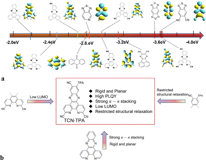 | ||
| Scheme 1 (a) Comparison of the LUMO levels of various acceptors applied for TADFs and calculated with B3LYP/6-31G(d); (b) the chemical structure and molecular design strategy of TCN-TPA. | ||
Results and discussion
The synthetic route to TCN-TPA is shown in Scheme S1 (ESI†). The condensation reaction between 4,5-diamino-4′-(bis(4-(tert-butyl)phenyl)amino)-4,5-dihydro-[1,1′-biphenyl]-2-carbonitrile and 2,9-dimethyl-1,10-phenanthroline-5,6-dione under acidic conditions produced pyrazine. The oxidation reaction with SeO2 converted the methyl group into an aldehyde. The following condensation reaction with hydroxylamine gave the oxime and then the dehydration reaction yielded the target compound, which was confirmed with 1H NMR spectroscopy, MALDI-TOF mass spectrometry, high resolution mass spectrometry (HRMS) and 13C NMR spectroscopy (Fig. S1–S7, ESI†). The HOMO of TCN-TPA determined with cyclic voltammetry was −5.28 eV (Fig. S8, ESI† and Table 1), which was comparable with those of TPA based TADFs.18–21 TCN-TPA demonstrated excellent thermostability at a decomposition temperature of 433 °C due to its robust structure (Fig. S9, ESI†).| Compound | λ abs (nm) | λ em (nm) | PLfl/phb (nm) | Φ PL,sol (%) | Φ PL,film (%) | PLFl,filmc (nm) | T g/Tdd (°C) | HOMO/LUMOe (eV) | E g (eV) | S1/T1g (eV) | ΔESTh (eV) |
|---|---|---|---|---|---|---|---|---|---|---|---|
| a Measured in toluene at 298 K. b Measured in toluene at 77 K. c Measured in CBP at 298 K with doping ratios at 9/24/30/50 wt%. d T g: glass transition temperature; Td: decomposition temperature. e HOMO was calculated from CV data; LUMO as calculated from the HOMO and Eg. f E g was calculated from the corresponding absorption cutoff. g Singlet/triplet energies (S1/T1) were calculated from fluorescence/phosphorescence onsets. h ΔEST = S1 – T1. | |||||||||||
| TCN-TPA | 396/556 | 720 | 660/678 | 18.7 | 30.5/11.0/8.7/5.7 | 730/775/789/803 | n.a./433 | −5.28/−3.33 | 1.95 | 2.17/1.97 | 0.20 |
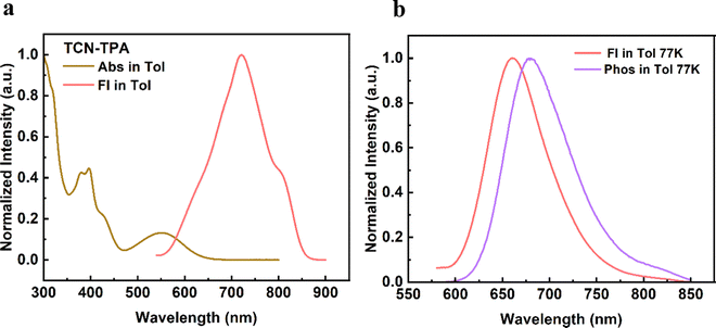
As shown in Fig. 1, TCN-TPA showed a weak CT absorption at 556 nm. Remarkably, an intensive emission peak at 720 nm was observed for TCN-TPA in toluene. So far there have been few reports on NIR TADF with native emission over 700 nm.12–14 Therefore, the introduction of multiple electron withdrawing groups (CN, pyrazine and pyridine) into TCN-TPA could effectively redshift the emission band. TCN-TPA showed a shoulder peak at around 800 nm. The donor unit 9,9-dimethyl-9,10-dihydroacridine is a flexible building block, which could have two possible conformations, namely, a planar form and a crooked form. Molecules constructed from this donor can thus have two corresponding conformations, and exhibited dual emission properties.22 The rigidity of the TCN unit could exclude the possibility of two stable conformations. The long-wavelength shoulder peak of TCN-TPA in toluene could originate from the contribution of different vibrational levels in the excited state. The S1 and T1 energy levels estimated from fluorescence (room temperature) and phosphorescence (77 K) onsets were 2.17 eV and 1.97 eV, respectively, giving ΔEST in toluene of 0.20 eV. Interestingly, the ΔESTs values for the thin films at 9/24/30/50 wt% doping ratios were 0.083/0.112/0.103/0.103 eV (Fig. S10, ESI†), which could enable the efficient reverse intersystem crossing (RISC) process.23 The emission band below 550 nm in the phosphorescence spectra of the doped thin-films samples could be assigned to the emission of the CBP host.24 Compared with the ΔEST in toluene, the reduction in ΔESTs for the doped films could be due to the enhanced intermolecular interaction in the solid state.11 The PLQYs for 9/24/30/50 wt% doped films were 30.5/11.0/8.7/5.7% with 730/775/789/803 nm emission peaks. As the doping ratio increased, the PLQYs decreased gradually due to the aggregation induced quenching effect. However, the PLQY of TCN-TPA in the 9 wt% doped thin film (30.5%) was higher than that in toluene (18.7%), which could be due to the restricted rotation and vibration in the solid state. This redshift in the emission spectra suggested the enhanced interaction between TCN-TPA molecules as the doping ratios increased.25 The transient PL measurements of the 9/24/30/50 wt% doped thin films revealed the prompt fluorescence with lifetimes (τp) in the range of 3.35–12.12 ns and the delayed fluorescence with lifetimes (τd) in the range of 9.6–50.1 μs (Fig. 2 and Table 2). Notably, the internal conversion decay rate from S1 to S0 (kIC, 3.87 × 10⁷ s−1–12.80 × 10⁷ s−1) was much higher than the corresponding radiative rate constant (krS, 5.94 × 10⁶ s−1–17.00 × 10⁶ s−1), partially due to the small energy gap between S1 and S0.
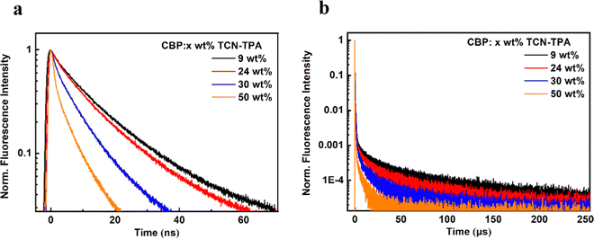 | ||
| Fig. 2 (a and b) Transient PL decay curves of TCN-TPA in x wt% doped CBP films (x = 9, 24, 30, and 50). | ||
| Compound | Doping ratio [wt%] | Φ PL [%] | Φ p/Φd [%] | τ p [ns] | τ d [μs] | k p [108 s−1] | k d [103 s−1] | k Sr [106 s−1] | k IC [107 s−1] | k ISC [107 s−1] | k RISC [103 s−1] |
|---|---|---|---|---|---|---|---|---|---|---|---|
| k p is the rate constant of prompt fluorescence decay; kd is the rate constant of delayed fluorescence decay; krS is the rate constant of radiative transition from S1 to S0; kIC is the internal conversion decay rate from S1 to S0; kISC is the rate constant of intersystem crossing; kRISC is the rate constant of reverse intersystem crossing. | |||||||||||
| TCN-TPA | 9 | 30.5 | 9.92/20.58 | 12.12 | 50.1 | 0.82 | 6.09 | 17.00 | 3.87 | 2.68 | 9.02 |
| 24 | 11.0 | 4.46/6.54 | 11.01 | 39.1 | 0.90 | 2.81 | 5.94 | 4.81 | 3.68 | 4.73 | |
| 30 | 8.7 | 4.10/4.59 | 6.65 | 21.2 | 1.50 | 4.10 | 6.91 | 7.25 | 7.08 | 7.76 | |
| 50 | 5.7 | 3.09/2.61 | 3.35 | 9.6 | 2.98 | 5.94 | 7.74 | 12.80 | 16.2 | 13.00 | |
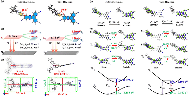
The electronic structure of TCN-TPA in toluene and in CBP (50 wt%) was studied by density functional theory. The calculation details are provided in the ESI.† As expected, large dihedral angles (46.8° in toluene and 49.2° in thin films) between TPA and TCN were detected, which led to wide separation of frontier orbitals with the HOMO on TPA and the LUMO on TCN (Fig. 3). The HOMO and LUMO of TCN-TPA in toluene were −5.86 eV and −3.22 eV, respectively. As shown in Fig. S11 (ESI†), TCN-TPA molecules adopted the head-to-tail (Dimer-1) and head-to-head (Dimer-2) packing patterns. Within these two types of dimers, the adjacent molecules were held together via π⋯π interaction to favor through-space electronic coupling in the doped thin film (50 wt%). As a result, TCN-TPA exhibited a narrow bandgap of 1.71 eV in the doped film with a HOMO of −5.13 eV and a LUMO of −3.42 eV. The S1/T1s values in toluene and in thin films were 1.85 eV/1.75 eV and 1.76 eV/1.70 eV, respectively. Therefore, the ΔEST in thin films (0.06 eV) was smaller than that in toluene (0.10 eV), which agreed well with the experimental result. Natural transition orbitals revealed a dominant CT character of S1 (LE contribution of 18.7%) and a hybridized local and charge transfer (HLCT)26 excited state of T1 (LE contribution of 52.8%) for TCN-TPA in toluene. In the doped films, the S1 and T1 of TCN-TPA are basically CT states with LE proportions of 16.8% and 23.9%, respectively. Due to the different transition characteristics of S1 and T1 in toluene, TCN-TPA demonstrated a larger spin–orbit coupling (SOC) matrix element (ξ(S1,T1) = 0.09 cm−1) in toluene than in thin films (ξ(S1,T1) = 0.08 cm−1). Since there was a big energy difference between S1 and T2, the T2 state could make an insignificant contribution during the RISC process though large ξ(S1,T2)s were achieved in toluene and in thin films. TCN-TPA showed a larger reorganization energy (estimated from the sum of λS1 and λS0) in toluene than in doped films due to the restricted structural relaxation in the solid state. The emission wavelengths in toluene and in 50 wt% doped films were calculated to be 745 nm and 800 nm, respectively.
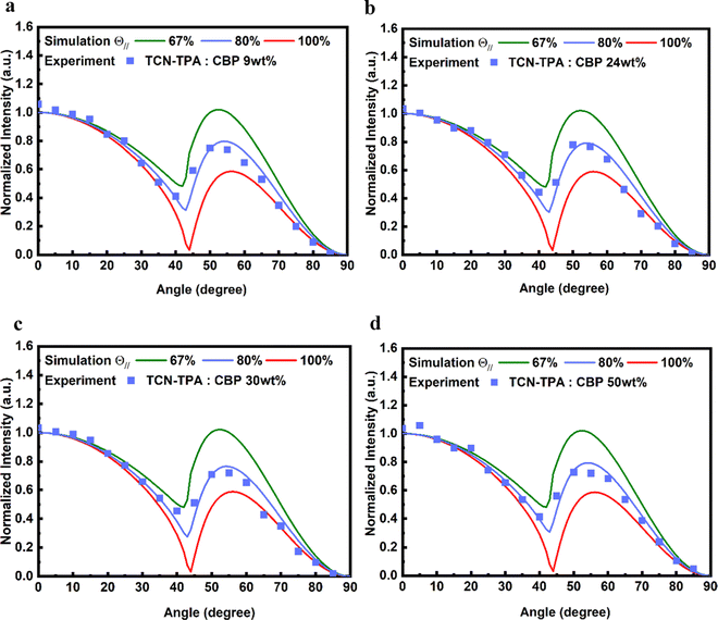
The side view of optimized geometry of the TCN-TPA molecule is shown in Fig. 3e, and the aspect ratios of TCN-TPA in toluene and in the solid state were 2.08 and 2.09, respectively. Thus, TCN-TPA can be considered as a rigid and linear molecule, which could enhance the horizontal emitting dipole ratio (Θ‖) and the optical out-coupling efficiency (Φout).27 The angle-resolved p-polarized PL intensity measurements indicated a high Θ‖of 80% for all the 9/24/30/50 wt% TCN-TPA doped films (Fig. 4). To study the electroluminescence (EL) performance of TCN-TPA, the devices were fabricated with the following configuration: sITO(115 nm)/MoO3(1 nm)/di-[4-(N,N-ditolyl-amino)-phenyl]-cyclohexane TAPC (x nm)/4,4′-bis(carbazol-9-yl)biphenyl CBP: TCN-TPA(20 nm)/4,6-bis(3,5-di(pyridin-3-yl)phenyl)-2-methylpyrimidine B3PYMBM(y nm)/LiF(1 nm)/Al, with x = 85 nm (S1), 105 nm (S2), 125 nm (S3) and y = 75 nm for 9 wt% doped devices; x = 95 nm (S4), 115 nm (S5), 135 nm (S6) and y = 80 nm for 24 wt% doped devices; x = 100 nm (S7), 120 nm (S8), 140 nm (S9) y = 80 nm for 30 wt% doped devices; x = 115 nm (S10), 135 nm (S11), 155 nm (S12) y = 90 nm for 50 wt% doped devices. The device structure, energy levels and molecular structures of functional layer materials are shown in Fig. S12 (ESI†). The device data are summarized in Table S1 (ESI†).
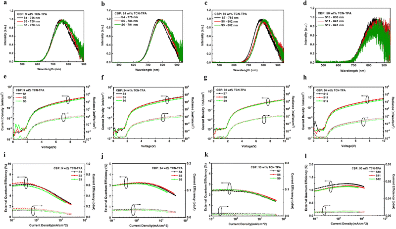
The EL properties of TCN-TPA are illustrated in Fig. 5. As the doping ratio increased, the EL peak varied in a wide range from 756 nm to 841 nm. Compared with the PL spectra, a redshift was observed in the EL spectra at a given doping ratio, which was ascribed to the microcavity effect of the device.28 The turn-on voltage with current density exceeding 10−5 mA cm−2 decreased gradually from 2.2 V to 1.8 V with the increase in the doping ratio from 9 wt% to 50 wt%. Lee and coworkers reported that the high doping ratio of TADF emitters could result in enhanced and balanced carrier transport in the emitting layer.29 The decrease in the turn-on voltage for TCN-TPA-based devices at the high doping ratios thus could be due to the reduced energy barrier during the charge injection and transport process. TCN-TPA demonstrated superior device performance with EQEs of 6.4/3.2/2.4/1.1% at 758/784/802/841 nm EL peaks. In addition to the high PLQY, the high Φout and exciton utilization efficiency also accounted for the state-of-the-art EL performance beyond 800 nm (Fig. 6). As shown in Table S2 (ESI†), the TADFs with EL emission over 800 nm used the TPA unit as the donor and the rigid and planar electron-withdrawing unit as the acceptor. These planar acceptor units could favor the intermolecular π⋯π interaction at higher doping ratios, thus red-shifting the emission wavelength. The Θ‖, refractive index (n) and extinction coefficient (k) of each functional layer material in our devices were used for calculating Φout.30 Assuming that the charge recombination efficiency was 100%,31 the Φouts and exciton utilization efficiencies were 34.8/35.8/34.2/33.7% and 62.0/84.2/83.6/71.0% (Table S3, ESI†), respectively, for the devices at the doping ratios of 9/24/30/50 wt%. The decrease in EQE at high brightness was due to the accumulation of T1 excitons and the consequent T1-associated quenching process in the emitting layer.
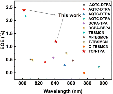 | ||
| Fig. 6 Reported maximum external quantum efficiencies for TADF OLEDs with EL peaks in the range of 800–900 nm. | ||
Conclusion
In summary, a NIR TADF emitter, TCN-TPA, was designed and prepared. The multiple sub-acceptor (CN group, pyrazine, and pyridine) strategy lowered the LUMO of TCN-TPA significantly and enabled the native emission in toluene over 700 nm. With the help of the strong intramolecular CT and intermolecular through-space coupling, the emission peak of TCN-TPA in doped thin films was pushed deep into the NIR region (over 800 nm). The rigid and linear configuration of TCN-TPA led to the high Θ‖(80%) and Φout (>33%). Thanks to the robust structure of TCN-TPA, the highly doped thin films with small ΔESTs (<0.12 eV) demonstrated high PLQYs (5.7–30.5%). As a result, TCN-TPA showed unprecedented EQEs of 2.4% at 802 nm and 1.1% at 841 nm.Author contributions
C. K. W., C. C. W. and J. F. conceived the original idea and secured funding. T. L. C., J. H. L., C. K. W., C. C. W. and J. F. supervised the project and drafted the manuscript. J. X. L., Y. T., Y.-w. S., C. H. C. and P. J. L. carried out the experiment, performed the data analysis and drafted the manuscript. X. W., K. Z. and C. K. W. performed the computations and helped to draft the manuscript. All authors read and approved the final manuscript.Conflicts of interest
The authors declare no conflicts of interest.Acknowledgements
The authors are grateful for the financial support from the National Natural Science Foundation of China (No. 21871199 and 21933002). This work was also supported by the Collaborative Innovation Centre of Suzhou Nano Science and Technology (Nano-CIC), the Priority Academic Program Development of Jiangsu Higher Education Institutions (PAPD), and the ‘‘111’’ Project of the State Administration of Foreign Experts Affairs of China. C.-C. Wu acknowledges the support from the Ministry of Science and Technology of Taiwan (MOST 110-2221-E-002-104-MY3 and 111-2221-E-002-031-MY3).References
- U. Balijapalli, Y.-T. Lee, B. S. B. Karunathilaka, G. Tumen-Ulzii, M. Auffray, Y. Tsuchiya, H. Nakanotani and C. Adachi, Angew. Chem., Int. Ed., 2021, 60, 19364–19373 CrossRef CAS PubMed.
- (a) H. Uoyama, K. Goushi, K. Shizu, H. Nomura and C. Adachi, Nature, 2012, 492, 234–238 CrossRef CAS PubMed; (b) Y. Liu, J. Yang, Z. Mao, D. Ma, Y. Wang, J. Zhao, S.-J. Su and Z. Chi, Adv. Opt. Mater., 2022, 11, 2201695 CrossRef; (c) Y. X. Hu, J. Miao, T. Hua, Z. Huang, Y. Qi, Y. Zou, Y. Qiu, H. Xia, H. Liu, X. Cao and C. Yang, Nat. Photonics, 2022, 16, 803–810 CrossRef CAS; (d) X. Wu, B.-K. Su, D.-G. Chen, D. Liu, C.-C. Wu, Z.-X. Huang, T.-C. Lin, C.-H. Wu, M. Zhu, E. Y. Li, W.-Y. Hung, W. Zhu and P.-T. Chou, Nat. Photonics, 2021, 15, 780–786 CrossRef CAS; (e) D. Zhang, Y. Wada, Q. Wang, H. Dai, T. Fan, G. Meng, J. Wei, Y. Zhang, K. Suzuki, G. Li, L. Duan and H. Kaji, Adv. Sci., 2022, 9, 2106018 CrossRef CAS PubMed.
- A. Zampetti, A. Minotto and F. Cacialli, Adv. Funct. Mater., 2019, 29, 1807623 CrossRef.
- Y. Xiao, H. Wang, Z. Xie, M. Shen, R. Huang, Y. Miao, G. Liu, T. Yu and W. Huang, Chem. Sci., 2022, 13, 8906–8923 RSC.
- D.-H. Kim, A. D’Aléo, X.-K. Chen, A. D. S. Sandanayaka, D. Yao, L. Zhao, T. Komino, E. Zaborova, G. Canard, Y. Tsuchiya, E. Choi, J. W. Wu, F. Fages, J.-L. Brédas, J.-C. Ribierre and C. Adachi, Nat. Photonics, 2018, 12, 98–104 CrossRef CAS.
- J. Kumsampao, C. Chaiwai, P. Chasing, T. Chawanpunyawat, S. Namuangruk, T. Sudyoadsuk and V. Promarak, Chem. – Asian J., 2020, 15, 3029–3036 CrossRef CAS PubMed.
- J. L. He, Y. Tang, K. Zhang, Y. Zhao, Y. C. Lin, C. K. Hsu, C. H. Chen, T. L. Chiu, J. H. Lee, C. K. Wang, C. C. Wu and J. Fan, Mater. Horiz., 2022, 9, 772–779 RSC.
- J.-F. Cheng, F.-C. Kong, K. Zhang, J.-H. Cai, Y. Zhao, C.-K. Wang, J. Fan and L.-S. Liao, Chem. Eng. J., 2022, 430, 132822 CrossRef CAS.
- S. Wang, X. Yan, Z. Cheng, H. Zhang, Y. Liu and Y. Wang, Angew. Chem., Int. Ed., 2015, 54, 13068–13072 CrossRef CAS PubMed.
- Y. Yuan, Y. Hu, Y.-X. Zhang, J.-D. Lin, Y.-K. Wang, Z.-Q. Jiang, L.-S. Liao and S.-T. Lee, Adv. Funct. Mater., 2017, 27, 1700986 CrossRef.
- J. Xue, Q. Liang, R. Wang, J. Hou, W. Li, Q. Peng, Z. Shuai and J. Qiao, Adv. Mater., 2019, 31, 1808242 CrossRef PubMed.
- D. G. Congrave, B. H. Drummond, P. J. Conaghan, H. Francis, S. T. E. Jones, C. P. Grey, N. C. Greenham, D. Credgington and H. Bronstein, J. Am. Chem. Soc., 2019, 141, 18390–18394 CrossRef CAS PubMed.
- Q. Liang, J. Xu, J. Xue and J. Qiao, Chem. Commun., 2020, 56, 8988–8991 RSC.
- Y. Yu, H. Xing, D. Liu, M. Zhao, H. H.-Y. Sung, I. D. Williams, J. W. Y. Lam, G. Xie, Z. Zhao and B. Z. Tang, Angew. Chem., Int. Ed., 2022, 61, e202204279 CAS.
- Q. Li, J. Xu, S. Tan, Y. Dai, J. Xue and J. Qiao, Org. Electron., 2022, 110, 106645 CrossRef CAS.
- J.-F. Cheng, Z.-H. Pan, K. Zhang, Y. Zhao, C.-K. Wang, L. Ding, M.-K. Fung and J. Fan, Chem. Eng. J., 2022, 430, 132744 CrossRef CAS.
- Y. Yu, Y. Hu, S. Yang, W. Luo, Y. Yuan, C. Peng, J. Liu, A. Khan, Z. Jiang and L. Liao, Angew. Chem., Int. Ed., 2020, 59, 21578–21584 CrossRef CAS PubMed.
- T. Yang, B. Y. Liang, Z. Cheng, C. L. Li, G. Y. Lu and Y. Wang, J. Phys. Chem. C, 2019, 123, 18585–18592 CrossRef CAS.
- H. Wang, B. Zhao, C. Qu, C. Duan, Z. Li, P. Ma, P. Chang, C. Han and H. Xu, Chem. Eng. J., 2022, 436, 135080 CrossRef CAS.
- Z. Cai, X. Wu, H. Liu, J. Guo, D. Yang, D. Ma, Z. Zhao and B. Z. Tang, Angew. Chem., Int. Ed., 2021, 60, 23635–23640 CrossRef CAS PubMed.
- T. Yang, J. Liang, Y. Cui, Z. Li, X. Peng, S.-J. Su, Y. Wang and C. Li, Adv. Opt. Mater., 2022, 11, 2201191 CrossRef.
- (a) K. Wang, Y.-Z. Shi, C.-J. Zheng, W. Liu, K. Liang, X. Li, M. Zhang, H. Lin, S.-L. Tao, C.-S. Lee, X.-M. Ou and X.-H. Zhang, ACS Appl. Mater. Interfaces, 2018, 10, 31515–31525 CrossRef CAS PubMed; (b) K. Wang, C.-J. Zheng, W. Liu, K. Liang, Y.-Z. Shi, S.-L. Tao, C.-S. Lee, X.-M. Ou and X.-H. Zhang, Adv. Mater., 2017, 29, 1701476 CrossRef PubMed.
- (a) J. Wang, J. Miao, C. Jiang, S. Luo, C. Yang and K. Li, Adv. Opt. Mater., 2022, 10, 2201071 CrossRef CAS; (b) G. Zhao, D. Liu, P. Wang, X. Huang, H. Chen, Y. Zhang, D. Zhang, W. Jiang, Y. Sun and L. Duan, Angew. Chem., Int. Ed., 2022, 61, e202212861 CAS.
- T. Tsuboi, H. Murayama, S.-J. Yeh and C.-T. Chen, Opt. Mater., 2007, 29, 1299–1304 CrossRef CAS.
- S.-P. Wang, Z. Cheng, X.-X. Song, X.-J. Yan, K.-Q. Ye, Y. Liu, G.-H. Yang and Y. Wang, ACS Appl. Mater. Interfaces, 2017, 9, 9892–9901 CrossRef CAS PubMed.
- (a) W. Z. Yuan, X. Bin, G. Chen, Z. H. He, J. Liu, H. L. Ma, Q. Peng, B. W. Wei, Y. Y. Gong, Y. W. Lu, G. F. He and Y. M. Zhang, Adv. Opt. Mater., 2017, 5, 1700466 CrossRef; (b) Y. Y. Pan, J. Huang, Z. M. Wang, S. T. Zhang, D. W. Yu and Y. G. Ma, RSC Adv., 2016, 6, 108404 RSC.
- (a) F. Tenopala-Carmona, O. S. Lee, E. Crovini, A. M. Neferu, C. Murawski, Y. Olivier, E. Zysman-Colman and M. C. Gather, Adv. Mater., 2021, 33, 2100677 CrossRef CAS PubMed; (b) X. Zeng, Y.-H. Huang, S. Gong, X. Yin, W.-K. Lee, X. Xiao, Y. Zhang, W. Zeng, C.-H. Lu, C.-C. Lee, X.-Q. Dong, C. Zhong, C.-C. Wu and C. Yang, Sci. China Mater., 2021, 64, 920–930 CrossRef CAS.
- (a) X. Gong, C.-H. Lu, W.-K. Lee, P. Li, Y.-H. Huang, Z. Chen, L. Zhan, C.-C. Wu, S.-L. Gong and C.-L. Yang, Chem. Eng. J., 2021, 405, 126663 CrossRef CAS; (b) B.-K. Wang, W.-K. Lee, K.-C. Lin, P.-J. Chen, Y.-H. Huang, S.-W. Wen, X. Zeng, F. Ni, S.-L. Gong, C.-L. Yang and C.-C. Wu, Org. Electron., 2021, 89, 106049 CrossRef CAS.
- J.-H. Tan, J.-M. Jin, W.-C. Chen, C. Cao, R. Wang, Z.-L. Zhu, Y. Huo and C.-S. Lee, ACS Appl. Mater. Interfaces, 2022, 14, 53120–53128 CrossRef CAS PubMed.
- R. Huang, H. Chen, H. Liu, Z. Zhuang, J. Wang, M. Yu, D. Yang, D. Ma, Z. Zhao and B. Z. Tang, Chem. Eng. J., 2022, 435, 134934 CrossRef CAS.
- L. Peng, J. Lv, S. Xiao, Y. Huo, Y. Liu, D. Ma, S. Ying and S. Yan, Chem. Eng. J., 2022, 450, 138339 CrossRef CAS.
Footnotes |
| † Electronic supplementary information (ESI) available. See DOI: https://doi.org/10.1039/d3tc00524k |
| ‡ These authors contributed equally to this work. |
| This journal is © The Royal Society of Chemistry 2023 |

