Boosted charge transfer and CO2 photoreduction by construction of S-scheme heterojunctions between Cs2AgBiBr6 nanosheets and two-dimensional metal–organic frameworks†
Ying
Jiang
,
Rui
Zhou
,
Zhijie
Zhang
 *,
Zhongliang
Dong
and
Jiayue
Xu
*
School of Materials Science and Engineering, Shanghai Institute of Technology, 100 Haiquan Road, Shanghai, 201418, P. R. China. E-mail: zjzhang@sit.edu.cn; xujiayue@sit.edu.cn
First published on 10th January 2023
Abstract
A lead-free Cs2AgBiBr6 double perovskite is emerging as a promising candidate to replace toxic lead halide perovskites because of its environmental friendliness and impressive stability. However, the applications of Cs2AgBiBr6 (CABB) in photocatalytic CO2 reduction are restricted by its poor charge separation and low CO2 capturing ability. Herein, we report a novel inorganic/organic hybrid photocatalyst by coupling two-dimensional (2D) CABB nanosheets (NSs) with 2D Ni-based metal–organic framework (Ni-MOF) NSs. Systematic studies suggest the formation of an S-scheme heterojunction between CABB and the Ni-MOF, which facilitates the separation of photogenerated charge carriers and preserves the high redox potential of the hybrid. The Ni-MOF also serves as a CO2 capturing agent to facilitate the surface reaction. These remarkable features endow the CABB/Ni-MOF hybrid with significantly enhanced photocatalytic CO2 reduction performance, which is 6.43 and 8.79 times higher than that of solitary CABB and Ni-MOF, respectively. This study offers a novel photocatalytic system based on lead-free double perovskites and MOFs, which sheds light on fabricating highly efficient photocatalysts for artificial photosynthesis.
Introduction
In view of the evergrowing energy crisis and environmental issues, there is an urgent need for exploiting efficient energy conversion technologies. Photocatalytic CO2 reduction into renewable fuels using clean and sustainable solar energy is an appealing approach to solve global warming and energy depletion simultaneously.1–5 To date, various semiconductor photocatalysts have been developed for CO2 reduction, such as TiO2,6,7 C3N4,8–10 CdS,11–13etc. However, the photocatalytic performance of the majority of semiconductors remains unsatisfactory for practical requirements because of their low charge separation efficiency and limited photo-absorption ability.Recently, metal halide perovskites (MHPs) have emerged as a class of new semiconductors, which have shown great prospects in solar energy conversion owing to their remarkable photoelectric properties, such as high extinction coefficients, wide absorption ranges, long charge diffusion lengths and tunable band gaps.14–17 Among various MHPs, the Cs2AgBiBr6 (CABB) double perovskite has become a research hotspot, owing to its desirable stability, high optical absorption coefficient and suitable band-edge potential.18–23 Specifically, compared to other Pb-free double perovskites, it shows higher stability toward moisture, air, light and heat.24 It has a relatively narrow band gap of 1.8–2.2 eV, which endows it with outstanding visible light harvesting ability.25 Last but not least, CABB has a negative enough conduction band position, which endows it with strong reduction power to convert CO2.26 Owing to the above advantages, CABB is regarded as a promising candidate for the photocatalytic CO2 reduction reaction. Despite these merits, the pristine CABB generally exhibits unsatisfactory catalytic activity due to poor charge separation and insufficient catalytic sites to adsorb/activate CO2 molecules. The construction of heterostructured photocatalysts by combining appropriate semiconductors with matched band alignments has been recognized as a significant strategy to achieve efficient photocatalytic activities.
Based on the band alignments of semiconductors, most of the heterostructures can be classified as type-I or type-II heterostructures. For Type-I heterostructures, although light harvesting is enhanced, this type of heterostructure is associated with a substantial charge recombination rate, which is unfavourable to photocatalysis.27 In the case of Type-II heterostructures, the valence band (VB) and conduction band (CB) positions of semiconductor 1 are higher than those of semiconductor 2. Hence, the charge carriers in the two semiconductors migrate in opposite directions, which leads to effective charge separation.28 However, the redox power of Type-II heterostructures is reduced because the photogenerated electrons transfer from the CB with a more negative potential to that with a less negative potential. To tackle these shortcomings, direct Z-scheme heterojunctions have been proposed since 2001,29 which can not only enable the effective spatial charge separation but also maintain the high redox ability of the heterostructure. Nevertheless, its mechanism is not well understood for the problems it faces with the traditional and all-solid-state Z-scheme heterojunctions. To address the above problems and drawbacks for charge transfer in type-II and Z-scheme systems, a new step-scheme (S-scheme) heterojunction concept was proposed by Yu et al.30 An S-scheme heterojunction is made up of two semiconductors with staggered band alignments, namely, the oxidation photocatalyst (OP) and the reduction photocatalyst (RP). When the OP and RP are in contact, the electrons of RP will spontaneously diffuse to OP, creating an internal electric field (IEF) directing from RP to OP, which facilitates the photogenerated electron transfer between the two semiconductors via band bending and Coulombic attraction. Subsequently, the powerless electrons and holes are recombined, while the useful photogenerated electrons in the CB of RP and holes in the VB of OP are reserved for photocatalytic reactions.31–33 Therefore, the S-scheme heterojunction is an excellent option to construct highly efficient photocatalysts.
Recently, metal–organic frameworks (MOFs) have received tremendous attention for energy-related applications, on account of their tailored porous structure, high specific surface area, readily accessible active sites, and controlled surface functionality.34–36 In addition to the inherent merits of bulk MOFs, two-dimensional (2D) MOF NSs possess many desirable advantages for catalysis, such as ultrathin thickness to guarantee rapid electron transfer and abundant exposed active sites to ensure high catalytic activity.37,38 These merits render 2D MOFs as ideal cocatalysts to make up for the deficiencies of CABB. Inspired by this, we demonstrate the coupling of 2D Ni-MOF NSs and 2D CABB NSs to construct a 2D/2D inorganic/organic hybrid photocatalyst. Such a unique structure with “face-to-face” contact can offer many advantages: (i) the large interface contact area can enhance the charge separation/transfer across the interfacial conjunction; (ii) the ultrathin thickness of the 2D nanosheets can shorten the transport distance of the photogenerated electrons and holes; (iii) there is generally strong electronic coupling between layers, which can contribute to the enhanced catalytic performance.39–41 In view of the significant advantages of MOFs and the 2D/2D heterostructure, it is anticipated that the construction of the 2D/2D CABB/Ni-MOF would afford a glorious photocatalyst for CO2 reduction.
In this study, the 2D/2D CABB/Ni-MOF inorganic/organic hybrid was successfully constructed via an electrostatic self-assembly approach. In the CABB/Ni-MOF photocatalytic system, the Ni-MOF not only boosted the charge separation efficiency of CABB but also facilitated the CO2 adsorption and activation ability of the hybrid. As a consequence, the CABB/Ni-MOF hybrid exhibited significantly improved photocatalytic CO2 reduction performance, which was about 6.43 and 8.79 times higher than that of solitary CABB and Ni-MOF, respectively. Deep insights into the charge transfer route in the as-designed heterojunction were unfolded by a series of characterization methods such as X-ray photoelectron spectroscopy (XPS), electron spin resonance (ESR), band structure analysis, etc. Based on various characterization methods, an S-scheme charge transfer mechanism in this hybrid was proposed. To the best of our knowledge, this is the first report on the 2D/2D perovskite/MOF hybrid for photocatalytic CO2 reduction. This study demonstrates that 2D MOFs can serve as promising cocatalysts to advance the CO2 photoreduction performance of perovskites, which further stimulates the potential of perovskites for solar-to-fuel conversions.
Experimental section
Chemicals
Nickel(II) chloride hexahydrate (NiCl2·6H2O, 98%), bismuth bromide (BiBr3, >99.9%), cesium carbonate (Cs2CO3, 99%), silver nitrate (AgNO3, 99.9%), terephthalic acid (1,4-BDC, 98%), N,N-dimethylformamide (DMF, 99.8%), triethylamine (TEA, 99%), 1-octadecene (ODE, 90%), oleic acid (OA, 90%), oleylamine (OAm, 90%), hydrobromic acid (HBr, 40%), tetrabutylammonium hexafluorophosphate (TBAPF6, >99.9%), ethyl acetate (EA, 99.8%), and ethanol (99.8%) were purchased from Sigma Aldrich and used as received.Fabrication of CABB NSs
The CABB NSs were fabricated according to a previously reported method by Liu et al.42 Typically, the Cs-oleate precursor was first prepared by mixing 825 mg of Cs2CO3 and 10 mL of OA in a 25 mL 3-necked flask, which was degassed at 120 °C for 30 min under vacuum, and heated to 150 °C for 1 hour under N2 flow. Meanwhile, 0.1 mmol BiBr3, 0.2 mmol AgNO3, 4 mL of ODE, 100 μL of HBr, 1 mL of OA and 1 mL of OAm were loaded into another 25 mL 3-necked flask. The mixture was degassed at 120 °C for 30 min under vacuum; then the temperature was increased to 200 °C for 10 min to dissolve the precursors. After the reaction system was cooled to ambient temperature, the Cs-oleate precursor was injected. Subsequently, the flask was reheated to 230 °C and maintained at this temperature for 10 min. Finally, the reaction mixture was cooled to room temperature, centrifuged, washed, and dried at 50 °C for 12 h under vacuum.Fabrication of Ni-MOF NSs
Ni-MOF NSs were fabricated according to a previous report by Rui et al.43 First, 125 mg of 1,4-BDC was dissolved in a mixture of 30 mL of DMF, 2 mL of ethanol, and 2 mL of deionized water with magnetic stirring. Then, 180 mg of NiCl2·6H2O was added to the above mixture, followed by a swift injection of 1 mL of TEA. After stirring the mixture for 10 min, a uniform colloidal suspension was formed, which was sealed and ultrasonicated continuously for 8 h at room temperature. Finally, the precipitate was centrifuged, washed with ethanol several times and dried at 60 °C for 10 h.Fabrication of the CABB/Ni-MOF hybrid
The CABB/Ni-MOF hybrid was fabricated via an electrostatic self-assembly process. In brief, 6 mg of Ni-MOF was added to 10 mL of EA and ultrasonicated for 10 min, and then a certain amount of CABB was added with stirring. Afterwards, the suspension was sealed and stirred constantly for 10 h. Finally, the precipitate was collected by centrifugation and dried at 50 °C for 12 h under vacuum. The mass percentages of CABB NSs in the hybrid were 30%, 40% and 50%, which were denoted as 0.3CABB/Ni-MOF, 0.4CABB/Ni-MOF and 0.5CABB/Ni-MOF, respectively.Characterization
The X-ray diffraction (XRD) pattern was tested on a Rigaku SmartLab SE X-ray diffractometer with Cu-Kα radiation. The transmission electron microscopy (TEM) characterization was conducted on a transmission electron microscope (JEOL JEM-2100F) at 200 kV equipped with an EDX detector. The UV-vis absorption spectra were recorded with the assistance of a PE Lambda 900 UV-vis spectrometer. Fourier transform infrared (FTIR) spectra were obtained from a Nicolet iN10 Frontier spectrometer. X-ray photoelectron spectroscopy (XPS) and VB-XPS data were collected on a photoelectron spectrometer (PerkinElmer). Photoluminescence (PL) and time resolved photoluminescence (TRPL) spectra were recorded on an Edinburgh FLS 9800 fluorescence spectrophotometer. Electron spin resonance (ESR) was carried out to detect the ˙OH and ˙O2− radicals using an ESR spectrometer (Bruker EMX PLUS) equipped with a 300 W Xe lamp as the irradiation source. For the measurement of ˙OH and ˙O2− radicals, the solvents used were acetonitrile/water (volume ratio of 200![[thin space (1/6-em)]](https://www.rsc.org/images/entities/char_2009.gif) :
:![[thin space (1/6-em)]](https://www.rsc.org/images/entities/char_2009.gif) 1) and saturated O2 acetonitrile solution, respectively. Photoelectrochemical characterization was performed on an electrochemical workstation (CHI 650E, Shanghai Chenhua) with a three-electrode setup, in which saturated Ag/AgCl, Pt plate and FTO glass with catalyst films were used as the reference, counter and working electrodes, respectively. The working electrode was prepared by spin-coating the slurry, which contained 10 mg of photocatalyst in a solution of 1 mL of hexane and 10 μL of Nafion, onto a 1 cm × 1 cm FTO glass and vacuum-dried at 80 °C for 1 h. A 300 W Xe lamp was used as the light source and the TBAPF6/EA solution (0.1 M) was used as the electrolyte.
1) and saturated O2 acetonitrile solution, respectively. Photoelectrochemical characterization was performed on an electrochemical workstation (CHI 650E, Shanghai Chenhua) with a three-electrode setup, in which saturated Ag/AgCl, Pt plate and FTO glass with catalyst films were used as the reference, counter and working electrodes, respectively. The working electrode was prepared by spin-coating the slurry, which contained 10 mg of photocatalyst in a solution of 1 mL of hexane and 10 μL of Nafion, onto a 1 cm × 1 cm FTO glass and vacuum-dried at 80 °C for 1 h. A 300 W Xe lamp was used as the light source and the TBAPF6/EA solution (0.1 M) was used as the electrolyte.
Photocatalytic CO2 reduction tests
Photocatalytic reduction of CO2 was performed in a gas-tight glass photoreactor, which was filled with 15 mg of photocatalyst and 10 mL of dried EA. Prior to irradiation, the system was vacuumed to get rid of oxygen and other gases in the reactor and refilled with high-purity CO2. Then, the light irradiation experiment was conducted under a 300 W Xe lamp as the simulated sunlight source. The gaseous products were collected and analyzed using a gas chromatograph (GC9700, Fuli Analytical Instrument Co., Ltd).Results and discussion
The 2D/2D CABB/Ni-MOF hybrid was prepared by the electrostatic self-assembly of the CABB NSs and Ni-MOF NSs, as illustrated in Fig. 1a. In order to check the feasibility of the electrostatic self-assembly approach, we measured the zeta potentials of CABB NSs and Ni-MOF NSs in EA. As shown in Fig. 1b, the zeta potentials of CABB NSs and Ni-MOF NSs were determined to be 19.0 and −11.2 mV, respectively. The opposite surface charge indicated that Coulomb electrostatic attraction existed between the corresponding NSs, which would provide the driving force for their assembly. Hence, the positively charged CABB NSs could be readily integrated with the negatively charged Ni-MOF NSs through electrostatic attraction, forming the 2D/2D CABB/Ni-MOF hybrid.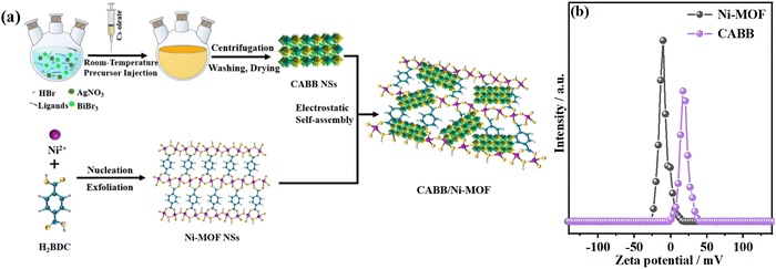 | ||
| Fig. 1 (a) Schematic illustration of the electrostatic self-assembly process of the 2D/2D CABB/Ni-MOF hybrid; (b) zeta potentials of CABB NSs and Ni-MOF NSs in EA. | ||
In order to corroborate the formation of the 2D/2D CABB/Ni-MOF hybrid, we used a series of characterization methods. XRD analysis was used to examine the phase and crystallinity of the samples. As presented in Fig. 2a, the pristine Ni-MOF exhibited characteristic diffraction peaks at 8.7°, 15.5° and 18.1°, corresponding to the (200), (![[2 with combining macron]](https://www.rsc.org/images/entities/char_0032_0304.gif) 01), and (400) planes of a monoclinic structure. This result is consistent with the previous report.43Fig. 2b illustrates the crystal structure of the Ni-MOF, which showed that Ni atoms were coordinated by six O atoms to form slightly distorted NiO6 octahedra. These octahedra were further connected with each other by corners/edges in the (200) planes, forming 2D metallic layers separated by BDC ligands. In the XRD pattern of CABB NSs, all the diffraction peaks corresponded to the standard cubic double perovskite structure (JCPDS No. 230901), and the sharp diffraction peaks indicated the high crystallinity of CABB NSs. The corresponding crystal structure of CABB is depicted in Fig. 2c, in which two toxic Pb2+ ions in CsPbBr3 were substituted by one Ag+ and one Bi3+, forming a double perovskite structure with two types of corner-sharing octahedra. As for the XRD patterns of CABB/Ni-MOF hybrids, all the characteristic peaks of CABB and Ni-MOF could be observed, indicating the successful construction of the CABB/Ni-MOF hybrid.
01), and (400) planes of a monoclinic structure. This result is consistent with the previous report.43Fig. 2b illustrates the crystal structure of the Ni-MOF, which showed that Ni atoms were coordinated by six O atoms to form slightly distorted NiO6 octahedra. These octahedra were further connected with each other by corners/edges in the (200) planes, forming 2D metallic layers separated by BDC ligands. In the XRD pattern of CABB NSs, all the diffraction peaks corresponded to the standard cubic double perovskite structure (JCPDS No. 230901), and the sharp diffraction peaks indicated the high crystallinity of CABB NSs. The corresponding crystal structure of CABB is depicted in Fig. 2c, in which two toxic Pb2+ ions in CsPbBr3 were substituted by one Ag+ and one Bi3+, forming a double perovskite structure with two types of corner-sharing octahedra. As for the XRD patterns of CABB/Ni-MOF hybrids, all the characteristic peaks of CABB and Ni-MOF could be observed, indicating the successful construction of the CABB/Ni-MOF hybrid.
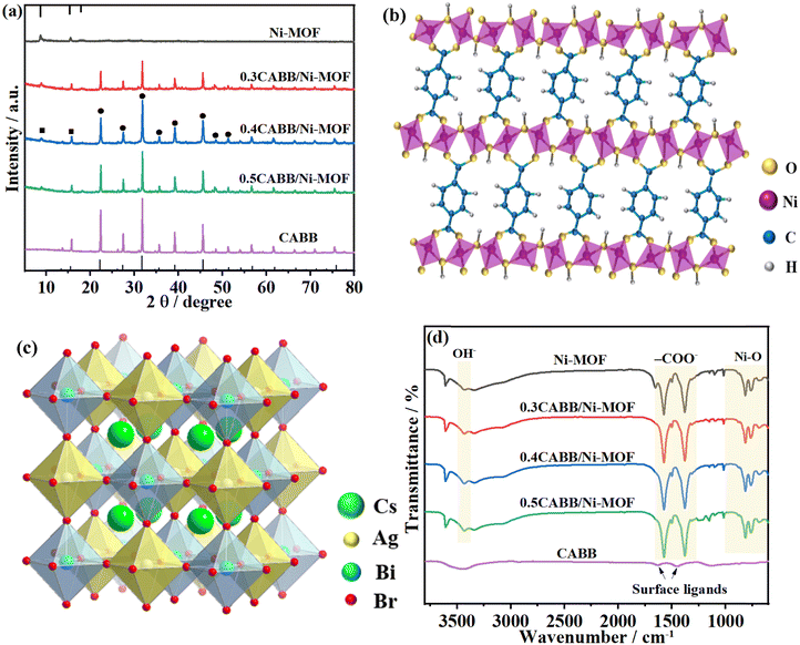 | ||
| Fig. 2 (a) XRD patterns of CABB NSs, Ni-MOF NSs, and the CABB/Ni-MOF hybrids; the crystal structure of (b) Ni-MOF and (c) CABB; (d) FTIR spectra of CABB NSs, Ni-MOF NSs, and the CABB/Ni-MOF hybrids. | ||
FTIR analyses were conducted to examine the functional groups in the formation of the samples, as shown in Fig. 2d. In the FTIR spectrum of the Ni-MOF, the two prominent peaks at 1369 and 1575 cm−1 corresponded to the symmetric and asymmetric –COO− stretching vibrations of the ligand coordinated to the Ni centre. The peaks at 3430 cm−1 were assigned to the OH− stretching vibration, and the appearance of peaks below 1000 cm−1 was ascribed to the Ni–O vibration, which confirmed that the ligands in 1,4-BDC were coordinated with the Ni centre to form metal–oxo bonds.44 In the FTIR spectrum of CABB, the peaks around 1500 cm−1 were attributed to the adsorbed organic ligands on the surface of CABB NSs. These peaks were hardly observed in the FTIR spectra of the CABB/Ni-MOF hybrids, which may be ascribed to their overlapping with the much stronger peaks from the Ni-MOF.
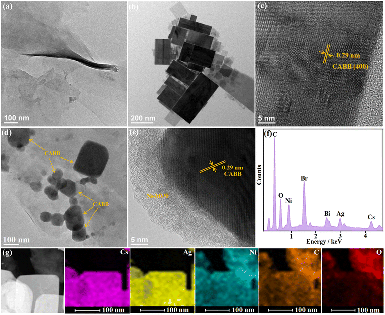
The TEM images of Ni-MOFs are presented in Fig. 3a and Fig. S1 (ESI†), which revealed that the prepared Ni-MOF exhibited flexible thin-layered nanosheet morphology with microscale lateral size. The elemental mapping images (Fig. S2, ESI†) revealed the uniformly distributed C, O, and Ni elements throughout the nanosheets. The TEM images in Fig. 3b and Fig. S3 (ESI†) indicate that CABB was composed of distinct rectangular nanosheets with an average edge length of 100–200 nm. High-resolution TEM (HRTEM) of an individual NS revealed the high crystallinity of CABB, with lattice fringes across the entire nanosheet (Fig. 3c). Moreover, lattice d-spacings of 0.29 nm could be clearly visualized, which was consistent with the (400) plane of the cubic double perovskite phase of CABB. In the TEM image of CABB/Ni-MOF (Fig. 3d), it can be clearly seen that the CABB NSs with a distinguished 2D rectangular structure were stacked on the ultrathin Ni-MOF NSs, forming a face-to-face contact structure. The HRTEM image further revealed a clear interface between the two distinguished NSs, with the interplanar spacings of 0.29 nm with respect to the (400) plane of CABB (Fig. 3e). The EDX spectrum of the CABB/Ni-MOF hybrid revealed the existence of Cs, Ag, Bi, Br, C, O, and Ni elements (Fig. 3f). Moreover, these elements were homogeneously distributed in the CABB/Ni-MOF hybrid, as shown in the elemental mapping images (Fig. 3g). All of the above investigations collaboratively illustrated the successful hybridization of CABB with the Ni-MOF, forming a 2D/2D face-to-face CABB/Ni-MOF structure.
The chemical states of the constituent elements and their chemical environment in CABB/Ni-MOF were examined by XPS analysis. Fig. S4 (ESI†) displays the XPS survey spectra of the samples, which revealed the coexistence of Cs, Ag, Bi, Br, C, O, and Ni elements within the CABB/Ni-MOF hybrid. Fig. 4a–f present the high-resolution XPS spectra of Cs 3d, Ag 3d, Bi 4f, Ni 2p, O 1s, and C 1s in CABB/Ni-MOF and the single counterparts. The Cs 3d XPS spectrum of CABB/Ni-MOF illustrated two peaks located at 724.0 and 738.0 eV, corresponding to the monovalent Cs (Fig. 4a). For the Ag 3d spectrum, the two peaks at 367.6 and 373.6 eV were assigned to the binding energies (BEs) of the Ag 3d5/2 and Ag 3d3/2, respectively (Fig. 4b). The Bi 4f spectrum exhibited two peaks at 159.0 and 164.3 eV, corresponding to the BEs of Bi 4f7/2 and Bi 4f5/2, respectively (Fig. 4c). After careful comparison with pristine CABB, it was found that the BEs of these elements had a positive shift to larger values. In contrast, an inverse shift was observed for the Ni 2p, O 1s, and C 1s spectra. Specifically, the BEs of Ni 2p2/3 and Ni 2p1/2 in CABB/Ni-MOF shifted negatively by 0.1 eV with respect to the pristine Ni-MOF (Fig. 4d), while the BEs of O 1s and C 1s in CABB/Ni-MOF shifted to lower values by 0.2 eV with respect to the Ni-MOF (Fig. 4e and 4f). In general, the decreased BE suggests an increased electron density and vice versa.45 Therefore, the above observation indicated that an electron depletion layer was formed in CABB, while an electron accumulation layer was formed in the Ni-MOF, resulting from the electron transfer from CABB to Ni-MOF upon the hybridization of these two components. The formation of a space-charge region would create an internal electric field (IEF) in the direction from CABB to Ni-MOF, facilitating the construction of an S-scheme CABB/Ni-MOF heterojunction.
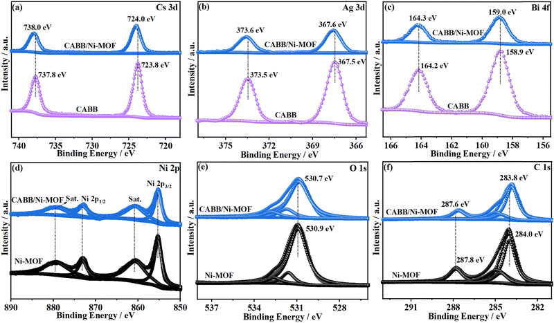 | ||
| Fig. 4 XPS spectra of (a) Cs 3d, (b) Ag 3d, (c) Bi 4f, (d) Ni 2p, (e) O 1s and (f) C 1s in CABB NSs, Ni-MOF NSs, and the CABB/Ni-MOF hybrid. | ||
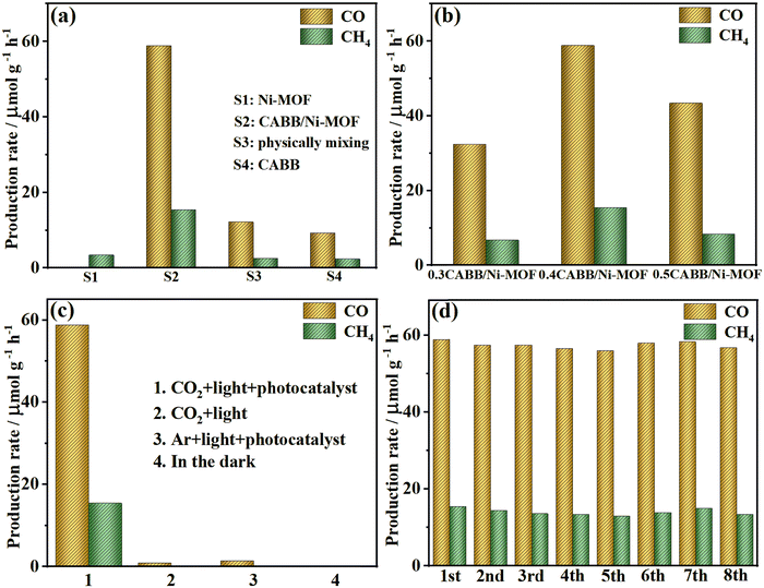
The photocatalytic performance of CABB, Ni-MOF, and the CABB/Ni-MOF hybrid was assessed by CO2 photoreduction under simulated solar light. As shown in Fig. S5 (ESI†) and Fig. 5a, only a slight amount of CH4 was generated by the pristine Ni-MOF, without the detection of CO, which is not surprising since its reduction potential is insufficient to reduce CO2 thermodynamically. For pristine CABB, a low gas production rate of 11.63 μmol g−1 h−1 (9.26 μmol g−1 h−1 for CO and 2.37 μmol g−1 h−1 for CH4) was detected, which was due to the severe charge recombination and poor charge separation. However, significantly increased CO and CH4 production rates were achieved upon the hybridization of these two components. Moreover, we prepared another sample with the same weight ratio by simple physical mixing and tested its photocatalytic activity for CO2 reduction. The result showed that the physically mixed sample exhibited much lower photocatalytic activity than the CABB/Ni-MOF hybrid, which indicated that the formation of an interface between CABB and Ni-MOF played a crucial role in promoting the charge separation. The optimized amount of CABB was investigated by altering the mass percentage of CABB in the CABB/Ni-MOF hybrid. As illustrated in Fig. 5b, the optimum photocatalytic performance was detected on the sample of 0.4 CABB/Ni-MOF, which achieved the highest production rates of CO (58.85 μmol g−1 h−1) and CH4 (15.43 μmol g−1 h−1). Further increasing the amount of CABB led to decreased production rates, although they were still higher than those of the pristine counterparts. This phenomenon was due to the reason that an optimized amount of CABB could enhance the photo-absorption ability of the CABB/Ni-MOF hybrid, while excess amount of CABB would shield the catalytic active sites for the photocatalytic reaction.
For better evaluation of the photocatalytic CO2 reduction performance, the rate of electrons’ production contributed to the photoreduction reaction (Relectron) which was calculated using the formula Relectron = 2RCO + 8RCH4. As shown in Fig. S6 (ESI†), and the highest Relectron value (241.14 μmol g−1 h−1) was achieved for the sample of 0.4 CABB/Ni-MOF, which was about 6.43 and 8.79 times more than that of pristine CABB (37.48 μmol g−1 h−1) and Ni-MOF (27.44 μmol g−1 h−1), respectively. Moreover, quantum efficiencies (QEs) of 0.4 CABB/Ni-MOF and pristine CABB were obtained at visible wavelengths of 420 and 450 nm. The result showed that the 0.4 CABB/Ni-MOF hybrid showed QEs of 0.042% and 0.025% at wavelengths of 420 and 450 nm, respectively, which were significantly higher than those of the pristine CABB (0.013% and 0.008%). The increased QE could be attributed to the enhanced charge-separation efficiency of the CABB/Ni-MOF hybrid. Moreover, the CO2 photoreduction performance of the CABB/Ni-MOF hybrid and other perovskite-based photocatalysts was compared, as listed in Table S1 (ESI†). It can be seen that the photocatalytic performance of the CABB/Ni-MOF hybrid is higher than most of the reported perovskite-based photocatalysts, which demonstrated a unique superiority of the developed CABB/Ni-MOF hybrid.
Furthermore, control experiments were conducted to confirm the origin of the produced gas, as shown in Fig. 5c. The results showed that no CO was detected in the absence of light illumination, indicating that light illumination was indispensable for the CO2 photoreduction reaction. In the case of Ar + photocatalyst + light illumination or CO2 + light illumination, a slight amount of CO was detected, which may result from the partial photooxidation of EA. Noticeably, upon the addition of CO2 and CABB/Ni-MOF under visible illumination, significant CO and CH4 productions were detected, implying that the produced gases were originated from the photocatalytic CO2 reduction by the developed CABB/Ni-MOF hybrid as a photocatalyst. The origin of the reductive products was further affirmed by a 13CO2 isotope trace experiment. As shown in Fig. S7 (ESI†), the mass spectra displayed strong signals at m/z = 29 and m/z = 17, which could be readily assigned to 13CO and 13CH4, respectively. This result provided additional evidence that the gaseous products came from the photocatalytic reduction of CO2.
In addition, the photocatalytic durability of the CABB/Ni-MOF hybrid was investigated by eight consecutive photocatalytic recycling runs. As shown in Fig. 5d, the catalyst exhibited no obvious decay of photocatalytic activity after eight testing cycles, suggesting the desired cycling stability of the CABB/Ni-MOF hybrid. Moreover, the XRD, TEM and FTIR spectra of the catalyst after the photocatalytic reaction were characterized. As shown in Fig. S8–S10 (ESI†), no perceptible changes in the crystal structure, morphology or chemical functional groups could be observed, further confirming the long-term photostability of the CABB/Ni-MOF hybrid.
The superiority of the designed 2D/2D CABB/Ni-MOF hybrid was further demonstrated by comparison with that of the 0D/2D CABB/Ni-MOF hybrid. Fig. S11 (ESI†) displays the TEM image of the fabricated 0D/2D CABB/Ni-MOF hybrid, which indicated that cubic-shaped CABB quantum dots (QDs) were decorated on the 2D Ni-MOF NSs, forming a 0D/2D CABB/Ni-MOF heterostructure. The evaluation of CO2 photoreduction activity indicated that the gases’ production rate was 22.84 μmol g−1 h−1 (18.63 μmol g−1 h−1 for CO and 4.21 μmol g−1 h−1 for CH4) for the 0D/2D CABB/Ni-MOF hybrid (Fig. S12, ESI†), which was much lower than that of the 2D/2D counterpart. The remarkable CO2 photoreduction performance of the 2D/2D CABB/Ni-MOF hybrid suggested that the photocatalytic activity could be regulated by rationally tuning the dimension structures of the as-constructed heterojunctions.
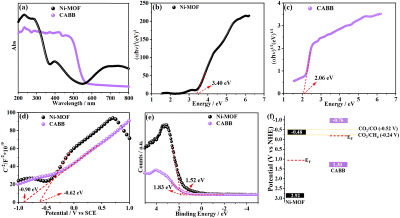
In order to probe the charge transfer direction in the CABB/Ni-MOF hybrid, the energy band structures of CABB and Ni-MOF are highly important. First, we examined the bandgaps (Eg) of CABB and Ni-MOF by Tauc plots, which were obtained from their corresponding optical absorption spectra (Fig. 6a). As shown in Fig. 6b and c, the bandgaps were determined to be 3.40 eV for the Ni-MOF and 2.06 eV for CABB, respectively. Meanwhile, the conduction bands (CBs) of CABB and Ni-MOF were derived by analyzing their Mott–Schottky (M–S) plots, which were determined to be at −0.76 and −0.48 V vs. the normal hydrogen electrode (NHE), respectively (Fig. 6d). Accordingly, the valence bands (VBs) of CABB and Ni-MOF were calculated using the formula EVB = ECB + Eg, which were determined to be at 1.30 and 2.92 V vs. NHE, respectively. Subsequently, the Fermi levels (EF) of the samples with respect to the VB were evaluated by VB-XPS spectra. According to Fig. 6e, the energy gap between the EF and VB was 1.52 eV for CABB and 1.83 eV for the Ni-MOF, respectively. On the basis of the obtained data, the band structures of CABB and Ni-MOF are shown in Fig. 6f. It should be noted that the energy band configurations of CABB and Ni-MOF are staggered, and EF of CABB locates more negatively than that of the Ni-MOF, meeting the requirements for the formation of an S-scheme heterojunction.
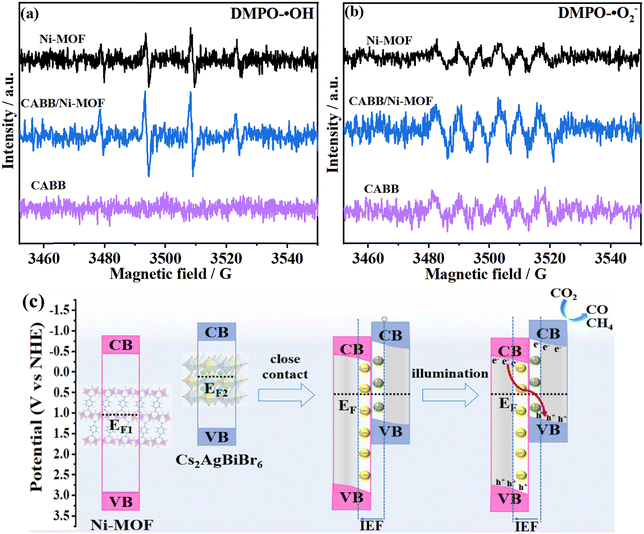
The charge transfer direction in the CABB/Ni-MOF hybrid was further evidenced by the ESR measurement, in which 5,5-dimethyl-1-pyrroline N-oxide (DMPO) was used as a trapping agent. As shown in Fig. 7a, four DMPO-˙OH peaks (relative intensities: 1![[thin space (1/6-em)]](https://www.rsc.org/images/entities/char_2009.gif) :
:![[thin space (1/6-em)]](https://www.rsc.org/images/entities/char_2009.gif) 2
2![[thin space (1/6-em)]](https://www.rsc.org/images/entities/char_2009.gif) :
:![[thin space (1/6-em)]](https://www.rsc.org/images/entities/char_2009.gif) 2
2![[thin space (1/6-em)]](https://www.rsc.org/images/entities/char_2009.gif) :
:![[thin space (1/6-em)]](https://www.rsc.org/images/entities/char_2009.gif) 1) were detected for the Ni-MOF and CABB/Ni-MOF hybrid, while no DMPO-˙OH signal could be detected for pristine CABB, which was presumable because its VB potential is not positive enough for the oxidation of H2O. For the ESR spectra of DMPO-˙O2− radicals (Fig. 7b), both pristine CABB and Ni-MOF displayed characteristic DMPO-˙O2− peaks, owing to the more negative CB potentials of both samples than that of O2/˙O2− (−0.33 eV, vs. NHE).46 It should be mentioned that the CABB/Ni-MOF hybrid exhibited stronger DMPO-˙OH and DMPO-˙O2− signals than those of the pristine counterparts, which indicated the accumulation of photogenerated electrons and holes in the hybrid. The results of ESR characterization provided strong evidence for the S-scheme charge transfer mechanism between CABB and Ni-MOF.
1) were detected for the Ni-MOF and CABB/Ni-MOF hybrid, while no DMPO-˙OH signal could be detected for pristine CABB, which was presumable because its VB potential is not positive enough for the oxidation of H2O. For the ESR spectra of DMPO-˙O2− radicals (Fig. 7b), both pristine CABB and Ni-MOF displayed characteristic DMPO-˙O2− peaks, owing to the more negative CB potentials of both samples than that of O2/˙O2− (−0.33 eV, vs. NHE).46 It should be mentioned that the CABB/Ni-MOF hybrid exhibited stronger DMPO-˙OH and DMPO-˙O2− signals than those of the pristine counterparts, which indicated the accumulation of photogenerated electrons and holes in the hybrid. The results of ESR characterization provided strong evidence for the S-scheme charge transfer mechanism between CABB and Ni-MOF.
As illustrated in Fig. 7c, when the Ni-MOF and CABB are contacted to form the CABB/Ni-MOF hybrid, the electrons in CABB will slide across the interface to the Ni-MOF spontaneously due to the higher Fermi level of the former. This process will reach an equilibrium until the alignment of their Fermi levels, establishing a space charge layer at the interface of the CABB/Ni-MOF hybrid. In the space charge layer, CABB is positively charged while the Ni-MOF is negatively charged, building an IEF directing from CABB to Ni-MOF. Owing to the driving force provided by the IEF, the photoinduced electrons in the CB of the Ni-MOF will recombine with the photoinduced holes in the VB of CABB, while the powerful electrons and holes are left on CABB and Ni-MOF, respectively. This S-scheme charge transfer mode can bring about two significant advantages: one is the efficient separation of photoinduced charge carriers and the other is the preservation of strong redox potentials of the CABB/Ni-MOF hybrid.
To gain insight into the separation efficiency of the photoinduced charge carriers in the CABB/Ni-MOF hybrid, photoelectrochemical (PEC) measurements were carried out. Fig. 8a depicts the transient photocurrent responses of the samples, which revealed that the CABB/Ni-MOF hybrids exhibited notably higher photocurrents than pristine CABB and Ni-MOF, suggesting the promoted charge transfer of the CABB/Ni-MOF hybrid. Significantly, the 0.4 CABB/Ni-MOF sample exhibited the highest photocurrent, which was consistent with its optimum photocatalytic performance. Moreover, Fig. 8b presents the electrochemical impedance spectra (EIS) of the samples, which shows that the CABB/Ni-MOF hybrids displayed smaller semicircles of the Nyquist plots than those of pristine CABB and Ni-MOF. This result indicated that the charge resistance of the CABB/Ni-MOF hybrid is substantially reduced, leading to fast separation and transfer of the photoinduced charge carriers.
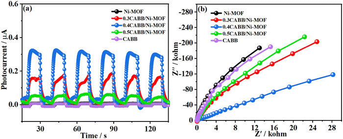 | ||
| Fig. 8 (a) Photocurrent responses and (b) the electrochemical impedance spectra (EIS) of CABB NSs, Ni-MOF NSs, and the CABB/Ni-MOF hybrids. | ||
Photoluminescence (PL) spectra were also recorded to understand the charge recombination dynamics and charge carrier separation efficiencies of the studied photocatalysts. As shown in Fig. 9a, the PL intensity of the CABB/Ni-MOF hybrid was much lower than that of pristine CABB, which indicated a low photogenerated electron–hole recombination rate and efficient charge separation of the CABB/Ni-MOF hybrid. Time-resolved photoluminescence (TRPL) spectra (Fig. 9b) showed that the CABB/Ni-MOF hybrid exhibited shorter decay time than pristine CABB, which also signified the high charge separation ability of the CABB/Ni-MOF hybrid.
Considering that the CO2 photoreduction reaction strongly relies on surface reactions between the chemisorbed CO2 molecules and the photogenerated electrons, the CO2 capturing ability of the catalyst is another crucial factor determining the final photocatalytic performance. Therefore, we investigated the CO2 adsorption behavior of CABB, Ni-MOF and the CABB/Ni-MOF hybrid by adsorption/desorption plots at 273 K. As shown in Fig. 9c, pristine CABB exhibited poor CO2 capturing ability, with a CO2 uptake of only 2.21 cm3 g−1. In stark contrast, the Ni-MOF and the CABB/Ni-MOF hybrid displayed remarkable CO2 capturing behavior, with a CO2 uptake of 8.75 and 4.69 cm3 g−1, respectively. The significantly improved CO2 adsorption capacity of the CABB/Ni-MOF hybrid could be attributed to the introduction of the Ni-MOF, which has a large surface area and contributes to the CO2 adsorption of the catalyst.
According to the above discussions, the mechanism for the enhanced CO2 photoreduction performance of the CABB/Ni-MOF hybrid was proposed, as illustrated in Fig. 10: driven by the electrostatic interaction between the positively charged CABB NSs and negatively charged Ni-MOF NSs, a 2D/2D CABB/Ni-MOF hybrid with “surface-to-surface” contact was constructed. Such a unique 2D/2D heterojunction can increase the interface contact area, which benefits the separation and transport of charge carriers between the NSs. As discussed above, the charge carriers in the CABB/Ni-MOF hybrid transfer in an S-scheme mode, in which the pointless electrons in the CB of the Ni-MOF recombine with the holes in the VB of CABB, while the powerful electrons and holes are accumulated in the CB of CABB and VB of the Ni-MOF, respectively. As such, efficient charge separation between CABB and Ni-MOF is realized, while retaining the highly reductive electrons at the CABB side for subsequent CO2 reduction. In addition, profiting from the large surface area of the Ni-MOF, the CABB/Ni-MOF hybrid possesses remarkable CO2 capturing ability, which also contributes to the photocatalytic CO2 reduction process. In light of the large interface contact area, effective spatial charge separation, high reduction potential preservation, as well as the enhanced CO2 adsorption, it is not surprising that the developed 2D/2D CABB/Ni-MOF hybrid exhibits excellent photocatalytic CO2 reduction performance.
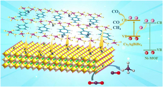 | ||
| Fig. 10 Scheme illustrating the interfacial electron transfer process and the CO2 photoreduction mechanism of the CABB/Ni-MOF hybrid. | ||
Conclusions
In conclusion, a 2D/2D CABB/Ni-MOF hybrid was fabricated via electrostatic interactions between the oppositely charged CABB and Ni-MOF NSs. A comprehensive investigation including XPS spectra, band structure analysis, and ESR measurement verified that the charge carriers in the CABB/Ni-MOF hybrid transferred via a unique S-scheme mode. The developed CABB/Ni-MOF hybrid was applied for photocatalytic CO2 reduction under simulated solar light. Interestingly, a remarkable electron consumption rate high up to 241.14 μmol g−1 h−1 was achieved for the optimal CABB/Ni-MOF hybrid, which was 6.43 and 8.79 times higher than that of pristine CABB and Ni-MOF, respectively. The substantially enhanced photocatalytic performance of the CABB/Ni-MOF hybrid was attributed to the effective separation of charge carriers and preservation of high reduction potential brought by the unique S-scheme heterojunction, as well as the improved CO2 adsorption capacity. These findings pave an avenue for modulating the photocatalytic properties of lead-free semiconductors, which show great potential in various energy-related applications.Conflicts of interest
The authors declare that they have no known competing financial interests in connection with the work submitted.Acknowledgements
This work was financially supported by the National Natural Science Foundation of China (51972213), the Natural Science Foundation of Shanghai (22ZR1460700), and the Collaborative Innovation Fund of Shanghai Institute of Technology (XTCX2021-7, XTCX2022-28).References
- W. Tu, Y. Zhou and Z. Zou, Adv. Mater., 2014, 26, 4607–4626 CrossRef CAS PubMed.
- K. Li, B. Peng and T. Peng, ACS Catal., 2016, 6, 7485–7527 CrossRef CAS.
- J. Ran, M. Jaroniec and S. Z. Qiao, Adv. Mater., 2018, 30, 1704649 CrossRef PubMed.
- T. Kong, Y. Jiang and Y. Xiong, Chem. Soc. Rev., 2020, 49, 6579–6591 RSC.
- J. Y. Do, N. Son, R. K. Chava, K. K. Mandari, S. Pandey, V. Kumaravel, T. S. Senthil, S. W. Joo and M. Kang, ACS Sustainable Chem. Eng., 2020, 8, 18646–18660 CrossRef CAS.
- A. Dhakshinamoorthy, S. Navalon, A. Corma and H. Garcia, Energy Environ. Sci., 2012, 5, 9217–9233 RSC.
- S. N. Habisreutinger, L. Schmidt-Mende and J. K. Stolarczyk, Angew. Chem., Int. Ed., 2013, 52, 7372–7408 CrossRef CAS PubMed.
- S. W. Cao, J. X. Low, J. G. Yu and M. Jaroniec, Adv. Mater., 2015, 27, 2150–2176 CrossRef CAS PubMed.
- Q. Li, S. Wang, Z. Sun, Q. Tang, Y. Liu, L. Wang, H. Wang and Z. Wu, Nano Res., 2019, 12, 2749–2759 CrossRef CAS.
- Z. Jiang, W. Wan, H. Li, S. Yuan, H. Zhao and P. K. Wong, Adv. Mater., 2018, 30, 1706108 CrossRef PubMed.
- L. Cheng, Q. J. Xiang, Y. L. Liao and H. W. Zhang, Energy Environ. Sci., 2018, 11, 1362–1391 RSC.
- Q. Mu, Y. Su, Z. Wei, H. Sun, Y. Lian, Y. Dong, P. Qi, Z. Deng and Y. Peng, J. Catal., 2021, 397, 128–136 CrossRef CAS.
- Z. Zhu, J. Qin, M. Jiang, Z. Ding and Y. Hou, Appl. Surf. Sci., 2017, 391, 572–579 CrossRef CAS.
- J. Song, J. Li, L. Xu, J. Li, F. Zhang, B. Han, Q. Shan and H. Zeng, Adv. Mater., 2018, 30, 1800764–1800770 CrossRef PubMed.
- H. L. Wu, X. B. Li, C. H. Tung and L. Z. Wu, Adv. Mater., 2019, 31, 1900709 CrossRef PubMed.
- J. Liang, D. Chen, X. Yao, K. Zhang, F. Qu, L. Qin, Y. Huang and J. Li, Small, 2020, 16, 1903398 CrossRef CAS PubMed.
- Z. J. Zhang, Y. Jiang, M. Y. Shu, L. Li, Z. L. Dong and J. Y. Xu, J. Phys. Chem. Lett., 2021, 12, 5864–5870 CrossRef CAS PubMed.
- A. Slavney, T. Hu, A. Lindenberg and H. Karunadasa, J. Am. Chem. Soc., 2016, 138, 2138–2141 CrossRef CAS PubMed.
- L. Zhou, Y. F. Xu, B. X. Chen, D. B. Kuang and C. Y. Su, Small, 2018, 14, 1703762 CrossRef PubMed.
- Z. Zhang, Y. Liang, H. Huang, X. Liu, Q. Li, L. Chen and D. Xu, Angew. Chem., Int. Ed., 2019, 58, 7263–7267 CrossRef CAS PubMed.
- T. Wang, D. Yue, X. Li and Y. Zhao, Appl. Catal., B, 2020, 268, 118399 CrossRef CAS.
- S. Kumar, I. Hassan, M. Regue, S. Carrero, E. Rattner, M. Isaacs and S. Eslava, J. Mater. Chem. A, 2021, 9, 12179–12187 RSC.
- D. Wu, Y. Tao, Y. Huang, B. Huo, X. Zhao, J. Yang, X. Jiang, Q. Huang, F. Dong and X. Tang, J. Catal., 2021, 397, 27–35 CrossRef CAS.
- H. Huang, B. Pradhan, J. Hoens, M. B. J. Roeffaers and J. A. Steele, ACS Energy Lett., 2020, 5, 1107–1123 CrossRef CAS.
- Z. Zhang, Y. Jiang, Z. Dong, Y. Chu and J. Xu, Inorg. Chem., 2022, 61, 16028–16037 CrossRef CAS PubMed.
- Y. Wang, H. Huang, Z. Zhang, C. Wang, Y. Yang, Q. Li and D. Xu, Appl. Catal., B, 2021, 282, 119570 CrossRef CAS.
- R. K. Chava, N. Son, Y. S. Kimb and M. Kang, Inorg. Chem. Front., 2020, 7, 2818–2832 RSC.
- R. K. Chava, N. Son and M. Kang, Appl. Surf. Sci., 2021, 556, 149731 CrossRef CAS.
- M. Grätzel, Nature, 2001, 414, 338–344 CrossRef PubMed.
- Q. Xu, L. Zhang, B. Cheng, J. Fan and J. Yu, Chem, 2020, 6, 1543–1559 CAS.
- R. K. Chava, N. Son and M. Kang, J. Colloid Interface Sci., 2022, 627, 247–260 CrossRef CAS PubMed.
- Z. Wang, B. Cheng, L. Zhang, J. Yu, Y. Li, S. Wageh and A. Al-Ghamdi, Chin. J. Catal., 2022, 43, 1657–1666 CrossRef CAS.
- F. Xu, K. Meng, B. Cheng, S. Wang, J. Xu and J. Yu, Nat. Commun., 2020, 11, 4613 CrossRef CAS PubMed.
- T. Song, L. Zhang, P. Zhang, J. Zeng, T. Wang, A. Ali and H. Zeng, J. Mater. Chem. A, 2017, 5, 6013–6018 RSC.
- W. Zhu, C. Zhang, Q. Li, L. Xiong, R. Chen, X. Wan, Z. Wang, W. Chen, Z. Deng and Y. Peng, Appl. Catal., B, 2018, 238, 339–345 CrossRef CAS.
- X. Deng, R. Li, S. Wu, L. Wang, J. Hu, J. Ma, W. Jiang, N. Zhang, X. Zheng, C. Gao, L. Wang, Q. Zhang, J. Zhu and Y. Xiong, J. Am. Chem. Soc., 2019, 141, 10924–10929 CrossRef CAS PubMed.
- M. Ko, L. Mendecki and K. A. Mirica, Chem. Commun., 2018, 54, 7873–7891 RSC.
- M. Zhao, Y. Huang, Y. Peng, Z. Huang, Q. Ma and H. Zhang, Chem. Soc. Rev., 2018, 47, 6267–6295 RSC.
- F. X. Xiao, M. Pagliaro, Y. J. Xu and B. Liu, Chem. Soc. Rev., 2016, 45, 3088–3121 RSC.
- S. Cao, B. Shen, T. Tong, J. Fu and J. Yu, Adv. Funct. Mater., 2018, 28, 1800136 CrossRef.
- Y. X. Zhao, S. Zhang, R. Shi, G. I. N. Waterhouse, J. W. Tang and T. R. Zhang, Mater. Today, 2020, 34, 78–91 CrossRef CAS.
- Z. Liu, H. Yang, J. Wang, Y. Yuan, K. Hills-Kimball, T. Cai, P. Wang, A. Tang and O. Chen, Nano Lett., 2021, 21, 1620–1627 CrossRef CAS PubMed.
- K. Rui, G. Zhao, Y. Chen, Y. Lin, Q. Zhou, J. Chen, J. Zhu, W. Sun, W. Huang and S. Dou, Adv. Funct. Mater., 2018, 28, 1801554 CrossRef.
- P. Thangasamy, S. Shanmuganathan and V. Subramanian, Nanoscale Adv., 2020, 2, 2073–2079 RSC.
- P. Xia, S. Cao, B. Zhu, M. Liu, M. Shi, J. Yu and Y. Zhang, Angew. Chem., Int. Ed., 2020, 59, 5218–5225 CrossRef CAS PubMed.
- C. Cheng, B. He, J. Fan, B. Cheng, S. Cao and J. Yu, Adv. Mater., 2021, 33, 2100317 CrossRef CAS PubMed.
Footnote |
| † Electronic supplementary information (ESI) available. See DOI: https://doi.org/10.1039/d2tc04284c |
| This journal is © The Royal Society of Chemistry 2023 |

