 Open Access Article
Creative Commons Attribution 3.0 Unported Licence
Effects of the rigid and sterically bulky structure of non-fused nonfullerene acceptors on transient photon-to-current dynamics†
Seihou
Jinnai
 *a,
Kasumi
Murayama
b,
Keisuke
Nagai
a,
Megumi
Mineshita
c,
Kosaku
Kato
 d,
Azusa
Muraoka
 c,
Akira
Yamakata
 *d,
Akinori
Saeki
 ef,
Yasuhiro
Kobori
 *bg and
Yutaka
Ie
 *af
*af
aThe Institute of Scientific and Industrial Research (SANKEN), Osaka University, 8-1 Mihogaoka, Osaka 567-0047, Ibaraki, Japan. E-mail: jinnai@sanken.osaka-u.ac.jp; yutakaie@sanken.osaka-u.ac.jp
bDepartment of Chemistry, Graduate School of Science, Kobe University, 1-1 Rokkodai-cho, Nada-ku, Kobe 657-8501, Japan
cDepartment of Mathematics, Physics and Computer Science, Japan Women's University, 2-8-1, Mejirodai, Bunkyo-ku, Tokyo 112-8681, Japan
dGraduate School of Natural Science & Technology, Okayama University, 3-1-1 Tsushima-naka, Okayama 700-8530, Japan. E-mail: yamakata@okayama-u.ac.jp
eDepartment of Applied Chemistry, Graduate School of Engineering, Osaka University, 2-1 Yamadaoka, Suita, Osaka 565-0871, Japan
fInnovative Catalysis Science Division, Institute for Open and Transdisciplinary Research Initiatives (OTRI), Osaka University, 2-1 Yamadaoka, Suita, Osaka 565-0871, Japan
gMolecular Photoscience Research Center, Kobe University, 1-1 Rokkodai-cho, Nada-ku, Kobe 657-8501, Japan. E-mail: ykobori@kitty.kobe-u.ac.jp
First published on 9th August 2022
Abstract
Non-fused electron-accepting π-conjugated compounds have been investigated recently for application to nonfullerene acceptors (NFAs) in organic solar cells (OSCs). However, the establishment of rational molecular design for non-fused NFAs is still lagging because the influence of flexible non-fused structures on the dynamics of electron–hole pairs in OSCs is not entirely understood. In this study, we utilized cyclopentene-annelated thiophene with spiro-substituted 2,7-bis(2-ethylhexyl)fluorene (FT) as a rigid and sterically bulky linker unit and developed a non-fused NFA (TT–FT–DCI) containing FT units. Photophysical measurements indicated that the introduction of the FT unit leads to the formation of rigid molecular structure. OSCs based on donor polymer (PBDB-T) and TT–FT–DCI showed an improved power conversion efficiency of 7.13% due to the increase in the short-circuit current density and fill factor. Time-resolved optical and microwave spectroscopies showed that the FT unit contributes to the long lifetimes of excited state and charge-separated state in the PBDBT:TT–FT–DCI blend films. Time-resolved electron paramagnetic resonance measurements showed that the distant charge-separated states of the face-to-face PBDB-T:TT–FT–DCI structure, which is derived by avoiding over-crystallization by the steric bulkiness of TT–FT–DCI, can interact with the cathodes for preferential electron injection following charge generations. This study highlights that by using the rigid π-conjugated framework and suppressed self-aggregation of the non-fused acceptor, effective molecular design for the appropriate dynamics of photocurrent generation is possible.
1 Introduction
Organic solar cells (OSCs) have been widely investigated as next-generation energy production sources owing to their potential for large-area fabrication, light weight, flexibility, and their ease of use in solution processes.1–5 The photoactive layer of OSCs is commonly composed of a blend of hole-transporting semiconductors (donors) and electron-transporting semiconductors (acceptors), which form so-called bulk heterojunction structures in the films.6–8 To make use of π-conjugated systems based on their light absorbance, carrier transport, and ease of frontier energy level, the donor–acceptor (D–A)-type configuration has become a rational molecular design for both the donor and acceptor.9–16 The development of A–D–A-type nonfullerene acceptors (NFAs) with large fused-ring donor structures, such as Y6 and ITIC, have significantly accelerated OSC research (chemical structures shown in Fig. S1 in the ESI†),17–20 and the power conversion efficiencies (PCEs) of the state-of-the-art devices have surpassed 19%.21 Comprehensive studies, including those on steady state current–voltage,17,18,22–24 spectroscopic,25–27 and morphological analyses28–33 have revealed that the utilization of a rigid π-conjugated framework and the suppression of face-to-face intermolecular arrangement are advantageous for photoinduced charge generation and isotropic charge transport. However, the utilization of such fused-ring structures has faced difficulties in scale-up synthesis and structural tunability.34,35 For instance, Y6 and ITIC synthesized through 10 and 8 synthetic steps, respectively, have limited industrial viability because of the high synthetic complexities.36,37As another emerging molecular design for NFAs, electron-accepting non-fused π-conjugated systems have been extensively developed recently.38 For recent non-fused NFAs, the rigidity of the π-conjugated framework is reinforced by the introduction of intramolecular S–F39–43 and S–O44–48 interactions (types A–C in Fig. 1a). Very recently, it was reported that the head-to-head structures of type D are also effective in improving the rigidity of π-conjugation in non-fused NFA.49,50 By introducing these intramolecular interactions to the π-conjugated systems, non-fused NFAs have been developed with PCEs over 10%.44,46,49,50 However, OSCs based on non-fused NFAs are still being developed because of the moderate short-circuit current density (JSC) and fill factor (FF) of OSC characteristics.40,51 To overcome this problem, the development of new non-fused NFAs is important to establish the guidelines for molecular design. Along this line, it is also essential to clarify the effect of the flexibility of non-fused NFA on the dynamic carrier generation and extraction processes in OSCs.
 | ||
| Fig. 1 (a) Typical intramolecular interactions found in non-fused NFAs, (b) chemical structure of encapsulated oligothiophene molecular wire, and non-fused NFAs developed in this study. | ||
We have revealed that the incorporation of cyclopentene-annelation into thiophene unit can effectively improve the planarity and rigidity of π-conjugation in its-repeated oligothiophenes (Fig. 1b).52 In this molecular design, the combination of cyclopentene-annelated thiophene with spiro-substituted 2,7-bis(2-ethylhexyl)fluorene (FT) achieved not only high effective conjugation but also complete encapsulation of π-conjugated backbones because intermolecular π–π interactions between neighboring oligothiophenes are completely suppressed by the 2,7-bis(2-ethylhexyl)fluorene group that is positioned perpendicular to the main chain.53 Therefore, long oligothiophenes composed of FT units can function as highly conductive molecular wires in single-molecule electronics.54–56 In this situation, we anticipated that the FT unit would play a significant role in the rigid and sterically bulky effects in non-fused NFAs. In this study, to elucidate the structure–property-OSC functional relationships of NFAs, we designed and synthesized an electron-accepting compound TT–FT–DCI and its reference compound TT–T–DCI, which are composed of thienothiophene (TT) and 3-(dicyanomethylidene)indanone (DCI)57–59 (Fig. 1c). Detailed comparisons of the physical properties, OSC characteristics, and dynamics of excitons in the donor/acceptor blend films were performed using time-resolved spectroscopy techniques of time-resolved UV-vis and IR absorption spectroscopies, flash-photolysis time-resolved microwave-conductivity (FP-TRMC), and time-resolved electron paramagnetic resonance (TREPR) measurements to evaluate the impact of the presence of the FT unit on photocharge generation in OSCs.
2 Results and discussion
2.1. Synthesis and thermal properties
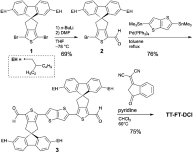
The synthetic routes to TT–FT–DCI, TT–T–DCI, TT–T(bo)–DCI, and TT–T(eh)–DCI are shown in Scheme 1. As the starting material for TT–FT–DCI, dibromo FT compound (1) was prepared by our reported method.55 Compound 1 was mono-lithiated and reacted with N,N-dimethylformamide (DMF) to synthesize formylated compound 2. The Migita–Kosugi–Stille coupling between 2 and 2,5-bistrimethylstannylthieno[3,2-b]thiophene afforded 3. Finally, Knoevenagel condensation of 2 with DCI afforded TT–FT–DCI. The other acceptors of TT–T–DCI, TT–T(bo)–DCI, and TT–T(eh)–DCI were synthesized in the same manner (Scheme S1†). As summarized in Table S1,† while TT–T(bo)–DCI and TT–T(eh)–DCI showed limited solubilities of less than 2 mg mL−1 in representative process solvents such as chloroform (CHCl3), chlorobenzene, and o-dichlorobenzene, TT–T–DCI showed improved solubility in CHCl3 and o-dichlorobenzene. In contrast, TT–FT–DCI possesses a high solubility of >10 mg mL−1 owing to the combination of spiro-substituted fluorene units with branched 2-ethylhexyl chains. Therefore, in the following section, we use TT–FT–DCI and TT–T–DCI.First, we investigated the thermal properties of TT–FT–DCI and TT–T–DCI (Fig. S2†). Thermogravimetric analysis (TGA) under a N2 atmosphere showed no significant weight loss of either compound up to 300 °C, and 5% weight loss was observed at 328 and 332 °C for TT–FT–DCI and TT–T–DCI, respectively. This result indicates that these molecules are thermally stable and can be used in OSCs. As a result of sweeping up to 300 °C by differential scanning calorimetry analysis, melting and crystallization peaks were observed at 265 °C and 200 °C for TT–T–DCI. In contrast, TT–FT–DCI showed a gentle heat capacity shift with no clear peak. These results indicate that TT–T–DCI possesses crystalline nature, whereas TT–FT–DCI is expected to form amorphous state in the solid state.
2.2. Computational studies
To understand the influence of the FT unit on the rigidity of the π-conjugated skeleton, potential energies against dihedral angles were estimated for TT–FT(m) and TT–T(m) using density functional theory (DFT) calculations at B3LYP with 6-31G(d,p) basis set. Note that we replaced all alkyl groups with methyl groups to reduce the computational load (denoted as FT(m) and T(m) for clarity). From each potential energies, probabilities (P) against dihedral angles were plotted based on the equation P = exp(−Ei/kBT), where Ei, kB, and T are the energy of the i metastable state, Boltzmann constant, and temperature, respectively (Fig. 2a).60 Whereas TT–T(m) exhibited a broad probability between θ = 180° and 140°, TT–FT(m) has a relatively narrow distribution. This result indicates that the introduction of the FT unit contributes to suppressing the dynamic fluctuation.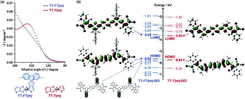 | ||
| Fig. 2 (a) Probabilities against dihedral angles for TT–FT(m) and TT–T(m), and (b) molecular orbitals and their energy levels for TT–FT(m)–DCI and TT–T(m)–DCI. | ||
We also optimized the model structures of TT–FT(m)–DCI and TT–T(m)-DCI (Fig. S3†). These results suggest that TT–FT–DCI and TT–T–DCI possess a planar π-conjugated skeleton. The spiro-flanked fluorene units in TT–FT(m)–DCI were aligned perpendicular to the main π-conjugated skeleton. This steric configuration is expected to suppress the π–π stacking interactions in the thin-film. The lowest unoccupied molecular orbitals (LUMOs) and highest occupied molecular orbitals (HOMOs) of TT–FT(m)–DCI and TT–T(m)–DCI are illustrated in Fig. 2b. These frontier orbitals are distributed throughout the π-conjugated main chain. Although no coefficients were present in the fluorene unit of TT–FT(m)–DCI, the molecular orbitals of the fluorene units were found at HOMO − 1 (−5.70 eV) and HOMO − 2 (−5.71 eV). The estimated LUMO and HOMO energy levels of these compounds were almost identical, and compounds with LUMO energy levels of approximately −3.5 eV were expected to function as acceptor materials.9,10,13,14
2.3. Electrochemical and photophysical properties
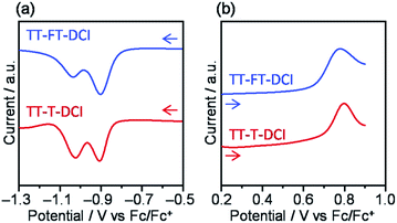
To investigate the electrochemical properties of TT–FT–DCI and TT–T–DCI, cyclic voltammetry (CV) and differential pulse voltammetry (DPV) were performed in dichloromethane (CH2Cl2) containing 0.1 M tetrabutylammonium hexafluorophosphate (TBAPF6) as the supporting electrolyte, and the potentials were calibrated using a ferrocene/ferrocenium (Fc/Fc+) redox couple as an internal standard. The voltammograms are shown in Fig. 3 and S4,† and the electrochemical data extracted from DPV are summarized in Table 1. Reversible oxidation and irreversible reduction waves were observed for both compounds in the CV measurements (Fig. S4†). From the oxidation peak in DPVs in Fig. 3b, the HOMO energy levels (EHOMO) of TT–FT–DCI and TT–T–DCI were experimentally determined to be −5.71 and −5.75 eV, respectively.61,62 Based on the first reduction peaks, the LUMO energy levels (ELUMO) of TT–FT–DCI and TT–T–DCI were determined to be the identical value of −3.89 eV. The similar energy levels of TT–FT–DCI and TT–T–DCI indicate that the electronic perturbation of the spiro-substituted fluorene units against the π-conjugated framework is limited.| Compound | E red /V | E ox /V | E LUMO /eV | E HOMO /eV | λ max (sol.)c/nm | ε/L mol−1 cm−1 | λ max (film)/nm | E A /eV | I p /eV |
|---|---|---|---|---|---|---|---|---|---|
| a Determined by DPV. b Approximation from DPV for the Fc/Fc+ level is −4.8 eV vs. vacuum. c In CHCl3. d Determined by LEIPS. e Determined by PYS. | |||||||||
| TT–FT–DCI | −0.91 | 0.91 | −3.89 | −5.71 | 680 | 1.24 × 10⁵ | 653 | 3.78 | 5.81 |
| TT–T–DCI | −0.91 | 0.95 | −3.89 | −5.75 | 617 | 0.67 × 10⁵ | 739 | 3.78 | 5.85 |
The electron affinity (EA) and ionization potential (Ip) of the thin films were determined using low-energy inverse photoemission spectroscopy (LEIPS) and photoelectron yield spectroscopy (PYS) (Fig. S5†). The EA value was found to be 3.78 eV below the vacuum level for both compounds. The Ip values were found to be 5.81 eV for TT–FT–DCI and 5.85 eV for TT–T–DCI. These estimated energy levels indicated that TT–FT–DCI and TT–T–DCI can function as acceptors when combined with low-bandgap donor polymers in OSCs.9,10,13,14
The photophysical properties of TT–FT–DCI and TT–T–DCI were investigated using UV-vis absorption spectroscopy in a dilute CHCl3 solution. As shown in Fig. 4a, while one absorption band with vibrational structure was observed for TT–FT–DCI, TT–T–DCI exhibited a broad structureless absorption band. Irrespective of the same π-conjugated framework, the maximum absorption wavelength (λmax) of TT–FT–DCI at 680 nm was red-shifted by 63 nm compared to that of TT–T–DCI (617 nm). Furthermore, the full width at half-maximum (FWHM) of the absorption band of TT–FT–DCI (110 nm; 2600 cm−1) is narrower than that of TT–T–DCI (146 nm; 4000 cm−1), and the molar absorption coefficient (ε) of TT–FT–DCI is 1.8 times larger than that of TT–FT–DCI. The absorption spectra of TT–FT–DCI and TT–T–DCI showed no concentration dependence in the range of 0.2–50 μM (Fig. S6†), indicating that the observed difference between TT–FT–DCI and TT–T–DCI was not caused by intermolecular interactions. We also measured temperature-dependent absorption spectra. As shown in Fig. 4c and d, with decreasing temperature, the λmax of TT–FT–DCI and TT–T–DCI red-shifted with increasing ε values. These results imply that the thermodynamic conformational probability has a significant influence on the photophysical properties. To support this hypothesis, time-dependent (TD) DFT calculations at the B3LYP/6-31G(d,p) level were performed for TT–FT(m)–DCI and TT–T(m)–DCI. In the case of the optimized planar structures, the corresponding transitions from HOMO to LUMO were predicted to be 710 nm with an oscillator strength (f) of 2.54 for TT–FT(m)–DCI and 700 nm with f = 2.69 for TT–T(m)–DCI. Since these calculated results did not reproduce the experimental phenomena well, we performed dihedral-dependent TD-DFT calculations to investigate the influence of planarity on the absorption spectra. As summarized in Fig. S7,† with a decreasing dihedral angle between thiophene and thienothiophene units from 180° to 90°, the calculated λmax values were blue-shifted and the f values became smaller for both TT–FT(m)–DCI and TT–T(m)–DCI. Because the trend in the distorted structure agrees well with the absorption spectra of TT–T–DCI, we considered that TT–T–DCI can exhibit conformational flexibility in solutions. In contrast, the presence of cyclopentene-annelated thiophene in TT–FT–DCI is effective in forming a rigid structure, leading to a narrow probability of conformation and a relatively high ε value in solution. Fig. 4b shows the emission spectra of TT–FT–DCI and TT–T–DCI in a CHCl3 solution. The maximum emission wavelengths were 728 nm for TT–FT–DCI and 719 nm for TT–T–DCI. In contrast to the absorption spectra, there was no significant difference in the maximum emission wavelengths of TT–T–DCI and TT–T–DCI. This result indicates that these molecules possess similar electronic structures in the excited states. From the λmax and emission maxima, the Stokes shifts were calculated to be 970 cm−1 for TT–FT–DCI and 2300 cm−1 for TT–T–DCI. The relatively small Stokes shift of TT–FT–DCI supports improved molecular planarity.
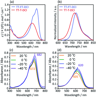 | ||
| Fig. 4 UV-vis absorption spectra (a) and emission spectra (b) in CHCl3 solutions. Temperature-dependent UV-vis absorption spectra for (c) TT–FT–DCI and (d) TT–T–DCI in dichloromethane. | ||
Compared to the solution state, the TT–T–DCI film showed an apparent red shift of approximately 120 nm. This result was rationalized by the appearance of strong intermolecular interactions in the solid state (Fig. 5).63,64 In contrast, a large overlap between the solution and thin-film spectra was observed for TT–FT–DCI, indicating that the presence of the FT unit disturbed the intermolecular interactions.53 Owing to changes in the vibronic structures, the λmax of TT–FT–DCI in the film was blue-shifted in comparison to that in the solution. The optical energy gaps (Eoptg) of TT–FT–DCI and TT–T–DCI in the film state were calculated from the onset wavelength of the absorption spectra. Eoptg was 1.58 eV for both the compounds.
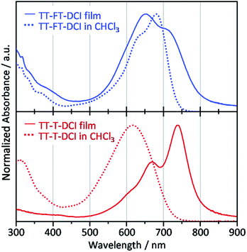 | ||
| Fig. 5 UV-vis absorption spectra of films (solid lines) and in CHCl3 solutions (dotted lines) for TT–FT–DCI and TT–T–DCI. | ||
X-ray diffraction (XRD) measurements were performed to investigate the molecular arrangement of the thin films (Fig. S8†). The pristine TT–FT–DCI thin-film showed very weak diffraction at θ = 4–5° (d = ∼2 nm) in the in-plane direction. This d-spacing roughly corresponded to the length of the molecular long-axis. Therefore, we considered that TT–FT–DCI mainly formed amorphous films with concomitant small crystal structures with face-on alignment. In contrast, for the TT–T–DCI thin-film, a clear diffraction peak was observed at 4.8° (d = 1.8 nm) in the out-of-plane direction and 24.8° (d = 0.36 nm) in the in-plane direction. These d-spacings correspond to the long axis length and the general π–π stacking distance. Therefore, TT–T–DCI forms a crystalline structure with an edge-on alignment in the thin-film state. The observed bathochromic shift in the TT–T–DCI thin-film is in good agreement with the XRD results. We also considered that the narrow FWHM of the absorption band of TT–T–DCI in the film is due to the formation of an ordered structure.
2.4. OSC characteristics
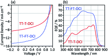
The photovoltaic characteristics of TT–FT–DCI and TT–T–DCI as new acceptors were investigated using an inverted configuration of ITO/ZnO/PBDB-T65 (CAS Registry No. 1415929-80-4):acceptor/MoO3/Ag.66 The details of the device fabrication condition are provided in the ESI.† The chemical structure of PBDB-T is presented in Fig. S1.† The active layers were optimized by screening the donor and acceptor ratios, process solvents, additives, concentrations, and rotational speeds (Tables S2 and S3†). The current density (J)–voltage (V) characteristics of the OSCs under AM 1.5 G solar irradiation (100 mW cm−2) and the corresponding external quantum efficiency (EQE) spectra are shown in Fig. 6. The results for operational stability of these devices are shown in Fig. S9.† The representative device parameters of short-circuit current (JSC), open-circuit voltage (VOC), and fill factor (FF) are summarized in Table 2. The best PCEs of TT–FT–DCI and TT–T–DCI were 7.13 and 3.41%, respectively. Compared with those of the PBDB-T:TT–T–DCI device, the JSC and FF of the PBDB-T:TT–FT–DCI-based device were improved. This result indicates that TT–FT–DCI has advantages for carrier dynamics from exciton formation to charge extraction in OSCs, which will be discussed in the following sections. The EQE measurements showed that the PBDB-T:TT–FT–DCI device recorded a maximum value (EQEmax) of 68% at 580 nm, whereas the PBDB-T:TT–T–DCI device showed an EQEmax of 41% at 730 nm. Fig. S10† shows the absorption spectra of the active layers formed on the quartz plates. Because the EQE responses around 500–650 and 600–750 nm were mainly attributable to PBDB-T and TT–FT–DCI, respectively, both the donor and acceptor contributed to the photocurrent generation. The difference in the VOC values of PBDB-T:TT–FT–DCI and PBDB-T:TT–T–DCI devices was 0.02 V. From the onset wavelengths of the absorption spectra of the active layers, the Eoptg(D:A) values of the PBDB-T:TT–FT–DCI and PBDB-T:TT–T–DCI blend films were estimated to be 1.57 eV (792 nm) and 1.59 eV (778 nm), respectively. From the equation Eloss = Eoptg(D:A) − eVOC,67,68 the energy loss (Eloss) was calculated to be 0.68 eV for both the OSCs.| Acceptor | J SC /mA cm−2 | V OC /V | FFa/% | PCEa,b/% | R sh /Ω cm2 | R s /Ω cm2 | EQEmax/% | μ e /cm2 V−1 s−1 | μ h /cm2 V−1 s−1 |
|---|---|---|---|---|---|---|---|---|---|
| a ITO/ZnO/PBDB-T:acceptor/MoO3/Ag. b The average and standard deviation of 5 devices are provided in parentheses, see the ESI for details. c Shunt resistance (Rsh) and series resistance (Rs) were estimated from J–V curves on Fig. S6b. d ITO/ZnO/PBDB-T:acceptor/Ca/Al. e ITO/PEDOT:PSS/PBDB-T:acceptor/MoO3/Ag. | |||||||||
| TT–FT–DCI | 14.30 | 0.89 | 56 | 7.13 (7.02 ± 0.11) | 7.7 × 10⁴ | 6 | 68 | 1.3 × 10⁻⁶ | 7.7 × 10⁻⁶ |
| TT–T–DCI | 8.22 | 0.91 | 46 | 3.41 (3.08 ± 0.20) | 5.5 × 10² | 35 | 41 | 9.4 × 10⁻⁸ | 3.3 × 10⁻⁶ |
The surface morphologies of the PBDB-T:TT–FT–DCI and PBDB-T:TT–T–DCI blend films were investigated by atomic force microscopy (AFM). As illustrated in Fig. S11,† the PBDB-T:TT–FT–DCI films showed a more distinct grain structure with a mean square roughness (Rrms) of 2.1 nm, whereas the PBDB-T:TT–T–DCI films formed a smooth surface with an Rrms of 0.68 nm. The active layers were also investigated using transmission electron microscopy (TEM). As shown in Fig. S12,† the films did not show any significant macroscopic ordered structures, indicating that both PBDB-T:TT–FT–DCI and PBDB-T:TT–T–DCI blend films form homogeneous active layers.
To investigate the crystallinity and molecular arrangement of the PBDB-T:TT–FT–DCI and PBDB-T:TT–T–DCI films, XRD measurements were performed. As shown in Fig. S8,† the crystallinity of the blend films resembled that of the acceptor pristine films. The PBDB-T:TT–T–DCI film exhibited distinct diffraction based on TT–T–DCI, whereas the PBDB-T:TT–FT–DCI film showed a very weak diffraction peak at θ = 4.4° in the out-of-plane direction attributed to TT–FT–DCI.
To estimate the macroscopic hole and electron mobilities, the space-charge limited current (SCLC) of blended films were investigated using ITO/PEDOT:PSS/PBDB-T:acceptor/MoO3/Ag for hole-only devices and ITO/ZnO/PBDB-T:acceptor/Ca/Al for electron-only devices.69–71 The J–V and J–V2d−3 plots are shown in Fig. S13,† and the estimated hole mobilities (μh) and electron mobilities (μe) are listed in Table 2. The hole transport attributed to PBDB-T exhibited the same order of magnitude of μh in both blend films. In contrast, the μe value of the PBDB-T:TT–FT–DCI films was two orders of magnitude higher than that of the PBDB-T:TT–T–DCI films. This result indicates that TT–FT–DCI has an aptitude for electron transport in OSCs, and the balanced μh and μe of the PBDB-T:TT–FT–DCI blend film is considered to contribute to the higher FF of the OSCs.72–75 The edge-on orientation of TT–T–DCI in the PBDB-T:TT–T–DCI film, which was observed in the XRD results (Fig. S8†), is disadvantageous for the electron transport.
2.5. Time-resolved UV-vis and infrared absorption spectroscopy
Picosecond transient absorption (TA) measurements were performed to understand the photoinduced responses of TT–FT–DCI and TT–T–DCI. As shown in Fig. S14a and b,† broad absorption was observed at approximately 990 nm for both neat TT–FT–DCI and TT–T–DCI films by 730 nm laser pulse irradiation. This absorption was assigned to the singlet excited state (S1), and the lifetime of S1 of TT–FT–DCI was longer than that of the TT–T–DCI films, as shown in Fig. 7a.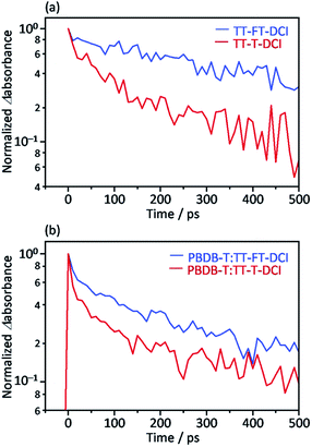 | ||
| Fig. 7 Time profile of the transient absorption at 990 nm for (a) TT–FT–DCI and TT–T–DCI neat films and (b) PBDB-T:TT–FT–DCI and PBDB-T:TT–T–DCI blend films. | ||
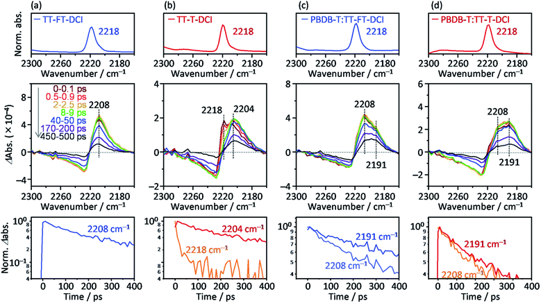
To further investigate the photoexcited dynamics of TT–FT–DCI and TT–T–DCI, changes in the vibrational frequency of the CN group were observed using time-resolved IR (TR-IR) absorption spectroscopy. This method is useful for observing the changes in the electronic and molecular structures induced by photoirradiation because the vibrational frequencies are very sensitive to the changes in the charge densities around the chemical bonds.76,77 When TT–FT–DCI was photoexcited, the TR-IR spectra of CN exhibited a bipolar shape with negative and positive peaks at 2225 and 2208 cm−1, respectively (Fig. 8a and S16a†). This spectral change indicates that the vibrational frequency of CN observed at 2218 cm−1, on the top of Fig. 8a, was red-shifted by photoexcitation, indicating that the density of electron around CN is increased. A similar red-shift was observed for TT–T–DCI, but an additional peak appeared at 2218 cm−1 (Fig. 8b). The peak intensities at 2218 cm−1 and 2204 cm−1 decreased remarkably and increased immediately after excitation. This is in contrast to that of TT–FT–DCI, which is almost constant within a few ps. The decrease of 2218 cm−1 TA and the increase of 2204 cm−1 TA of TT–T–DCI shown in Fig. S16b† are well correlated, indicating that some electronic and/or structural changes occurred within a few picoseconds. A possible reason for the few-picosecond TR-IR signal is the conformational relaxation of the TT–T–DCI molecular structure. One of the reasons for this conformational change is the torsional motion of the π-conjugated skeleton from a nonplanar to planar configuration. The skeleton of TT–T–DCI is expected to be more flexible than that of TT–FT–DCI; therefore, it is likely to deviate slightly from the planar structure in the film. After photoexcitation, the structure of TT–T–DCI can relax to a more planar conformation within picoseconds.78,79 In contrast, such conformational changes would be limited for TT–FT–DCI because it has a more rigid structure than TT–T–DCI.
The same TA measurements were performed for the blend films of TT–FT–DCI and TT–T–DCI with PBDB-T. In this experiment, only the acceptor molecules (TT–FT–DCI or TT–T–DCI) were excited using 730 nm laser pulses. As shown in Fig. S15a and b,† a broad absorption was also observed at approximately 990 nm for both PBDB-T:TT–FT–DCI and PBDB-T:TT–T–DCI films, which are assigned to S1 and/or the radical anion of TT–FT–DCI or TT–T–DCI. As in the case of the blend films, the lifetime of the charged species in PBDB-T:TT–FT–DCI was longer than that in PBDB-T:TT–T–DCI (Fig. 7b).
To further understand the electronic re-distribution processes in PBDB-T:TT–FT–DCI and PBDB-T:TT–T–DCI, the frequency shift of CN was observed using TR-IR spectroscopy. In the case of PBDB-T:TT–FT–DCI (Fig. 8c), two positive peaks appeared at approximately 2208 and 2191 cm−1. The former was also observed in the neat TT–FT–DCI film (Fig. 8a), but the latter was absent in the neat TT–FT–DCI film. This result shows that the electron density around the CN of TT–FT–DCI was further increased in the presence of PBDB-T, indicating hole transfer from TT–FT–DCI to PBDB-T after exciton diffusion to the donor/acceptor interfaces. It is noted that the decay of the peak intensity at 2208 cm−1 (time constant τ = 386 ± 14 ps) was remarkably faster than that at 2191 cm−1 (τ = 705 ± 27 ps, bottom of Fig. 8c). This result indicates that the lifetime of holes located in PBDB-T is longer than that in TT–FT–DCI owing to hole transfer from TT–FT–DCI to PBDB-T and/or recombination of electrons and holes in the TT–FT–DCI domain.
In the case of PBDB-T:TT–T–DCI, two positive peaks appeared at 2208 and 2191 cm−1, similar to the case of PBDB-T:TT–FT–DCI. However, the peak intensity at 2208 cm−1 is much smaller than that at 2191 cm−1 even at 0–0.1 ps (Fig. 8d). Furthermore, the decay rate of the peak intensity at 2208 cm−1 (τ = 304 ± 14 ps) was similar to that at 2191 cm−1 (τ = 341 ± 9 ps, bottom of Fig. 8d), which is in contrast to the case of PBDB-T:TT–FT–DCI. This indicates that the hole transfer from TT–T–DCI to PBDB-T is completed in hundreds of picoseconds region. These results show that the hole transfer from TT–T–DCI to PBDB-T occurs more rapidly and effectively than in PBDB-T:TT–FT–DCI because the TT–T–DCI domain is closely packed with a crystalline nature in contrast to the TT–FT–DCI domain with an amorphous nature. However, the band intensity of 2191 cm−1 in PBDB-T:TT–FT–DCI decayed remarkably slower than that in PBDB-T:TT–T–DCI (Fig. S17†), whereas the 2208 cm−1 band intensity decayed rapidly, indicating that the hole transfer proceeded from TT–FT–DCI via extensive exciton diffusion during the long survival time (705 ps from 2208 cm−1 decay of Fig. 8c) of the exciton and that the lifetime of holes in PBDB-T:TT–FT–DCI was longer than that of holes PBDB-T:TT–T–DCI. This result could be accounted for by considering the electron mobility (Table 2): the electron mobility of TT–FT–DCI is larger than that of TT–T–DCI. Hence, the electrons in TT–FT–DCI can easily move away from the holes, resulting in the suppression of recombination. These slower deactivation processes in TT–FT–DCI are responsible for the superior solar cell performance compared to that of TT–T–DCI.
2.6. Time-resolved microwave conductivity
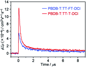
To investigate the lifetimes of free carriers in PBDB-T:TT–FT–DCI and PBDB-T:TT–T–DCI blend films, FP-TRMC measurements were performed.80 As shown in Fig. 9, the transient photoconductivity (ϕΣμ) of the PBDB-T:TT–FT–DCI blend displays the maximum ϕΣμmax of 5.5 × 10⁻⁴ cm2 V−1 s−1, where ϕ and Σμ represent the charge carrier generation yield and the sum of the hole and electron mobilities, respectively.80 The ϕΣμmax of the PBDB-T:TT–T–DCI blend was found to be 1.2 × 10⁻³ cm2 V−1 s−1. Therefore, it was suggested that the PBDB-T:TT–T–DCI blend film shows a higher local mobility associated with a more substantial self-assembling nature than PBDB-T:TT–FT–DCI, as evident from the UV-vis absorption spectra in Fig. 5 and the XRD data in Fig. S8.†Based on TA, TR-IR, and FP-TRMC measurements, it is indicated that TT–FT–DCI possesses a longer lifetime for the S1 and charge-transfer (CT) state, as well as for the charge-separation (CS) state, than TT–T–DCI. The longer lifetimes of these transient species are expected to facilitate photocarrier generation in OSCs, which rationalizes the high JSC and shunt resistance (Rsh) of the PBDB-T:TT–FT–DCI based OSCs.
2.7. Time-resolved electron paramagnetic resonance
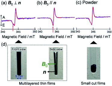
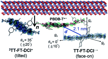
To visualize conformations of the CS state, we mapped (Fig. 11a) the electron spin polarization (i.e. the transverse magnetization at a field position indicated by the arrow in Fig. 10a) to all the field directions obtained from the fittings of the TREPR spectra.84 A grazing-incidence wide-angle X-ray scattering study88 of the ITO/ZnO/PBDB-T:ITIC blend film reported that PBDB-T polymers took on the face-on structures toward the out-of-substate direction, while the ITIC molecules tended to be disordered by the blend when 0.5% DIO additive was present. Based on this, it is very likely that the face-on character of TT–FT–DCI−˙ in the CS state reflects the π–π stackings between TT–FT–DCI and PBDB-T (Fig. S8f†), which directly interacts with the ZnO surface, as shown by the aromatic molecule underneath the ZnO surface in Fig. 11b. From the above discussion with θn = 0° ± 10°, one can obtain a geometric model of the CS state, as shown in Fig. 11b, when the principal axis systems are considered as shown in Fig. 11c and d. Notably, a direct face-on interaction between the TT–FT–DCI aromatic plane and the ZnO surface is unlikely at θn = 0° because of the steric hindrance by the spiro-fluorene groups substituted in the acceptor. This is consistent with the tilted conformation of the triplet exciton shown in Fig. S21d and S22c.† Additionally, the face-on situations of the donor interacting with the cathode (Fig. 11b) may hinder the electron injection through insulating LUMOs of the donors, resulting in the trapped CS states following the initial singlet exciton migration toward the ZnO surface regions and subsequent charge separations, as was characterized to be the trapped triplet excitons in the pristine films of the disordered environments (Fig. S18†). The present trap characteristics of the CS state were supported by observations of Rabi oscillation81 at a microwave power of 2.5 mW (Fig. S23†).
Thus, it is conceived that the present CS states are generated as a result of long-range exciton diffusions within the nanosecond survival time (705 ps from the 2208 cm−1 decay of Fig. 8c) in the vicinity of the ZnO surface, causing the trap characteristics via the dielectric response from ZnO, which possesses a higher dielectric constant89 (εs ≈ 8) than organic semiconductors. Based on the exciton diffusion coefficients (Dex = 10−2 cm2 s−1) of the related NFA films,90 the exciton diffusion length was estimated to be  when τ = 1 ns is substituted as the present survival time of the exciton. This coincides well with the width (120 nm) of the photoactive layer, suggesting that ultimate distant charge separations dominantly occur around the ZnO surface area following long-range exciton-diffusion. This is also consistent with a previous report that showed that the molar ratio of NFA molecules is larger at the ZnO surface than that of the donor.88
In addition to the spin-polarized CS states, second-lived trapped radical species were also observed using steady-state EPR spectroscopy under field modulations during 532 nm laser irradiations at 80 K (Fig. S24 and S25†). However, the E/A polarized SCRP spectrum in Fig. 11b is absent at room temperature (Fig. S26†), indicating that the shorter-lived SCRP was de-trapped and thus contributed to the photocurrent, because the distance between the charges was sufficiently long (r = 2.1 nm). More details on the trap characteristics and the effects of exciton diffusion are described in Fig. S25–S27.†
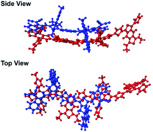
In our previous study, we showed that the face-on orientations of acceptors against the aromatic planes of donors at the interfaces are advantageous for charge separation.91,92 Therefore, to investigate the optimized stacking structure of PBDB-T and TT–FT–DCI, TT–FT(m)–DCI was placed on top of a model substructure of PBDB-T in a face-on conformation at a distance, and the structural optimization was performed by a DFT method with B3LYP-D3/6-31G(d,p) using Gaussian 16.93 As a result, the bimolecular model converged to a stacking geometry with the distance between π-conjugated planes approaching approximately 4.3 Å (Fig. 12). TD-DFT calculations were carried out to estimate the optical transitions of the PBDB-T:TT–FT(m)–DCI complex, which showed transitions attributed to the CT transition between 750 and 900 nm (Fig. S28†). These CT transitions shifted to longer wavelengths compared with the corresponding transitions from pristine PBDB-T and TT–FT(m)–DCI. These calculated results reproduced the experimental results well: the absorption spectrum of the PBDB-T:TT–FT–DCI blend film showed a broad absorption band around 750 nm (Fig. S10(a) (top)†), which is red-shifted compared to that of the pristine TT–FT–DCI film (700–730 nm) (Fig. S10a (bottom)†). We considered that this band is partially attributed to the transition from the PBDB-T:TT–FT–DCI complex. Thus, the electrons and holes can also be separated via the CT states in PBDB-T:TT–FT–DCI to generate the distant CS states.
The second-lived radical signals were also compared between the blend samples employing different acceptor molecules using steady-state EPR during 532 nm laser irradiations at 80 K (Fig. S31†). From the EPR intensities, the amount of accumulated charge was evaluated to be 2.6 times higher in the PBDB-T:TT–FT–DCI blend film than in PBDB-P:TT–T–DCI. Interestingly, this difference agrees well with the short-circuit current densities (JSC = 14.30 mA cm−2 in PBDB-T:TT–FT–DCI vs. JSC = 8.22 mA cm−2 in PBDB-T:TT–T–DCI) of the solar cells. Thus, it is concluded that the well-separated charges, including the transient CS states (Fig. 11b) at 80 K, can be de-trapped to contribute to the photocurrent densities for device performance at room temperature.
More importantly, the present locally ordered CS state conformation nearby the cathode is the highlight of the highly disordered morphology in view of whole photoactive layers employing the spiro-fluorene substitutions. Not only the homogeneous donor/acceptor miscibility for the efficient exciton migrations and subsequent charge generations as characterized by the long survival times in Fig. 8c, the local face-on conformation at the cathode side is a key to certainly inject the electrons for μe ≪ μh in Table 2 with preventions of the electron–hole recombination to conduct the superior PCE and VOC values. In this respect, the direct interaction between the tilted π-orbital of acceptor and the ZnO surface (Fig. 13) is a crucial gateway for efficient electron injection when the triplet exciton trapping is absent under solar-irradiation. This is consistent with the larger μe of the OSC employing the TT–FT–DCI than that of the OSC with the TT–T–DCI acceptor.
3 Conclusion
In summary, to investigate the effects of rigid and sterically bulky structures of non-fused NFAs on transient photon-to-current dynamics, a new electron-accepting π-conjugated molecule, TT–FT–DCI, was developed. Theoretical calculations and photophysical measurements indicated that the introduction of the FT unit was effective for the rigidification of the π-conjugated framework. The JSC and FF of the PBDB-T:TT–FT–DCI-based OSCs were significantly improved compared to those of PBDB-T:TT–T–DCI-based OSCs, achieving a maximum PCE of 7.13%. Time-resolved IR absorption spectroscopy of the pristine thin-films revealed that TT–FT–DCI exhibited smaller conformational relaxation than TT–T–DCI under photoexcitation conditions, which primarily originates from the rigid π-conjugated framework of TT–FT–DCI. Furthermore, TT–FT–DCI showed longer lifetimes of the excited and charge-separated states in the blend films than TT–T–DCI. For FP-TRMC measurements, a longer lifetime of free carriers was observed for the PBDB-T:TT–FT–DCI film. Time-resolved EPR measurements revealed that the CS state of PBDB-T:TT–FT–DCI adopted a face-on conformation near the ZnO electrode. This orientation is rationalized by the suppression of aggregation between the TT–FT–DCI molecules due to the presence of sterically bulky spiro-substituted fluorene units. We demonstrated that the rigid and sterically bulky structure of non-fused NFA has advantages in the dynamic process of photon-to-current conversion in the active layer of OSCs, which provides important insights into the material design for high-performance non-fused NFAs as well as deep understanding of solar cell operating mechanisms.Conflicts of interest
There are no conflicts to declare.Acknowledgements
This work was supported by JSPS KAKENHI (20H02814, 20K21224, 20H05841, 20KK0123, 19K15505, 20H04639, 20K15352, 21H05406, 20H05838, 19H00888, and 20K21174), CREST (J205101030), NEDO (21500248-0), and “Dynamic Alliance for Open Innovation Bridging Human, Environmental and Materials” from the Ministry of Education, Culture, Sports, Science and Technology, Japan. We are thankful to Nanotechnology Open Facilities, Osaka University (JPMXP09S21OS0010) for PYS measurements. We are also thankful to the Thermal & Electric Energy Technology Inc. Thanks are extended to the CAC, SANKEN, for assistance in obtaining elemental analyses and high-resolution mass spectra. Theoretical calculations for the dimer model were performed at Research Center for Computational Science in the Institute for Molecular Science (IMS) in Okazaki, Japan.Notes and references
- A. Polman, M. Knight, E. C. Garnett, B. Ehrler and W. C. Sinke, Science, 2016, 352, aad4424 CrossRef PubMed.
- C. Yan, S. Barlow, Z. Wang, H. Yan, A. K.-Y. Jen, S. R. Marder and X. Zhan, Nat. Rev. Mater., 2018, 3, 18003 CrossRef CAS.
- P. Cheng, G. Li, X. Zhan and Y. Yang, Nat. Photonics, 2018, 12, 131–142 CrossRef CAS.
- J. Zhang, H. S. Tan, X. Guo, A. Facchetti and H. Yan, Nat. Energy, 2018, 3, 720–731 CrossRef CAS.
- O. Inganäs, Adv. Mater., 2018, 30, 1800388 CrossRef PubMed.
- G. Yu, J. Gao, J. C. Hummelen, F. Wudl and A. J. Heeger, Science, 1995, 270, 1789–1791 CrossRef CAS.
- J. J. M. Halls, K. Pichler, R. H. Friend, S. C. Moratti and A. B. Holmes, Appl. Phys. Lett., 1996, 68, 3120–3122 CrossRef CAS.
- G. Zhang, J. Zhao, P. C. Y. Chow, K. Jiang, J. Zhang, Z. Zhu, J. Zhang, F. Huang and H. Yan, Chem. Rev., 2018, 118, 3447–3507 CrossRef CAS PubMed.
- A. Wadsworth, M. Moser, A. Marks, M. S. Little, N. Gasparini, C. J. Brabec, D. Baran and I. McCulloch, Chem. Soc. Rev., 2019, 48, 1596–1625 RSC.
- C. B. Nielsen, S. Holiday, H.-Y. Chen, S. J. Cryer and I. McCulloch, Acc. Chem. Res., 2015, 48, 2803–2812 CrossRef CAS PubMed.
- S. Chatterjee, S. Jinnai and Y. Ie, J. Mater. Chem. A, 2021, 9, 18857–18886 RSC.
- D. Luo, W. Jang, D. D. Babu, M. S. Kim, D. H. Wang and A. K. K. Kyaw, J. Mater. Chem. A, 2022, 10, 3255–3295 RSC.
- D. Li, X. Zhang, D. Liu and T. Wang, J. Mater. Chem. A, 2020, 8, 15607–15619 RSC.
- Q. Yue, W. Liu and X. Zhu, J. Am. Chem. Soc., 2020, 142, 11613–11628 CrossRef CAS PubMed.
- C. Xu, Z. Zhao, K. Yang, L. Niu, X. Ma, Z. Zhou, X. Zhang and F. Zhang, J. Mater. Chem. A, 2022, 10, 6291–6329 RSC.
- X. Wang, Q. Sun, J. Gao, J. Wang, C. Xu, X. Ma and F. Zhang, Energies, 2021, 14, 4200 CrossRef CAS.
- Y. Lin, J. Wang, Z. G. Zhang, H. Bai, Y. Li, D. Zhu and X. Zhan, Adv. Mater., 2015, 27, 1170–1174 CrossRef CAS PubMed.
- W. Zhao, D. Qian, S. Zhang, S. Li, O. Inganäs, F. Gao and J. Hou, Adv. Mater., 2016, 28, 4734–4739 CrossRef CAS PubMed.
- J. Yuan, Y. Zhang, L. Zhou, G. Zhang, H.-L. Yip, T.-K. Lau, X. Lu, C. Zhu, H. Peng, P. A. Johnson, M. Leclerc, Y. Cao, J. Ulanski, Y. Li and Y. Zou, Joule, 2019, 3, 1140–1151 CrossRef CAS.
- L. Zhan, S. Li, Y. Li, R. Sun, J. Min, Z. Bi, W. Ma, Z. Chen, G. Zhou, H. Zhu, M. Shi, L. Zuo and H. Chen, Joule, 2022, 6, 662–675 CrossRef CAS.
- Y. Cui, Y. Xu, H. Yao, P. Bi, L. Hong, J. Zhang, Y. Zu, T. Zhang, J. Qin, J. Ren, Z. Chen, C. He, X. Hao, Z. Wei and J. Hou, Adv. Mater., 2021, 33, 2102420 CrossRef CAS PubMed.
- A. Karki, J. Vollbrecht, A. J. Gillett, S. S. Xiao, Y. Yang, Z. Peng, N. Schopp, A. L. Dixon, S. Yoon, M. Schrock, H. Ade, G. N. M. Reddy, R. H. Friend and T.-Q. Nguyen, Energy Environ. Sci., 2020, 13, 3679–3692 RSC.
- J. Sun, Z. Zhang, X. Yin, J. Zhou, L. Yang, R. Geng, F. Zhang, R. Zhu, J. Yu and W. Tang, J. Mater. Chem. A, 2018, 6, 2549–2554 RSC.
- L.-M. Wang, Q. Li, S. Liu, Z. Cao, Y.-P. Cai, X. Jiao, H. Lai, W. Xie, X. Zhan and T. Zhu, ACS Appl. Mater. Interfaces, 2020, 12, 24165–24173 CrossRef CAS PubMed.
- B. Kan, J. Zhang, F. Liu, X. Wan, C. Li, X. Ke, Y. Wang, H. Feng, Y. Zhang, G. Long, R. H. Friend, A. B. Bakulin and Y. Chen, Adv. Mater., 2018, 30, 1704904 CrossRef PubMed.
- M. T. Sajjad, A. Ruseckas, L. K. Jagadamma, Y. Zhang and I. D. W. Samuel, J. Mater. Chem. A, 2020, 8, 15687–15694 RSC.
- Y. Zhong, M. Causa, G. J. Moore, P. Krauspe, B. Xiao, F. Günther, J. Kublitski, R. Shivhare, J. Benduhn, E. BarOr, S. Mukherjee, K. M. Yallum, J. Rehault, S. C. B. Mannsfeld, D. Neher, L. J. Richter, D. M. DeLongchamp, F. Ortmann, K. Vandewal, E. Zhou and N. Banerji, Nat. Commun., 2020, 11, 833 CrossRef CAS PubMed.
- W. Li, M. Chen, J. Cai, E. L. K. Spooner, H. Zhang, R. S. Gurney, D. Liu, Z. Xiao, D. G. Lidzey, L. Ding and T. Wang, Joule, 2019, 3, 819–833 CrossRef CAS.
- G. Han, Y. Guo, X. Song, Y. Wang and Y. Yi, J. Mater. Chem. C, 2017, 5, 4852–4857 RSC.
- S. M. Swick, T. Gebraad, L. Jones, B. Fu, T. J. Aldrich, K. L. Kohlstedt, G. C. Schatz, A. Facchetti and T. J. Marks, ChemPhysChem, 2019, 20, 2608–2626 CrossRef CAS PubMed.
- X. Zhang, H. Wang, D. Li, M. Chen, Y. Mao, B. Du, Y. Zhuang, W. Tan, W. Huang, Y. Zhao, D. Liu and T. Wang, Macromolecules, 2020, 53, 3747–3755 CrossRef CAS.
- X. Song, P. Sun, D. Sun, Y. Xu, Y. Liu and W. Zhu, Nano Energy, 2022, 91, 106678 CrossRef CAS.
- X. Song, K. Zhang, R. Guo, K. Sun, Z. Zhou, S. Huang, L. Huber, M. Reus, J. Zhou, M. Schwartzkopf, S. V. Roth, W. Liu, Y. Liu, W. Zhu and P. Müller-Buschbaum, Adv. Mater., 2022, 34, 2200907 CrossRef CAS PubMed.
- J. Kalowekamo and E. Baker, Sol. Energy, 2009, 83, 1224–1231 CrossRef CAS.
- J. Min, Y. N. Luponosov, C. Cui, B. Kan, H. Chen, X. Wan, Y. Chen, S. A. Ponomarenko, Y. Li and C. J. Brabec, Adv. Energy Mater., 2017, 7, 1700465 CrossRef.
- W. Yang, W. Wang, Y. Wang, R. Sun, J. Guo, H. Li, M. Shi, J. Guo, Y. Wu, T. Wang, G. Lu, C. J. Brabec, Y. Li and J. Min, Joule, 2021, 5, 1209–1230 CrossRef.
- Y. Gao, M. Cui, S. Qu, H. Zhao, Z. Shen, F. Tan, Y. Dong, C. Qin, Z. Wang, W. Zhang, Z. Wang and Y. Lei, Small, 2022, 18, 2104623 CrossRef CAS PubMed.
- L. Ma, S. Zhang, J. Wang, Y. Xu and J. Hou, Chem. Commun., 2020, 56, 14337–14352 RSC.
- S. Li, L. Zhang, F. Liu, J. Ren, M. Shi, C.-Z. Li, T. P. Russell and H. Chen, Adv. Mater., 2018, 30, 1705208 CrossRef PubMed.
- S. Feng, M. Li, N. Tang, X. Wang, H. Huang, G. Ran, Y. Liu, Z. Xie, W. Zhang and Z. Bo, ACS Appl. Mater. Interfaces, 2020, 12, 4638–4648 CrossRef CAS PubMed.
- S. Chatterjee, Y. Ie, T. Seo, T. Moriyama, G.-J. A. H. Wetzelaer, P. W. M. Blom and Y. Aso, NPG Asia Mater., 2018, 10, 1016–1028 CrossRef CAS.
- T. Duan, M. Babics, A. Seitkhan, Y. Firdaus, R.-Z. Liang, F. Cruciani, S. Liu, S. Lopatin and P. M. Beaujuge, J. Mater. Chem. A, 2018, 6, 9368–9372 RSC.
- K. J. Thorley and I. McCulloch, J. Mater. Chem. C, 2018, 6, 12413–12421 RSC.
- T.-J. Wen, Z. X. Liu, Z. Chen, J. D. Zhou, Z. Q. Shen, Y. Q. Xiao, X. H. Lu, Z. Q. Xie, H. M. Zhu, C.-Z. Li and H. Z. Chen, Angew. Chem., Int. Ed., 2021, 60, 12964–12970 CrossRef CAS PubMed.
- X. Wang, X. Cui, H. Lu, Y.-N. Chen, Y. Liu, Y. Zhou, C. Zhang, J. Song, C. Li, Z. Zhang and Z. Bo, Org. Electron., 2021, 89, 106029 CrossRef CAS.
- Z.-P. Yu, Z.-X. Liu, F.-X. Chen, R. Qin, T.-K. Lau, J.-L. Yin, X. Kong, X. Liu, M. Shi, C.-Z. Li and H. Chen, Nat. Commun., 2019, 10, 2152 CrossRef PubMed.
- X. Li, Z. Xu, X. Guo, Q. Fan, M. Zhang and Y. Li, Org. Electron., 2018, 58, 133–138 CrossRef CAS.
- D. Luo, X. Lai, N. Zheng, C. Duan, Z. Wang, K. Wang and A. K. K. Kyaw, Chem. Eng. J., 2021, 420, 129768 CrossRef CAS.
- Y.-N. Chen, M. Li, Y. Wang, J. Wang, M. Zhang, Y. Zhou, J. Yang, Y. Liu, F. Liu, Z. Tang, Q. Bao and Z. Bo, Angew. Chem., Int. Ed., 2020, 59, 22714–22720 CrossRef CAS PubMed.
- L. Ma, S. Zhang, J. Zhu, J. Wang, J. Ren, J. Zhang and J. Hou, Nat. Commun., 2021, 12, 5093 CrossRef CAS PubMed.
- M. Yang, W. Wei, X. Zhou, Z. Wang and C. Duan, Energy Mater., 2021, 1, 100008 Search PubMed.
- Y. Ie, Y. Okamoto, T. Inoue, S. Tone, T. Seo, Y. Honda, S. Tanaka, S. K. Lee, T. Ohto, R. Yamada, H. Tada and Y. Aso, J. Phys. Chem. Lett., 2019, 10, 3197–3204 CrossRef CAS PubMed.
- Y. Ie, M. Endou, S. K. Lee, R. Yamada, H. Tada and Y. Aso, Angew. Chem., Int. Ed., 2011, 50, 11980–11984 CrossRef CAS PubMed.
- Y. Ie, Y. Okamoto, T. Inoue, T. Seo, T. Ohto, R. Yamada, H. Tada and Y. Aso, J. Am. Chem. Soc., 2021, 143, 599–603 CrossRef CAS PubMed.
- Y. Ie, Y. Okamoto, S. Tone and Y. Aso, Chem.–Eur. J., 2015, 21, 16688–16695 CrossRef CAS PubMed.
- T. Ohto, T. Inoue, H. Stewart, Y. Numai, Y. Aso, Y. Ie, R. Yamada and H. Tada, J. Phys. Chem. Lett., 2019, 10, 5292–5296 CrossRef CAS PubMed.
- H. Bürckstümmer, N. M. Kronenberg, M. Gsänger, M. Stolte, K. Meerholz and F. Würthner, J. Mater. Chem., 2010, 20, 240–243 RSC.
- H. Bai, Y. Wang, P. Cheng, J. Wang, Y. Wu, J. Hou and X. Zhan, J. Mater. Chem. A, 2015, 3, 1910–1914 RSC.
- Suman and S. P. Singh, J. Mater. Chem. A, 2019, 7, 22701–22729 RSC.
- Y. Che and D. F. Perepichka, Angew. Chem., Int. Ed., 2021, 60, 1364–1373 CrossRef CAS PubMed.
- A. J. Bard and L. R. Faulkner, Electrochemical Methods-Fundamentals and Applications, Wiley, New York, 1984 Search PubMed.
- J. Pommerehne, H. Vestweber, W. Guss, R. F. Mahrt, H. Bässler, M. Porsch and J. Daub, Adv. Mater., 1995, 7, 551 CrossRef CAS.
- H. Yamagata and F. C. Spano, J. Chem. Phys., 2012, 136, 184901 CrossRef CAS PubMed.
- S. T. Turner, P. Pingel, R. Steyrleuthner, E. J. W. Crossland, S. Ludwigs and D. Neher, Adv. Funct. Mater., 2011, 21, 4640–4652 CrossRef CAS.
- D. Qian, L. Ye, M. Zhang, Y. Liang, L. Li, Y. Huang, X. Guo, S. Zhang, Z. Tan and J. Hou, Macromolecules, 2012, 45, 9611–9617 CrossRef CAS.
- W. Zhao, S. Li, H. Yao, S. Zhang, Y. Zhang, B. Yang and J. Hou, J. Am. Chem. Soc., 2017, 139, 7148–7151 CrossRef CAS PubMed.
- C. Xu, K. Jin, Z. Xiao, Z. Zhao, X. Ma, X. Wang, J. Li, W. Xu, S. Zhang, L. Ding and F. Zhang, Adv. Funct. Mater., 2021, 31, 2107934 CrossRef CAS.
- W. Xu, X. Ma, J. H. Son, S. Y. Jeong, L. Niu, C. Xu, S. Zhang, Z. Zhou, J. Gao, H. Y. Woo, J. Zhang, J. Wang and F. Zhang, Small, 2022, 18, 2104215 CrossRef CAS PubMed.
- G. G. Malliaras, J. R. Salem, P. J. Brock and C. Scott, Phys. Rev. B: Condens. Matter Mater. Phys., 1998, 58, 13411 CrossRef.
- C. Goh, R. J. Kline, M. D. McGehee, E. N. Kadnikova and J. M. J. Fréchet, Appl. Phys. Lett., 2005, 86, 122110 CrossRef.
- S. D. Dimitrov and J. R. Durrant, Chem. Mater., 2014, 26, 616 CrossRef CAS.
- C. M. Proctor, J. A. Love and T.-Q. Nguyen, Adv. Mater., 2014, 26, 5957–5961 CrossRef CAS PubMed.
- J. A. Bartelt, D. Lam, T. M. Burke, S. M. Sweetnam and M. D. McGehee, Adv. Energy Mater., 2015, 5, 1500577 CrossRef.
- S. Li, L. Ye, W. Zhao, X. Liu, J. Zhu, H. Ade and J. Hou, Adv. Mater., 2017, 29, 1704051 CrossRef PubMed.
- K. Chong, X. Xu, H. Meng, J. Xue, L. Yu, W. Ma and Q. Peng, Adv. Mater., 2022, 34, 2109516 CrossRef CAS PubMed.
- T. Mani, D. C. Grills, M. D. Newton and J. R. Miller, J. Am. Chem. Soc., 2015, 137, 10979–10991 CrossRef CAS PubMed.
- Y. Song, X. Liu, Y. Li, H. H. Nguyen, R. Duan, K. J. Kubarych, S. R. Forrest and J. P. Ogilvie, J. Phys. Chem. Lett., 2021, 12, 3410–3416 CrossRef CAS PubMed.
- X. Tan, T. L. Gustafson, C. Lefumeux, G. Burdzinski, G. Buntinx and O. Poizat, J. Phys. Chem. A, 2002, 106, 3593–3598 CrossRef CAS.
- K. P. Ghiggino, A. J. Tilley, B. Robotham and J. M. White, Faraday Discuss., 2015, 177, 111–119 RSC.
- A. Saeki, Polym. J., 2020, 52, 1307–1321 CrossRef CAS PubMed.
- Y. Kobori, T. Ako, S. Oyama, T. Tachikawa and K. Marumoto, J. Phys. Chem. C, 2019, 123, 13472–13481 CrossRef CAS.
- P. J. Hore, D. A. Hunter, C. D. McKie and A. J. Hoff, Chem. Phys. Lett., 1987, 137, 495–500 CrossRef CAS.
- G. L. Closs, M. D. E. Forbes and J. R. Norris, J. Phys. Chem., 1987, 91, 3592–3599 CrossRef CAS.
- M. Hasegawa, H. Nagashima, R. Minobe, T. Tachikawa, H. Mino and Y. Kobori, J. Phys. Chem. Lett., 2017, 8, 1179–1184 CrossRef CAS PubMed.
- M. Van Landeghem, W. Maes, E. Goovaerts and S. Van Doorslaer, J. Magn. Reson., 2018, 288, 1–10 CrossRef CAS PubMed.
- O. Gonen and H. Levanon, J. Phys. Chem., 1984, 88, 4223–4228 CrossRef CAS.
- T. Biskup, M. Sommer, S. Rein, D. L. Meyer, M. Kohlstadt, U. Wurfel and S. Weber, Angew. Chem., Int. Ed., 2015, 54, 7707–7710 CrossRef CAS PubMed.
- L.-M. Wang, Q. Li, S. Liu, Z. Cao, Y.-P. Cai, X. Jiao, H. Lai, W. Xie, X. Zhan and T. Zhu, ACS Appl. Mater. Interfaces, 2020, 12, 24165–24173 CrossRef CAS PubMed.
- R. J. Collins and D. A. Kleinman, J. Phys. Chem. Solids, 1959, 11, 190–194 CrossRef CAS.
- Y. Firdaus, V. M. L. Corre, S. Karuthedath, W. Liu, A. Markina, W. Huang, S. Chattopadhyay, M. M. Nahid, M. I. Nugraha, Y. Lin, A. Seitkhan, A. Basu, W. Zhang, I. McCulloch, H. Ade, J. Labram, F. Laquai, D. Andrienko, L. J. A. Koster and T. D. Anthopoulos, Nat. Commun., 2020, 11, 5220 CrossRef CAS PubMed.
- S. Jinnai, Y. Ie, M. Karakawa, T. Aernouts, Y. Nakajima, S. Mori and Y. Aso, Chem. Mater., 2016, 28, 1705–1713 CrossRef CAS.
- S. Jinnai, Y. Ie, Y. Kashimoto, H. Yoshida, M. Karakawa and Y. Aso, J. Mater. Chem. A, 2017, 5, 3932–3938 RSC.
- M. J. Frisch, et al., Gaussian 16 A. 01, Gaussian, Inc., Wallingford CT, 2009 Search PubMed.
- Y. Kobori and T. Miura, J. Phys. Chem. Lett., 2015, 6, 113–123 CrossRef CAS PubMed.
- T. Miura, M. Aikawa and Y. Kobori, J. Phys. Chem. Lett., 2014, 5, 30–35 CrossRef CAS PubMed.
- Y. Kobori, R. Noji and S. Tsuganezawa, J. Phys. Chem. C, 2013, 117, 1589–1599 CrossRef CAS.
Footnote |
| † Electronic supplementary information (ESI) available: Detailed synthetic procedures and characterization data for new compounds and additional experimental results. See https://doi.org/10.1039/d2ta02604j |
| This journal is © The Royal Society of Chemistry 2022 |


