 Open Access Article
Creative Commons Attribution 3.0 Unported Licence
Metal–organic framework structures of fused hexagonal motifs with cuprophilic interactions of a triangular Cu(I)3(pyrazolate-benzoate) metallo-linker†
Saskia
Menzel‡
 a,
Tobias
Heinen‡
a,
Ishtvan
Boldog
a,
Tobias
Heinen‡
a,
Ishtvan
Boldog
 *a,
Thi Hai Yen
Beglau
a,
Shanghua
Xing
ab,
Alex
Spieß
a,
Dennis
Woschko
 a and
Christoph
Janiak
 *a
*a
aInstitut für Anorganische Chemie und Strukturchemie, Heinrich Heine-Universität Düsseldorf, Universitätsstraße 1, Düsseldorf 40225, Germany. E-mail: boldogi@hhu.de; janiak@uni-duesseldorf.de
bHoffmann Institute of Advanced Materials, Shenzhen Polytechnic, 7098 Liuxian Blvd, Nanshan District, Shenzhen 518055, China
First published on 25th April 2022
Abstract
The reaction of the N,O-heteroditopic bifunctional ligand 4-(3,5-dimethyl-1H-pyrazol-4-yl)benzoic acid (H2mpba) with Cu(NO3)2·2.5H2O and Zn(NO3)2·4H2O or Zn(CH3COO)2·2H2O in N,N-dimethylformamide (DMF) results in concomitant formation of three bimetallic metal–organic frameworks (MOFs) with open structures, [Me2NH2][Zn4{CuI3(mpba)3}3(Me2NH)-(DMF)2] (1), [Zn6{CuI3(mpba)3}4(DMF)5] (2) and [Zn3{CuI3(mpba)3}2(DMF)3(H2O)][Zn4(μ4-O){CuI3(mpba)3}2(H2O)4] (3). Compounds 1 and 3 are isolable in phase pure form under specified conditions. The HSAB hard/soft metal–ligand selectivity (CuI–N and Zn–O) allows the structure assembly based on the 3-c trigonal planar {CuI3(pz)3} moiety (pz = pyrazolate) and various 4-6-c {Znx(O)y(COO)z} (x = 2–4, y = 0–1, z = 4–6) secondary building units to be realized neatly. The in situ formed softer CuI atoms coordinate with the softer pyrazolate nitrogen donor atoms of the pyrazolate–carboxylate ligand, leaving the carboxylate groups for linking to the Zn atoms. The triangular and trinuclear {CuI3(mpba)3}3− metallacycle acts as a tricarboxylate linker between the Znx nodes and can be regarded as an expanded version of the benzene-1,3,5-tricaboxylate linker. In all structures the {CuI3(pz)3} moiety is stacked in infinite columns by cuprophilic interactions suggesting the initial formation of the Cu3(mpba) metallo-ligand. The variable geometry Zn clusters, which are paddle-wheel type, pyramidal and trigonal-prismatic, adapt to the stacked orientation of the carboxylate groups from the {CuI3(mpba)3}3− metallacycles. As a result, the formed structures could be viewed as derived from stacked hexagonal honeycomb hcb nets, via ‘fusion’ of alternating stacked nodes. The resulting nets retain the geometric similarity to the hcb net when viewed along the normal direction to the stack, and the individual topologies represent open structures. The minority phase 2 features 2D layers with a ‘dual-strand’ hcb net, {43}2{43·612}. 1 consists of parallel polycatenation, 2D + 2D → 3D, of triple layers with a point symbol of {4·62}2{42·66·82}{63}{65·8}, while 3 presents a pair of interpenetrated 3D + 3D {4·6·8}{42·65·85·103} nets as a rare case of hetero-interpenetration. The binodal net in 3 is a rare sqc-3,6-Fdd2-2 type sqc-subnet and the first example in a MOF. In spite of the interpenetration, 3 retains significant porosity and could be activated to demonstrate permanent porosity, thereby classifiable as a MOF with an Ar-based BET surface area of 762 m2 g−1 (87 K) and a CO2 adsorption capacity at 1 bar of 78 cm3 g−1 (273 K) and 46 cm3 g−1 (293 K). The structure organization similarities of 1–3, stipulated by cuprophilic interactions, could have a general importance for linear heteroditopic ligands analogous to H2mpba offering a ‘fused-hcb’ design approach towards open structures.
Introduction
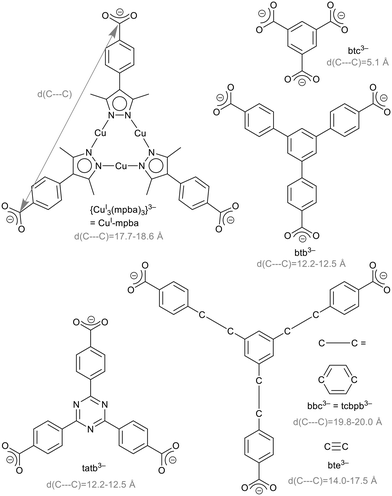
The research area of metal–organic frameworks (MOFs) has reached a high degree of maturity with highly varied topologies1,2 and wide-spread properties.3–5 MOFs are built from metal clusters, also called secondary building units (SBUs), and bridging organic ligands, so-called linkers.6,7 In the rational design of MOFs, the isoreticularity principle foresees the use of linkers with different sizes but the same geometry to obtain MOFs of the same topology. Benzene-1,3,5-tricarboxylate (btc3−, Scheme 1) is an important linker, used for example in the prototypical MOF Cu-btc (HKUST-1),8 Zn-btc9–12 or Cd-btc.10 Extended versions of this linker are 4,4′,4′′-benzene-1,3,5-triyl-tribenzoate, btb3−, 4,4′,4′′-(benzene-1,3,5-triyl-tris(benzene-4,1-diyl))tribenzoate, bbc3− = 1,3,5-tris(4′-carboxy[1,1′-biphenyl]-4-yl-)benzene, tcbpb3−, 4,4′,4′′-(benzene-1,3,5-triyl-tris(ethyne-2,1-diyl))tribenzoate, bte3−,4,4′,4′′-s-triazine-2,4,6-triyl-tribenzoate, tatb3− (Scheme 1) and 4,4′,4′′-(triazine-2,4,6-triyl-tris(benzene-4,1-diyl))tribenzoate (tapb3−) as used in the MOFs listed in Table 1.| Liganda | Examplec |
|---|---|
| a See Scheme 1. b Not shown in Scheme 1, but tapb is like bbc with a triazine instead of a benzene core. c Other abbreviations used: (bib = 1,4-bis(2-methylimidazol-1-yl)butane), NMP = N-methyl pyrrolidone, pdp = 2-(4,6-di(pyridine-2-yl)pyridine-2-yl)pyridine, tbib = 1,3,5-tri(1H-benzo[d]-imidazol-1-yl)benzene, tpt = 2,4,6-tris-(4-pyridyl)-1,3,5-triazine, p/m-bib = para/meta-bis((1H-imidazole-1-yl)methyl)benzene. | |
| btc3− | Cu-btc (HKUST-1),8 Zn-btc,9–12 Cd-btc10 |
| btb3− | MOF-14(Cu),17 MOF-143(Cu),18 DUT-9(Ni),19 MOF-177(Zn),13,14,20 [Cd3(btb)2(bib)(DMF)3],21 {[Ba3(btb)2(NMP)2(H2O)2]·2NMP·H2O},22 {[Co(Hbtb)(pdp)]·H2O},23 [Cd2(tbib)(btb)(H2O)2]X,24 {[Eu(btb)(H2O)3]·1.5DMA·5H2O}n (MHT-1),25 MUV-12,26 FJU-120 (ref. 27) |
| bbc3− = tcbpb3− | {[Zn4(OH)2(H2O)2(py)2(tcbpb)2]·DMF·py·3H2O},28 {[Zn8(OH)4(tcbpb)4]·2DMF·2EtOH·3H2O},28 Al-tcbpb,29 MOF-399(Cu),18 DUT-40(Zn),15 DUT-41(Zn),15 MOF-200(Zn),20 MOF-1005(Zr)30 |
| bte3− | MOF-180(Zn),20 MOF-1004(Zr)30 |
| tatb3− | [Ln2(tatb)2(DMSO)6] (Ln = La, Ce, Pr, MOF-388Sm, Eu),31 {[Ln2(tatb)2(DMSO)5(CH3OH)]·DMF·DMSO·2H2O} (Ln = Nd, Gd, Tb),31 [Cu2(tatb)2(H2O)3],32 PCN-9(Co),33 MIL-142(Sc)-tatb,34 [Co4(SO4)3(F)3(tpt)2(tatb)],35 [Fe(tatb)(p/m-bib)]36 |
| tapb3−b | MOF-388(Cu)18 |
The Zn-MOFs with the trigonal linkers Zn-btc,9–12 MOF-177 (btb3−),13,14 MOF-180 (bte3−)13 and MOF-200 (bbc3−)13 are isoreticular to each other, and so is DUT-40 (bbc3−) to DUT-41 (bbc3−).15
The limits of isoreticular expansion as well as the influence of the ligand's nature in this regard is an interesting conceptual question. Our interest is focused on the triangular tri-copper metallo-linker, {CuI3(mpba)3}3− (in short CuI-mpba), which can be seen as belonging to the btc-type linker family (Scheme 1). Practically the only MOF-type open framework compound featuring the CuI-mpba unit is PCN-91, reported by Zhou and co-workers, which is a CuII coordination polymer with a Pt3O4 underlying net.16 CuI-mpba is constructed from three CuI atoms, which linearly coordinate pyrazolate nitrogen donor atoms of three deprotonated bifunctional 4-(3,5-dimethyl-1H-pyrazol-4-yl)benzoic acid (H2mpba) ligands. In comparison to other trigonal linkers, the CuI-mpba metallo-linker is quite large with an edge length d(C---C) of 17.7–18.6 Å (Scheme 1). Its size is comparable to one of the largest typically used trigonal linkers bbc3− (= tcbpb3−) (d(C---C) = 19.8–20.0 Å, Scheme 1). Furthermore, CuI-mpba is not rigid and planar but somewhat flexible and distorted (vide infra), similar to bbc3− and bte3−.13,30 The arms of the latter two ligands deflect from the plane of the central benzene ring by up to 10° (Fig. S44, ESI†). If the benzoate groups bend all out of the central ring plane to one side, a bowl-shaped linker is formed.15,30 The linker bte3− appears to be the most flexible example as the ethinyl-benzoate groups do not only bend out of the central ring plane but also deviate from a 120° angle between them (Fig. S44†).30 The flexibility of the CuI-mpba ligand stems from the flexibility of the coordination-bonded core, with pyrazolate–phenyl non-planarity due to steric repulsion between the methyl groups of pyrazolate and the phenyl ortho-hydrogen atoms, which also endows the ligand branches with a limited rotational degree of freedom.
The trinuclear CuI-pyrazolate arrangement is well known in {CuI3(pz)3} clusters (pz = 3,5-R-pyrazolate, where R is a group with intermediary steric volume, typically Me, sometimes CF3 or Ph, and only rarely H. In the latter case the {CuI2(pz)2} cyclic motif is rather realized). The more widespread, structurally close form of that cluster is {Cu3(μ3-OH)(pz)3}n–, based on Cu(I/II) or Cu(II) only (importantly, the pz = 3,5-H-pyrazolate ligand is very typical for the μ3-OH-centered clusters, unlike for the Cu(I)-only cluster).37 As special feature of copper(I), the {CuI3(pz)3} clusters are very prone to associate via intermolecular cuprophilic interactions, which could affect the course of self-assembly of potential MOFs.38,39 There is a fortunate opportunity for the synthesis of potential mixed-metal MII–IV/CuI pyrazolate–carboxylate coordination polymers staring from CuII as a precursor in N,N-dimethylformamide (DMF) and similar amide solvents. The latter are favorable for the crystallization of both carboxylate and pyrazolate coordination polymers, while elevated temperatures (80–120 °C) ensure partial or complete reduction of CuII to CuI.40
The doubly deprotonated bifunctional pyrazolate–carboxylate ligand mpba2−, constituting {CuI3(mpba)3}3−, has already been used in the synthesis of a few reported coordination-bonded frameworks with other coordination bonded clusters, namely ZnII,41–43 CoII![[thin space (1/6-em)]](https://www.rsc.org/images/entities/char_2009.gif) 43 or CuII.16,44 It is also worth mentioning the reported, mostly 2D, structures of the partially deprotonated pyrazole-carboxylate ligand Hmbpa− with Co(II), Ni(II), Zn(II), Cu(II), Cd(II)45 and the mixed-metal 1D bimetallic coordination polymer {[(Ti3O)(iPro)8][Hmpba]2[Cu2I2]0.5} (with iPro = isopropoxide).46 In the case of the mixed-valent CuI/II framework compound of PCN-91 (ref. 16) and the 1D TiIV–CuI coordination polymer, the harder carboxylate group combines with the HSAB-harder metal ions CuII and TiIV and the HSAB-softer pyrazolate or pyrazole donor is coordinated by CuI (according to the HSAB principle).47 The hard/soft selectivity of the O,N heteroditopic mbpa2− ligand offers a potentially productive approach towards mixed metal coordination polymers, based on the in situ synthesized {CuI3(mpba)3}3− cluster.
43 or CuII.16,44 It is also worth mentioning the reported, mostly 2D, structures of the partially deprotonated pyrazole-carboxylate ligand Hmbpa− with Co(II), Ni(II), Zn(II), Cu(II), Cd(II)45 and the mixed-metal 1D bimetallic coordination polymer {[(Ti3O)(iPro)8][Hmpba]2[Cu2I2]0.5} (with iPro = isopropoxide).46 In the case of the mixed-valent CuI/II framework compound of PCN-91 (ref. 16) and the 1D TiIV–CuI coordination polymer, the harder carboxylate group combines with the HSAB-harder metal ions CuII and TiIV and the HSAB-softer pyrazolate or pyrazole donor is coordinated by CuI (according to the HSAB principle).47 The hard/soft selectivity of the O,N heteroditopic mbpa2− ligand offers a potentially productive approach towards mixed metal coordination polymers, based on the in situ synthesized {CuI3(mpba)3}3− cluster.
Carboxylate coordination polymers also featuring the {CuI3(pz)3} cluster are rare. According to the CSD search, there are five compounds of this type, with three important MOF representatives, namely the mentioned PCN-91,16 FDM-4 (ref. 48) and FMD-8.49 The two other compounds are the CFA-13 MOF50 with an extended {CuI3(pz)3} cluster in the form of CuI3(3,5-CF3-pyrazolate)4, and the [CuII{CuI3(Hmpba)(mpba)2}] 1D coordination polymer51 reported by us. The FDM-4,5,6,7,8 series of Zn/Cu mixed-metal coordination polymers with surface areas up to 3728 m2 g−1, based on the fully deprotonated short 4-carboxypyrazole ligand as a sole organic ligand, or together with the 1,4-benzenedicarboxylate or 2,6-naphthalenedicarboxylate ligand, is particularly interesting. The series features reversible redox transformation between the {CuI3(pz)3} and {CuI, II3(OH)(pz)3} cluster without compromising the integrity of the structure (as some of the structures are reported only for the oxidized cluster, the CSD search does not cover the CuI-only variants in all cases). As mentioned above, 3,5-H-pyrazoles frequently constitute the {Cu3(OH)(pz)3} clusters, but they are less frequent in geometrically well-formed {CuI3(pz)3} clusters. The FDM-4-8 series demonstrate that in some cases both possibilities could be realized, resulting in highly porous robust structures, which substantiate the interest in mixed-metal and mixed-ligand complexes for longer ligands like mpba2−, whose potential is proven by the known PCN-91 material.
The CuI-mpba metallo-linker has not been used in the construction of isoreticular Zn-MOF structures (as well as any other bimetallic MOFs) and in the current contribution we explore this possibility. The bifunctional ligand precursor 4-(3,5-dimethyl-1H-pyrazol-4-yl)benzoic acid (H2mpba) was reacted with copper(II) nitrate in DMF in the presence of zinc(II) salts and, if necessary, a modulator (HBF4) aiming for Zn frameworks with the metallo-linker, akin to those with the btc, btb, bte or bbc linker (cf.Table 1). The importance of the HSAB selectivity regarding the mixed valent CuI/CuII metals and the N,O-heteroditopic ligand is explicitly discussed for PCN-91.16 The use of CuI/ZnII in this work could be viewed as a continuation of that principle aiming for the utilization of zinc (oxo)carboxylate species as secondary building units.
Results and discussion
The solvothermal reaction between copper(II) nitrate, zinc(II) nitrate and H2mba in N,N-dimethylformamide (DMF) at 80–90 °C for several days resulted in the formation of the bimetallic networks [Me2NH2][Zn4{CuI3(mpba)3}3(Me2NH)(DMF)2] (1), [Zn6{CuI3(mpba)3}4(DMF)5] (2) and [Zn7{CuI3(mpba)3}4(O)(H2O)5(DMF)3] (3). The synthesis conditions had to be carefully adjusted with regard to time, temperature, Cu![[thin space (1/6-em)]](https://www.rsc.org/images/entities/char_2009.gif) :
:![[thin space (1/6-em)]](https://www.rsc.org/images/entities/char_2009.gif) Zn stoichiometry and the amount of HBF4 modulator, as otherwise mixtures of 1, 2 and 3 also form (Table S1, Scheme S1, ESI†).
Zn stoichiometry and the amount of HBF4 modulator, as otherwise mixtures of 1, 2 and 3 also form (Table S1, Scheme S1, ESI†).
MOF examples in the literature with Cu(I)3(pyrazolate–carboxylate) motifs include PCN-91,16 FDM-4-8,48,49 CFA-13 (ref. 50) and [CuII{CuI3(Hmpba)(mpba)2}].51 The syntheses were all performed using Cu(II) as a precursor and in N,N-dimethylformamide (DMF) or similar amide solvents. DMF is favorable for the crystallization of both carboxylate and pyrazolate coordination polymers, while elevated temperatures (80–120 °C) in amide solvents ensure partial or complete reduction of Cu(II) to Cu(I).52
The {CuI3(pz)3} SBU of PCN-91 forms as a result of the in situ reduction of CuII (Cu(NO3)2·2.5H2O precursor) in DMA and two drops of pyridine at elevated temperature (120 °C) and prolonged time (24 h). In the work of Tu and co-workers, the short 4-pyrazolecarboxylate linker was used to synthesize bimetallic, redox active materials. By varying the Cu![[thin space (1/6-em)]](https://www.rsc.org/images/entities/char_2009.gif) :
:![[thin space (1/6-em)]](https://www.rsc.org/images/entities/char_2009.gif) Zn ratio and the solvent mixture (ratio of DMF and NMP or DMF and DMA (only used for FDM-5)) the materials FDM-4 and FDM-5 were synthesized under solvothermal conditions. By adding the organic ligand 1,4-benzene dicarboxylic acid the material FDM-6 was produced. FDM-8 and the substituted derivates NH2-FDM-8 and C4H4-FDM-8 were synthesized under solvothermal conditions by adding 1,4-benzenedicarboxylate acid, 2,6-naphalenedicarboxylate acid (for FDM-8) and 2-aminoterephthalic acid or 1,4-naphthalenedicarboxylate acid for NH2-FDM-8 and C4H4-FDM-8. In all FDM MOFs, the {CuI3(pz)3} moiety was obtained by in situ reduction from the Cu(II)-salt (Cu(NO3)2·3H2O) in DMF/NMP or DMF/DMA at elevated temperature (85 °C for FDM-4 and FDM-5, 100 °C for FDM-6, FDM-8 and NH2-FDM-8 and C4H4-FDM-8) and prolonged time (72 h for FDM-4 and FDM-5 and 16 h for FDM-6, FDM-8 and NH2-FDM-8).
Zn ratio and the solvent mixture (ratio of DMF and NMP or DMF and DMA (only used for FDM-5)) the materials FDM-4 and FDM-5 were synthesized under solvothermal conditions. By adding the organic ligand 1,4-benzene dicarboxylic acid the material FDM-6 was produced. FDM-8 and the substituted derivates NH2-FDM-8 and C4H4-FDM-8 were synthesized under solvothermal conditions by adding 1,4-benzenedicarboxylate acid, 2,6-naphalenedicarboxylate acid (for FDM-8) and 2-aminoterephthalic acid or 1,4-naphthalenedicarboxylate acid for NH2-FDM-8 and C4H4-FDM-8. In all FDM MOFs, the {CuI3(pz)3} moiety was obtained by in situ reduction from the Cu(II)-salt (Cu(NO3)2·3H2O) in DMF/NMP or DMF/DMA at elevated temperature (85 °C for FDM-4 and FDM-5, 100 °C for FDM-6, FDM-8 and NH2-FDM-8 and C4H4-FDM-8) and prolonged time (72 h for FDM-4 and FDM-5 and 16 h for FDM-6, FDM-8 and NH2-FDM-8).
Regarding the question of pKa, the carboxylic acid and pyrazole groups feature very different acidities (∼5 vs. 14), but this does not preclude the concomitant formation of complexes even for Zn(II). The HSAB hard–hard soft–soft matching between CuI and pyrazolate as well as ZnII and carboxylate makes the formation of the respective complexes highly predictable.
Compounds 1 and 3 could be obtained reproducibly as yellowish clear crystals (Fig. S1 and S2, ESI†) in phase pure form. Compound 2 was difficult to obtain in pure phase and in single crystal form, and it was only observed as an admixture of 1 and 3. The identity of the three compounds could by elucidated by single-crystal diffraction (see below). The experimental and simulated powder X-ray diffractograms were matched and the correspondence was checked by Le Bail fitting (Fig. S3, ESI;† compound 2, which could be obtained only in the form of a powder, is the least pure).
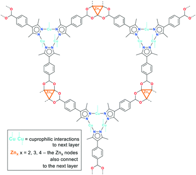
A common feature of the structures of 1–3 (Scheme 2) is the structural changeability of the Zn-SBU clusters, featuring nuclearities of 2–4 (distorted tetrahedral and pentagonal as well as trigonal-prismatic SBU-shapes) and frequent disorder. Such unconventional changeability contrasts the situation in PCN-91 with Cu(II), where the conventional {Cu2(O2C)4}-paddle-wheel motif is formed.16 Neither of 1–3 is isostructural to PCN-91, even if a paddle-wheel {Zn2(O2C)4}-SBU is possible.53 Instead, the structures of 1–3 have a common structure-guiding motif of columnar stacks, composed of CuI-mpba associated by cuprophilic interactions. The Zn-clusters appear to be flexible and adapt to the requirements imposed by the CuI-mpba stacks, which results in similarities in structure-organization dominated by the formation of hexagonal coordination-bonded rings within honeycomb hcb layers (Scheme 2; the summary of the work on the topological level is given below in Fig. 9, which follows the detailed description of the structures).
Crystal structure of 1
The formula of compound 1 was established as [Me2NH2][Zn4{CuI3(mpba)3}3(Me2NH)(DMF)2]. The formation of dimethylammonium [Me2NH2]+ from DMF and its presence as a counter-cation has been seen in zinc-MOFs with benzene-1,4-dicarboxylate,54 furan-2,5-dicarboxylate55 or 1,1′-biphenyl-3,3′,4,4′-tetracarboxylate.56 The asymmetric unit in 1 consists of three symmetry-independent {CuI3(mpba)3}3− units, each belonging to a different layer, which are associated via coordination with Zn-atoms (Fig. 1). The three layers give three-layer 2D sheets, referred to as ‘stacks’ (Fig. 2).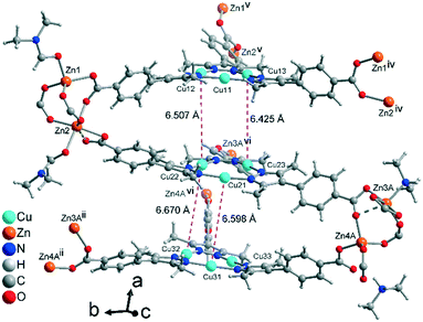 | ||
| Fig. 1 Extended asymmetric unit of 1 with the two located coordinating DMF solvent molecules, one dimethylamine solvent molecule and one dimethylammonium counter-cation (for further details on these amine/ammonium groups see Fig. S4, ESI†). Each {CuI3(mpba)3}3− unit belongs to a different layer. In view of the structure complexity, a ball-and-stick presentation is used and only the major contribution to the disorder of Zn3 and Zn4 is shown. The Zn3/4 disorder is described in more detail in the ESI.† The distances between the Cu atoms (pink dashed lines) correspond to twice the distances of typical cuprophilic Cu⋯Cu contacts, as the interlayer space is filled by a symmetry equivalent CuI-mbpa unit (the stack is shown in Fig. 3 and 4). Symmetry codes: (ii) x, y + 1, z; (iv) x, y − 1, z; (v) x, y − 1, z − 1; (vi) x, y, z − 1. | ||
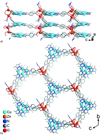 | ||
| Fig. 2 Wire-frame model of (a) side-view and (b) on-top view (along the b and a axis, respectively) of a section of a single 3-layer stack in 1. Only the major contribution to the disorder of Zn3 and Zn4 is depicted. See also the space-filling presentation in Fig. S5.† | ||
There are two dinuclear Zn-carboxylate clusters, which could be regarded as disrupted paddle-wheel arrangements. In the first cluster, the Zn1 atom has a tetrahedral {ZnO4+1} environment with an additional weaker Zn–O bond, while Zn2 has an octahedral environment, involving a chelating carboxylate, thereby not completing the usual paddle-wheel arrangement (both atoms coordinate one DMF molecule). In the second cluster, the Zn3 and Zn4 atoms are disordered over two different positions, A (81%) and B (19%), assuming alternating roles (Fig. S4, ESI† for the details of the disorder). In part A, the Zn3A atom coordinates a nitrogen atom from a dimethylamine solvent molecule in addition to five carboxylate oxygen atoms, two of which belong to a chelating carboxylate. This results in a strongly distorted octahedron as a coordination environment. The Zn4A atom is tetrahedrally coordinated by four oxygen atoms, two of which belong to monodentate carboxylates. In the absence of the second disordered component (Zn4B), the latter carboxylates are involved in hydrogen bonding with the charge compensating dimethylammonium cation, ensuring the coordination of five carboxylates per Zn2-cluster, instead of four.
The connection of the {CuI3(mpba)3}3− metallo-linkers with the Zn2-SBUs leads to hexagonal rings with the Cu3-centroid and Zn2-centroid as vertices and the mpba-ligands as edges (Fig. 2b). While {CuI3(mpba)3}3− is a three-connected node, the Zn1/Zn2 group acts as a four-connected node and the Zn3/Zn4 group as a five-connected node. Hence, each Zn1/Zn2 group belongs to the top and middle layer, and each Zn3/Zn4 group to the middle and bottom layer (according to the orientation in Fig. 1 and 2a).
The single 3-layer stack in 1 has a >6.4 Å separation between the metallo-linkers (Fig. 1, 2a, and S5a†) and possesses an open structure with hexagonal pores propagating along the a-direction (Fig. 2b and S5b†). A dense packing, however, minimizes the energy of a structure. Therefore, open frameworks often show phenomena of interpenetration, polycatenation or entanglement.57–62 In 1 the lower/upper half of a 3-layer stack polycatenates into the upper/lower halves of its neighbors (Fig. 3a and S6a†). At the same time the stacks are packed along the a-direction in a staggered fashion in an ABAB sequence, such that the {Cu3(pyrazolate)3}, i.e., {Cu3(pz)3}, parts of the metallo-linkers are stacked on top of each other (Fig. 3b and 4) and the Zn-SBUs fill most of the voids of the polycatenated stack (Fig. 3b and S6b, ESI†). Thereby, the available space in a single 3-layer stack is filled (compare Fig. 2b and 3b).
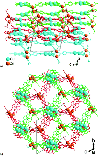 | ||
| Fig. 3 Wire-frame model of (a) side-view and (b) on-top view (along the b and a axis, respectively) of a section of three polycatenated 3-layer stacks in 1. The three stacks are differentiated by their green, red and cyan color. Hydrogen atoms are not shown for clarity. Only the major contribution to the disorder of Zn3 and Zn4 was used in the drawing. See also the space-filling presentation in Fig. S6, ESI.† | ||
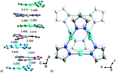 | ||
| Fig. 4 a) Stacking of the {CuI3(pz)3} moieties in 1 with CuI⋯CuI contacts (in cyan, in Å) between the polycatenated stacks which are differentiated by the same green, red and cyan color as in Fig. 3; the methyl groups are not shown for clarity. b) Alternation of the axial rotation of the {CuI3(pz)3} moieties. | ||
Two adjacent 3-layer stacks polycatenate in a parallel manner in a 2D + 2D motif. The infinite 2D + 2D polycatenation of upper/lower parts of neighboring 3-layer stacks along the perpendicular direction to the stack leads to a 3D network. Interpenetration which results in a higher dimensionality than the discrete network, that is, 2D → 3D, is termed polycatenation.60 A similar upper/lower part 2D + 2D polycatenation, giving an overall 3D network, is also frequently seen for (4,4)la double-layer sql nets.61
The polycatenation is invoked and stabilized through the inter-stack CuI⋯CuI contacts, with lengths between 3.099 Å and 3.643 Å (Fig. 4) which thus correspond to typical cuprophilic interactions.43,63–65 We note that these inter-stack CuI⋯CuI separations are in the same range as the CuI⋯CuI distances within the {Cu3(pz)3} clusters, which lie between 3.169 Å and 3.257 Å (Fig. S7, ESI†).
Crystal structure of 2
The asymmetric unit of 2 with the established formula of [Zn6{CuI3(mpba)3}4(DMF)5] (Fig. 5a) consists of four symmetry-independent {CuI3(mpba)3}3− metallo-linkers. They are pairwise stacked at short CuI⋯CuI distances of 3.413 Å and 3.786 Å and connected through two symmetry-independent {Zn3(O2C–)6(DMF)2–3} SBUs (Fig. 5b) to a two-dimensional 2-layer stack. The three Zn atoms in {Zn3(O2C–)6(DMF)2–3} form unsymmetrical hourglass-like trinuclear SBUs where the central Zn atoms (Zn2A, Zn5) rather have a square-pyramidal than bipyramidal environment (geometric index66τ = 0.42 and 0.32) coordinated by five carboxyl-O atoms from five different metallo-linkers (Fig. 5b).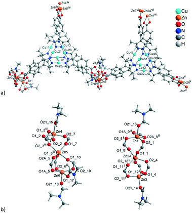 | ||
| Fig. 5 (a) Extended asymmetric unit of 2. The emphasis in this image is placed on the slightly shifted eclipsed position of the metallo-linkers. The inter-linker Cu⋯Cu contacts range from 3.57–3.79 Å (Fig. 6c). (b) The two trinuclear hourglass-like SBUs. Symmetry codes: (i) x − 1, y − 1, z + 1; (ii) x − 1, y, z + 1; (iii) x, y + 1, z; (iv) x, y − 1, z; (v) x + 1, y + 1, z − 1; (vi) x + 1, y, z − 1. Only the major contribution to the disordered carboxylates and Zn2 atoms is shown, and the Zn2 disorder is described in more details in Fig. S9, ESI.† | ||
The terminal Zn atoms possess either a tetrahedral (Zn3) or distorted square-pyramidal environment (Zn1, Zn4, Zn6 τ = 0.23, 0.08, 0.54), although Zn4 and Zn6 have additional long (>2.5 Å) contacts completing a distorted octahedral environment.66 The two Zn3-SBUs possess three crystallographically different ZnII ions. The coordination of the terminal Zn atoms Zn1, Zn3 and Zn4 is constructed from three carboxyl groups of metallo-linkers and one DMF molecule. For the five-coordinated atoms Zn1 and Zn4 one of the carboxyl groups is chelating and the DMF ligand is in the apical position. The five-coordinated Zn6 atom is bound to three monodentate carboxylates and two DMF ligands.
The 2D 2-layer stacks in 2 run parallel to the (1 0 1) plane (Fig. 6a). The combination of the {CuI3(mpba)3}3− metallo-linkers with the Zn3-SBUs leads again to a structure based on hexagonal rings, when the Cu3-centroids and the midpoints between two Zn atoms in the hourglass SBUs are considered as nodes of the underlying net and the mpba-ligands as edges (Fig. 6b). Two adjacent 2-layer stacks, related through a symmetry operation, become staggered along the a-direction, such that the Cu3(pyrazolate)3, i.e., the Cu3(pz)3, parts of the metallo-linkers are again stacked on top of each other (Fig. 6c), as was also seen in 1 (cf.Fig. 3). The terminal DMF ligands at the Zn3 hourglass-SBUs stick out of the stack and protrude into the adjacent stack (Fig. 6a).
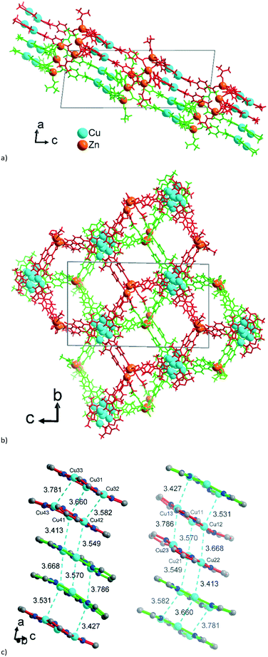 | ||
| Fig. 6 Wire-frame model of (a) side-view and (b) on-top view (along the b and a axis, respectively) of two adjacent 2-layer stacks in 2. The two stacks are differentiated by their green and red color. See also the space-filling presentation in Fig. S10, ESI.† (c) Stacking of the {CuI3(pz)3} moieties in 2 with CuI⋯CuI contacts (in cyan, distances in Å) between the layers. The inversion-symmetry relation of adjacent stacks renders the packing for the two symmetry-independent parts of the asymmetric unit of 2 (cf.Fig. 5a) equivalent. Thus, the red {CuI3(pz)3} units in the left column correspond to the green {CuI3(pz)3} units in the right column in Fig. 6c. | ||
Crystal structure of 3
The established formula of 3, [Zn3{CuI3(mpba)3}2(DMF)3(H2O)][Zn4(μ4-O){CuI3(mpba)3}2(H2O)4], reflects the presence of two symmetry-independent two-fold interpenetrating neutral networks, based on different Zn-SBUs. Network A = [Zn3{CuI3(mpba)3}2(DMF)3(H2O)] has the trinuclear Zn-SBU {Zn3(O2C–)6(DMF)3} (Fig. 7a). Network B = [Zn4(μ4-O){CuI3(mpba)3}2(H2O)4] has the tetranuclear {Zn4(μ4-O)(O2C–)6(H2O)4} Zn-SBU (Fig. 7b). While the trinuclear SBU could be well-refined, the interpretation of the second Zn-SBU is ambiguous. The conventional {Zn4(μ4-O)(O2C–)6} cluster is octahedral, while the demands imposed by the crystal structure of 3 prescribe a distorted trigonal-prismatic shape. The refined atoms, constituting the cluster, have large thermal displacement factors, allowing multiple interpretations. Based on the Zn![[thin space (1/6-em)]](https://www.rsc.org/images/entities/char_2009.gif) :
:![[thin space (1/6-em)]](https://www.rsc.org/images/entities/char_2009.gif) Cu ratio found by analytics and following general chemical logic, a complex, unresolved overlap of nearly regular {Zn4(μ4-O)(O2C–)6} clusters was assumed (Fig. S12, ESI†). An alternative, more straightforward interpretation is a pentanuclear {Zn5(μ4-O)(OH)2(O2C–)6} cluster with a minor disorder. Also, an admixture of Cu(I) such that the disordered {Zn4(μ4-O)} cluster might be {Zn4CuI(μ4-O)} could not be completely ruled out. Despite the different possible Zn4-SBU interpretations, the localization of the {CuI3(mpba)3} moieties and hence the connectivity in the framework is unambiguous.
Cu ratio found by analytics and following general chemical logic, a complex, unresolved overlap of nearly regular {Zn4(μ4-O)(O2C–)6} clusters was assumed (Fig. S12, ESI†). An alternative, more straightforward interpretation is a pentanuclear {Zn5(μ4-O)(OH)2(O2C–)6} cluster with a minor disorder. Also, an admixture of Cu(I) such that the disordered {Zn4(μ4-O)} cluster might be {Zn4CuI(μ4-O)} could not be completely ruled out. Despite the different possible Zn4-SBU interpretations, the localization of the {CuI3(mpba)3} moieties and hence the connectivity in the framework is unambiguous.
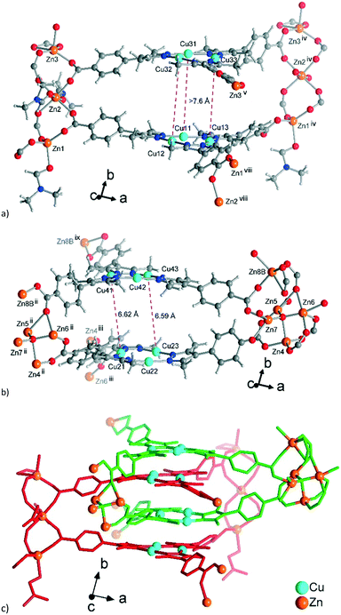 | ||
| Fig. 7 Extended asymmetric units in 3. (a) Network A, constituted by the trinuclear Zn-SBUs with branches ending with Zn atoms showing the connections. (b) Similar image for network B constituted by the tetranuclear Zn-SBUs. The Zn atoms in the middle of the images which point to the front (in a) and to the rear (in b) propagate the structure along the b-axis. The distances between the Cu atoms (pink dashed lines) correspond to twice the distances of typical cuprophilic Cu⋯Cu contacts. (c) The mode of interpenetration of network A, shown with red bonds and network B, shown with green bonds. In (b) the major disorder contributions to the Zn-atoms in the structure are shown. From the disorder, the Zn-SBU in (b) looks like a pentanuclear interpretation, yet the 80% occupancy gives a Zn4-SBU (see Fig. S11, ESI† for details). Symmetry codes: (ii) x − 1/2, y − 1/2, z; (iii) x − 1/2, −y − 3/2, z − 1/2; (iv) x + 1/2, y + 1/2, z; (v) x + 1/2, −y − 3/2, z + 1/2; (viii) x + 1/2, −y − 5/2, z + 1/2; (ix) x − 1/2, −y − 1/2, z − 1/2. | ||
Aside from the two different Zn SBUs, the asymmetric unit of each network consists of two symmetry-independent {CuI3(mpba)3}3− metallo-linkers, which are stacked in an eclipsed fashion at twice the distance, ∼6.5 Å, of optimal cuprophilic interaction between the {Cu3(pz)3} moieties, leaving room for an interpenetrating network, as in 1. The distance between the closest CuI atoms is over 6.5 Å (Fig. 7 and 8). Four of the six carboxylate groups of the two eclipsed {CuI3(mpba)3}3− metallo-ligands are pairwise ‘clamped’ by two of the Zn3 or Zn4 SBUs, similar to the arrangement in the structure of 2. The difference is that the remaining two carboxylate branches extend the network to the third dimension, perpendicular to the layers (along the b axis, Fig. 7). The connection of the {CuI3(mpba)3}3− metallo-linkers with the Zn-SBUs in 3 leads again to a structure dominated by hexagonal rings in both of the interpenetrating frameworks (Fig. 8). The inter-linker cuprophilic contacts43,63–65 condition the tight interpenetration with CuI⋯CuI distances between 2.933 Å and 3.661 Å (Fig. 8c) as in 1 (Fig. 4) and 2 (Fig. 6c).
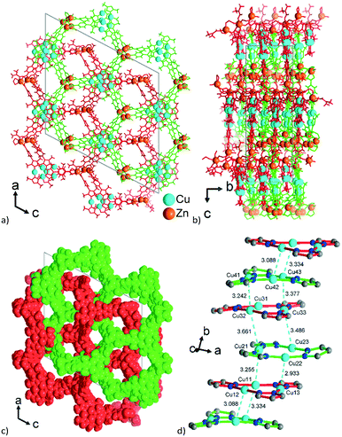 | ||
| Fig. 8 View along the hexagonal channels of the two interpenetrating 3D-frameworks in 3 as (a and b) wire-frame, two projections and (c) space-filling modes. Network A in red with the Zn3-SBU and network B in green with the Zn4-SBU (cf.Fig. 7). (d) Stacking of the {CuI3(pz)3} moieties in 3 with CuI⋯CuI contacts (in cyan, distances in Å) between the layers of the interpenetrating frameworks. | ||
Comparison of the structural organization and topology
Structures 1–3 demonstrate a distinct similarity regarding both the formation of hexagonal ring motifs (Fig. 3b, 6b, and Fig. 8a respectively; Fig. S14a, ESI†) and the columnar association of all present {Cu3(pz)3} moieties by CuI⋯CuI cuprophilic interactions (the high similarity of the columnar arrangements with staggered neighbor units is shown in Fig. S13†). The hexagonal rings are situated in an eclipsed way within a separate network/topology constituting open channels. The channel openings are partially occupied or blocked by polycatenated (1), just neighboring (2) or interpenetrated (3) networks which are arranged with respect to each other in a slipped or staggered mode similar to the ABAB layer sequence in graphite (Fig. 9).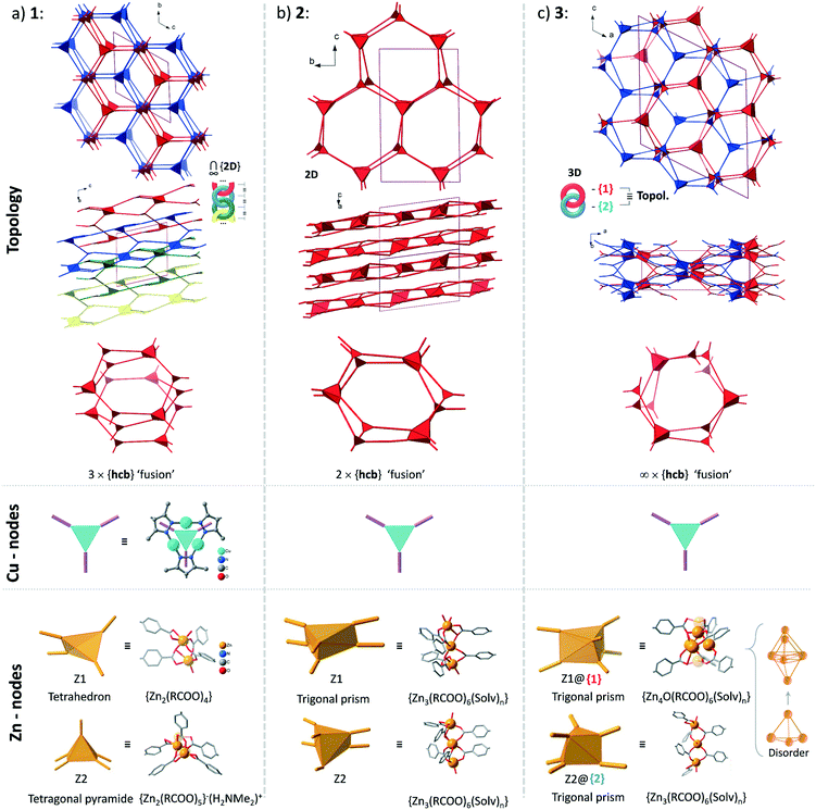 | ||
| Fig. 9 Topological overview of the structures of 1–3 (the coloration of the separate networks is assigned for convenience: all structures contain only one type of network regarding their topology). The crystallographically distinct Cu-based nodes are structurally- and in most cases topologically equivalent (the exception is the structure of 1, where there are two topologically distinct Cu-nodes among three crystallographically different ones with point symbols of {4·62} and {63}; see Table S4, ESI†). The Zn-based nodes are distinct in every case, except for the topological equivalence of the two different nodes in the structure of 3. For an illustration of the interpenetration of hexagonal rings in the structures of 1 and 3 see Fig. S15, ESI.† | ||
The Zn-SBU nuclearity increases from Zn2 in 1 over hourglass-like Zn3 in 2 to Zn3 and Zn4 in 3 (Fig. 9). The connectivity ensured by the Zn-SBU adapts to the demands imposed by the stacked CuI-mpba linker arrangement, conditioned by the cuprophilic interactions (Fig. S13, ESI†). The flexibility in the Zn coordination sphere with tetrahedral, trigonal-bipyramidal to square-planar or octahedral coordinated Zn atoms must be seen as instrumental to allow the formation of (energetically) similar structures.
From the topological analysis on the level of the 3-c {Cu3(pz)3} node and of the Zn-SBU nodes of higher connectedness, the next point symbols were found: {4·62}2{42·66·82}{63}{65·8} for 1 (a new 2D net), {43·612}{43}2 for 2 (3,6L66 net), and {4·6·8}2{42·65·85·103} for 3 (sqc-3,6-Fdd2-2 net) (the topological analysis was performed by ToposPro,67,68 see Fig. 9 for the node representations and Table S4, ESI,† for node stoichiometry, vertex symbols and TD10).
The structures of 1–3 could be conceptualized through their relation with the hexagonal net, hcb. The latter is an expected outcome, when the trigonal {Cu3(pz)3} SBUs are combined in a coplanar fashion. The cuprophilic interactions, perpendicular to the nets, would favor a stacked arrangement (the few reported structures of this kind are based on short non-planar bifunctional 3,5-R2-pyrazolates of copper(I),69,70 possessing 3D structures). The structures of 1–3 could be viewed as derivatives of the prototypal stacked hcb structure. Some of the alternating Cu-nodes are removed and the respective connectivity is added to the node in the layer above and/or below. The nodes with the increased connectivity are represented by a Zn-cluster and such redistribution of connectivity leads to ‘fusing’ of the separate hcb-nets. The Zn-clusters act as tetrahedral 4-c and tetragonal-pyramidal 5-c in 1 and trigonal-prismatic 6-c in 2 and 3 (Fig. 9). The Zn-clusters adopt different compositions and geometries, invariably ensuring the near coplanarity of the {Cu3(pz)3} SBUs within the columnar stacks, associated by cuprophilic interactions, that run uninterrupted through the whole structure (Fig. 4, 6c, 8c and S13, ESI†).
The simplest structural organization of ‘fused’ hcb nets is observed in 2 (Fig. 5, 6 and 9). The trigonal-prismatic Zn clusters correspond to two triangular nodes joined together in parallel. The resultant planar 2D net could be viewed as a “double-strand” (“dual-layer”) hcb net with two stacked nets fused together at alternating nodes. The Cu-nodes are associated by cuprophilic interactions both within the formed 2D network and between them forming a stack of networks, whose projection along the a-axis is nearly identical to a geometrically regular hcb net (Fig. 6 and 9). The structure features two crystallographically distinct, but chemically and topologically equivalent trinuclear Zn-clusters, {Zn3(COO)6}. Three chelating carboxylates adjoin the neighboring Zn atoms disposed in row of three; two sets of such triples are in an approximately staggered disposition, ensuring the trigonal-prismatic shape of the node (Fig. 5b and 9). Similar structural organization is observed for a number of other tritopic carboxylates featuring an {M3(COO)6} SBU/cluster or functionally very similar unit (M = Zn, Co, Cd) (among 32 entries with the 3,6L66 net topology found in the Topcryst database,71 nearly all are coordination polymers and 23 follow this organization; see also the footnote to Table S4†). We regard the 2-layer stack in 2 as the kinetic product from which the 3-layer stack in 1 and the infinite-layer stack in 3 develop.
The structure of 1 consists of 2D nets, which could be represented as a ‘fusion’ of three stacked hexagonal nets (Fig. 2 and 9). Half of the alternating nodes in the top and bottom layers are represented by 4-c and 5-c Zn-nodes (with an excess connectivity over 3-c of one and two, respectively), which distribute the connectivity of the imaginary triangular node in the middle layer. Each pair of the neighboring triple-layer stacks is polycatenated in a parallel fashion, with the Cu-nodes belonging to the neighboring topologies interdigitating to form a tight stack (Fig. 3 and 4). The triple-layered topologies are polycatenated via pairwise interpenetration and topologically constitute a 2D + 2D → 3D structure. The dinuclear Zn-nodes, {Zn2(RCOO)4} and {Zn2(RCOO)5} are close to a paddlewheel geometry with an added carboxylate in the second case, which is charge compensated by a nearby [Me2NH2]+ cation.
The structure of 3 consists of two interpenetrated 3D nets, which are crystallographically and chemically distinct, but topologically equivalent (Fig. 7). Thereby, it represents formally a case of hetero-interpenetration, even if the topologies are very similar. The ‘fusion’ of the imaginary stacked hcb nets takes place not on the same level, but on alternating levels. Each of the two different six connected Zn-clusters acts as a trigonal node within its layer (Fig. 9) and the remaining excess connectivity (2 + 1) is redistributed above and below, respectively, the layer at the expense of the imaginary Cu-nodes of the prototypal stacked hcb net structure. It is interesting to note that each of the two distinct 6-c connected trigonal-prismatic Zn-nodes, {Zn4O(RCOO)6} = Z1 and {Zn3(RCOO)6} = Z2 (cf.Fig. 9), belongs only to one of the two interpenetrating 3D nets. The Z2 node is similar to the one in 2, while Z1 is formally close to the expected zinc-oxidocarboxylate cluster (octahedral SBU at the highest symmetry) but with strong geometric distortions accompanied with a complex, not completely resolved crystallographic disorder (Fig. S11, ESI†). The binodal net observed in 3 is also known as the sqc-3,6-Fdd2-2 type sqc-subnet (for net relations, see ref. 72). It is relatively rare, with only five representatives known in the Topcryst database.71 All of them are dense coordination polymers based on short bi-azole azole-carboxylate ligands and bear no direct similarity in structural organization with 3. Hence the hetero-interpenetrated 3 is topologically unique as a MOF.
The general structure-formation logic for 1–3 explains the formation of a class of ‘fused’ hcb-nets rather than a singular compound. This class could be compared with the class of pillared hcb nets, which is also highly variable when the pillaring could occur both on one and both sides of the planes (connection isomerism). For the case of the ‘fused’ nets, which could be viewed as a zero-length pillaring, the variety stems from variable number of connections for a fused node (4–6 in this work).
The summary on topological characteristics of the nets in structures 1–3 is given in Table S4, ESI.† Except for the simple ‘dual-strand’ hcb net in 2, the other cases are highly special. It is instructive to observe the dominance of 4- and 6-rings (and their exclusivity as smaller cycles). This is the reflection of the ‘fused’ hcb structure-organization. When two stacked hcb nets are fused via alternating vertices a 4-ring is formed (Fig. S16, ESI†). It is a sole outcome for the case of 2 with only one pair of fused-hcb nets, but larger rings appear when the fusing of the hcb-layers occurs on different levels as in 1 and 3.
An aspect which should not be overlooked is the flexibility of the {CuI3(mpba)3}3− metallo-linker, which surpasses the bbc3− and bte3− flexibilities (vide supra, Fig. S44, ESI†). This flexibility can be characterized in terms of separate contributors, as a system of rigid elements, connected by hinges.73 The flexibility factors regarding the {CuI3(mpba)3}3− metallo-linker are based on (i) the {Cu3(pz)3} cluster level off-plane deformations, (ii) an equivalent flexibility of the phenyl connectors to the carboxylate group, and (iii) the flexibility due to a rotational degree of freedom between the pyrazolate and phenyl moieties. In the example structure of 2, with its four crystallographically different {CuI3(mpba)3}3− metallo-linkers, the benzoate groups bend out of the plane through the three Cu atoms by 0.7° to 14.5°, most of them between 6° and 8° (Fig. S45, ESI†).
Cu/Zn analysis
In view of the disorder in the Zn-SBUs of all three compounds (cf.Fig. 1, 3b and 7b, see also Fig. S4, S9 and S11, ESI†) the elemental analysis of the Cu![[thin space (1/6-em)]](https://www.rsc.org/images/entities/char_2009.gif) :
:![[thin space (1/6-em)]](https://www.rsc.org/images/entities/char_2009.gif) Zn ratio and the confirmation of the sole presence of the Cu(I) oxidation state (exclusion of Cu(II)) became important. It seemed necessary to ensure that the Zn-SBUs were indeed Zn-only SBUs with no admixture of Cu(II).
Zn ratio and the confirmation of the sole presence of the Cu(I) oxidation state (exclusion of Cu(II)) became important. It seemed necessary to ensure that the Zn-SBUs were indeed Zn-only SBUs with no admixture of Cu(II).
The X-ray photoelectron survey spectra (Fig. S23, ESI†) confirm the expected presence of Cu, Zn, O, N and C in the materials. The Cu 2p XP spectra for all three compounds display the core band at around 933 eV for Cu 2p3/2 which corresponds to the typical position of Cu(I) (Fig. S24a–S26a, ESI†).74 The near perfect single-peak fit indicates the presence of only one type of Cu(I) species. Cu(II) species are not present in any of the compounds, according to the absence of the characteristic band at ∼934 eV in the Cu 2p XP spectra.74 The band at ∼1022 eV in the 2p XPS spectra corresponds to Zn(II) and is observed for all three materials (Fig. S24b–S26b, ESI†).75
The shape of the Cu LMM peak from the Auger electrons can also be useful in determining the chemical state of Cu. It is particularly indicative in the determination of Cu metal versus Cu(I) in the absence of Cu(II) species.76 The Cu-LMM peak is observed at a kinetic energy of 916.5 eV in the Auger spectrum, which is a part of the XP spectrum (Fig. S27, ESI†). The modified Auger parameter α′ was calculated by adding the binding energy of the Cu 2p3/2 photoelectron peak and the kinetic energy of the Cu L3M45M45 Auger peak.76 The value of the modified Auger-α′ parameter for Cu LMM and the Cu 2p3/2 electron was about (933 + 916.5 =) 1849 eV, which confirmed the +1 oxidation state of Cu.77,78 For Cu(II) the Auger kinetic energy should lie at 918 eV and the modified Auger-α' parameter should be about 1851 eV.77,78 The value of the modified Auger-α′ parameter for Zn LMM (988 eV, Fig. S28, ESI†) and the Zn 2p3/2 electrons (1022 eV) was approximately 2010 eV, which also confirms the +2 oxidation state of Zn.75,79
The fitting of the C 1s spectra (Fig. S29, ESI†) yielded three bands centered at 285, 286 and 289 eV which can be assigned to C–H/C–C/C![[double bond, length as m-dash]](https://www.rsc.org/images/entities/char_e001.gif) C, C–N, and –COO, respectively.80 The O 1s band observed at 531 eV (Fig. S29, ESI†) is due to Zn-bound oxygen, whereas the band at around 533 eV represents organic C–O.81,82 The fitting of the N 1s curves shows two types of component peaks (Fig. S29, ESI†), with the major contribution corresponding to Cu–N (399 eV) and the minor one to amide N–(C
C, C–N, and –COO, respectively.80 The O 1s band observed at 531 eV (Fig. S29, ESI†) is due to Zn-bound oxygen, whereas the band at around 533 eV represents organic C–O.81,82 The fitting of the N 1s curves shows two types of component peaks (Fig. S29, ESI†), with the major contribution corresponding to Cu–N (399 eV) and the minor one to amide N–(C![[double bond, length as m-dash]](https://www.rsc.org/images/entities/char_e001.gif) O) (400 eV) from coordinated and residual DMF solvent molecules.83
O) (400 eV) from coordinated and residual DMF solvent molecules.83
From atomic absorption spectroscopy (AAS) (Table S5, ESI†) and scanning electron microscopy energy-dispersive X-ray spectroscopy (SEM-EDX) (Section S17–S20, ESI,† Tables S6 and S7 ESI†), the molar Cu![[thin space (1/6-em)]](https://www.rsc.org/images/entities/char_2009.gif) :
:![[thin space (1/6-em)]](https://www.rsc.org/images/entities/char_2009.gif) Zn ratio for 1 was 1
Zn ratio for 1 was 1![[thin space (1/6-em)]](https://www.rsc.org/images/entities/char_2009.gif) :
:![[thin space (1/6-em)]](https://www.rsc.org/images/entities/char_2009.gif) 0.44 (AAS) and 1
0.44 (AAS) and 1![[thin space (1/6-em)]](https://www.rsc.org/images/entities/char_2009.gif) :
:![[thin space (1/6-em)]](https://www.rsc.org/images/entities/char_2009.gif) 0.44 (EDX, Table S4, ESI†), which is in good agreement with the expectation from the X-ray refinement (Cu
0.44 (EDX, Table S4, ESI†), which is in good agreement with the expectation from the X-ray refinement (Cu![[thin space (1/6-em)]](https://www.rsc.org/images/entities/char_2009.gif) :
:![[thin space (1/6-em)]](https://www.rsc.org/images/entities/char_2009.gif) Zn = 9
Zn = 9![[thin space (1/6-em)]](https://www.rsc.org/images/entities/char_2009.gif) :
:![[thin space (1/6-em)]](https://www.rsc.org/images/entities/char_2009.gif) 4 = 1
4 = 1![[thin space (1/6-em)]](https://www.rsc.org/images/entities/char_2009.gif) :
:![[thin space (1/6-em)]](https://www.rsc.org/images/entities/char_2009.gif) 0.44). For 3 the analyses gave 1
0.44). For 3 the analyses gave 1![[thin space (1/6-em)]](https://www.rsc.org/images/entities/char_2009.gif) :
:![[thin space (1/6-em)]](https://www.rsc.org/images/entities/char_2009.gif) 0.53 (AAS) and 1
0.53 (AAS) and 1![[thin space (1/6-em)]](https://www.rsc.org/images/entities/char_2009.gif) :
:![[thin space (1/6-em)]](https://www.rsc.org/images/entities/char_2009.gif) 0.53 (EDX, Table S3, ESI†), slightly below the value from the X-ray refinement (Cu
0.53 (EDX, Table S3, ESI†), slightly below the value from the X-ray refinement (Cu![[thin space (1/6-em)]](https://www.rsc.org/images/entities/char_2009.gif) :
:![[thin space (1/6-em)]](https://www.rsc.org/images/entities/char_2009.gif) Zn = 12
Zn = 12![[thin space (1/6-em)]](https://www.rsc.org/images/entities/char_2009.gif) :
:![[thin space (1/6-em)]](https://www.rsc.org/images/entities/char_2009.gif) 7 = 1
7 = 1![[thin space (1/6-em)]](https://www.rsc.org/images/entities/char_2009.gif) :
:![[thin space (1/6-em)]](https://www.rsc.org/images/entities/char_2009.gif) 0.58).
0.58).
Thermogravimetric and gas sorption studies
Thermogravimetric analysis (TGA) of the as-synthesized material 1 (Fig. S21a, ESI†) showed a mass loss of 18 wt% up to ∼300 °C, which can be attributed to the loss of 9 DMF molecules (calc. 17.8% for 9 DMF). This is in good agreement with the refined coordinated (2 DMF) and SQUEEZE-removed DMF molecules (∼7.5 DMF, Table S2, ESI†) per formula unit. For compound 2, TGA gave a mass loss of 26 wt% up to ∼270 °C, which can be ascribed to the loss of 18 DMF molecules (calc. 26.1% for 18 DMF) (Fig. S21b, ESI†). This agrees well with the found (5 DMF) and SQUEEZE-removed DMF molecules (∼14 DMF, Table S2, ESI†) per formula unit. The TGA of the as-synthesized material 3 (Fig. S21b, ESI†) exhibited a mass loss of 20% up to ∼300 °C, which can be attributed to the loss of 14 DMF molecules (calc. 20.0% for 13.6 DMF). This result is in acceptable agreement with the refined (3 DMF) and squeezed (∼12 DMF, Table S2, ESI†) DMF molecules per formula unit. The TGA of the activated compound 3-act. (Fig. S21b, ESI†) did not exhibit any mass loss up to ∼300 °C. After 300 °C decomposition of all three materials occurred with a mass loss up to 300 °C of 25–30 wt% (Fig. S21, ESI†).In view of the structural similarity of 1–3 regarding the formation of hexagonal nets in staggered stacking mode (Fig. 3b for 1, Fig. 6b for 2 and Fig. 8a for 3; Fig. S13 for comparison) it is no surprise that all three compounds yield a similar specific surface area from a crystal void calculation with CrystalExplorer84 and a similar specific pore volume from CrystalExplorer, Mercury85,86 and PLATON87 (Table S11, ESI†).
Various attempts to activate 1 and to prove the presence of a porous material were not successful. Either direct activation in a vacuum under heating or milder approaches via preceding solvent exchange or supercritical drying yielded amorphous materials (1-act. Fig. S3, ESI†) which did not demonstrate appreciable Ar (87 K) or CO2 (195 K) adsorption.
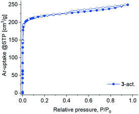
The activation attempts of 3 by heating under vacuum were more successful, and the resultant 3-act. material demonstrated significant crystallinity, even if inferior to 3 as judged by the peak broadening in the PXRD pattern (Fig. S3, ESI†). The latter also witnesses a structural transformation caused by the loss of solvent molecules (Fig. S21b, ESI†). The two-fold interpenetrated 3D framework in 3 expectedly provides higher structural resilience and prevents a complete structural collapse compared to the polycatenated 2D framework in 1. But even in 3 there is no prerequisite for a highly rigid structure because of the ligand flexibility (vide supra). Notwithstanding the crystallinity, 3-act. demonstrated only a small N2 uptake at 77 K with a hysteresis spanning the whole measurement range, indicating kinetic hindrances (Fig. S30, ESI†). At 87 K (liquid argon temperature) argon fills narrow micropores at significantly higher relative pressures in comparison with nitrogen at 77 K.88,89 Accordingly, Ar with also a smaller kinetic diameter (3.4 vs. 3.64 Å for N2) and weaker interaction with the adsorbent implying faster equilibration rates compared to N2 was selected for further studies. The adsorption of Ar at 87 K by 3-act. was indeed unhindered, followed a type I isotherm (Fig. 10) and allowed for BET surface analysis. The material possesses a total pore volume of 0.30 cm3 g−1 at P/P0 = 0.95, a micro pore volume of 0.25 cm3 g−1 at P/P0 = 0.1, and a BET surface area of 762 m2 g−1 (Fig. S31b, ESI†). The desorption shows a small hysteresis loop (type H4) which is typical for micro-mesoporous materials.89
CO2 (and also CH4) gas sorption studies were performed for the 3-act. material at 273 K and 293 K. Due to the higher temperatures only minor kinetic hindrances were observed. The adsorption isotherms are of type Ia (Fig. 11), albeit not reaching saturation for CO2 at 1 bar, which again underlines the microporous character of the material.
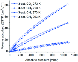 | ||
| Fig. 11 CO2 and CH4 sorption isotherms of 3-act. at 293 K and 273 K with adsorption as filled symbols and desorption as open symbols. | ||
As expected, the uptake of the slightly larger non-polar gas CH4 was significantly lower with 15 cm3 g−1 (273 K) and 14 cm3 g−1 (293 K) than for CO2 78 cm3 g−1 (273 K) and 46 cm3 g−1 (293 K). Consequently, the determined CO2![[thin space (1/6-em)]](https://www.rsc.org/images/entities/char_2009.gif) :
:![[thin space (1/6-em)]](https://www.rsc.org/images/entities/char_2009.gif) CH4 selectivity by the Henry plots of the adsorption isotherms results in a higher selectivity for CO2 (4.8
CH4 selectivity by the Henry plots of the adsorption isotherms results in a higher selectivity for CO2 (4.8![[thin space (1/6-em)]](https://www.rsc.org/images/entities/char_2009.gif) :
:![[thin space (1/6-em)]](https://www.rsc.org/images/entities/char_2009.gif) 1 at 273 K, 3.5
1 at 273 K, 3.5![[thin space (1/6-em)]](https://www.rsc.org/images/entities/char_2009.gif) :
:![[thin space (1/6-em)]](https://www.rsc.org/images/entities/char_2009.gif) 1 at 293 K; Fig. S32, Table S10, ESI†).
1 at 293 K; Fig. S32, Table S10, ESI†).
The isosteric enthalpy of adsorption at zero coverage, ΔH0ads for CO2 and CH4 from adsorption isotherms at 273–293 K (Fig. 11) was calculated with the virial fit method (Fig. S33 and S34, ESI†).90 As expected, the values of the isosteric enthalpy of adsorption ΔHads are significantly higher (i.e. more negative) for CO2 than for CH4 at the same gas uptake. At zero coverage ΔH0ads (CO2) is −29 kJ mol−1 and ΔH0ads(CH4) is −15 kJ mol−1. Compared to other MOFs, these values are at the lower end for ΔH0ads.91–93
Conclusions
The N,O-heteroditopic semi-flexible mbpa3− ligand with carboxylate and dimethylpyrazolate tails was used for the exploration of mixed-metal Cu(I)/Zn(II) coordination networks, aiming to combine the probable {Cu3(3,5-dimethylpyrazolate)3 and Zn4O(O2C)6 SBUs. An alternative viewpoint on the synthesis in polar media is the in situ formation of the {CuI3(mpba)3}3− metallo-ligand, as an intermediate product, which is engaged in minimal ligand-exchange concurrence in a hard-ligand environment. Accordingly, {CuI3(mpba)3}3− is viewed as a large triangular ligand, interesting in the context of reticular chemistry, where 1,3,5-benzenetricarboxylate and expanded analogues play an important role.Three coordination networks, 1–3, were obtained in a course of low-temperature solvothermal synthesis from N,N-dimethylformamide and, remarkably, there is a condition-range when all the three compounds formed simultaneously. In all compounds columnar stacks of Cu3(3,5-dimethylpyrazolate)3 clusters associated by cuprophilic interactions are the dominant structural feature. Parallel orientation of the stacks is the most general way to achieve an efficient packing; the various 2-4(5)-nuclear Zn-SBUs are rather adapting to this requirement. The resulting networks bear similarities to stacked hcb nets, which would be realized for trigonal SBU-only assembly. The additional connectivities of the Zn-SBU clusters ‘fuse’ the hcb nets together, yielding layered 2D, layered polycatenated 2D → 3D or 3D frameworks. Despite the interpenetration, the permanent porosity for 3 with a 3D porous structure was demonstrated by Ar, CO2 and CH4 sorption.
Thus, the structures 1–3 demonstrate similar underlying network-formation principles resulting in what could be named a ‘fused’ hcb structure class. The structure prediction could be only fuzzy or vague here, and yet such limited design accuracy could be productive. The {CuI3(mpba)3}3− metallo-linker has structural degrees of freedom which allow for certain self-adjustments regarding the relative angular positions of the carboxylate groups and this appears favorable for an explorative search approach not based on an exact prediction of a particular structural type. Further elongation of the ligand might yield similar structures due to the good stabilization granted by the cuprophilic stacking. Interesting possibilities of defective structures could be foreseen by using co-ligands with terminated connectivity, like [Cu3(3,5-dimethylpyrazolate)3], which could be incorporated in the stacks and decrease the general connectivity.
It is worth stressing the interest in mixed-metal MOFs based on heteroditopic ligands. In the case of mbpa, the CuI/AlIII combination seems to be particularly interesting due to the multitude of possible aluminum oxidocarboxylate MOFs. Another interesting aspect is the use of the limited-prediction approach when a dominant self-assembly factor is present and the semi-flexible ligands/clusters allow for some self-adjustment (ligands with a high level of flexibility are generally not compatible with permanent porosity). For example, for the octahedral {Zn4O(COO)6} and the triangular planar {CuI3(pz)3} SBUs a multitude of combination possibilities exist, provided that certain self-adjustment is possible. Among the suitable alternating two vertex 3,6-c nets, the rutile rtl net possesses the highest symmetry and suitable node geometries, however its demands an adjusting turn of the neighboring SBUs by ∼45°, which could be supported by the mbpa moiety of the {CuI3(mpba)3}3− linker. Despite a multitude of possibilities, all three obtained compounds 1–3 follow the same structure-formation logic: the cuprophilic interactions between the {CuI3(pz)3} SBUs, frequently occurring for such structures, evidently play an important pre-organizing role and dictate the course of the self-assembly, which is allowed by the geometric self-adjustment provided by the ligand and concomitant flexible cluster actualization.
Experimental section
Chemicals
Reagents and solvents were obtained from commercial sources and used as received without further purification. Cu(NO3)2·2.5H2O (98%) was purchased from Alfa Aesar, Zn(NO3)2·4H2O (98%) from ALFA Chemistry and Zn(CH3COO)2·2H2O (98%) from VWR. N,N-Dimethylformamide (DMF) p.a. was obtained from Riedel-de Haën, tetrafluoroboric acid (HBF4, 48 wt% in H2O) from Sigma-Aldrich and conc. nitric acid from Chemsolute. The synthesis of 4-(3,5-dimethyl-1H-pyrazol-4-yl)benzoic acid (H2mpba) was carried out according to the literature procedure.45Instrumentation
Elemental analysis measurements of carbon, hydrogen, nitrogen and sulfur (CHNS) were done with an Elementar Vario MICRO cube. IR-spectra were recorded on a Bruker FT-IR Tensor 37 spectrometer in the 4000–500 cm−1 region with 2 cm−1 resolution as KBr disks. Powder X-ray diffraction (PXRD) measurements were carried out with a Rigaku MiniFlex600 powder diffractometer using a flat silicon, low background sample holder at 40 kV, 60 mA (600 W) for Cu-Kα radiation (λ = 1.54184 Å). In all diffractograms, the most intense reflection was normalized to 1. Simulated powder X-ray diffractograms were obtained from single-crystal data using the MERCURY 3.5.1 software program.94 Thermogravimetric analysis (TGA) was performed using a Netzsch TG 209 F3 Tarsus from 20 to 600 °C with a heating range of 5 K min−1 under nitrogen atmosphere. Atomic absorption spectroscopy (AAS) was carried out on a PinAAcle 900T from Perkin-Elmer with a copper or zinc hollow cathode in acetylene/air-flame at 2300 °C. Scanning electron microscopy (SEM) images were obtained using a Jeol JSM-6510LV QSEM advanced electron microscope equipped with a LaB6 cathode at 5–20 kV. The microscope was equipped with a Bruker Xflash 410 silicon drift detector for energy-dispersive X-ray (EDX) spectroscopy. The samples were coated with gold (Au) using a Jeol JFC 1200 finecoater (20 mA for 25 s) before the measurements. X-ray photoelectron spectroscopy (XPS) measurements were made on an ULVAC-PHI VersaProbe II microfocus X-ray photoelectron spectrometer. Experimental XP spectra were fitted by the CasaXPS program, version 2.3.19PR1.0, copyright 1993–2018 Casa Software Ltd. Volumetric gas sorption measurements up to one bar were performed on a Quantachrome Autosorb iQ MP on sample amounts of at least 30 mg, which were degassed/activated under vacuum (10−3 mbar) at 200 °C, for 3 h.Single crystal X-ray structure determination
For 2 and 3, the single-crystal diffraction data was collected using a Rigaku XtaLAB Synergy S four-circle diffractometer with a Hybrid Pixel Array Detector and a PhotonJet X-ray source for Cu-Kα radiation (λ = 1.54184 Å) with a multilayer mirror monochromator. The data were collected under a cold nitrogen gas-stream at 100.0(1) K using ω-scans. Data reduction and absorption correction were performed by CrysAlisPro 1.171.41.61a [Rigaku Oxford Diffraction, 2020 Yarnton, UK].
All three structures were solved by direct methods using SHELXT-2015.97 Full-matrix least squares refinements on F2 were carried out with SHELXL-2015. Crystal data and details on the structure refinement are given in Table S2, ESI.† Graphics were drawn with the program Diamond.98 The structure of 3 was refined as a 2-component inversion twin.
In 1–3 in favour of clarity, the mpba2− units and DMF molecules were organized in residues (RESI). All hydrogen atoms were positioned geometrically and refined using riding models with Uiso(H) = 1.2·Ueq(CHarom.)/Ueq(NH) or 1.5·Ueq(CH3).
In 1–3 highly disordered solvent molecules were removed via the SQUEEZE (Platon) procedure (structures 1 and 3)87 or by solvent masking as implemented in OLEX 2 (structure 2). In 1 the resulting solvent accessible volume of 2751 Å3 per unit cell contained 604 electrons, which may correspond to 15 DMF molecules (40 e− each) as the solvent of crystallization per unit cell or 7.5 DMF molecules per given asymmetric formula unit (Z = 2). In 2 the resulting solvent accessible volume of 4630 Å3 per unit cell contained 1131 electrons, which may correspond to 28 DMF molecules as the solvent of crystallization per unit cell or 14 DMF molecules per given asymmetric formula unit (Z = 2). In 3 the resulting solvent accessible volume of 7369 Å3 per unit cell contained 1894 electrons, which may correspond to 47 DMF molecules as the solvent of crystallization per unit cell or ∼12 DMF molecules per given asymmetric formula unit (Z = 4).
In 1 the Zn-cluster which contains the dimethylamine and dimethylammonium species which are disordered in an 81![[thin space (1/6-em)]](https://www.rsc.org/images/entities/char_2009.gif) :
:![[thin space (1/6-em)]](https://www.rsc.org/images/entities/char_2009.gif) 19 ratio, affecting both Zn atoms and the proton of the counterion.
19 ratio, affecting both Zn atoms and the proton of the counterion.
In 2 the phenyl rings of RESI 5, 9 and 12 are disordered over two positions due to rotation along the 1,4-axis which is a well-known phenomenon. Furthermore, one DMF molecule coordinating to Zn4 is disordered over two positions in an 86![[thin space (1/6-em)]](https://www.rsc.org/images/entities/char_2009.gif) :
:![[thin space (1/6-em)]](https://www.rsc.org/images/entities/char_2009.gif) 14 ratio.
14 ratio.
In 3 the zinc oxidocarboxylate coordination-bonded cluster ({Zn4O}) involving the Zn4 to Zn8a,b atoms features a complex disorder, which could be described in the first approximation as three overlapping {Zn4O} arrangements. The disorder is driven by the demand imposed by the crystal structure/topology: six carboxylates, which are located within convenient reach, are not arranged suitably to sustain the regular octahedral {Zn4O(RCOO)6} cluster. The ‘three overlapping pyramids’ model with a nearly common base (Zn5, Zn6, Zn7) assumes a much lower occupancy of the ‘capping/axial’ Zn-atoms (Zn4, Zn8a,b), however the refined equivalent Uiso values do not indicate dramatic differences. While the relatively large temperature factors could mask additional non-evident disorder possibilities, there is another possible reason for the higher occupancy of the ‘capping’ atoms: at least for Zn8 there is a weak residual electronic density in the vicinity. Instead of speculating the possibility of an increased number of Zn atoms in the cluster, the disorder was modelled as even via ascribing 0.8 occupancy for each of the five Zn atoms (the Zn8 atom is additionally split into two components, Zn8a and Zn8b, with refined contributions). This concise approach reflects both the experimental observations and the limited knowledge about disorder, whose occurrence is, however, not unusual in the given structural setting. Accordingly, the cluster composition, involving the Zn4 to Zn8a,b atoms, is assumed to be {Zn4O(H2O/DMF)4(RCOO)6}. The coordinated water molecules (O5S to O8S atoms) are a simplified description of site-sharing H2O/DMF ligands; the too weak residual electron density made the refinement of the DMF constituents not practical.
The structural data have been deposited with the Cambridge Crystallographic Data Center under deposition numbers CCDC 2105164–2105166.†
Synthetic procedures
Author contributions
This manuscript was written through contributions of all the authors. All the authors have given approval to the final version of this manuscript.Conflicts of interest
There are no conflicts to declare.Acknowledgements
The authors thank Mrs Birgit Tommes for carrying out the FT-IR experiments and Annette Ricken for the AAS measurements. Dr. Christian Schürmann (Rigaku) and Dr. Tobias Stürzer (Bruker AXS) are thanked for their crucial crystal-screening and data-collection efforts. The Rigaku X-ray diffractometer was funded by the Deutsche Forschungsgemeinschaft (DFG, German Research Foundation) through project number 440366605. We thank the CeMSA@HHU (Center for Molecular and Structural Analytics@Heinrich Heine University) for recording the mass-spectrometric and the NMR-spectroscopic data.Notes and references
- O. K. Farha and J. T. Hupp, Acc. Chem. Res., 2010, 43, 1166–1175 CrossRef CAS PubMed.
- M. Taddei, Coord. Chem. Rev., 2017, 343, 1–24 CrossRef CAS.
- J. D. Evans, B. Garai, H. Reinsch, W. Li, S. Dissegna, V. Bon, I. Senkovska, R. A. Fischer, S. Kaskel, C. Janiak, N. Stock and D. Volkmer, Coord. Chem. Rev., 2019, 380, 378–418 CrossRef CAS.
- J. R. Long and O. M. Yaghi, Chem. Soc. Rev., 2009, 38, 1213–1214 RSC.
- X. Han, S. Yang and M. Schröder, Nat. Rev. Chem., 2019, 3, 108–118 CrossRef CAS.
- S. R. Batten, N. R. Champness, X.-M. Chen, J. Garcia-Martinez, S. Kitagawa, L. Öhrström, M. O'Keeffe, M. Paik Suh and J. Reedijk, Pure Appl. Chem., 2013, 85, 1715–1724 CrossRef CAS.
- H.-C. J. Zhou and S. Kitagawa, Chem. Soc. Rev., 2014, 43, 5415–5418 RSC.
- S. S. Y. Chui, S. M. F. Lo, J. P. H. Charmant, A. G. Orpen and I. D. Williams, Science, 1999, 283, 1148–1150 CrossRef CAS PubMed.
- L. Xie, S. Liu, B. Gao, C. Zhang, C. Sun, D. Li and Z. Su, Chem. Commun., 2005, 2402–2404 RSC.
- L. H. Xie, J. B. Lin, X. M. Liu, W. Xue, W. X. Zhang, S. X. Liu, J. P. Zhang and X. M. Chen, Sci. China: Chem., 2010, 53, 2144–2151 CrossRef CAS.
- C. Ordonez, M. Fonari, J. Lindline, Q. Wei and T. Timofeeva, Cryst. Growth Des., 2014, 14(11), 5452–5465 CrossRef CAS.
- W. W. Lestari, M. Arvinawati, R. Martien and T. Kusumaningsih, Mater. Chem. Phys., 2018, 204, 141–146 CrossRef CAS.
- H. K. Chae, D. Y. Siberio-Pérez, J. Kim, Y. B. Go, M. Eddaoudi, A. J. Matzger, M. O'Keeffe and O. M. Yaghi, Nature, 2004, 427, 523–527 CrossRef CAS PubMed.
- H. Furukawa, M. A. Miller and O. M. Yaghi, J. Mater. Chem., 2007, 17, 3197–3204 RSC.
- I. M. Hauptvogel, V. Bon, R. Grünker, I. A. Baburin, I. Senkovska, U. Mueller and S. Kaskel, Dalton Trans., 2021, 41, 4172–4179 RSC.
- Z. W. Wei, D. Q. Yuan, X. L. Zhao, D. F. Sun and H.-C. Zhou, Sci. China: Chem., 2013, 56, 418–422 CrossRef CAS.
- B. Chen, M. Eddaoudi, S. T. Hyde, M. O'Keeffe and O. M. Yaghi, Science, 2001, 291, 1021–1023 CrossRef CAS PubMed.
- H. Furukawa, Y. B. Go, N. Ko, Y. K. Park, F. J. Uribe-Romo, J. Kim, M. O'Keeffe and O. M. Yaghi, Inorg. Chem., 2011, 50, 9147–9152 CrossRef CAS PubMed.
- K. Gedrich, I. Senkovska, N. Klein, U. Stoeck, A. Henschel, M. R. Lohe, I. A. Baburin, U. Mueller and S. Kaskel, Angew. Chem., Int. Ed., 2010, 49, 8489–8492 CrossRef CAS PubMed.
- H. Furukuwa, N. Ko, Y. B. Go, N. Aratani, S. B. Choi, E. Choi, A. O. Yazaydin, R. Q. Snurr, M. O'Keeffe, J. Kim and O. M. Yaghi, Science, 2010, 329, 424–428 CrossRef PubMed.
- J. Wang, C. Rao, L. Lu, S. Zhang, M. Muddassir and J. Liu, CrystEngComm, 2021, 23, 741–747 RSC.
- M. Wang, J. Liu, J. Jin, D. Wu, G. Yang, W.-Y. Zhang and Y.-Y. Wang, CrystEngComm, 2021, 23, 663–670 RSC.
- W. Li and J.-S. Tan, J. Mol. Struct., 2021, 1237, 130359 CrossRef CAS.
- R. A. Agarwal, Cryst. Growth Des., 2021, 21, 2046–2055 CrossRef CAS.
- M.-H. Tang, Y. Shi, X.-L. Jiang, H. Xu, Y. Ma and B. Zhao, J. Mater. Chem. C, 2021, 9, 9643–9649 RSC.
- E. Lopez-Maya, N. M. Padial, J. Castells-Gil, C. R. Ganivet, A. Rubio-Gaspar, F. G. Cirujano, N. Almora-Barrios, S. Tatay, S. Navalon and C. Marti-Gastaldo, Angew. Chem., Int. Ed., 2021, 60, 11868–11873 CrossRef CAS PubMed.
- J. Chen, T. Chen, S. Xiang, J. Zhang and Z. Zhang, Z. Anorg. Allg. Chem., 2021, 647, 1301–1304 CrossRef CAS.
- D. Sun, Y. Ke, T. M. Mattox, S. Parkin and H.-C. Zhou, Inorg. Chem., 2006, 45, 7566–7568 CrossRef CAS PubMed.
- D. Saha, R. Zacharia, L. Lafi, D. Cossement and R. Chahine, Int. J. Hydrogen Energy, 2012, 37, 5100–5107 CrossRef CAS.
- S. Lee, H.-B. Bürgi, S. A. Alshmiri and O. M. Yaghi, J. Am. Chem. Soc., 2018, 140, 8958–8964 CrossRef CAS PubMed.
- J. Rong, W. Zhang and J. Bai, CrystEngComm, 2016, 18, 7728–7736 RSC.
- D. Sun, S. Ma, Y. Ke, D. J. Collins and H.-C. Zhou, J. Am. Chem. Soc., 2006, 128, 3896–3897 CrossRef CAS.
- S. Ma and H.-C. Zhou, J. Am. Chem. Soc., 2006, 128, 11734–11735 CrossRef CAS.
- R. R. R. Prasad, C. Pleass, A. L. Rigg, D. B. Cordes, M. M. Lozinska, V. M. Georgieva, F. Hoffmann, A. M. Z. Slawin and P. A. Wright, CrystEngComm, 2021, 23, 804–812 RSC.
- T. Liu, X. Shen, X. Shen, C. He, J. Liu and J.-J. Liu, CrystEngComm, 2021, 23, 4667–4673 RSC.
- K. Wang, S. Wang, J. Liu, Y. Guo, F. Mao, H. Wu and Q. Zhang, ACS Appl. Mater. Interfaces, 2021, 13, 15315–15323 CrossRef CAS PubMed.
- A. M. Toader, M. C. Buta, F. Cimpoesu, A.-I. Toma, C. M. Zalaru, L. O. Cinteza and M. Ferbinteanu, Chemistry, 2021, 3, 411–439 CrossRef CAS.
- N. V. S. Harisomayajula, S. Makovetskyi and Y.-C. Tsai, Chem. – Eur. J., 2019, 25, 8936–8954 CrossRef CAS PubMed.
- K. Singh, J. R. Long and P. Stavropoulos, J. Am. Chem. Soc., 1997, 119, 2942–2943 CrossRef CAS.
- (a) S. M.-F. Lo, S. S.-Y. Chui, L.-Y. Shek, Z. Y. Lin, X. X. Zhang, G.-H. Wen and I. D. Williams, J. Am. Chem. Soc., 2000, 122, 6293–6294 CrossRef CAS; (b) X.-C. Huang, J.-P. Zhang, Y.-Y. Lin, X.-L. Yua and X. M. Chen, Chem. Commun., 2004, 1100–1101 RSC; (c) K. Tomar, A. Verma and P. K. Bharadwaj, Cryst. Growth Des., 2018, 18, 2397–2404 CrossRef CAS; (d) N. Grosjean, C. Descorme and M. Besson, Appl. Catal., B, 2010, 97, 276–283 CrossRef CAS.
- C.-T. He, P.-Q. Liao, D.-D. Zhou, B.-Y. Wang, W.-X. Zhang, J.-P. Zhang and X.-M. Chen, Chem. Sci., 2014, 5, 4755–4762 RSC.
- Z.-M. Ye, C.-T. He, Y.-T. Xu, R. Krishna, Y. Xie, D.-D. Zhou, H.-L. Zhou, J.-P. Zhang and X.-M. Chen, Cryst. Growth Des., 2017, 17, 2166–2171 CrossRef CAS.
- C. Heering, I. Boldog, V. Vasylyeva, J. Sanchiz and C. Janiak, CrystEngComm, 2013, 15, 9757–9768 RSC.
- S. Menzel, S. Millan, S.-P. Höfert, A. Nuhnen, S. Gökpinar, A. Schmitz and C. Janiak, Dalton Trans., 2020, 49, 12854–12864 RSC.
- M. R. Bryant, A. D. Burrows, C. M. Fitchett, C. S. Hawes, S. O. Hunter, L. L. Keenan, D. J. Kelly, P. E. Kruger, M. F. Mahon and C. Richardson, Dalton Trans., 2015, 44, 9269–9280 RSC.
- C. Wang, C. Liu, H.-R. Tian, L.-J. Li and Z.-M. Sun, Chem. – Eur. J., 2018, 24, 2952–2961 CrossRef CAS PubMed.
- (a) A. E. Martell and R. D. Hancock, in Metal Complexes in Aqueous Solutions, ed. J. P. Fackler, Plenum Press, 1996 CrossRef; (b) R. B. Martin, in Encyclopedia of Inorganic Chemistry, ed. R. B. King, Wiley, 1994, pp. 2185–2189 Search PubMed; (c) R. H. Crabtree, in Encyclopedia of Inorganic Chemistry, ed. R. B. King, Wiley, 1994, p. 809 Search PubMed.
- B. Tu, Q. Pang, H. Xu, X. Li, Y. Wang, Z. Ma, L. Wenig and Q. Li, J. Am. Chem. Soc., 2017, 139, 7998–8007 CrossRef CAS PubMed.
- B. Tu, L. Diestel, Z.-L. Shi, W. R. L. N. Bandara, Y. Chen, W. Lin, Y.-B. Zhang, S. G. Telfer and Q. Li, Angew. Chem., Int. Ed., 2019, 58, 5348–5353 CrossRef CAS PubMed.
- J. Fritzsche, D. Denysenko, M. Grzywa and D. Volkmer, Dalton Trans., 2017, 46, 14907–14915 RSC.
- S. Menzel, S.-P. Höfert, S. Öztürk, A. Schmitz and C. Janiak, Z. Anorg. Allg. Chem., 2021, 647, 803–808 CrossRef CAS.
- (a) S. M.-F. Lo, S. S.-Y. Chui, L.-Y. Shek, Z. Y. Lin, X. X. Zhang, G.-H. Wen and I. D. Williams, J. Am. Chem. Soc., 2000, 122, 6293–6294 CrossRef CAS; (b) X.-C. Huang, J.-P. Zhang, Y.-Y. Lin, X.-L. Yua and X. M. Chen, Chem. Commun., 2004, 1100–1101 RSC; (c) K. Tomar, A. Verma and P. K. Bharadwaj, Cryst. Growth Des., 2018, 18, 2397–2404 CrossRef CAS; (d) N. Grosjean, C. Descorme and M. Besson, Appl. Catal., B, 2010, 97, 276–283 CrossRef CAS.
- H. Li, M. Eddaoudi, T. L. Groy and O. M. Yaghi, J. Am. Chem. Soc., 1998, 120, 8571–8572 CrossRef CAS.
- J. Xiao, H. Zhou and A.-H. Yuan, Acta Crystallogr., Sect. E: Struct. Rep. Online, 2009, 65, m1071 CrossRef CAS PubMed.
- Y. Mao and P. Y. Zavalij, Acta Crystallogr., Sect. C: Struct. Chem., 2018, 74, 1719–1724 CrossRef CAS PubMed.
- L. Zou, S. Yao, J. Zhao, D.-S. Li, G. Li, Q. Huo and Y. Liu, Cryst. Growth Des., 2017, 17, 3556–3561 CrossRef CAS.
- I. A. Baburin, V. A. Blatov, L. Carlucci, G. Ciani and D. M. Proserpio, J. Solid State Chem., 2005, 178, 2452–2474 CrossRef CAS.
- I. A. Baburin, V. A. Blatov, L. Carlucci, G. Ciani and D. M. Proserpio, CrystEngComm, 2008, 10, 1822–1838 RSC.
- V. A. Blatov, L. Carlucci, G. Ciani and D. M. Proserpio, CrystEngComm, 2004, 6, 377–395 RSC.
- L. Carlucci, G. Ciani and D. M. Proserpio, Coord. Chem. Rev., 2003, 246, 247–289 CrossRef CAS.
- L. Carlucci, G. Ciani, D. M. Proserpio, T. G. Mitina and V. A. Blatov, Chem. Rev., 2014, 114, 7557–7580 CrossRef CAS PubMed.
- E. Y. Alexandrov, V. A. Blatov and D. M. Proserpio, CrystEngComm, 2017, 19, 1993–2006 RSC.
- B. Liu, Y.-C. Qiu, G. Peng and H. Deng, CrystEngComm, 2010, 12, 270–276 RSC.
- R. Clerac, F. A. Cotton, L. M. Daniels, J. Gu, C. A. Murillo and H. C. Zhou, Inorg. Chem., 2000, 39, 4488–4493 CrossRef CAS.
- K. Singh, J. R. Long and P. Stavropoulos, J. Am. Chem. Soc., 1997, 119, 2942–2943 CrossRef CAS.
- A. W. Addison, T. N. Rao, J. Reedijk, J. van Rijn and G. C. Verschoor, J. Chem. Soc., Dalton Trans., 1984, 1349–1356 RSC.
- V. A. Blatov, A. P. Shevchenko and D. M. Proserpio, Cryst. Growth Des., 2014, 14, 3576–3586 CrossRef CAS.
- E. V. Alexandrov, V. A. Blatov, A. V. Kochetkov and D. M. Proserpio, CrystEngComm, 2011, 13, 3947–3958 RSC.
- J.-P. Zhang and S. Kitagawa, J. Am. Chem. Soc., 2008, 130, 907–917 CrossRef CAS PubMed.
- J. He, Y.-G. Yin, T. Wu, D. Li and X.-C. Huang, Chem. Commun., 2006, 2845–2847 RSC.
- E. V. Alexandrov, A. P. Shevchenko and V. A. Blatov, Cryst. Growth Des., 2019, 19, 2604–2614 CrossRef CAS.
- V. A. Blatov and D. M. Proserpio, Acta Crystallogr., Sect. A: Found. Crystallogr., 2009, 65, 202–212 CrossRef CAS PubMed.
- L. Sarkisov, R. L. Martin, M. Haranczyk and B. Smit, J. Am. Chem. Soc., 2014, 136, 2228–2231 CrossRef CAS PubMed.
- (a) S. Zhang and L. Zhao, Nat. Commun., 2019, 10, 4848 CrossRef PubMed; (b) A. Ahmed, C. M. Robertson, A. Steiner, T. Whittles, A. Ho, V. Dhanak and H. Zhang, RSC Adv., 2016, 6, 8902–8905 RSC; (c) H. Rupp and U. Weser, Bioinorg. Chem., 1976, 6, 45–59 CrossRef CAS PubMed.
- (a) S. Bera, S. Dhara, S. Velmurugan and A. K. Tyagi, Int. J. Spectrosc., 2011, 2012, 1–4 Search PubMed; (b) X-ray photoelectron spectroscopy (XPS) reference page 27.08.2021, Link: http://www.xpsfitting.com/search/label/Zinc.
- X-ray photoelectron spectroscopy (XPS) reference page 30.01.2022, Link: http://www.xpsfitting.com/2012/01/copper.html.
- M. M. Sun and Y. Kim, Bull. Korean Chem. Soc., 2001, 22, 748–752 Search PubMed.
- M. C. Biesiner, Surf. Interface Anal., 2017, 49, 1325–1334 CrossRef.
- L. Yin, T. Tsang, I. Adler and E. Yellin, J. Appl. Phys., 1972, 43, 3464–3467 CrossRef CAS.
- (a) D. Qu, M. Zheng, J. Li, Z. Xie and Z. Sun, Light: Sci. Appl., 2015, 4(e364), 1–8 Search PubMed; (b) F. Arcudi, L. Dordevic and M. Prato, Angew. Chem., Int. Ed., 2016, 55, 2107–2112 CrossRef CAS PubMed.
- Thermo scientific XPS simplified, 18.08.2021, Link: https://xpssimplified.com/elements/oxygen.php.
- S. U. Awan, S. K. Hasanain, J. Rashid, S. Hussain, S. A. Shah, M. Z. Hussain, M. Rafique, M. Aftab and R. Khan, Mater. Chem. Phys., 2018, 211, 510–521 CrossRef CAS.
- (a) W. He, R. Ifraemov, A. Raslin and I. Ho, Adv. Funct. Mater., 2018, 28, 1707244 CrossRef; (b) Z. Zude, Z. Xiong, Z. Tao, Y. Humaing and L. Qingliang, J. Mol. Struct., 1999, 478, 23–27 CrossRef.
- (a) P. R. Spackman, M. J. Turner, J. J. McKinnon, S. K. Wolff, D. J. Grimwood, D. Jayatilaka and M. A. Spackman, J. Appl. Crystallogr., 2021, 54, 1006–1011 CrossRef CAS PubMed; (b) CrystalExplorer21.5, © 2005–2021, University of Western Australia, 2021, https://crystalexplorer.net/.
- Mercury 2021.2.0, Program for Crystal Structure Visualisation, Exploration and Analysis from the Cambridge Crystallographic Data Center, Copyright CCDC 2001–2021, http://www.ccdc.cam.ac.uk/mercury/.
- Mercury 4.0: from visualization to analysis, design and prediction, C. F. Macrae, I. Sovago, S. J. Cottrell, P. T. A. Galek, P. McCabe, E. Pidcock, M. Platings, G. P. Shields, J. S. Stevens, M. Towler and P. A. Wood, J. Appl. Crystallogr., 2020, 53, 226–235 CrossRef CAS PubMed.
- A. L. Spek, Structure Validation in Chemical Crystallography, Acta Crystallogr., Sect. D: Biol. Crystallogr., 2009, 65, 148–155 CrossRef CAS PubMed; A. L. Spek, PLATON– A Multipurpose Crystallographic Tool, Utrecht University, Utrecht, The Netherlands, 2008; L. J. Farrugia, PLATON for Windows implementation, Version 280317, University of Glasgow, Scotland, 2020.
- J. Rouquerol, F. Rouquerol, K. S. W. Sing, P. Llewellyn and G. Maurin, Adsorption by Powders and Porous Solids: Principles, Methodology and Applications, Academic Press, 2014 Search PubMed.
- M. Thommes, K. Kaneko, A. V. Neimark, J. P. Olivier, F. Rodriguez-Reinoso, J. Rouquerol and K. S. W. Sing, Pure Appl. Chem., 2015, 87, 1051–1069 CrossRef CAS.
- A. Nuhnen and C. Janiak, Dalton Trans., 2020, 49, 10295–10307 RSC.
- K. Sumida, D. L. Rogow, J. A. Mason, T. M. McDonald, E. D. Bloch, Z. R. Herm, T.-H. Bae and J. R. Long, Chem. Rev., 2012, 112, 724–781 CrossRef CAS PubMed.
- A. Das and D. M. D'Alessandro, CrystEngComm, 2015, 17, 706–718 RSC.
- D. M. D'Alessandro, B. Schmit and J. R. Long, Angew. Chem., Int. Ed., 2010, 49, 6058–6082 CrossRef PubMed.
- C. F. Macrae, I. J. Bruno, J. A. Chisholm, P. R. Edgington, P. McCabe, E. Pidcock, L. Rodriguez-Monge, R. Taylor, J. van de Streek and P. A. Wood, J. Appl. Crystallogr., 2008, 41, 466–470 CrossRef CAS.
- APEX3, SAINT, SADABS and XP, Bruker AXS Inc., Madison, Wisconsin, USA, 2019.
- Bruker, TWINABS-2012/1, Bruker AXS Inc., Madison, Wisconsin, USA, 2012.
- G. M. Sheldrick, Acta Crystallogr., Sect. A: Found. Adv., 2015, 71, 3–8 CrossRef PubMed.
- K. Brandenburg, Diamond Crystal and Molecular Structure Visualization, Version 4.6.6, Crystal Impact GbR, Bonn, Germany, 1997–2021 Search PubMed.
Footnotes |
| † Electronic supplementary information (ESI) available: Synthesis, crystal photographs, X-ray data and refinement details, additional crystallographic figures, topological analysis, atomic absorption spectroscopy, SEM EDX, TGA, IR, XPS, gas sorption data, and linker flexibility. CCDC 2105164–2105166. For ESI and crystallographic data in CIF or other electronic format see DOI: https://doi.org/10.1039/d2ce00268j |
| ‡ These authors contributed equally. |
| This journal is © The Royal Society of Chemistry 2022 |

