
Ultrafast relaxation investigated by photoelectron circular dichroism: an isomeric comparison of camphor and fenchone
Valérie
Blanchet
 ,
Dominique
Descamps
,
Stéphane
Petit
,
Yann
Mairesse
,
Bernard
Pons
and
Baptiste
Fabre
*
,
Dominique
Descamps
,
Stéphane
Petit
,
Yann
Mairesse
,
Bernard
Pons
and
Baptiste
Fabre
*
Université de Bordeaux-CNRS-CEA, CELIA, UMR5107, F33405 Talence, France. E-mail: baptiste.fabre@u-bordeaux.fr
First published on 21st October 2021
Abstract
We study the isomeric effects using time resolved photoelectron circular dichroism (TR-PECD). Using a (1 + 1′) pump–probe ionisation scheme with photoelectrons collected by the velocity map imaging technique, we compare the relaxation dynamics from the 3s-Rydberg state in 1R,4R-(+)-camphor with the one in its chiral isomer, 1R,4S-(−)-fenchone [Comby et al., 2016, JPCL, 7, 4514]. Our measurements revealed a similar lifetime for both isomers. However, the circular dichroism in the photoelectron angular distribution decays exponentially in ∼730 fs from a +9% forward amplitude during the first hundreds of femtoseconds to reach an asymptotic −2% backward amplitude. This time-scale is drastically shorter than in fenchone. Our analysis allows us to evaluate the impact of the anisotropy of excitation; the relaxation dynamics, following photoexcitation by the linearly polarized pump, is then compared to that induced by a circularly polarized pump pulse (CPL). With such a CPL pump, we then retrieve time constants of our chiral observables similar to the ones recorded in fenchone. Quantum and classical simulations are developed and used to decipher the dependence of the PECD on the anisotropy of excitation and the spatial distribution of the 3s-Rydberg electron wavefunction. Our experimental investigations, supported by our simulations, suggest that varying the pump ellipticity enables us to reveal the breakdown of the Franck–Condon approximation.
1 Introduction
Photoionization of randomly oriented chiral molecules by circularly polarized photons leads to an asymmetric photoelectron momentum distribution with respect to the light propagation direction.1–4 This forward/backward asymmetry, known as PhotoElectron Circular Dichroism (PECD), has mainly been studied in the Vacuum UltraViolet (VUV) spectral range where ionization results from the absorption of a single photon with energy larger than the Ionization Energy (IE) of the molecule. The PECD reverses sign as the circularly polarized light changes from left (LCP) to right (RCP) in a given enantiomer, or equivalently, when the molecular handedness is flipped for a fixed light helicity. In this single-photon ionization regime, the PECD results from the scattering of the outgoing electron onto the chiral potential. This asymmetric scattering induces chirosensitivity of the ionization time delays which differ by a few tens of attoseconds depending on the emission angle.5 PECD depends on the orbital from which the electron is pulled out as well as on the kinetic energy of the emitted photoelectron.6 Importantly, PECD is remarkably sensitive to the molecular structure, being able to distinguish isomers,7 conformers,8,9 chemical substitution,10 clustering11 and vibrational excitation.12,13 VUV-PECD has been extended to the Resonance-Enhanced MultiPhoton Ionization regime (REMPI), using ultraviolet femtosecond14,15 or nanosecond16 laser pulses. The resonant intermediate state(s) may strongly influence the forward/backward asymmetry. Last, PECD has been shown to persist in the strong-field regime17 where ionization proceeds in terms of tunneling through the ionic potential barrier lowered by the laser field. In that case, the asymmetry is encoded in the photoelectron distribution not only during the scattering of the freed electron onto the chiral potential but also during the primary tunneling process.18 PECD is thus a universal feature of the ionization of chiral molecules, occurring in all ionization regimes.17 Besides its fundamental importance, PECD can also be employed as a quantitative probe of chemical and enantiomeric composition of gas phase chiral mixtures.19–22 The high structural sensitivity of PECD imaging makes it a promising spectroscopic observable to track time-resolved dynamics induced in chiral molecular systems.In Time-Resolved PECD (TR-PECD), a pump pulse launches a wavepacket in electronic state(s) and the ensuing relaxation dynamics are probed via photoionisation by monitoring the time-dependencies of the PECD. In this respect, TR-PECD is an extension of REMPI-PECD to the temporal domain. In the pioneering TR-PECD experiment,23 we studied the relaxation dynamics taking place from the 3s-Rydberg state in fenchone (C10H16O).23,24 The temporal features in the PECD observables were then associated to internal vibrational redistribution that remained hidden in the angle-integrated photoelectron spectrum-TR-PES (Time-Resolved PhotoElectron Spectrum). This first investigation established TR-PECD as a new and unparalleled observable of relaxation dynamics in excited chiral systems. In the present paper, we extend this previous work to camphor molecules. Camphor is an isomer of fenchone which only differs by the location of two methyl groups, as shown in Fig. 1(a) and (b). As in the fenchone experiment,23 camphor is photoexcited into its 3s-Rydberg state with a UV pump pulse before being ionized by a delayed and circularly polarized probe pulse in order to investigate the temporal evolution of PECD. The main objective of this pump–probe experiment is to observe the sensitivity of PECD to relaxation dynamics and to isomerism.
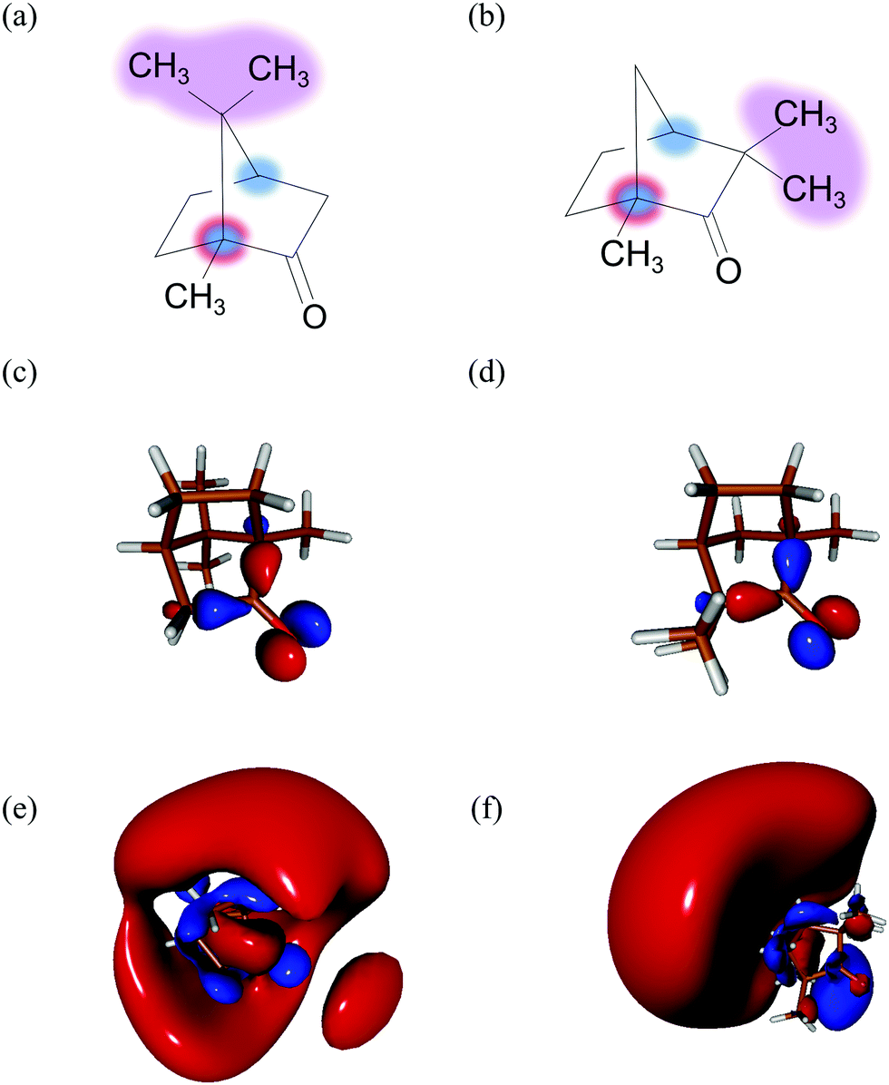 | ||
| Fig. 1 Two monoterpenoid isomers – the most abundant enantiomers in nature: (a) 1R,4R-(+)-camphor and (b) 1R,4S-(−)-fenchone with the 1R chiral carbon labelled in blue/red and 4R/4S in blue. Similarities between the HOMO orbital of camphor (c) and fenchone (d). The orbital 3s of camphor (e) and fenchone (f) populated by the pump pulse. | ||
In the following, we are concerned with an ionization taking place around 9.2 eV, near the ionization energy of camphor (IE = 8.66 ± 0.01 eV25). PECD in static camphor has been studied in the VUV spectral range.7,10 At 9.2 eV, the VUV-PECD of 1R,4R-(+)-camphor ionized by left-polarized light (LCP) has ∼−5% amplitude – the electrons are preferentially emitted in the backward hemisphere. Following the same Cahn–Ingold–Prelog sequence for the first chiral center (in C1), the closest rigid isomer of 1R,4R-(+)-camphor is 1R,4S-(−)-fenchone. The VUV-PECD of the latter reaches ∼+15% at 9.2 eV.7 There is thus a huge isomerism effect in one-photon ionization of fenchone and camphor near the ionization threshold. These two isomers however have very similar Highest Occupied Molecular Orbitals (HOMO, see Fig. 1(c) and (d)) from which the electron is pulled out. Therefore, this isomerism effect recorded in the VUV range stems from different electron scatterings in fenchone and camphor, leading to different final projections of the electron in the molecular continuum. PECD in static camphor has also been observed in a (2 + 1)-REMPI scheme where the two first photons reach the 3s-Rydberg state and one additional photon ionizes the molecule.15,26 The (2 + 1)-REMPI-PECD of 1R,4R-(+)-camphor reverses sign with respect to its VUV counterpart, presenting a ∼+8% amplitude. Such a behaviour is understood as the influence of the intermediate 3s resonance. Conversely, the (2 + 1)-REMPI-PECD of 1R,4S-(−)-fenchone reaches similar values as its VUV counterpart, with an amplitude of ∼+12%.24,26 This comparison raises the question of the role of the intermediate 3s resonance in the PECD, which the present work aims at re-examining in a time-resolved (1 + 1′)-REMPI scheme.
Here, camphor molecules will be promoted to their excited 3s state through the absorption of one pump photon before being ionized by one delayed probe photon of distinct energy. The relaxation dynamics of the 3s-Rydberg state will be observed through the temporal dependence of both the symmetric and asymmetric parts of the photoelectron momentum distribution. Comparison with our previous experiments in fenchone23 will enable us to reveal the sensitivity of relaxation dynamics to isomerism, even if fenchone and camphor are a priori excited to a similar 3s-Rydberg state (see Fig. 1(e) and (f)) with similar anisotropy of excitation and subject also to vibronic relaxations. This will adequately complement the previous static studies.
The paper is structured as follows. In Section 2, we describe the experimental setup based on a Velocity-Map Imaging (VMI) spectrometer and each step involved in extracting TR-PECD from raw VMI-images. In Section 3, we present and discuss the ion and PECD transients for three different polarizations of the pump (S3 = ±1,0), in line with the recent work on limonene27 in which we investigated the influence of the anisotropy of excitation. In Section 4, we introduce the theoretical background used to model the photoelectron angular spectrum and associated PECD in the static (1 + 1′)-REMPI regime. Special attention is paid to the origin of isomerism effects in this interaction scheme by comparing the TR-PECD recorded on 1R,4R-(+)-camphor with the one obtained in 1R,4S-(−)-fenchone. This section also includes a theoretical investigation on how the decay of the anisotropy of excitation impacts the TR-PECD. Finally, we summarize our findings in Section 5.
2 Experimental description
2.1 Experimental setup
The experimental setup consists of a molecular beam chamber with a 1 kHz Even-Lavie pulsed valve, coupled to a velocity-map imaging (VMI) spectrometer and a 26 fs–1 kHz-Ti:sapphire laser system (Aurore facility28 – 800 nm). The enantiomerically pure sample of 1R,4R-(+)-camphor has been provided by Sigma-Aldrich with 98% chemical purity and an optical rotation quoted at α25D = 44.1°. The pulsed valve, with a 250 μm conical nozzle, is used at 80 °C to get a significant vapour pressure and to avoid cluster formation with the minimal 8 bars of helium required to get a stable pulsed molecular beam. Typically this seeded supersonic molecular beam (∼1000 km s−1) generates a rotational temperature on camphor of few tens of kelvin.29,30One part of the laser beam is used to generate the pump pulse at 6.16 eV (201.3 nm) with a 25 meV Full Width Half Maximum (FWHM). With these UV pulse characteristics, the 3s-Rydberg state of camphor is expected to be vibrationally excited with less than 100 meV.31 To photoionize near 9.2 eV, the probe pulse is simply the second harmonic of the fundamental pulse centered at 3.1 eV (λ = 400 nm) with a 100 meV bandwidth. The (1 + 1′) total energy is 600 meV above the IE and 440 meV below the dissociative ionization threshold.7 This excitation scheme is summarized in Fig. 2. The pump and probe beams are focused on the molecular beam with f = 250 mm and f = 600 mm focal lenses, respectively, and crossed with a 4° angle. In order to restrain the excitation scheme to (1 + 1′), the pump (3 μJ p−1) and probe (8 μJ p−1) intensities are maintained quite low at 5 × 10¹¹ and 1 × 10¹¹ W cm−2, respectively. This soft ionization produces only 9% of dissociative ionization events via a (1 + 1′ + 1′)-scheme. The circular polarizations have been obtained by introducing a zeroth order quarter waveplate on the probe beam and a Berek compensator adjusted to a π/4 phase delay on the pump beam. The cross-correlation time as well as the time overlap has not been determined on another molecular compound but extracted from the fit of the transients of the parent ion (C10H16O+). The cross-correlation time is ∼200 fs due to the residual chirp of the UV pump pulse.
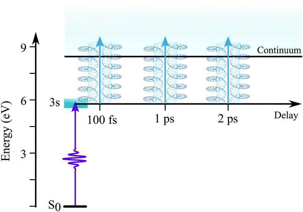 | ||
| Fig. 2 Schematic of the excitation scheme used to measure TR-PECD from the 3s-Rydberg state of camphor. | ||
The photoelectrons have been collected in a direction perpendicular to the plane defined by the laser and molecular beams, and detected at the end of a 40 cm time-of-flight tube using an imaging detector consisting of two micro-channel plates (MCP – 7 cm in diameter) coupled to a phosphor screen (P43) and a 16 bit CCD camera. An energy resolution of 82 meV for photoelectrons at 0.7 eV kinetic energy was determined by photoionizing krypton atoms. The optimisation of ±45° angles relative to the neutral axis of the quarter waveplate of the probe was first done optically with a polarizer, and an accuracy better than one degree was achieved via the optimization of the one-colour PECD images recorded at 400 nm.14 This results in an electron yield of the 1 + (1′-RCP) ionization 0.6% higher than the one associated to 1 + (1′-LCP). This difference that stems from the quarter waveplate limitations was corrected by multiplying each pixel of the images recorded with a left-circularly polarized probe by a factor of 1.006.
Ionization data were recorded by scanning the pump–probe delays typically twenty times: for each probe helicity and at each delay, one pump–probe image was recorded over 51![[thin space (1/6-em)]](https://www.rsc.org/images/entities/char_2009.gif) 000 laser shots. For each scan and due to the commensurability between (1 + 1′) and (2′ + 1′) ionization, two background images corresponding to the probe pulse alone at each helicity were recorded and subtracted from each pump–probe image.
000 laser shots. For each scan and due to the commensurability between (1 + 1′) and (2′ + 1′) ionization, two background images corresponding to the probe pulse alone at each helicity were recorded and subtracted from each pump–probe image.
2.2 Data processing
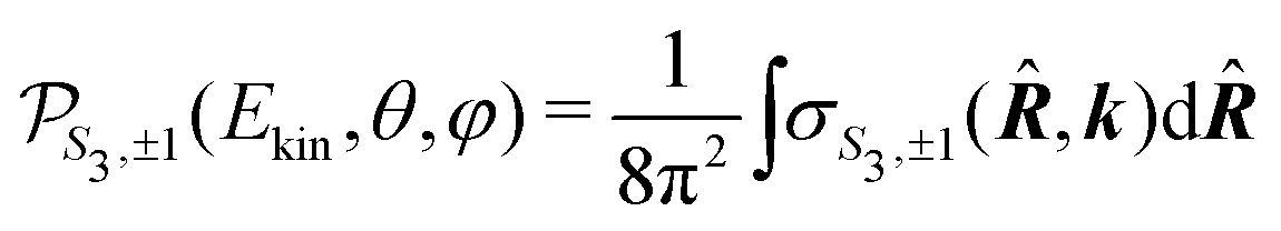
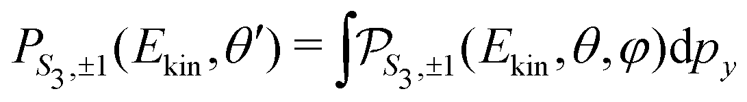
For a given pump–probe delay t, the VMI spectrometer provides 2D photoelectron angular distributions PS3,±1(Ekin,θ′,t) in which the third Stokes parameter S3 defines the amount of circularly polarized photons of the pump pulse, whereas the polarisation state of the probe is equal to ±1 (RCP/LCP). Ekin is the kinetic energy of the photoelectron and θ′ is the polar angle in the VMI detector plane. θ′ = 0 points to the (forward) direction of light propagation while θ′ = 180° points backward. The VMI images are projections of the 3D differential ionization cross sections , where θ and φ are the spherical angles defining the direction of photoelectron ejection. This cross section, resulting from two-photon absorption, can be decomposed as
 | (1) |
 are cosine (m > 0) and sine (m < 0) real spherical harmonics. It can be shown analytically, as in ref 32 and 33, that the asymmetric part of the electron yield is directly related to the coefficients
  with either (
![[small script l]](https://www.rsc.org/images/entities/i_char_e146.gif) odd and m ≥ 0) or ( even and m < 0), while the symmetric part depends on the remaining ones. The coefficient
odd and m ≥ 0) or ( even and m < 0), while the symmetric part depends on the remaining ones. The coefficient  is the TR-PES. We detail in the following the procedure which is implemented to link the 2D PS3,±1(Ekin,θ′,t) and the 3D
  distributions, depending on the polarization state of the pump which can be linear (S3 = 0) or circular (S3 = ±1).
 | (2) |
(cosθ′) are projections of Legendre polynomials onto the VMI plane. The parameters B±1,±1(Ekin,t) with odd reverse sign as the probe helicity changes from +1 to −1, or equivalently, as the enantiomeric nature of the sample changes from (+) to (−) for a fixed helicity. The even parameters are independent of both the probe helicity and the enantiomer. Furthermore, the values of all B±1,±1(Ekin,t) coefficients do not depend on the pump helicity. Therefore, we use the following convention: B(Ekin,t) ≡ B±1,−1(Ekin,t), keeping in mind that B±1,+1(Ekin,t) = (−1)B±1,−1(Ekin,t). The B parameters are related to those entering the definition (1) of the differential cross section by  because of the relationship between 2m = 0 spherical harmonics and Legendre polynomial projections.
The forward/backward symmetric part of (2), S±1(Ekin,θ′,t), is obtained by averaging the VMI signals associated to left-handed and right-handed probe polarizations:
 | (3) |
 | (4) |
 | ||
| Fig. 3 (a) PECD being a normalized quantity, we need to measure the total number of electrons produced for each kinetic energy. This is achieved by the treatment of the symmetric part of the image – SS3(Ekin,θ′,t) – shown here for the 100 fs delay and S3 = 0. (b) The antisymmetric part of raw images – AS3(Ekin,θ′,t) – is post-processed with first a symmetrization relative to the vertical direction contained in the polarization plane (similar to the pump polarisation when S3 = 0), followed by an asymmetric operation relative to the propagation axis as illustrated for the same 100 fs pump–probe delay and S3 = 0. The same contrast sensitivity is used for the raw and the processed images. (c) Fit of the antisymmetric images recorded in 1R,4R-(+)-camphor with a linearly polarized pump (S3 = 0) that shows the quality of the fitting procedure of the images for two different delays despite the 2m = 0 restricted decomposition. | ||
The antisymmetric chirosensitive part of the 2D VMI distribution, A±1(Ekin,θ′,t), is obtained by subtracting the images recorded with opposite probe helicities P±1,−1(Ekin,θ′,t) − P±1,+1(Ekin,θ′,t), which results in
 | (5) |
The set of B(Ekin,t) coefficients are extracted from the symmetric and antisymmetric parts of the experimental images by using the relations (4) and (5). In practice, the symmetric and antisymmetric parts of the experimental images are fitted using the Legendre Polynomial projection basis {P(cosθ′)} with = 0…4. The extracted B are then divided by  in order to get the
  . Using eqn (1), it is then possible to retrieve the 3D photoelectron distribution associated to the experimental projections.
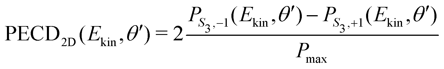
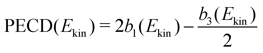
In the present experiment, the ionization yields a single photoelectron peak located at a well fixed kinetic energy such that it is easy to define an angle- and energy-integrated TR-PECD, characterizing the degree of asymmetry of the whole ionization peak, as23
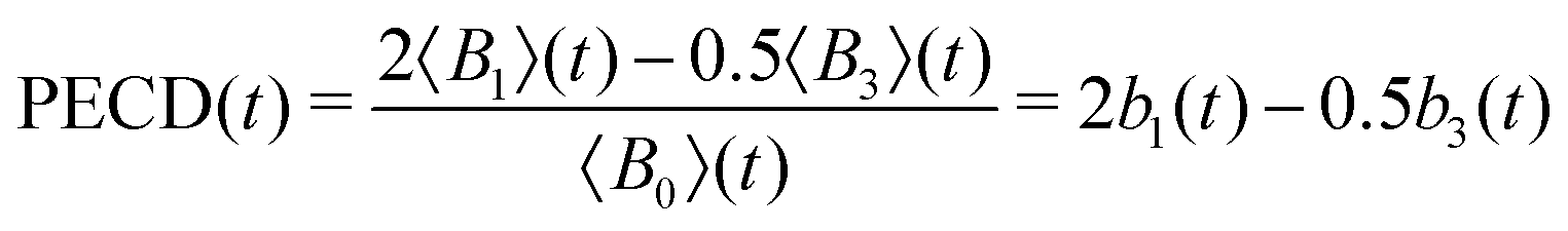 | (6) |
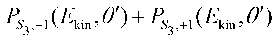
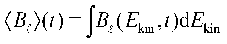 , an integration performed over 130 meV centred at Ekin = 0.5 eV. Note that the difference between the multiplicative factors appearing in front of the coefficient B3(Ekin,t) in eqn (5) and 〈B3〉 (t) in eqn (6) comes from the integration over the spherical angles that allows to pass from the projected representation of the asymmetry to its angularly integrated form.
![[x with combining circumflex]](https://www.rsc.org/images/entities/i_char_0078_0302.gif) , corresponding to a Stokes parameter S3 = 0, the 3D photoelectron momentum distribution does not fulfill cylindrical symmetry anymore. The VMI-projected image in the (,ẑ)-plane is then
, corresponding to a Stokes parameter S3 = 0, the 3D photoelectron momentum distribution does not fulfill cylindrical symmetry anymore. The VMI-projected image in the (,ẑ)-plane is then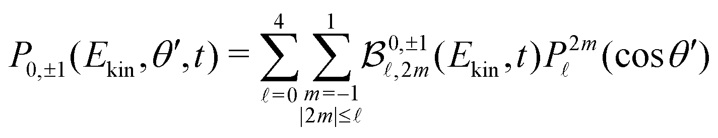 | (7) |
(cosθ′) are projections of the real spherical harmonics introduced in (1). In practice, some of the P2m(cosθ′) projections are linearly dependent, which prevents obtaining a unique set of  parameters for a given t. We circumvent this issue by restricting the decomposition (7) to 2m = 0, yielding
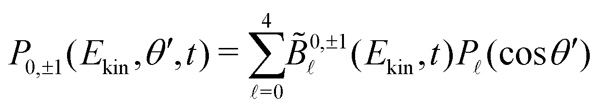 | (8) |
![[B with combining tilde]](https://www.rsc.org/images/entities/i_char_0042_0303.gif) (Ekin,t) = 0,−1(Ekin,t), with 0,+1(Ekin,t) = (−1)0,−1(Ekin,t).
(Ekin,t) = 0,−1(Ekin,t), with 0,+1(Ekin,t) = (−1)0,−1(Ekin,t).
The symmetric and antisymmetric parts of the VMI images are obtained as in the case of a circularly polarized pump (see eqn (4) and (5)),
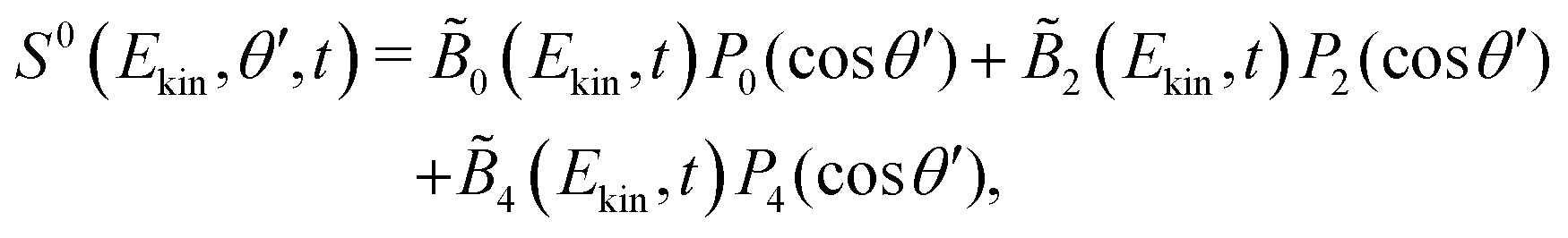 | (9) |
 | (10) |
 coefficients and the experimental projections.
The integrated TR-PECD is defined similarly as before,
 | (11) |
 and
and ![[b with combining tilde]](https://www.rsc.org/images/entities/i_char_0062_0303.gif) 1,3(t) are the quantitative antisymmetric observables, normalized to the total number of photoelectrons. As established in ref. 23, while 1(t) describes the first-order asymmetric response, 3(t) describes the anisotropy of the asymmetric signal, induced by the pump excitation process.
1,3(t) are the quantitative antisymmetric observables, normalized to the total number of photoelectrons. As established in ref. 23, while 1(t) describes the first-order asymmetric response, 3(t) describes the anisotropy of the asymmetric signal, induced by the pump excitation process.
Additionally to the comparisons made in Fig. 3(c), the reliability of the 2m = 0-restricted decomposition (eqn (8)) of the collected signals can be checked at the level of the integrated TR-PECD by comparing the result of eqn (11) with the direct experimental value, to which we refer to as ‘raw’ PECD. The latter is obtained as
 | (12) |
3 Experimental results
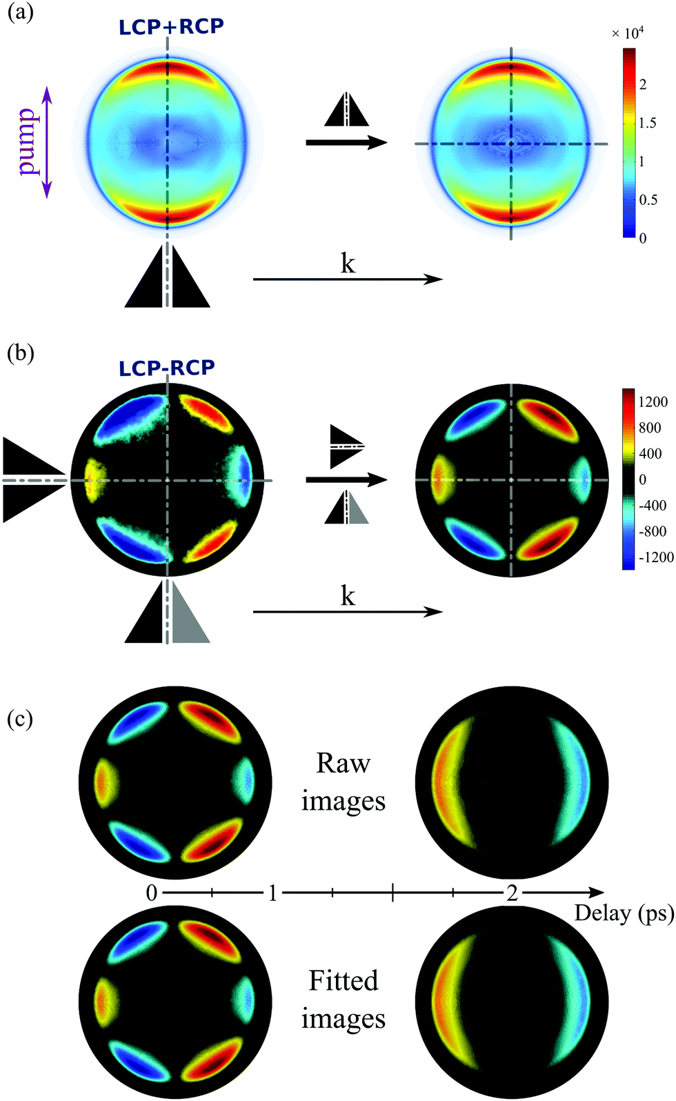
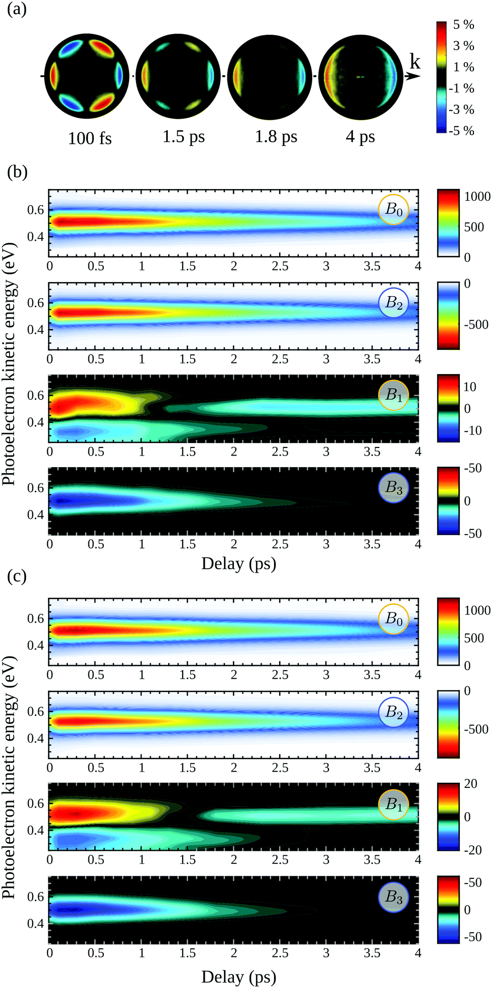
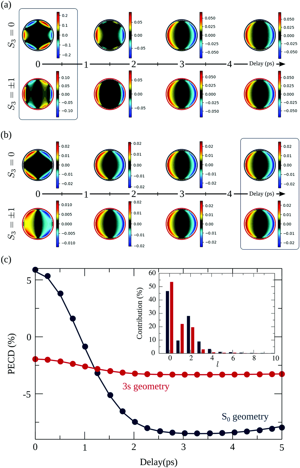
We show in Fig. 4 the asymmetric part A0(Ekin,θ′,t) of the projected photoelectron momentum distributions obtained in (+)-camphor and (−)-fenchone for S3 = 0 and prototypical pump–probe delays t = 0.1, 1 and 2 ps. These asymmetries are nothing else than unnormalized versions of the projected two-dimensional PECDs. Note that the normalized versions will be shown for other typical delays in Fig. 5(a). | ||
Fig. 4 The photoelectron images recorded on (a) 1R,4R-(+)-camphor and (b) 1R,4S-(−)-fenchone for each probe helicity, left-circularly polarized (LCP) and right-circularly polarized probe (RCP), are subtracted one from the other (LCP–RCP) and then processed as explained in Fig. 3 to get the photoelectron forward-backward asymmetric A0(Ekin,θ′,t) images relative to the propagation axis ![[k with combining right harpoon above (vector)]](https://www.rsc.org/images/entities/i_char_006b_20d1.gif) of the laser pulses. Here S3(pump) = 0. These A0(Ekin,θ′,t) images plotted with the same contrast sensitivity show a drastic change as a function of the pump–probe delay: a forward asymmetry of the photoelectron before 1 ps converging to a backward one at longer delays in camphor (a), while fenchone maintains a forward asymmetry whatever the delay (b). of the laser pulses. Here S3(pump) = 0. These A0(Ekin,θ′,t) images plotted with the same contrast sensitivity show a drastic change as a function of the pump–probe delay: a forward asymmetry of the photoelectron before 1 ps converging to a backward one at longer delays in camphor (a), while fenchone maintains a forward asymmetry whatever the delay (b). | ||
 | ||
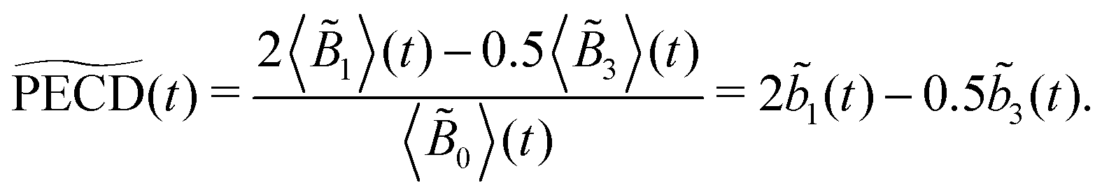
| Fig. 5 TR-PECD in 1R,4R-(+)-camphor with S3(pump) = 0: (a) for each delay t, the previous A0(Ekin,θ′,t) images are now normalized to the maximum of the corresponding S0(Ekin,θ′,t) images; (b) time and energy dependencies of the factors 0(Ekin,t), 2(Ekin,t), 1(Ekin,t) and 3(Ekin,t). | ||
At first glance, Fig. 4 is enough to observe qualitatively large isomeric effects between camphor and fenchone. First, at short delay, the 2D PECD of camphor exhibits a 6-lobe angular structure while its counterpart in fenchone has a fixed sign within the whole forward and backward hemispheres. Second, the angular structure of the PECD is maintained in both isomers between t = 100 fs and t = 1 ps, but the maximal amplitude of the 2D PECD decays faster in camphor than in fenchone. Third, the angular structure of the 2D PECD is lost between t = 1 and t = 2 ps in camphor while it hardly changes in fenchone within the same time interval. Finally, the overall preferential direction of electron ejection, defined as the integrated signal in the backward and forward hemisphere, is reversed between t = 100 fs and t = 2 ps in camphor, while electrons are preferentially emitted in the forward direction at all times in fenchone.
In order to perform a quantitative analysis of the ongoing dynamics, we now employ eqn (9) and (10) to extract from the symmetric S0(Ekin,θ′,t) and antisymmetric A0(Ekin,θ′,t) parts of the VMI signals the i(Ekin,t) coefficients underlying the time-dependent photoelectron distribution in camphor. The same procedure was employed and illustrated in ref. 23 for fenchone. These coefficients are shown in Fig. 5(b). All the coefficients peak about a photoelectron kinetic energy Ekin = 0.5 eV in agreement with the previous (2 + 1)REMPI.14,15 This value is 0.1 eV lower than the one expected from vertical ionization from the 3s Rydberg intermediate state fulfilling the ΔEvib = 0 propensity rule. No salient feature depending on the electron kinetic energy shows up in Fig. 5(b). Indeed, our probe photon energy does not allow one to probe the rising population in the valence states originated from Rydberg-valence vibronic relaxation since these states lie too low on the energy scale. The TR-PES, 0(Ekin,t), thus illustrates the monotonous decrease of the 3s-state population. 2(Ekin,t) corresponds to the anisotropy of symmetric differential electron ejection and remains significant as long as the 3s state is significantly populated, i.e. up to t ∼ 7 ps. The higher-order anisotropy 4(Ekin,t), resulting from two-photon ionization, is very small (with a maximum of amplitude less than 1/7 of 2(Ekin,t)) throughout the interaction. Accordingly, it is not displayed in Fig. 5(b). The analysis of the time-resolved symmetric photoelectron signal does not finally provide further information than the (expected) relaxation of the intermediate 3s state. Our previous study on TR-PECD in fenchone23 led to the same conclusion.
We thus turn to the time-resolved antisymmetric part of VMI signals and the associated 1(Ekin,t) and 3(Ekin,t) Legendre coefficients. In fenchone,23 we found that 3(Ekin,t) < 1(Ekin,t) for all pump–probe delays t, which explains the shape of the 2D PECD that looks like the Legendre polynomial P1(cos(θ′)) (see Fig. 4(b)). Moreover, the asymmetry, mainly dictated by 1(Ekin,t) in that case, was found to stay forward for all pump–probe delays. In contrast, Fig. 5(b) shows that in camphor, the absolute value of 3(Ekin,t) is stronger than that of 1(Ekin,t) at short delays. The anisotropy of the asymmetry, rationalized by 3(Ekin,t), is thus important in camphor at small t, yielding the 6-lobe angular structure observed in the 2D PECD of Fig. 4(a) and 5(a). This strong anisotropy of A0(Ekin,θ′,t) observed at small delay is the first isomeric effect revealed by the TR-PECDs of fenchone and camphor, consistently with the raw data shown in Fig. 4.
The main other difference between the two isomers is the sign reversal of 1(Ekin,t) in camphor at long delay. This sign switch appears around 1.2 ps and is concomitant with 3(Ekin,t) converging to zero (see Fig. 5(b)). This results in a TR-PECD which rapidly loses its angular structure and reverses the preferential direction of the electron to become backward as previously observed in Fig. 4(a) and 5(a).
In order to quantitatively extract the characteristic timescales of the dynamics, we now turn our attention to the time-dependencies of the photoelectron yield 〈0〉 (t) and normalized asymmetric coefficients 1(t) and 3(t) entering the definition (11) of  . These transients, shown in Fig. 6(a), have mono-exponential time-dependencies that can be fitted as
 | (13) |
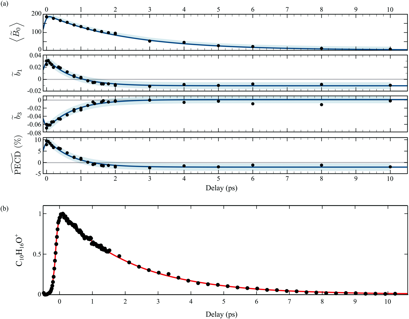 | ||
Fig. 6 (a) Time dependencies of the factors 0(Ekin,t), 1(t) and 3(t). The  percentage is then calculated by using eqn (11). The light blue areas correspond to the 50% confidence bounds of the fits using eqn (13). (b) Time-dependencies measured on the parent ion, which are normalised raw data without background subtraction on the contrary to the photoelectron images. percentage is then calculated by using eqn (11). The light blue areas correspond to the 50% confidence bounds of the fits using eqn (13). (b) Time-dependencies measured on the parent ion, which are normalised raw data without background subtraction on the contrary to the photoelectron images. | ||
Table 1 summarizes all the decay times τ and the asymptotic values extracted from the time-transients, as well as their counterparts for fenchone.23 In the case where the 3s-Rydberg state is populated through the interaction with a linearly polarized pump (S3 = 0), the decay time measured for the parent cation is τ(C10H160+) = 2.2 ps while the photoelectron signal 〈0〉 (t) decays within 2.36 ps. These decay times coincide, as expected for non-dissociative ionization, and characterize the timescale of vibronic relaxation of the 3s-Rydberg state into the valence states. As shown in Table 1, the 3s state relaxation is 25% slower in fenchone than in camphor. This is counterintuitive since the pump deposits more vibrational energy in the 3s state of fenchone than in camphor – 250 vs. 90 meV, according to the band origins of the 3s state in the respective isomers.15,20 Therefore, our results show that internal conversion is sensitive to isomerism through the intricate and different vibrational dynamics taking place in the transient electronic state.
| Observables | 1R,4R-(+)-Camphor – present work | 1R,4S-(−)-Fenchone23 | ||||||
|---|---|---|---|---|---|---|---|---|
| Decay (ps) | Converging value | Decay (ps) | Converging value | |||||
| S 3 = 0 | S 3 = −1 | S 3 = 1 | S 3 = 0 | S 3 = −1 | S 3 = 1 | S 3 = 0 | ||
| C10H16O+(t) | 2.20 ± 0.05 | 3.18 ± 0.04 | ||||||
|
0(t) or B0(t) (PES) |
2.36 ± 0.07 | 2.65 ± 0.25 | 2.60 ± 0.29 | 3.28 ± 0.05 | ||||
|
1(t) or b1(t) |
0.75 ± 0.05 | 2.07 ± 0.25 | 2.30 ± 0.18 | −0.01 | −0.02 | −0.02 | 3.25 ± 0.5 | 0.073 |
|
3(t) or b3(t) |
0.77 ± 0.04 | 1.28 ± 0.22 | 1.28 ± 0.20 | 0 | 0 | 0 | 1.4 ± 0.3 | 0 |
 or PECD(t) or PECD(t) |
0.73 ± 0.05 | 1.94 ± 0.19 | 2.10 ± 0.14 | −1.94% | −4.2% | −5% | 3.25 ± 0.5 | +14.6% |
| PECDr(t) | 0.84 ± 0.07 | 1.91 ± 0.40 | 2.05 ± 0.40 | −1.36% | −3% | −3.6% | ||
A larger, and totally unexpected, isomerism effect shows up in Table 1 as one compares the decay times of  in fenchone and camphor. In fenchone,
  , which roughly corresponds to the 3s relaxation time. This means that the chiral asymmetry is encoded in the photoelectron yield almost as long as the intermediate 3s state is populated. The anisotropy of the asymmetry in fenchone, measured by 3, was found to decay faster (τ(3) = 1.4 ps) as expected by the rotational dephasing of the molecules due to a non-zero rotational temperature of fenchone.23 But in camphor,
  decays much faster than the 3s state relaxes: the time constants associated to 〈0〉 and
  are ∼2.4 ps and ∼0.7 ps, respectively. This means that the chiral photoelectron asymmetry has converged to a finite value long before the population of the transient 3s state, and subsequent ionization, vanish. This result could be artificial and due to the inadequacy of our analysis of the experimental images, based on the 2m = 0-restricted decomposition of the photoelectron signal – even if the reliability of this decomposition has been checked and presented in Fig. 3(c). Therefore, we directly evaluated the raw PECD according to eqn (12), and extracted both its decay time and asymptotic value. The agreement of raw and computed PECD, presented in Table 1, is reasonable and proves that the rapid loss of chiral asymmetry in (1 + 1′)-ionization of camphor is not artificially introduced by our 2m = 0-restriction. This faster decay could be rather due to fast internal vibrational relaxation (IVR), populating vibrational modes with inherent opposite PECDs and whose superposition leads to a vanishing net asymmetry.12 In this respect, we observed such a fast IVR in fenchone:23 the TR-PECD was found to decrease within ∼400 fs before increasing smoothly on a ps timescale, towards its asymptotic value. We assigned this first 400 fs to a fast IVR, populating vibrational modes active in the internal conversion (IC) from 3s state to the valence ones but with opposite PECDs, while the subsequent ps increase of the net PECD was related to long-lived vibrational spectator modes of this same IC. In camphor, the TR-PECD continuously decreases from t = 0 onwards so that IVR and vibrationally selective internal conversion cannot be differentiated as easily as in fenchone. While the decrease of the PECD at small t can be safely ascribed to IVR, its subsequent evolution is monitored by both the vibrationally selective internal conversion and the loss of anisotropy of molecular orientations.
In order to gauge the influence of transient vibrational dynamics in the fast decay of PECD in camphor, we performed TR-PECD measurements with a circularly polarized pump (S3 = ±1). Indeed, changing the pump polarisation state from S3 = 0 to S3 = ±1 does not modify the vibrational excitation, which means that any time dependencies related to IVR should be the same. Normalized A+1(Ekin,θ′,t) images, for a few delays, are presented in Fig. 7(a), while the associated temporal evolution of B0–3(Ekin,t) for S3 = ±1, are displayed in Fig. 7(b) and (c). The decay constants of B0–3(Ekin,t) and PECD(t), as well as their asymptotic values, are listed in Table 1. Within the error bars, the dynamics recorded through both symmetric (〈B0〉(t)) and asymmetric (b1,3(t) and PECD(t)) observables do not depend on the helicity of the pump pulse. This is consistent with the fact that the 3s-state population, resulting from pump-induced sudden excitation, is identical for S3(pump) = 1 and for S3(pump) = −1. The time constant associated to 3s-state internal conversion is τ(B0) = (2.6 ± 0.25) ps for S3 = ±1 while it is ∼(2.36 ± 0.07) ps for S3 = 0: the 3s state relaxes within the same timescale whatever S3. However, while we observed that τ(b1) ≪ τ(B0) for S3 = 0, we now recover the intuitive result τ(b1) ∼ τ(B0) observed in fenchone:23 chirality survives throughout electron emission from the damped (relaxing) 3s state. We further observe that τ(b3) < τ(b1) with τ(b3) ∼ 1.3 ps. As in fenchone,23 the latter timescale can be assigned once again to rotational dephasing since camphor has similar moments of inertia. We will come back to this loss of anisotropy of excitation further. Finally, the angle-integrated PECD, mainly monitored by b1, evolves with τ(PECD) ∼ τ(B0). This comparison of S3(pump) = 0 and ±1 reveals a strong pump-polarization dependence of the temporal evolution of the PECD in camphor and is the signature of an effect beyond a pure vibrational dynamics.
 | ||
| Fig. 7 TR-PECD in 1R,4R-(+)-camphor with S3(pump) = ±1: (a) for each delay t, A+1(Ekin,θ′,t) images are now normalized to the maximum of the corresponding S+1(Ekin,θ′,t) images. Time and energy dependencies of the coefficients B0, B2, B1 and B3 extracted from the symmetric and anti-symmetric images recorded with a circularly polarized pump: (b) S3 = −1 and (c) S3 = +1. | ||
The pump ellipticity induces a selective response of the molecules randomly oriented within the sample. Only molecules with an excitation dipole aligned along the polarization of the pump will be efficiently excited, and subsequently ionized. For S3 = 0, this results in an effective conical alignment along the linear polarization while for S3 = ±1, this leads to an effective planar alignment in the polarization plane. The PECD is known to depend significantly on this effective alignment,27 and one expects that its value increases for the strongest alignment. We indeed observe in Table 2 that S3 = 0 yields a higher value of PECD than S3 = ±1 does at short delays. The present values are similar to the ones reported in previous experiments14,15,26 using one-color (2 + 1)-REMPI ionization schemes. In these experiments, the first two photons are circularly polarized and allow the intermediate 3s state to be reached as in the present study. It should be further noted that the 2D PECD images resulting from the (2 + 1)-experiments are very similar to the ones presented here at t = 0 in (1 + 1′). This similarity indicates that the molecular orientations selected by the absorption of two circularly polarized photons look like those selected by the absorption of one linearly polarized photon. The latter statement is confirmed by similar b2 and negligible b4 contributions reported in (2 + 1) REMPI experiments.26 As time elapses between excitation and ionization, the rotational distribution of the molecules within the sample tends to be uniform and the influence of pump-induced initial alignment should vanish asymptotically – this is the rotational dephasing effect that can be monitored only in a pump–probe scheme.35 However, we observe in Table 2 and Fig. 8 a noticeable difference at 4 ps between the PECDs with S3 = 0 and S3 = ±1. Here again, there is something beyond, or entangled with, rotational dephasing which tailors the temporal evolution of PECD.
 of camphor at a total energy of photoionization around 9.3 eV and analysed for the unique component of the PES at 0.60 ± 0.06 eV. The two last columns are for the chiral isomer fenchone for similar ionization23
| References | 1R,4R-(+)-Camphor | 1R,4S-(−)-Fenchone | ||||||
|---|---|---|---|---|---|---|---|---|
| 14 | 15 | 26 | 7 | This work at 100 fs | >4 ps | At 100 fs | >5 ps | |
| Ionization scheme | (2 + 1) | (2 + 1) | (2 + 1) | VUV | (1[S3 = 0/±1] + 1′) | (1[S3 = 0/±1] + 1′) | (1 + 1′) | |
| b 1 | +0.025 | +0.028 | +0.026 | − 0.026 |
1 = +0.03/0.014 |
−0.01/−0.015 | +0.057 | +0.07 |
| b 3 | −0.045 | −0.048 | −0.053 | 0 |
3 = −0.06/−0.05 |
0/0 | +0.025 | 0 |
| PECD | +7.25% | +8% | +8% | −5.2% |

|
−1.94/−2.9% | +10% | 14% |
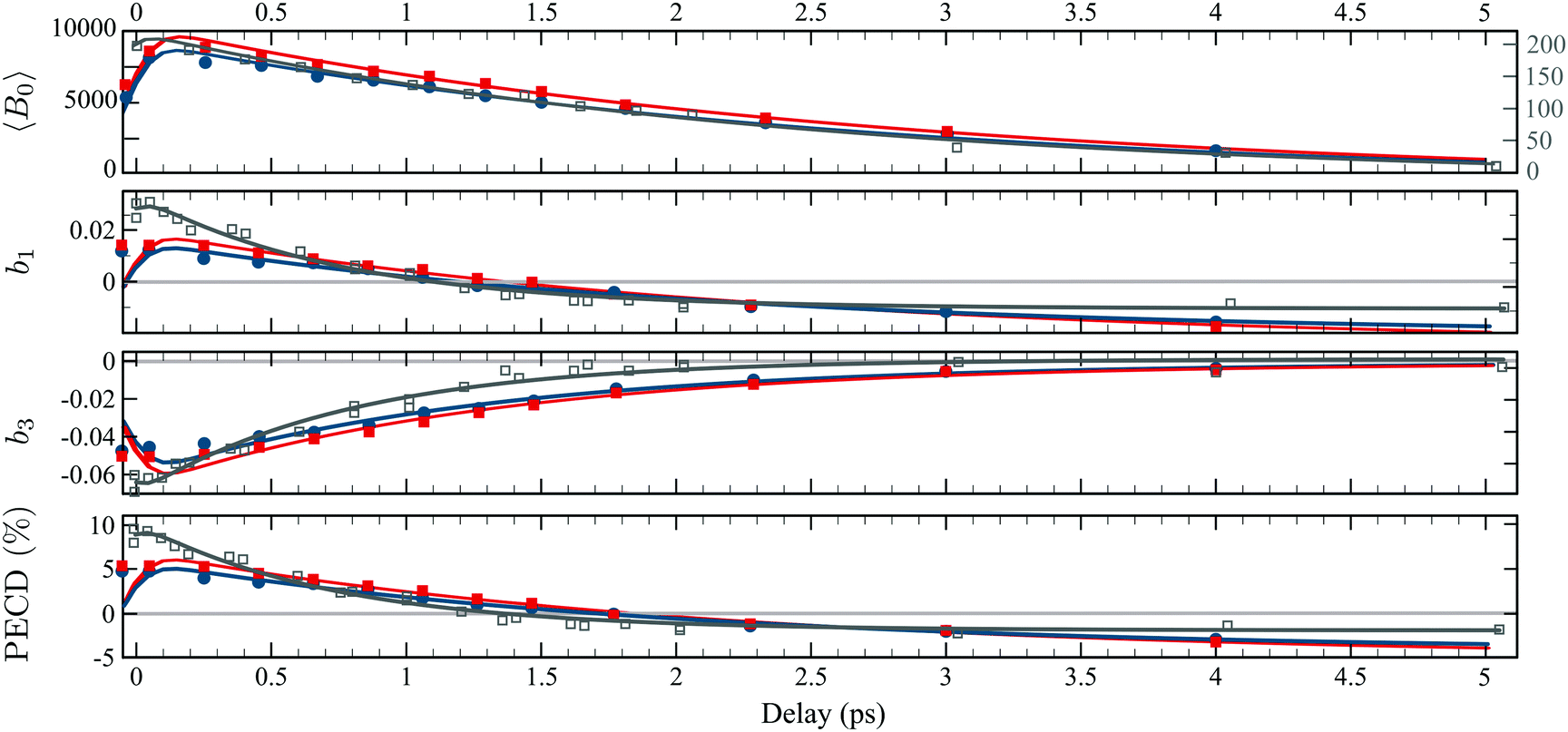 | ||
| Fig. 8 TR-PECD recorded with a circularly polarized pump pulse with S3 = −1 (blue) and with S3 = 1 (red). The decay times as well as the converging values are listed in Table 1. The data and fit in grey are the ones recorded with a linearly polarized pump from Fig. 6(a). | ||
The analysis of the experimental results raises several fundamental questions. What is the origin of the isomerism effect in PECD at short delay? How can we understand the dependence of PECD decay on the pump polarization state in camphor? Does the underlying mechanism involve the interplay between internal (vibrational) and external (rotational) degrees of freedom, and how can it be extrapolated to the understanding of the isomerism effect observed in the time evolutions of PECD in fenchone and camphor?
4 Model and discussion
Atomic units will be used throughout this section unless otherwise stated.4.1 PECD and isomerism effect at short delays
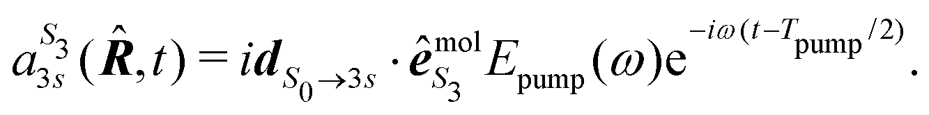
We present in this section the calculations we performed to understand the origin of the isomerism effect observed in the angular PECD of fenchone and camphor at short delays. In the framework of (1 + 1′)-REMPI ionization, we consider non-overlapping pump and probe pulses of respective durations Tpump and Tprobe and delayed by τ. Time t is referenced with respect to the time where the pump field maximizes. We restrict our description of the interaction to a (short) time range within which the nuclear structure of the molecules is assumed to remain frozen. Furthermore, we assume that the pump-induced excitation and the probe-induced ionization, both of which consist of absorption of one photon, are sudden processes which can be described within the Franck–Condon approximation. Vibrational dynamics can then be factored out from the transition amplitudes – they are described in terms of Franck–Condon factors which do not need to be taken into account explicitly when only relative quantities such as PECD are computed.36The photon absorption from low energy pulses can be fairly described by first-order perturbation theory. The pump pulse, with ellipticity S3, promotes the electron from the S0 ground state to the 3s state whose population amplitude at time t ≥ Tpump/2 is, for a molecular orientation ![[R with combining circumflex]](https://www.rsc.org/images/entities/b_i_char_0052_0302.gif) in the laboratory frame:
in the laboratory frame:
 | (14) |
 is the polarization unit vector of the pump, êS3, passively rotated into the molecular frame through
 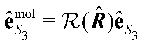 , where
  is a rotation matrix acting on the usual Euler angles (α,β,γ) which defines the molecular orientation in the laboratory frame.43
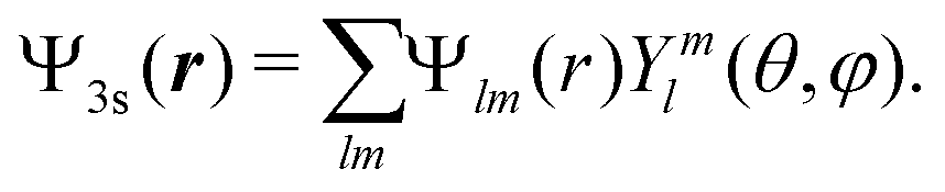
A probe photon is subsequently absorbed and ionizes the molecule from the 3s excited state. The population amplitude of a continuum state defined by a wavevector kmol in the molecular frame is then, for t ≥ τ + Tprobe/2:
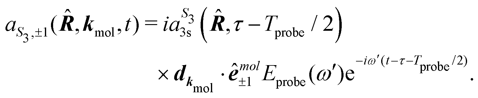 | (15) |
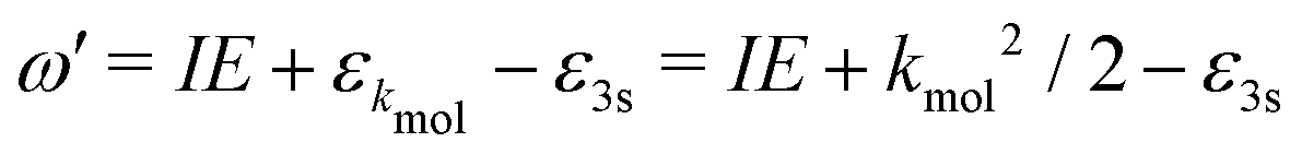 . dkmol is the ionization dipole linking the exited state Ψ3s to the ingoing continuum state
  and
and 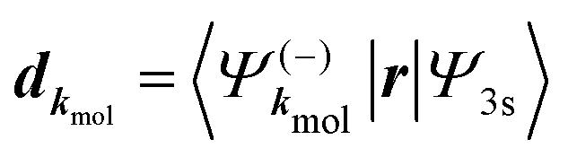 . The differential ionization cross section is directly proportional to the square modulus of the ionization amplitude. It is then clear from eqn (14) and (15) that this cross section does not depend on the time delay t. Then, in a (1 + 1′)-REMPI scheme involving only one intermediate state, the ionization cross section is stationary within the assumptions we made: Franck–Condon approximation and related frozen nuclear geometry for electronic transitions. Therefore, the expression of the ionization amplitude can be simplified by omitting all time-dependent factors, yielding
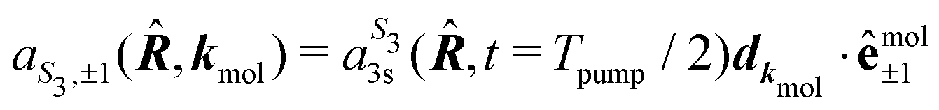 | (16) |
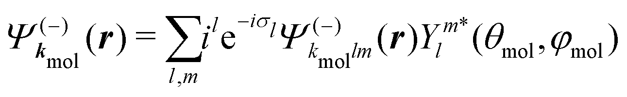 | (17) |
 are spherical complex states, fulfilling ingoing boundary conditions. Consistent with the partial-wave decomposition (17) of
  into spherical harmonics, the rotation of the unit polarization vector ê±1 in the molecular frame is expressed in the spherical basis {êν}ν=−1,0,1 where the rotation matrix
  reduces to its Wigner
  -form,45e.g.
 . Inserting (17) into (16), one thus obtains
 | (18) |
 are the partial-wave ionization amplitudes.
For a given molecular orientation, the cross section in the molecular frame is then
 | (19) |
 is the population of the 3s state at the end of the pump pulse whose ellipticity is defined by the Stokes parameter S3. In the lab frame, the electron ejection is defined by k = (k,θ,φ) with k = kmol. We thus apply a rotation from the molecular to the lab frame to obtain the differential cross section in the latter:
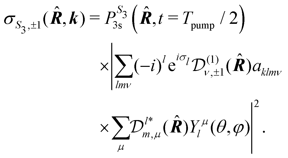 | (20) |
The target sample consists of a set of randomly oriented molecules. The average cross section associated to the whole sample is thus
 | (21) |
 -uniformly distributed orientations i = (αi,βi,γi), with
 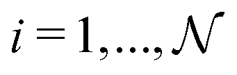 , and Euler angular spacing Δα = Δβ = Δγ = π/24. Then,
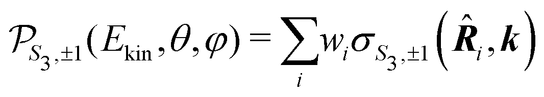 | (22) |
Once the 3D cross section has been computed, we simulate the 2D distributions collected on the VMI plane by integrating  along the TOF-dimension y perpendicular to the detector plane:
 | (23) |
 | (24) |
 along θ′ for a given kinetic electron energy Ekin. Using eqn (1), only enantio-selective terms appear in the expression of the 2D PECD:
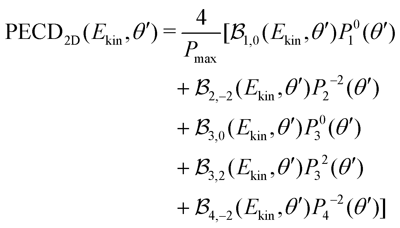 | (25) |
2m(θ′) are projections of the real spherical harmonics Y2m(θ,φ) onto the VMI detector plane (see eqn (7)) and  to shorten the notation. The total, angularly integrated, PECD is defined as
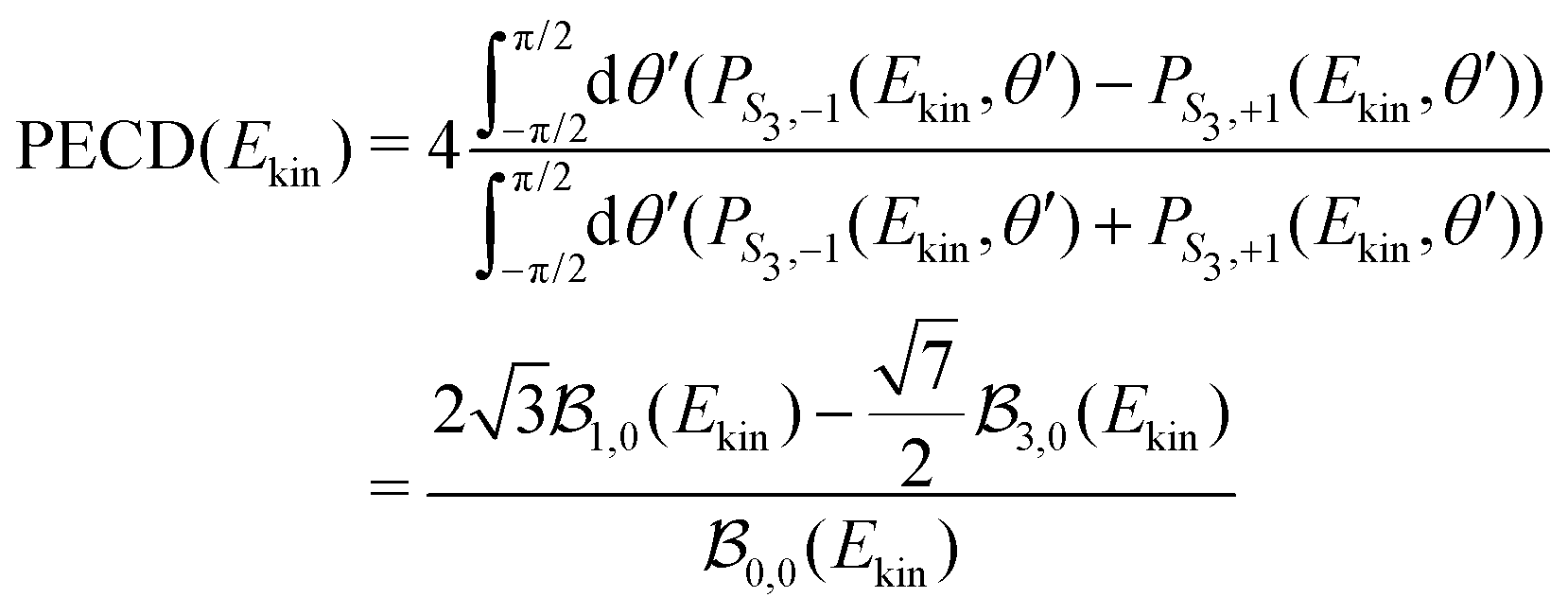 | (26) |
 | (27) |
 and
and  . Note that all coefficients
  with 2m ≠ 0 vanish in the expression of the angularly integrated PECD since
  for 2m ≠ 0.
Calculations have been run for (+)-camphor and (−)-fenchone, considering that (1 + 1′)-REMPI yields in both cases a photoelectron signal centred about Ekin = 0.5 eV, as in the experiments. In practice, the spherical ingoing states  , involved in the computation of akmollmν, are decomposed into real states ψkmollm(r) which are obtained by diagonalizing the coupled-channel (multi-scattering) Schrödinger equation
  . H0 is the unperturbed Hamiltonian. In the TDDFT framework, the excited state Ψ3s only results from one-electron excitations from the HOMO to virtual orbitals. Therefore, we assume that the ionic core also remains frozen during the transition from 3s to the continuum. Accordingly, H0 is an effective one-electron Hamiltonian which can be decomposed as
  where V is the effective potential of the ionic core on the ejected electron. We employ an approximate description of this potential, in terms of the so-called ElectroStatic Potential (ESP) charges46 which basically consist of non-integer charges Zeffi located on the nuclei of the molecule. The effective charges are determined to fit the genuine potential on van der Waals surfaces surrounding the atoms in the molecule according to
 | (28) |
The computed 2D PECD with S3(pump) = 0 is shown in Fig. 9(a) and (b), respectively. The angular structure of the 2D PECD associated to camphor is in excellent agreement with its experimental counterpart, displayed in Fig. 4(a). Six lobes of alternating sign are appearing along the photoelectron ring, which illustrates the importance of anisotropic effects in the chiral asymmetric part of the 3D differential cross section. These effects are quantified by the ratio 3/1 which is equal to −2 (see Table 2). The excellent agreement found in camphor slightly deteriorates for fenchone. Even if the computed 2D PECD (shown in Fig. 9(b)) exhibits a positive sign in the whole forward hemisphere, as in the experiment displayed in Fig. 4(b), the computed PECD distribution is angularly more structured. In fenchone, at the opposite of camphor, the anisotropic part of chiral asymmetry (b3) is thus considerably weaker than its isotropic part (b1) in both calculations and experiments, but the isotropic/anisotropic relative sign is reversed. Indeed while b3/b1 = −0.45 in the calculations, 3/1 = + 0.44 in the experiments. The computed values of the angularly integrated PECDs shown in Fig. 9 are + 5.7% and + 5.6% in (+)-camphor and (−)-fenchone, respectively. They are in reasonable agreement with the measurements that yield + 9% and + 10% for the two respective isomers. In the following, we rely on this experimental/theoretical agreement of 2D PECDs to track the origin of the isomeric effect observed between fenchone and camphor.
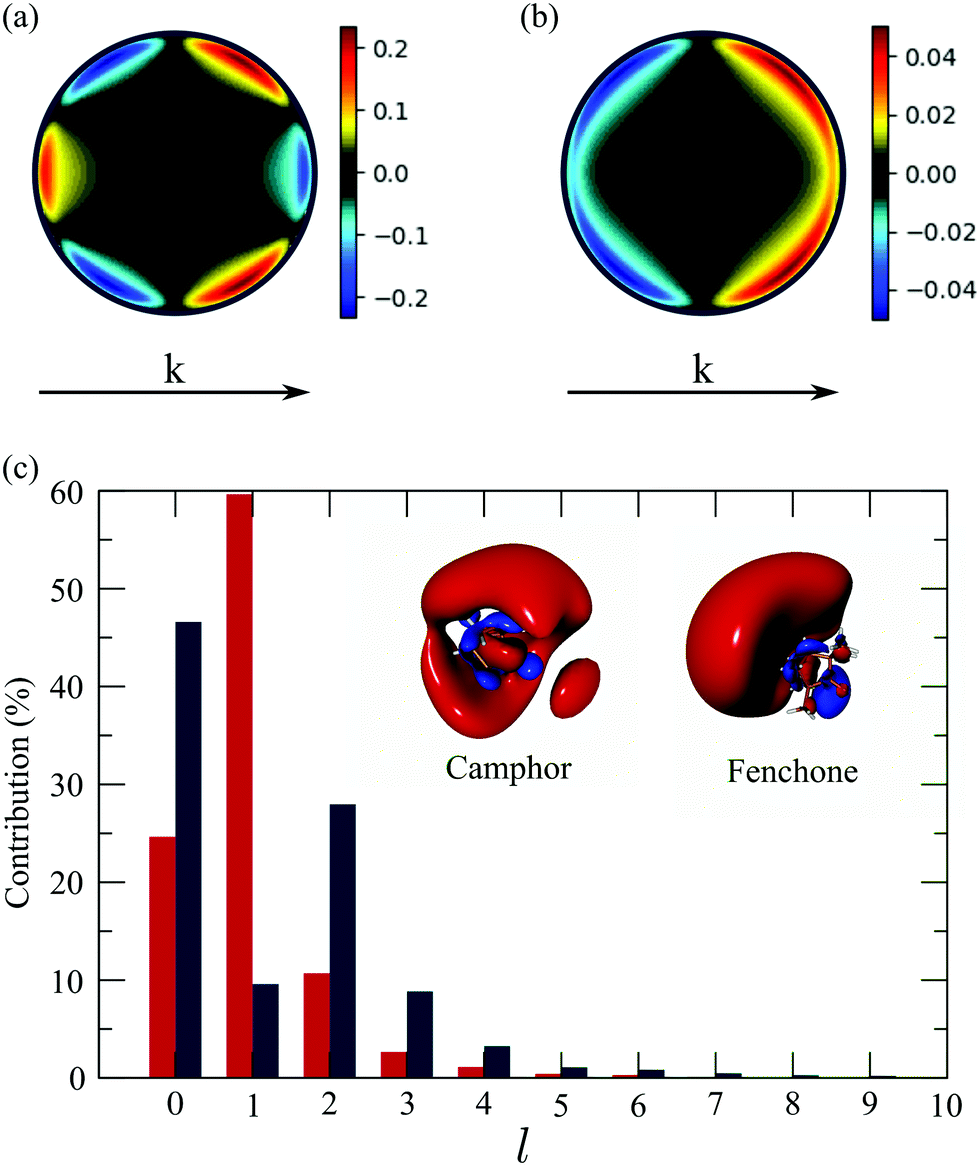 | ||
| Fig. 9 Theoretical angular PECD at t = 0 in (a) camphor and (b) fenchone. (c) Decomposition of 3s-Rydberg state orbitals for camphor (blue) and fenchone (red) as a function of l number at t = 0. | ||
The 3D photoelectron angular distribution depends on three factors: (i) the anisotropy of the molecular spatial distribution induced by the polarization of the pump in the primary excitation process, (ii) the shape of the excited state orbital as the initial condition of the ionization process, and (iii) the structure of the chiral continuum reached during ionization. As outlined above, the chiral continuum is described in terms of ESP charges which are obviously different in fenchone and camphor. However, we ran some simulations where the continuum was described in terms of hydrogenic wavefunctions in both isomers. These simulations have yielded 2D PECDs in qualitative agreement with those of Fig. 9(a) and (b), still exhibiting very different angular shapes in both isomers. This indicates that the structure of the continuum (iii) is not primarily responsible for the isomeric effect. In our simulations, both camphor and fenchone molecules are oriented such that the 3s←S0 excitation dipole lies along the ẑmol direction in the molecular frame. The pump, linearly polarized along in the laboratory frame, thus leads to the same effective conical alignment about , so that (i) can be ruled out as the single source of the isomeric effect. However, the dynamical alignment also determines the preferential orientation of the intermediate 3s state as the initial condition of the ionization process. The influence of the shape of the excited state orbital, whose orientation in the lab frame is determined at the end of excitation, should thus mainly explain the isomerism effect. In this respect, the isomeric effect observed in usual one-photon XUV ionization experiments7 is explained in terms of isomer-dependent scattering of the escaping electron in the chiral potential. Here this effect is strongly lowered since ionization occurs from a Rydberg orbital whose diffuseness limits interaction with the core chirality.
The excited state is directly involved in the definition of the partial-wave ionization amplitudes 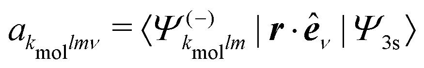 . These amplitudes are calculated employing a partial-wave expansion of the excited state:
 | (29) |
 because of the usual dipolar selection rules inherent to the r·êν operator. The angular momentum l′ in the continuum controls the amplitude of the
  coefficients determining the differential cross section (2) since |l′ − l′′| ≤ ≤ l′ + l′′, where l′ and l′′ are here both continuum momenta. Therefore, an excited state whose partial-wave decomposition mainly consists of one l-contribution will lead to a small
  coefficient while extended l-excited states are amenable to large anisotropy coefficients. We estimate the l-contribution to the (normalized) 3s excited state as
 | (30) |
 coefficient and related exacerbated anisotropy in the former isomer. We thus answer the first question raised in Section 3: in our (1 + 1′)-REMPI scheme, isomeric effects at short delays are mainly due to the shape of the intermediate excited state.
4.2 TR-PECD and rotational dephasing at long delays
We now turn our attention to the time evolution of PECD in camphor, with the aim to understand the mechanisms responsible for the difference in the PECD decay observed for S3 = 0 and S3 = ±1. We also aim at understanding why the PECD switches sign around t ∼ 1–2 ps.Taking into account the ps timescale involved here, we drew from our description of PECD at short delays in the S0 equilibrium geometry and introduced in our model rotational dephasing effects coupled to the effective alignment created by the pump within the randomly oriented sample. Rotational dephasing consists in describing the temporal evolution of the molecular orientation, (t), consistent with the temperature of the molecular sample. Here, rotational dephasing is described classically, as in ref. 47 and 48. At the end of the pump pulse, the molecular orientation (Tpump/2) = (α(Tpump/2),β(Tpump/2),γ(Tpump/2)) is converted to the quaternion representation {qi}, with i = 1,…4.43 Rotational dynamics is then completely described in the representation in terms of the seven differential equations:
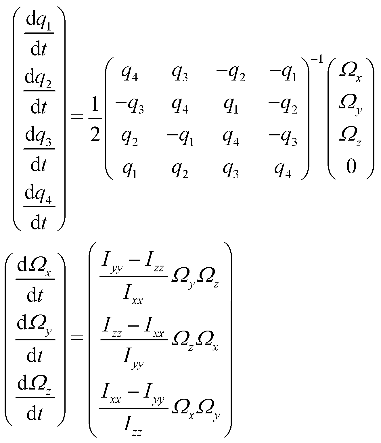 | (31) |
 (with
(with  ) orientations weighted by the transition amplitude
  (see eqn (14)). For each weighted trajectory, several hundred velocities Ωi (Nv = 500) are chosen randomly to form a normal distribution centered around
  , where T is the rotational temperature and Iii is the moment of inertia associated to the principal axis i. In camphor, Ix,y,z = 1241, 1521 and 1639 amu Bohr2 for the S0 ground state equilibrium geometry. The set of
  weighted trajectories is propagated according to eqn (31) until t = 5 ps. At a given delay t, the
  molecular orientations are extracted and quaternions are converted back to Euler angles j(t) = (αj(t),βj(t),γj(t)) with
  . Ionization then occurs, and the differential cross section, averaged on the
  orientations, is defined as
 | (32) |
 | (33) |
Importantly, we still do not account for vibrational dynamics – the molecules remain frozen at their S0 equilibrium geometry. In order to reduce the computational cost, the rotational temperature has been set to 100 K in our simulations, which overestimates the experimental one (∼10–30 K). However, as shown in previous studies,49 this is not problematic and provides an appropriate illustration of the impact of the rotational dephasing on the PECD. In summary, at lower rotational temperature T, all the features described below will occur but with longer time constants.
The temporal evolution of the 2D PECD is shown in Fig. 10(a) for S3(pump) = 0. We observe that the angular structure of the PECD, linked to a strong negative B3,0, changes drastically at t ∼ 1.5 ps and vanishes for t > 3 ps. Asymptotically, all but  coefficients are zero in the expression of the differential cross section. This is fully consistent with the fact that at 3 ps, the distribution of molecular orientations is uniform. Therefore ionization occurs from a randomly oriented 3s-state, yielding a PECD shape similar to the well-known one-photon ionisation (VUV-PECD restricted to b1). Fig. 10(a) also includes the simulated images for S3 = ±1. We observe then that the loss of PECD angular structuring decreases faster in that case, with the 6-lobe patterns hardly visible for t ≳ 1 ps. In conclusion, the effective molecular alignment does not impact identically a PECD undergoing a rotational dephasing. However, this sensitivity vanishes as time elapses beyond ∼3 ps resulting in 2D-PECD images almost identical for S3 = 0 and S3 = ±1.
 | ||
| Fig. 10 Theoretical study of the influence of rotational dephasing in camphor on (a) the 2D-PECD calculated in the S0 ground state geometry for different pump polarization and as a function of the pump–probe delay. (b) Same calculations but in the equilibrium geometry of the 3s Rydberg state. (c) Evolution of angularly integrated TR-PECD, in percent, as a function of the delay for linear (line) and circular (dots) pump polarization for molecules in the S0 ground state equilibrium geometry (blue) and molecules in the 3s Rydberg state geometry (red). In the inset is given the 3s-Rydberg orbital l-decomposition for the S0 ground state equilibrium geometry (blue) and 3s equilibrium geometry (red). | ||
We present in Fig. 10(c) the angularly integrated TR-PECD of these images for S3 = 0 (line) and S3 = ±1 (dots). The PECD reverses sign about t ∼ 1 ps. This is quite consistent with our experiments where such a sign switch has been also observed (see Table 2). However, while the magnitude of the computed PECDs is in reasonable agreement with the experiments at t = 0, the calculations overestimate it at long delays (∼−7.5% vs. ∼−2%). An immediate explanation for such a discrepancy could be that our model neglects some dynamics such as the ongoing vibrational relaxation converging to the 3s-state equilibrium geometry. To partially take into account such geometry change, we implemented calculations where the ionization amplitudes and the moment of inertia were computed at the 3s-state equilibrium geometry. The results are shown in Fig. 10(b) and (c). Despite the little changes between the S0 and 3s equilibrium geometries – less than 3% of internuclear distances – the shape of the 3s state is significantly altered between these two nuclear configurations. This has a drastic impact on the 2D PECDs visible by comparing Fig. 10(a) and (b) at t = 0, for both S3 = 0 and S3 = ±1. For instance, in the 3s geometry, the photoelectron asymmetries are backward whatever the delay. We also note that the loss of PECD angular structuring takes place on a shorter timescale compared to S0 geometry: the final (b1) shape is reached as soon as t ∼ 1.5 ps. In conclusion, not only the effective molecular alignment induced by the pump but also the shape of the intermediate state is equally important for the subsequent temporal evolution of the PECD. We show in the inset of Fig. 10 that the l-distributions of the 3s state are indeed quite different in S0 and 3s equilibrium geometries. This explains, according to the conclusion of the previous section, the distinct magnitudes and shapes of the PECDs associated to the different nuclear geometries. Asymptotically, the angularly integrated PECD computed in the 3s equilibrium geometry (shown in Fig. 10(c)) is ∼−3%, which is closer to our experimental asymptotic values. Merging S0 results at short delays and 3s ones at long times could then provide a temporal evolution of the TR-PECD qualitatively compatible with our experimental measurements displayed in Fig. 8.
However, a major shortcoming of our model appears in Fig. 10(c): in contrast to what the experiments have shown in Fig. 8, our simulations yield an angularly integrated PECD which does not depend on the polarization of the pump (within numerical deviations due to the finite number of molecular orientations). In practice, the computations indicate that the b1 and b3 coefficients, which define the angularly integrated PECD according to eqn (27), do not depend on S3(pump). This last statement might seem counter-intuitive since the angular patterns of the 2D-PECD images shown in Fig. 10(a) and (b) depend clearly on S3(pump). The explanation is quite simple: these images include contributions of projected spherical harmonics P2m(cosθ′), with 2m ≠ 0, which depend on S3 but vanish as one performs the angular integration of the 2D PECD to get its angularly integrated form (see eqn (25)–(29)). This explains why 2D-PECD images might depend on S3 while their integration leads to the same net asymmetry. We explicitly checked from a formal point of view that this is expected within the framework of our model which employs the Franck–Condon approximation to model (1 + 1′)-ionization involving a single intermediate state.
On the other hand, our model does not include nuclear dynamics which could lead to the experimentally observed S3-dependence of the angularly integrated PECD. Let's introduce the basic equations associated to these dynamics subsequent to the excitation process. We consider Born–Oppenheimer molecular states Ψi,j(r,R) = ϕi(r,R)χi,j(R) where ϕi(r,R) are electronic eigenfunctions and χi,j(R) are vibrational states within the ith electronic surface. First-order transitions from the ground (i = 0,j = 0) to the vibrationally excited (i = 3s,j) states lead to the formation of a time-dependent vibrational wavepacket, after the pump ends:
 | (34) |
 | (35) |
 are defined as in eqn (14) and the electronic dipole
 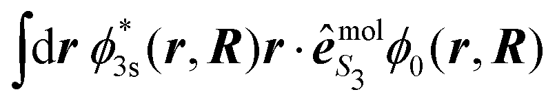 is evaluated at the equilibrium geometry R0 of the molecule in its ground state. This dipolar term thus consists of a global factor which can be also factored out in the expression (34) of the vibrational wavepacket. In other words, nuclear dynamics do not depend on S3 in the Franck–Condon approximation. However, our Franck–Condon simulations do show that the 2D-PECD, projected onto the VMI plane, depends on S3. This has to be related to the effective alignment (selection of molecular orientations according to
  ) operated by the pump during the excitation process. This anisotropy disappears at the level of angularly integrated PECD, as the usual b2-anisotropy remains hidden in measurements of total cross sections.
Importantly, beyond the Franck–Condon approximation, the amplitudes c3s,j read
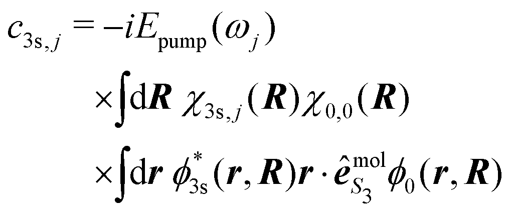 | (36) |
 is a function of R that depends on S3; e.g.,
 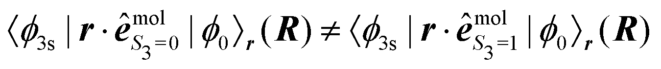 . The electronic dipolar term can no longer be factored out, so that both the amplitude and phase of the vibrational wavepacket, i.e. the nuclear dynamics, now explicitly depend on the polarization state S3 of the pump. As a matter of fact, we have mimicked non-Franck–Condon transitions by introducing two non-collinear dipoles in our calculations. This amounts to a discretized version of c3s,j in eqn (36) where
  . Even if we did not include explicitly the vibrational wavefunctions, this allowed us to represent the population of different regions of the 3s surface landscape, beyond the Franck–Condon assumption. In practice, the first dipole has been set to
 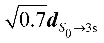 while the second one was
 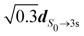 rotated in a direction perpendicular to the first one. The subsequent description of ionization has been made using S0 and 3s nuclear geometries for R1 and R2, respectively. We then obtained different angularly integrated PECDs for S3 = 0 (+8.58%) and S3 = ±1 (+4.87%), similarly to our experimental observations. On the basis of these last simulations and previous discussions, we conclude that non-Franck–Condon transitions are at play in the experiments. Such non-Franck Condon transitions have already been observed in standard VUV-PECD of methyloxirane,12 and in PhotoeXcitation Circular Dichroism (PXCD)50 involving a single intermediate electronic state in camphor. Similar transitions could be also at play in fenchone, but due to the weak b3, their fingerprint is not as visible as in camphor.
It has to be noted that as soon as the intermediate excited state is reached through absorption of n > 1 photons, the angularly integrated PECD does depend on the polarization state S3 of the pump in the Franck–Condon framework. This can be already understood in a simple two-photon excitation scheme where the absorption cross section, averaged over the molecular orientations, already depends on S3.51 This is highly beneficial to simulations of multiphoton PECD using either linearly or circularly polarized pump photons32 since the vibrational dynamics, which can be factored out from the ionization amplitude, does not need to be explicitly taken into account.
In its present form, our model cannot explain in depth the PECD time-transients observed in the (1 + 1′)-ionization process. Since it employs the Franck–Condon approximation, it is reliable for short delays and at asymptotic times where ionization occurs as the molecules are in their S0 and 3s equilibrium geometries, respectively (both regions are highlighted in Fig. 10(a) and (b)). However, the model allows one to understand how the rotational dephasing, coupled to the effective alignment induced by the pump and the shape of the intermediate state involved in the (1 + 1′)-ionization scheme, influences drastically the temporal evolution of the angularly resolved PECD and can also result in a switch of the PECD.
5 Conclusions
We have investigated the sensitivity of TR-PECD to isomerism effects using (−)-fenchone and (+)-camphor as prototypical molecules primarily excited in their 3s state.At short delays, strong differences are observed in the angular PECD between the two isomers. In order to understand these differences, we have developed a theoretical model, based on first order perturbation theory, where the nuclear geometry of the molecules is frozen throughout the (1 + 1′)-photon absorption. We have thus been able to highlight the crucial role of the shape of the intermediate excited state in this isomerism effect.
At longer delay, using a linearly polarized pump, we found that while no isomeric-dependent features appear in the TR-PES, the TR-PECD is drastically different between the two isomers, in both its time transients and temporal evolution of the angular structure. We varied the pump polarization, going from S3 = 0 to S3 = ±1, in order to decorrelate the different degrees of freedom. Indeed, in the context of a Franck–Condon vertical transition, the vibrational excitation in the 3s state is expected to be the same in both cases, and only the spatial molecular anisotropy, due to excitation, differs. The measurements showed that the time constants associated with the chiral observables are very different for S3 = 0 and S3 = ±1 in camphor. The PECD decays much faster for S3 = 0 than for S3 = ±1, with its time dependence being in the latter case close to the behavior observed in fenchone. We extended our model to take into account the rotational dephasing of the molecular orientations after the excitation step. The temporal evolution of the 2D PECD showed that the rotational degree of freedom is coupled to the pump-induced molecular alignment and to the shape of the intermediate excited state. However, the model yields identical integrated PECDs for S3 = 0 and S3 = ±1, in contrast to the experiment. We traced back the root of this behaviour by the use of the Franck–Condon approximation. Therefore, we inferred that the experiments reveal that non Franck–Condon transitions are at play in the (1 + 1′)-interaction scheme. The coupling of such vibrational dynamics to the external (rotational) degree of freedom is consistent with PECD time-transients depending on S3 and isomeric effects between fenchone and camphor.
The influence of the loss of anisotropy of excitation observed here may have consequences for the high-resolution REMPI-PECD measurements, which aim at addressing as a resonant intermediate state a given vibrational level of the electronic excited state. Recent measurements have shown that using nanosecond pulses, the REMPI-PECD was rather insensitive to the intermediate vibrational levels.16 As illustrated in Fig. 10, using shorter pulses may enable keeping the benefit of the anisotropy of excitation and reveal the influence of vibrational excitation. A trade-off between spectral resolution and a laser interaction duration shorter than the loss of anisotropy could be obtained by using tunable Fourier-limited picosecond pulses.
The high sensitivity of TR-PECD to molecular alignment revealed by our study indicates that resolving the 3D distributions of the PECD would provide more spectroscopic information, through the evolution of the anisotropy of the chiral response. The continuous variation of the degree of ellipticity of the exciting radiation, in a multiphoton pump scheme, would allow manipulating the anisotropy of excitation and the resulting dichroism.20 Furthermore, resolving the molecular alignment through coincidence electron ion imaging52 would enable drawing a complete picture of the relaxation dynamics, even if such a goal remains experimentally challenging in terms of acquisition time of the measurements.
Last, broadening the range of pump and probe photon energies would enable investigating other important processes, such as the vibrational relaxation subsequent to inner-shell electronic excitation and the photorelaxation of reactive excited states such as π* states, or to track the chiral response around conical intersections. Such studies would make TR-PECD an observable of choice to answer fundamental questions in photochemistry.
Conflicts of interest
There are no conflicts to declare.Acknowledgements
This project has received funding from the European Research Council (ERC) under the European Unions Horizon 2020 research and innovation program no. 682978 – EXCITERS, and 654148. We acknowledge the financial support of the French National Research Agency through ANR-14-CE32-0014 MISFITS and from the Région Nouvelle Aquitaine through RECHIRAM, as well as Université of Bordeaux.Notes and references
- B. Ritchie, Phys. Rev. A: At., Mol., Opt. Phys., 1976, 13, 1411–1415 CrossRef.
- I. Powis, J. Chem. Phys., 2000, 112, 301–310 CrossRef CAS.
- N. Böwering, T. Lischke, B. Schmidtke, N. Müller, T. Khalil and U. Heinzmann, Phys. Rev. Lett., 2001, 86, 1187–1190 CrossRef PubMed.
- L. Nahon, G. A. Garcia and I. Powis, J. Electron Spectrosc. Relat. Phenom., 2015, 204, 322–334 CrossRef CAS.
- S. Beaulieu, A. Comby, A. Clergerie, J. Caillat, D. Descamps, N. Dudovich, B. Fabre, R. Géneaux, F. Légaré, S. Petit, B. Pons, G. Porat, T. Ruchon, R. Taeb, V. Blanchet and Y. Mairesse, Science, 2017, 358, 1288–1294 CrossRef CAS PubMed.
- H. Ganjitabar, G. A. Garcia, L. Nahon and I. Powis, J. Chem. Phys., 2020, 153, 034302 CrossRef CAS PubMed.
- L. Nahon, L. Nag, G. Garcia, I. Myrgorodska, U. J. Meierhenrich, S. Beaulieu, V. Wanie, V. Blanchet, R. Géneaux and I. Powis, Phys. Chem. Chem. Phys., 2016, 18, 12696–12706 RSC.
- S. Turchini, D. Catone, N. Zema, G. Contini, T. Prosperi, P. Decleva, M. Stener, F. Rondino, S. Piccirillo, K. C. Princ and M. Speranza, ChemPhysChem, 2013, 14, 1723–1732 CrossRef CAS PubMed.
- S. Daly, M. Tia, G. A. Garcia, L. Nahon and I. Powis, Angew. Chem., Int. Ed., 2016, 128, 11220–11224 CrossRef.
- T. Lischke, N. Böwering, B. Schmidtke, N. Müller, T. Khalil and U. Heinzmann, Phys. Rev. A: At., Mol., Opt. Phys., 2004, 70, 022507 CrossRef.
- S. Daly, I. Powis, G. A. Garcia, H. Soldi-Lose and L. Nahon, J. Chem. Phys., 2011, 134, 064306 CrossRef PubMed.
- G. A. Garcia, L. Nahon, S. Daly and I. Powis, Nat. Commun., 2013, 4, 2132 CrossRef PubMed.
- M. M. RafieeFanood, H. Ganjitabar, G. A. Garcia, L. Nahon, S. Turchini and I. Powis, ChemPhysChem, 2018, 19, 921–933 CrossRef CAS PubMed.
- C. Lux, M. Wollenhaupt, T. Bolze, Q. Liang, J. Köhler, C. Sarpe and T. Baumert, Angew. Chem., Int. Ed., 2012, 51, 5001–5005 CrossRef CAS PubMed.
- C. S. Lehmann, N. B. Ram, I. Powis and M. H. M. Janssen, J. Chem. Phys., 2013, 139, 234307 CrossRef PubMed.
- A. Kastner, G. Koumarianou, P. Glodic, P. C. Samartzis, N. Ladda, S. T. Ranecky, T. Ring, S. Vasudevan, C. Witte, H. Braun, H.-G. Lee, A. Senftleben, R. Berger, G. B. Park, T. Schäfer and T. Baumert, Phys. Chem. Chem. Phys., 2020, 22, 7404–7411 RSC.
- S. Beaulieu, A. Ferré, R. Géneaux, R. Canonge, D. Descamps, B. Fabre, N. Fedorov, F. Légaré, S. Petit, T. Ruchon, V. Blanchet, Y. Mairesse and B. Pons, New J. Phys., 2016, 18, 102002 CrossRef.
- E. Bloch, S. Larroque, S. Rozen, S. Beaulieu, A. Comby, S. Beauvarlet, D. Descamps, B. Fabre, S. Petit, R. Taeb, A. J. Uzan, V. Blanchet, N. Dudovich, B. Pons and Y. Mairesse, Phys. Rev. X, 2021 Search PubMed , in press.
- H. Ganjitabar, R. Hadidi, G. A. Garcia, L. Nahon and I. Powis, J. Mol. Spectrosc., 2018, 353, 11–19 CrossRef CAS.
- A. Comby, E. Bloch, C. M. M. Bond, D. Descamps, J. Miles, S. Petit, S. Rozen, J. B. Greenwood, V. Blanchet and Y. Mairesse, Nat. Commun., 2018, 9, 5212 CrossRef CAS PubMed.
- M. M. R. Fanood, N. B. Ram, C. S. Lehmann, I. Powis and M. H. M. Janssen, Nat. Commun., 2015, 6, 7511 CrossRef CAS PubMed.
- A. Kastner, C. Lux, T. Ring, S. Züllighoven, C. Sarpe, A. Senftleben and T. Baumert, ChemPhysChem, 2016, 17, 1119–1122 CrossRef CAS PubMed.
- A. Comby, S. Beaulieu, M. Boggio-Pasqua, D. Descamps, F. Légaré, L. Nahon, S. Petit, B. Pons, B. Fabre, Y. Mairesse and V. Blanchet, J. Phys. Chem. Lett., 2016, 7, 4514–4519 CrossRef CAS PubMed.
- S. Beaulieu, A. Comby, B. Fabre, D. Descamps, A. Ferré, G. Garcia, R. Géneaux, F. Légaré, L. Nahon, S. Petit, T. Ruchon, B. Pons, V. Blanchet and Y. Mairesse, Faraday Discuss., 2016, 325–348 RSC.
- L. Nahon, G. A. Garcia, H. Soldi-Lose, S. Daly and I. Powis, Phys. Rev. A: At., Mol., Opt. Phys., 2010, 82, 032514 CrossRef.
- C. Lux, M. Wollenhaupt, C. Sarpe and T. Baumert, ChemPhysChem, 2015, 16, 115–137 CrossRef CAS PubMed.
- S. Beaulieu, A. Comby, D. Descamps, S. Petit, F. Légaré, B. Fabre, V. Blanchet and Y. Mairesse, J. Chem. Phys., 2018, 149, 134301 CrossRef CAS PubMed.
- N. Fedorov, S. Beaulieu, A. Belsky, V. Blanchet, R. Bouillaud, M. De Anda Villa, A. Filippov, C. Fourment, J. Gaudin, R. E. Grisenti, E. Lamour, A. Lévy, S. Macé, Y. Mairesse, P. Martin, P. Martinez, P. Noé, I. Papagiannouli, M. Patanen, S. Petit, D. Vernhet, K. Veyrinas and D. Descamps, Rev. Sci. Instrum., 2020, 91, 105104 CrossRef CAS PubMed.
- U. Even, I. Al-Hroub and J. Jortner, J. Chem. Phys., 2001, 115, 2069–2073 CrossRef CAS.
- M. Hillenkamp, S. Keinan and U. Even, J. Chem. Phys., 2003, 118, 8699–8705 CrossRef CAS.
- F. Pulm, J. Schramm, J. Hormes, S. Grimme and S. Peyerimhoff, Chem. Phys., 1997, 224, 143–155 CrossRef CAS.
- R. E. Goetz, T. A. Isaev, B. Nikoobakht, R. Berger and C. P. Koch, J. Chem. Phys., 2017, 146, 024306 CrossRef CAS PubMed.
- A. G. Harvey, Z. Mašín and O. Smirnova, J. Chem. Phys., 2018, 149, 064104 CrossRef PubMed.
- G. A. Garcia, L. Nahon and I. Powis, Rev. Sci. Instrum., 2004, 75, 4989–4996 CrossRef CAS.
- A. Blokhin, M. Gelin, E. Khoroshilov, I. Kryukov and A. Sharkov, Opt. Spectrosc., 2003, 95, 346–352 CrossRef CAS.
- G. A. Garcia, L. Nahon, S. Daly and I. Powis, Nat. Commun., 2013, 4, 2132 CrossRef PubMed.
- M. Schmidt, K. Baldridge, J. Boatz, S. Elbert, M. Gordon, J. Jenson, S. Koseki, N. Matsunaga, K. Nguyen, S. Su, T. Windus, M. Dupuis and J. Montgomery, J. Comput. Chem., 1993, 14, 1347–1363 CrossRef CAS.
- E. Runge and E. K. U. Gross, Phys. Rev. Lett., 1984, 52, 997–1000 CrossRef CAS.
- T. Yanai, D. P. Tew and N. C. Handy, Chem. Phys. Lett., 2004, 393, 51–57 CrossRef CAS.
- R. Krishnan, J. S. Binkley, R. Seeger and J. A. Pople, J. Chem. Phys., 1980, 72, 650–654 CrossRef CAS.
- A. D. Becke, Phys. Rev. A: At., Mol., Opt. Phys., 1988, 38, 3098–3100 CrossRef CAS PubMed.
- C. Lee, W. Yang and R. G. Parr, Phys. Rev. B: Condens. Matter Mater. Phys., 1988, 37, 785–789 CrossRef CAS PubMed.
- H. Goldstein, Classical Mechanics, Addison-Wesley, 1980 Search PubMed.
- D. Dill and J. L. Dehmer, J. Chem. Phys., 1974, 61, 692–699 CrossRef CAS.
- M. E. Rose and B. T. Feld, Phys. Today, 1957, 10, 30 CrossRef.
- B. H. Besler, K. M. Merz Jr. and P. A. Kollman, J. Comput. Chem., 1990, 11, 431–439 CrossRef CAS.
- D. C. Rapaport, Rigid molecules, Cambridge University Press, 2nd edn, 2004, pp. 199–244 Search PubMed.
- A. Kol, B. B. Laird and B. J. Leimkuhler, J. Chem. Phys., 1997, 107, 2580–2588 CrossRef CAS.
- D. Baykusheva, D. Zindel, V. Svoboda, E. Bommeli, M. Ochsner, A. Tehlar and H. J. Wörner, Proc. Natl. Acad. Sci. U. S. A., 2019, 116, 23923–23929 CrossRef CAS PubMed.
- S. Beaulieu, A. Comby, D. Descamps, B. Fabre, G. A. Garcia, R. Géneaux, A. G. Harvey, F. Légaré, Z. Mašín, L. Nahon, A. F. Ordonez, S. Petit, B. Pons, Y. Mairesse, O. Smirnova and V. Blanchet, Nat. Phys., 2018, 14, 484–489 Search PubMed.
- F. Zahariev and M. S. Gordon, J. Chem. Phys., 2014, 140, 18A523 CrossRef PubMed.
- M. Tia, M. Pitzer, G. Kastirke, J. Gatzke, H.-K. Kim, F. Trinter, J. Rist, A. Hartung, D. Trabert, J. Siebert, K. Henrichs, J. Becht, S. Zeller, H. Gassert, F. Wiegandt, R. Wallauer, A. Kuhlins, C. Schober, T. Bauer, N. Wechselberger, P. Burzynski, J. Neff, M. Weller, D. Metz, M. Kircher, M. Waitz, J. B. Williams, L. P. H. Schmidt, A. D. Müller, A. Knie, A. Hans, L. Ben Ltaief, A. Ehresmann, R. Berger, H. Fukuzawa, K. Ueda, H. Schmidt-Böcking, R. Dörner, T. Jahnke, P. V. Demekhin and M. Schöffler, J. Phys. Chem. Lett., 2017, 8, 2780–2786 CrossRef CAS PubMed.
| This journal is © the Owner Societies 2021 |