 Open Access Article
Preparation of CaMgAl-LDHs and mesoporous silica sorbents derived from blast furnace slag for CO2 capture†
Haojie Jianga,
Hongwei Guo *a,
Peng Li*a,
Yang Lib and
Bingji Yana
aShagang School of Iron and Steel, Soochow University, Suzhou 215021, P. R. China. E-mail: guohongwei@suda.edu.cn; lipeng@suda.edu.cn; Fax: +86-0512-62334926; Tel: +86-0512-62334926
bThe State Key Laboratory of Refractories and Metallurgy, School of Materials and Metallurgy, Wuhan University of Science and Technology, Wuhan 430081, China
First published on 19th February 2019
Abstract
High volume blast furnace slag (BFS) resulting from iron-making activities has long been considered a burden for the environment. Despite considerable research efforts, attempts to convert BFS into high value-added products for environmental remediation are still challenging. In this study, calcium–magnesium–aluminium layered double hydroxides (CaMgAl-LDHs) and ordered mesoporous silica material (MCM-41) sorbents were simultaneously synthesized from BFS, and their CO2 adsorption performance was evaluated. Calcium (Ca), magnesium (Mg) and aluminium (Al) were selectively extracted from BFS using hydrochloric acid. Leaching conditions consisting of 2 mol L−1 acid concentration, 100 °C leaching temperature, 90 min leaching time and a solid-to-liquid ratio of 40 g L−1 achieved a high leaching ratio of Ca, Mg and Al at 88.08%, 88.59% and 82.27%, respectively. The silica-rich residue (SiO2 > 98.6 wt%) generated from the leaching process could be used as a precursor for MCM-41 preparation. Chemical composition, surface chemical bonds, morphology and textural properties of the as-synthesized CaMgAl-LDHs and MCM-41 sorbents were determined. Both the CaMgAl-LDHs and MCM-41 sorbents were found to be thermally stable and exhibited comparable adsorption uptake and rates over 20 CO2 adsorption/desorption cycles. This work demonstrated that a total solution for the utilisation of BFS can be achieved and the resulting valuable products, i.e. CaMgAl-LDHs and MCM-41 are promising sorbents for CO2 capture.
1. Introduction
One of the most significant environmental challenges faced by humans in the 21st century is global warming caused by the increase in carbon dioxide levels.1 In response to the issue of greenhouse gases, many countries have proposed a series of carbon emission reduction plans. Notably, research into options for the capture, utilisation and long-term storage of carbon dioxide has become a hot topic in the field of low-carbon and zero-carbon technologies, which include renewable energy, clean energy and carbon capture & storage (CCS).1–5 (CCS) is being investigated as a potential option to capture CO2 at the source of generation from various industrial facilities, and to transport and separate the captured CO2 in storage areas.5–9Iron and steel manufacturing are not only major energy-consuming industries but also major emitters of greenhouse gases. The generation of large amounts of solid waste including blast furnace slag (BFS) and steel slag (SS) has caused severe environmental problems involving water and soil contamination, and local air pollution.10 To reduce or resolve these growing environmental concerns, many current research activities are focusing on the development of new waste management strategies such as the preparation of useful materials from waste. In the past ten years, mineral carbonation is the most dynamic and the fastest growing CO2 sequestration technology. In mineral carbonation, CO2 gas is stored by promoting the reaction of magnesium or calcium oxides in silicate minerals with carbon dioxide to form carbonates;4 BFS and SS from the steel industry contain a large number of alkaline oxides, such as CaO and MgO, which can be used for CO2 capture.11
In Finland, Eloneva et al.2–5 studied the possibility of utilizing SS for the production of pure calcium carbonate. They found that dilute acetic acid only selectively dissolved calcium from the steel slag. Tian et al.12 proposed a process for simultaneously producing CaO-based CO2 sorbents and high-quality iron ore from waste SS. The results showed that the extraction of calcium was always accompanied by the undesired dissolution of elemental impurities such as Al, Mg and Fe, resulting in decreased CO2 adsorption capacity.
As well as the intensive research activity on SS, BFS is also considered as valuable raw material in CO2 sequestration. Compared with SS, BFS is more greatly enriched in elemental Ca, Mg, Si and Al, which together account for around 90% of its total mass; this means that the aqueous extraction of BFS could potentially leads to less contamination. Seonhye Lee et al.1 studied the indirect sequestration of CO2 using BFS as the raw material and achieved 49.76% extraction efficiency of Ca and 95.69% carbonation efficiency using NH4NO3 under typical conditions (2 mol L−1 solvent concentration, 30 °C reaction temperature, 60 min reaction time, 10 g L−1 solid-to-liquid ratio).
In their early research, Yasutaka Kuwahara et al.13 successfully synthesised a Ca-based layered double hydroxide (LDH) compound from BFS, and applied it in CO2 fixation. In their methodology, the hydrochloric acid leaching resulted in a precursor solution suited for LDH preparation and hydrated silica gel. Inspired by this result, in this paper, a facile method for the simultaneous preparation of (LDHs) and ordered mesoporous silica (MCM-41) materials from BFS is reported. The objectives of this research are to focus on: (i) clarifying the influence of acid leaching conditions on the dissolution behavior of BFS, and seeking optimised conditions for the selective and highly efficient dissolution of elemental calcium, magnesium and aluminium; (ii) making best use of the BFS through synthesising LDHs and MCM-41 sorbents by recovering the leachate and residue after solvent extraction and subsequent structural characterisation, (iii) the evaluation of CO2 sequestration ability for both sorbents through adsorption–desorption measurements.
2. Experimental
2.1 Materials and test facilities
Water granulated blast furnace slag was received from the Shagang Steel Co., Ltd., China. The slag was crashed and ball milled to a particle size of less than 74 μm. The chemical composition of the BFS was analysed using X-ray fluorescence (XRF, SHIMADZU-EDX800, Japan), and the concentrations of Ca, Si, Mg and Al in the solution were measured using inductively coupled plasma-optic emission spectrometry (ICP-OES, Vista-MPX, Varian, USA). The compositionA results from XRF quantitative measurements are shown in Table 1, revealing that the BFS was mainly composed of 36.84 wt% CaO, 34.27 wt% SiO2, 10.14 wt% MgO and 14.47 wt% Al2O3, which together accounted for 95% of the total mass. Results of the ICP-OES analysis gave the compositionB of the solution, with these values used for estimating the leaching ratio of metal ions from the BFS.| Al2O3 | SiO2 | CaO | MgO | K2O | Fe2O3 | Na2O | MnO | |
|---|---|---|---|---|---|---|---|---|
| CompositionA | ||||||||
| wt% | 14.47 | 34.27 | 36.84 | 10.14 | 0.52 | 0.53 | 0.43 | 0.52 |
![[thin space (1/6-em)]](https://www.rsc.org/images/entities/char_2009.gif) |
||||||||
| CompositionB | ||||||||
| wt% | 14.66 | 32.77 | 36.14 | 10.79 | NA | 0.26 | NA | NA |
The mineralogical phases were identified by X-ray diffraction (XRD, UltimaI VX, Rigaku, Japan) with CuKα radiation, utilising a generator voltage of 40 kV and tube current of 40 mA. Small-angle X-ray scattering (SAXS) measurements were carried out at room temperature using a SAXSess mc2 (Anton Paar) instrument.
Surface functional groups were determined with Fourier transform infrared spectroscopy (Jasco FT-IR-4100) with KBr in the 1800–400 cm−1 region.
Morphologies were characterized by scanning electron microscope (SEM, SU5000, Hitachi, Japan) and a transmission electron microscope (TEM, TECNAI G2 F20, FEI, USA). Textural properties were investigated by N2 adsorption–desorption measurements using an ASAP 2000 instrument (Micromeritics, USA). Thermogravimetric analysis (TGA) was performed to evaluate thermal stability using a TGA-50/50H analyser (Shimadzu, Kyoto, Japan).
2.2 Experimental methods
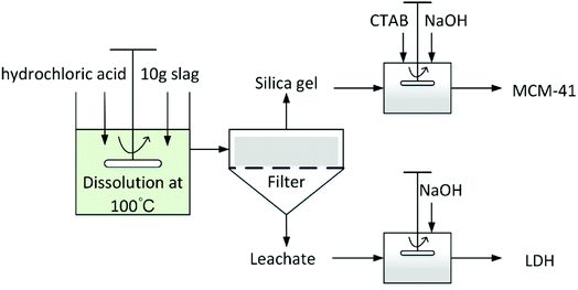
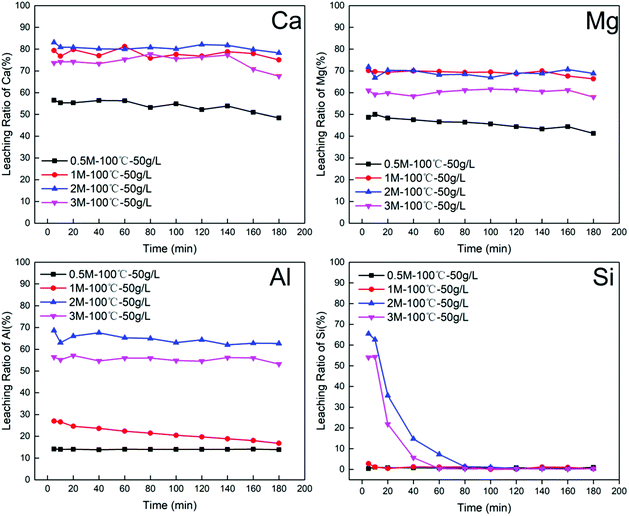
BFS (10 g) was added to the reactor containing a specific concentration (0.5 M, 1 M, 2 M or 3 M) of hydrochloric acid (11.74 M, Enox) at 100 °C. To monitor the progression of the dissolution, 5 mL of aqueous solution was sampled using quantitative pipette at 5, 10, 20, 40, 60, 80, 100, 120, 140, 160 and 180 min after the slag was added.
The leaching ratio of a specific element was calculated by the following equation:
 | (1) |
| Composition | SiO2 | Al2O3 | MgO | TiO2 | Fe2O3 | SO3 | MnO | Cl |
|---|---|---|---|---|---|---|---|---|
| wt% | 98.581 | 0.094 | 0.048 | 0.017 | 0.013 | <0.01 | <0.01 | 0.689 |
In a typical procedure, n-cetyltrimethylammonium bromide (CTAB, 1.457 g) was dissolved in of deionised water (60 mL) at room temperature. Then, acid leaching residue (1.2 g) and NaOH (1 g) were added to the CTAB aqueous solution. The mixture was stirred until a clear solution was obtained, following which NaOH or HCl solution was added dropwise to adjust the pH to 11. The resulting solution was further stirred for another one hour, then placed in a Teflon-lined autoclave for hydrothermal treatment at 80 °C for 48 h. After that, the slurry was filtered, washed repeatedly using deionised water and air-dried overnight at 100 °C. Finally, the as-synthesized silica powder was calcined at 550 °C in air for 6 h.
3. Results and discussion
3.1 Leaching of BFS
| Si(OH)4 + Si(OH)4 → (HO)3Si-O-Si(OH)3 + H2O | (2) |
| (HO)3Si-O-Si(OH)3 → (SiO2)2 + 3H2O | (3) |
| Concentration of HCl (M) | Temperature (°C) | S/L ratios (g L−1) | Elemental selectivity (%) | n(M2+)/n(M3+) | |||
|---|---|---|---|---|---|---|---|
| Ca2+ (%) | Mg2+ (%) | Al3+ (%) | Si4+ (%) | ||||
| a Elemental selectivity (%) = nx/(nCa + nMg + nAl + nSi) × 100%, x = Ca, Mg, Al, Si. | |||||||
| 0.5 | 100 | 50 | 67.94 | 22.36 | 8.52 | 1.17 | 10.60 |
| 1 | 100 | 50 | 69.36 | 23.59 | 6.81 | 0.24 | 13.65 |
| 2 | 100 | 50 | 58.99 | 20.05 | 20.73 | 0.23 | 3.81 |
| 3 | 100 | 50 | 59.55 | 19.67 | 20.47 | 0.31 | 3.87 |
| 2 | 70 | 50 | 35.90 | 15.45 | 17.13 | 31.52 | 3.00 |
| 2 | 90 | 50 | 36.45 | 15.63 | 17.16 | 30.77 | 3.04 |
| 2 | 100 | 30 | 52.70 | 21.01 | 24.11 | 2.17 | 3.06 |
| 2 | 100 | 40 | 50.89 | 20.38 | 22.91 | 5.82 | 3.11 |
| 2 | 100 | 60 | 50.54 | 20.96 | 23.47 | 5.03 | 3.05 |
| 2 | 100 | 70 | 52.33 | 22.08 | 24.10 | 1.49 | 3.09 |
Another important index that also needs to be considered is the molar ratio of divalent cations to trivalent cations in the leachate solution: the molar ratio should meet the general requirements (between 2 and 4)15 for the preparation of LDHs. The value of n(M2+)/n(M3+) is strongly related to the hydrochloric acid concentration. With increased acid concentration, n(M2+)/n(M3+) decreased, which suggests that the trivalent metal (Al3+) shows stronger resistance against acid attack compared with divalent alkali metals (Ca2+, Mg2+).
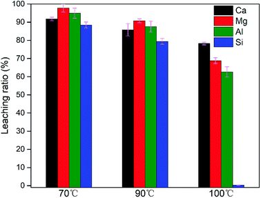
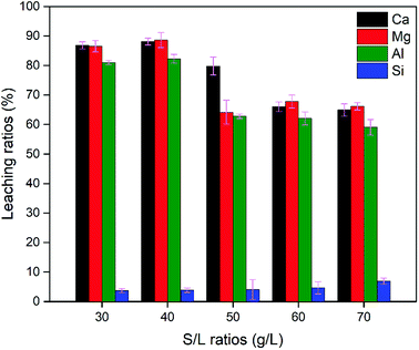
In summary, leaching conditions need to be rationally chosen for obtaining a high leaching ratio of elemental Ca, Mg and Al, low elemental selectivity for Si and a suitable n(M2+)/n(M3+). Leaching conditions comprising 2 M acid concentration, 100 °C leaching temperature, 90 min leaching time and a S/L ratio of 40 g L−1 allowed a high leaching ratio of Ca, Mg and Al to be achieved, at 88.08%, 88.59% and 82.27%, respectively, 5.82% of Si and a value of 3.11 for n(M2+)/n(M3+).
3.2 Characterization of CaMgAl-LDHs sorbent
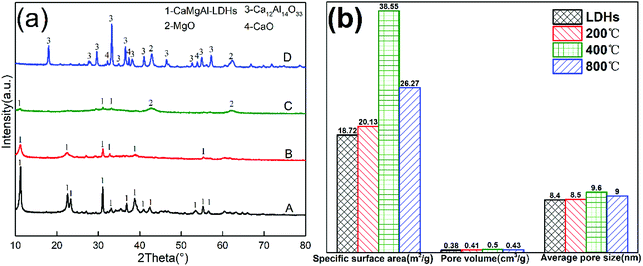
Fig. 5(a) shows the XRD pattern of as-synthesized CaMgAl-LDHs. All the sharp reflections with a high-degree of crystallinity were attributed to the successful formation of LDHs. The LDHs showed obvious crystallographic changes as a result of calcination at different temperatures in air. The sample maintained hydrotalcite structure when the calcination temperature was 200 °C. Once calcined at 400 °C, the sample showed weak reflections characteristic of hydrotalcite with a small amount of periclase, indicating decomposition of the layered structure. Calcination above 800 °C generated new crystalline phases assignable to CaO, MgO and mayenite (Ca12Al4O33). The thermal events of as-synthesized CaMgAl-LDHs from BFS was further studied by TGA analysis. The thermal decomposition of the CaMgAl-LDHs occurred in three main weight loss steps (ESI, Fig. S1†). In addition, this LDHs had a nominal structural formula of Ca1.89Mg0.89Al1.0(OH)7.5Cl0.83(CO3)0.11·yH2O, and most of the intercalated anions were Cl− (ESI, Table S1†).The textural properties obtained from BET analysis are presented in Fig. 5(b). The specific surface area increased with increase in calcination temperature from 200 °C to 400 °C. The sample after calcination at 400 °C for 4 h had a specific surface area of 38.55 m2 g−1, which was twice as large as that of the LDHs. A slight increase in average pore diameter and pore volume were also observed. When the temperature further increased to 800 °C, the crystallisation of resulting oxides resulted in a decreased surface area and porosity.
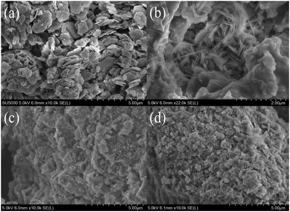
SEM micrographs of as-synthesized LDHs calcined at different temperatures are shown in Fig. 6. Fig. 6(a) shows the formation of a typical plate-like structure with well-defined hexagonal shape.16 The particle size of LDHs was about 1 μm and the thickness was less than 40 nm. Fig. 6(b) shows that the plate-like particles stacked together after calcination at 200 °C. When the temperature further increased, calcination resulted in the disappearance of characteristic LDHs features with the formation of amorphous mixed oxides (Fig. 6(c)), which further developed into mineral crystallites as a consequence of sintering events (Fig. 6(d)).17
 | ||
| Fig. 6 SEM images of LDHs sorbents calcined at different temperatures: (a) as-synthesized, (b) 200 °C, (c) 400 °C and (d) 800 °C. | ||
3.3 Characterization of MCM-41 sorbent
The SEM image in Fig. 7(a) shows that the as-synthesized mesoporous silica nanoparticles on a scale of less than 200 nm had a good dispersity, with some coalescence into aggregates. The TEM micrograph in Fig. 7(b) reveals a highly ordered 2D hexagonal pore structure array of the MCM-41 type silica; this feature was also confirmed by the presence of (100), (110) and (200) plane reflections in Fig. 7(c).18 The diameter between the fringes of the pore in the mesoporous structure was estimated to be around 3 nm, which is in good agreement with the BJH pore size distribution analysis in Fig. 7(d), having a primary distribution in the range of 2.6–2.8 nm. The sorption isotherm in Fig. 7(d) shows a type IV isotherm according to the IUPAC classification with a sharp increase step in the relative pressure region of 0.31–0.35. This was attributed to capillary condensation within the narrow distribution of mesopores.19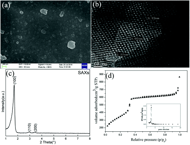 | ||
| Fig. 7 (a) SEM image and (b) TEM image of MCM-41 sorbent prepared from BFS; (c) SAXs scattering pattern; (d) N2 adsorption–desorption isotherm and pore size distribution. | ||
Textural properties of MCM-41 including BET surface area (SBET), total pore volume (Vp), average pore radius (DBJH) and the wall thickness (bp) are shown in Table 4. This material had a surface area of 1270 m2 g−1, much higher than when synthesized from fly ash (732 m2 g−1),20 iron ore tailings (527 m2 g−1),21 sodium silicate (874 m2 g−1)22 and pure TEOS (1100 m2 g−1).20 The thickness of pore walls was comparable at 1.04 nm with results in the previous literature.23
| Sample | SBET (m2 g−1) | Vp (cm3 g−1) | DBJH (nm) | d100 (nm) | bp (nm) |
|---|---|---|---|---|---|
a SBET, specific surface area calculated using BET equation. Vp, the total pore volumes were determined at a P/P0 value of 0.995. DBJH, the mean pore size distributions were determined by BJH mode applied to the desorption branches of the isotherms. bp, the pore wall thickness, calculated from equation.24 bp = 2d100/31/2 − DBJH, where d100 refers to the interplanar spacing of the (100) reflection by Bragg's equation (2d100![[thin space (1/6-em)]](https://www.rsc.org/images/entities/char_2009.gif) sin sin![[thin space (1/6-em)]](https://www.rsc.org/images/entities/char_2009.gif) θ = λ). θ = λ). |
|||||
| MCM-41 | 1270 | 1.342 | 3.034 | 3.531 | 1.04 |
3.4 Evaluation of CO2 capture performance
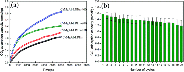
The CO2 adsorption behaviour of as-synthesized Ca1.89Mg0.89Al1.0-LDHs and after calcination at 200 °C, 400 °C, 800 °C, denoted as CaMgAl-LDHs-200, CaMgAl-LDHs-400, CaMgAl-LDHs-800, respectively, was measured at 400 °C. As seen from Fig. 8(a), after calcination at 400 °C for 4 h, CaMgAl-LDHs-400 exhibited a first contact capacity of 1.58 mmol g−1, almost 2 times greater than that of CaMgAl-LDHs without thermal activation. However, calcination at 800 °C caused a great decline in the CO2 adsorption. These results were in agreement with those of Ram Reddy et al.,25 indicating that there exists an optimised thermal activation temperature for CaMgAl-LDHs. The events of dehydroxylation, decomposition of intercalated anions, followed by crystallization upon thermal calcination (confirmed by the XRD and TGA analyses) gave rise to the variation in surface area and a number of active basic sites, thus having a great influence on the CO2 uptake.The thermal stability of CaMgAl-LDHs-400 was evaluated through continuous CO2 adsorption/desorption cycles. As shown in Fig. 8(b), CaMgAl-LDHs-400 demonstrates good reusability and cyclic performance throughout the 20 adsorption/desorption cycles. After 20 times cycles, the CaMgAl-LDHs-400 sorbent still adsorbs around 1.2 mmol g−1 of CO2 at 400 °C and 1 atm, CO2 adsorption capacity reduces 24%.
As depicted in Fig. 9(a), for MCM-41, the highest CO2 adsorption capacity increases from 0.95 to 1.24 mmol g−1 when the adsorption temperature increases from 25 to 75 °C, which is a characteristic feature of physisorption processes.26 However, the adsorption capacity decreased slightly to 1.13 mmol g−1 when the temperature exceeded 100 °C, which could be related to the dominant CO2 desorption reaction at high temperature. The adsorption/desorption cycles for MCM-41 were conducted at 75 °C. As shown in Fig. 9(b), there was about 20% deterioration in the adsorption capacity after 20 adsorption/desorption cycles, indicating that the MCM-41 sorbents had a good thermal stability.
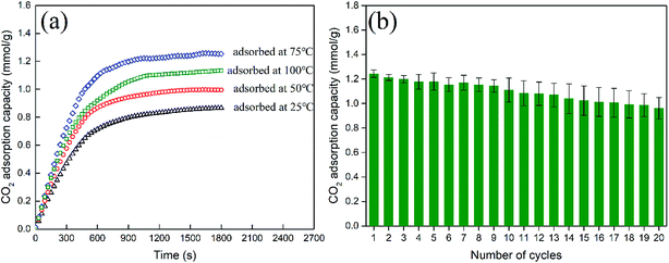 | ||
| Fig. 9 (a) The first CO2 contact capacities of MCM-41 sorbent at different temperatures (b) adsorption/desorption cycles for MCM-41(adsorbed at 75 °C, desorbed at 105 °C). | ||
3.5 Adsorptive mechanism for the two prepared composites for CO2 capture
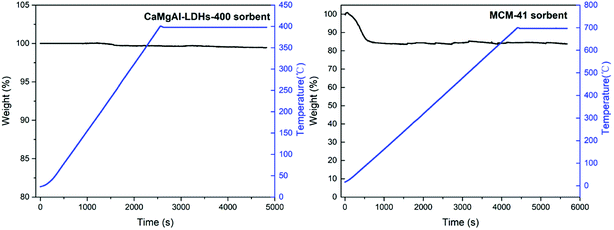
The composite stability for the prepared two composites was studied using the thermogravimetric analysis with results shown in Fig. 10. LDHs-400 sample was heated to 400 °C and maintained for a while, the weight loss was small. Similarly, MCM-41 sample was heated to 700 °C and maintained for a while, the weight loss was due to the adsorbed gas and water at the beginning and did not change as the temperature rised to 700 °C. This confirmed that both composites had good stability.As depicted Fig. 8(a), the LDHs calcined at 400 °C has a maximum adsorption capacity, which was most likely due to the optimum balance between the surface area and enough basic sites.25 The BET analysis for LDHs calcined at different temperatures in Fig. 5(b) supported this theory. The LDHs-400 sample, which is an amorphous mixed oxide phase, had the maximum BET surface area compared to the other samples at 38.55 m2 g−1. The LDHs-200 sample had the minimum BET surface area because its layered structure was maintained, with CO32− ions occupying the basic sites. Calcination at higher temperature (800 °C) decomposed most CO32− ions to release some basic sites for CO2 adsorption but resulted in a low BET surface area due to the phase transformation of amorphous mixed oxide into crystalline spinel, CaO and MgO phases. So, the LDHs-400 sample had not only the highest surface area but also enough basic sites for improving the CO2 adsorption performance.
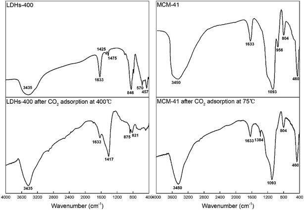
FTIR spectra patterns of CaMgAl-LDHs-400 and MCM-41 before and after adsorption are shown in Fig. 11. For LDHs-400, the reflection at 1633 cm−1 for LDHs material was the δH2O mode of interlayer water molecules.27 The relatively weak CO32− reflection at 1425–1475 cm−1 indicated a low level of contamination with CO2 before adsorption,28 while after CO2 adsorption the corresponding band located at around 1417 cm−1 was strong. The AlO6 stretching mode with the indicative reflection around 457 cm−1 was observed after calcination.26 The new reflection at 846 cm−1 indicated the presence of Ca–O bonding, which was consistent with previous results reported in the synthesis of hydrotalcite with varied (Ca + Mg)/Al molar ratios.29 After CO2 adsorption, the samples exhibited extremely weak vibration peaks at 1633 cm−1 and the disappearance of other vibration peaks. The disappearance of peaks related to metal–oxygen vibrations at low wavenumber of around 500 cm−1 was due to the chemical reaction between basic sites and CO2.
For MCM-41, the band around 3450 cm−1 attributed to hydrogen bonded surface silanols (Si–OH) and adsorbed water molecules were due to O–H stretching and the band at 1633 cm−1 was due to bending vibrations of adsorbed water molecules. The peaks centred at 1093 cm−1, 804 cm−1 and 460 cm−1 corresponded to the asymmetric stretching, symmetric stretching and rocking vibrations of the Si–O–Si bonds, respectively. The band appearing at 956 cm−1 was attributed to Si–O stretching in Si–OH. Silanol groups (Si–OH) on the surface of MCM-41 maybe the adsorption sites for capturing CO2 molecules.30 After CO2 adsorption, the band at 956 cm−1 disappeared and a very weak band at 1384 cm−1 was observed for the symmetric stretching mode of linear CO2 which verified that physisorbed CO2 on mesoporous silica was detected.31 The intensity of band corresponded to OH stretching of free silanol groups around 3450 cm−1 decreased after CO2 adsorption and a weakly bonded adduct between silanol groups and CO2: –OH⋯O![[double bond, length as m-dash]](https://www.rsc.org/images/entities/char_e001.gif) C
C![[double bond, length as m-dash]](https://www.rsc.org/images/entities/char_e001.gif) O formed which can easily break down as the temperature increases. As depicted Fig. 9(a), the CO2 adsorption capacity at higher temperature (100 °C) decreased because interaction between CO2 and silanol groups is van der Waals force, which does not favor the adsorption at higher temperatures.32
O formed which can easily break down as the temperature increases. As depicted Fig. 9(a), the CO2 adsorption capacity at higher temperature (100 °C) decreased because interaction between CO2 and silanol groups is van der Waals force, which does not favor the adsorption at higher temperatures.32
3.6 Comparison of the CO2 adsorption capacities of various materials
Different kinds of LDHs and mesoporous silica and their CO2 adsorption performances are compared in Table 5. The maximum CO2 adsorption capacity of CaMgAl-LDHs derived from BFS is 1.66 mmol g−1, which is higher than that of other LDHs synthesized using pure reagents. The maximum CO2 adsorption capacity of MCM-41 derived from BFS was 1.25 mmol g−1, which is comparable to other mesoporous silica synthesized from other materials. Comparing the results of this study with those reported in literature, BFS was found to be a promising raw material for CaMgAl-LDHs and MCM-41 production and their further use as efficient sorbents for capturing CO2.| Sorbents | Materials | CO2 uptake | Ref. |
|---|---|---|---|
| LDHs | Mg3Al-stearate-LDH-400 | 1.30 mmol g−1 at 300 °C, 1 bar | 33 |
| Ca3Al-LDH-550 | 0.87 mmol g−1 at 350 °C, 1 bar | 34 | |
| Mg3Al-LDH-550 | 1.18 mmol g−1 at 350 °C, 1 bar | 34 | |
| CaMg2Al-LDH-550 | 1.28 mmol g−1 at 350 °C, 1 bar | 34 | |
| Nano-sized 20 wt% K2CO3 impregnated Mg3Al-LDH-400 | 1.21 mmol g−1 at 200 °C, 1 bar | 35 | |
| Ca1.89Mg0.89Al1.0-LDHs-400 | 1.66 mmol g−1 at 400 °C, 1 bar | In this study | |
| Mesoporous silica | MCM-41/CPA | 1.5 mmol g−1 at 25 °C, 1 bar | 36 |
| MCM-48/CPA | 1.1 mmol g−1 at 25 °C, 1 bar | 36 | |
| MCM-41-NH2 | 1.15 mmol g−1 at 30 °C, 2.1 bar | 37 | |
| TRI-PE-MCM-41 | 2.21 mmol g−1 at 55 °C, 1 bar | 38 | |
| MCM-41 | 1.25 mmol g−1 at 75 °C, 1 bar | In this study |
4. Conclusions
In this work, the conversion of blast furnace slag into two different kinds of promising sorbents of CO2 has been presented. The calcium, magnesium, aluminium in BFS were selectively extracted by hydrochloric acid and used for preparation of layered double hydroxides (LDHs). The leaching residue which contained a high amount of silica was utilised for MCM-41 material synthesis. Several operating variables including initial hydrochloric acid concentration, leaching temperature, solid-to-liquid ratio, and leaching time were optimised. It was found that higher hydrochloric acid concentration, higher leaching temperature, and longer leaching time could promote silica gel formation; this provided a great advantage for the selective leaching out of calcium, magnesium, aluminium with high efficiency. Characterisation of the as-synthesized CaMgAl-LDHs and MCM-41 sorbents was performed to determine chemical composition, morphology and textural properties. The structural formula of CaMgAl-LDHs was determined as Ca1.89Mg0.89Al1.0(OH)7.5Cl0.83(CO3)0.11·yH2O, with Cl− as the predominate intercalated anion. Thermal calcination at 400 °C enhanced the specific surface area, thus leading to improved CO2 uptake and a maximum CO2 adsorption capacity of 1.58 mmol g−1 at 400 °C. The MCM-41 sorbents derived from BFS exhibited a high surface area of 1270 m2 g−1 and showed comparable CO2 adsorption capacity with a value of 1.24 mmol g−1 at 75 °C. In the CO2 adsorption/desorption cycles, both sorbents showed good reusability and cyclic performance. With all these results, the CaMgAl-LDHs and MCM-41 sorbents derived from blast furnace slag are promising sorbents for practical applications in the field of CO2 capture.Conflicts of interest
There are no conflicts to declare.Acknowledgements
The National Natural Science Foundation of China (No. 51574169, No. 51604178, No. 51704202, No. 51604202, No. 51774209), the Natural Science Foundation of the Jiangsu Higher Education Institutions of China (No. 17KJB450002), are duly acknowledged for their financial support. The authors also are grateful for the analysis support from Soochow University.References
- S. Lee, J. W. Kim, S. Chae, J. H. Bang and S. W. Lee, J. CO2 Util., 2016, 16, 336–345 CrossRef CAS.
- S. Teir, S. Eloneva, C. J. Fogelholm and R. Zevenhoven, Energy, 2007, 32, 528–539 CrossRef CAS.
- S. Eloneva, S. Teir, J. Salminen, C. J. Fogelholm and R. Zevenhoven, Energy, 2008, 33, 1461–1467 CrossRef CAS.
- S. Eloneva, S. Teir, J. Salminen, C. J. Fogelholm and R. Zevenhoven, Ind. Eng. Chem. Res., 2008, 47, 7104–7111 CrossRef CAS.
- S. Eloneva, S. Teir, J. Savolahti, C. Fogelholm and R. Zevenhoven, Proceeding ECOS 2007, Padova, Italy, 2007, vol. II, pp. 1389–1396 Search PubMed.
- C. Hall, D. J. Large, B. Adderley and H. M. West, Miner. Eng., 2014, 65, 156–162 CrossRef CAS.
- A. jun Xu, H. ning Zhang, Y. Yang, J. Cui, D. feng He and N. yuan Tian, J. Iron Steel Res. Int., 2012, 19, 34–38 CrossRef.
- J. H. Bang, S. W. Lee, C. Jeon, S. Park, K. Song, W. J. Jo and S. Chae, Energies, 2016, 9(12), 996 CrossRef.
- W. Bao, H. Li and Z. Yi, Ind. Eng. Chem. Res., 2010, 49, 2055–2063 CrossRef CAS.
- J. Wang, L. Huang, R. Yang, Z. Zhang, J. Wu, Y. Gao, Q. Wang, D. O'Hare and Z. Zhong, Energy Environ. Sci., 2014, 7, 3478–3518 RSC.
- S. H. Wang, Y. Bin Wang, Y. M. Dai and J. M. Jehng, Appl. Catal., A, 2012, 439–440, 135–141 CrossRef CAS.
- S. Tian, J. Jiang, F. Yan, K. Li, X. Chen and V. Manovic, Green Chem., 2016, 18, 4022–4031 RSC.
- Y. Kuwahara and H. Yamashita, ISIJ Int., 2015, 55, 1531–1537 CrossRef CAS.
- K. Song, S. Park, W. Kim, C. Jeon and J.-W. Ahn, Metals, 2017, 7, 199 CrossRef CAS.
- Q. Wang and D. Ohare, Chem. Rev., 2012, 112, 4124–4155 CrossRef CAS PubMed.
- A. P. Tathod and O. M. Gazit, Cryst. Growth Des., 2016, 16, 6709–6713 CrossRef CAS.
- A. C. Vieira, R. L. Moreira and A. Dias, J. Phys. Chem. C, 2009, 113, 13358–13368 CrossRef CAS.
- K. Flodström and V. Alfredsson, Microporous Mesoporous Mater., 2003, 59, 167–176 CrossRef.
- P. Selvam, S. K. Bhatia and C. G. Sonwane, Ind. Eng. Chem. Res., 2001, 40, 3237–3261 CrossRef CAS.
- H. Misran, R. Singh, S. Begum and M. A. Yarmo, J. Mater. Process. Technol., 2007, 186, 8–13 CrossRef CAS.
- H. Yu, X. Xue and D. Huang, Mater. Res. Bull., 2009, 44, 2112–2115 CrossRef CAS.
- Y. Y. Zhou, X. xuan Li and Z. xing Chen, Powder Technol., 2012, 226, 239–245 CrossRef CAS.
- P. Kumar, N. Mal, Y. Oumi, K. Yamana and T. Sano, J. Mater. Chem., 2001, 11, 3285–3290 RSC.
- D. Zhao, Q. Huo, J. Feng, B. F. Chmelka and G. D. Stucky, J. Am. Chem. Soc., 1998, 120, 6024–6036 CrossRef CAS.
- M. K. Ram Reddy, Z. P. Xu, G. Q. Lu and J. C. D. Da Costa, Ind. Eng. Chem. Res., 2006, 45, 7504–7509 CrossRef CAS.
- R. L. Frost, H. J. Spratt and S. J. Palmer, Spectrochim. Acta, Part A, 2009, 72, 984–988 CrossRef PubMed.
- R. Galindo, A. López-Delgado, I. Padilla and M. Yates, Appl. Clay Sci., 2014, 95, 41–49 CrossRef CAS.
- A. Boumaza, L. Favaro, J. Lédion, G. Sattonnay, J. B. Brubach, P. Berthet, A. M. Huntz, P. Roy and R. Tétot, J. Solid State Chem., 2009, 182, 1171–1176 CrossRef CAS.
- J. Zhou, Z. P. Xu, S. Qiao, Q. Liu, Y. Xu and G. Qian, J. Hazard. Mater., 2011, 189, 586–594 CrossRef CAS PubMed.
- W. Wang, J. Li, X. Wei, J. Ding, H. Feng, J. Yan and J. Yang, Appl. Energy, 2015, 142, 221–228 CrossRef CAS.
- Z. Bacsik, N. Ahlsten, A. Ziadi, G. Zhao, A. E. Garcia-Bennett, B. Martín-Matute and N. Hedin, Langmuir, 2011, 27, 11118–11128 CrossRef CAS PubMed.
- T. Witoon and M. Chareonpanich, Songklanakarin J. Sci. Technol., 2012, 34, 403–407 CAS.
- Q. Wang, H. H. Tay, Z. Zhong, J. Luo and A. Borgna, Energy Environ. Sci., 2012, 5, 7526–7530 RSC.
- P. W. Xiao, J. Y. Jun, J. Cheng, P. H. Zheng and P. X. Zhi, Environ. Sci. Technol., 2008, 42, 614–618 CrossRef.
- Q. Wang, Y. Gao, J. Luo, Z. Zhong, A. Borgna, Z. Guo and D. O'Hare, RSC Adv., 2013, 3, 3414–3420 RSC.
- M. Bhagiyalakshmi, L. J. Yun, R. Anuradha and H. T. Jang, J. Porous Mater., 2010, 17, 475–484 CrossRef CAS.
- M. R. Mello, D. Phanon, G. Q. Silveira, P. L. Llewellyn and C. M. Ronconi, Microporous Mesoporous Mater., 2011, 143, 174–179 CrossRef CAS.
- Y. Belmabkhout, R. Serna-Guerrero and A. Sayari, Adsorption, 2011, 17, 395–401 CrossRef CAS.
Footnote |
| † Electronic supplementary information (ESI) available. See DOI: 10.1039/c8ra08458k |
| This journal is © The Royal Society of Chemistry 2019 |

