 Open Access Article
Creative Commons Attribution 3.0 Unported Licence
A high performance lithium-ion–sulfur battery with a free-standing carbon matrix supported Li-rich alloy anode†
Tao
Zhang
a,
Min
Hong
b,
Jun
Yang
 *a,
Zhixin
Xu
a,
Jiulin
Wang
 *a,
Yongsheng
Guo
c and
Chengdu
Liang
c
aShanghai Electrochemical Energy Devices Research Center, School of Chemistry and Chemical Engineering, Shanghai Jiao Tong University, Shanghai 200240, P. R. China. E-mail: yangj723@sjtu.edu.cn; wangjiulin@sjtu.edu.cn
bDepartment of Micro/Nano Electronics, School of Electronic Information and Electrical Engineering, Shanghai Jiao Tong University, Shanghai 200240, P. R. China
cResearch Institute, Ningde Contemporary Amperex Technology Co., Limited, Fujian 352100, P. R. China
First published on 24th September 2018
Abstract
Although the lithium–sulfur battery exhibits high capacity and energy density, the cycling performance is severely retarded by dendrite formation and side-reactions of the lithium metal anode and the shuttle effect of polysulfides. Therefore, exploring lithium rich-alloy (or compound) anodes and suppressing the shuttling of polysulfides have become practical technical challenges for the commercialization of lithium–sulfur batteries. Here, a lithium ion sulfur full battery system combining a lithium-rich Li–Si alloy anode and sulfurized polyacrylonitrile (S@pPAN) cathode has been proposed. The free-standing CNF matrix supported Li–Si alloy anode is prepared by a simple and effective method, which is practical for scale-up production. The obtained Li–Si alloy anode demonstrates high cycling stability without dendrite growth, while the use of the S@pPAN cathode avoids the shuttle effect in carbonate electrolytes. The constructed Li–Si/S@pPAN battery could be cycled more than 1000 times at 1C and 3000 times at 3C, with a capacity fading rate of 0.01% and 0.03% per cycle. The exceptional performance should originate from the stable integrated anode structure and the excellent compatibility of the S@pPAN cathode and Li–Si alloy anode with carbonate electrolytes.
Introduction
Lithium–sulfur (Li–S) batteries represent a promising alternative to the state-of-the-art lithium-ion battery (LIB) owing to their high theoretical capacity (1672 mA h g−1 for sulfur) and low cost.1–3 However, the commercial application of Li–S batteries is still retarded by several unfavorable factors including the insufficient utilization of sulfur caused by its electrical insulativity, the large volume change during cycling and the lithium polysulfide shuttling in ether-based electrolytes, which result in capacity fading and poor coulombic efficiency (CE).4,5 Meanwhile, the metallic Li anode suffers from inhomogeneous deposition and side-reactions during cycling, which could trigger dendrite growth, consumption of electrolyte, low coulombic efficiency and pulverization of the electrode.6–8A considerable number of approaches have been developed to tackle these problems. Nanostructured porous carbon,9–13 metal oxides/sulfides14–21 and metal–organic-frameworks22–24 are often adopted for embedding active sulfur and creating conductive networks. Although porous carbon or other host materials possess a high surface area which could partially absorb the lithium polysulfides, more electrolyte is required to wet the large volume of porous carbon. Accordingly, many strategies have been developed to combat lithium polysulfide shuttling, such as introducing interlayers as a sieve,25–27 modified separators28–30 and solid state electrolytes.31,32 However, it is difficult to eliminate the polysulfide shuttle effect substantially using such physical or adsorptive measures, or they bring about other problems. Differing from elemental sulfur based cathode materials, sulfurized polyacrylonitrile (S@pPAN) has shown excellent electrochemical reversibility and no soluble lithium polysulfides in carbonate electrolytes and has been considered as a promising cathode material for Li–S batteries.33–38
Concerning the practical application of Li–S batteries, the lithium metal anode has become the most critical factor. Extensive work has been carried out to alleviate the dendrite growth and enhance the coulombic efficiency, including utilization of a 3D structured matrix,39,40 electrolyte additives,41–44 protective films,45–47 interfacial engineering7,48–50 and solid state electrolytes.31,51–54 However, these approaches do not fundamentally resolve the problem, and there is still a long way to go to address these obstacles before real applications become possible.
An alternative to metallic lithium is Li-rich materials with enough low delithiation potential, including graphite, Si, Sn, Al and others. Some work has been reported for lithium ion sulfur full cells. Wu et al. reported a pre-lithiated graphite and sulfur full cell.55 But the difference of specific capacities is quite large for both the electrodes. A lithium ion cell has been proposed by combining a Li2S cathode and Sn anode.56 Several other groups also studied the compatibility of a sulfur or Li2S cathode with Si or Li-based alloy anodes.57–60 However, the cycling stability of Li-based alloy anodes in ether based electrolytes is still unsatisfactory; thus the full cells could not achieve long-term cycling stability.60–62 In addition, most of the Li–Si electrodes were obtained by electrochemical lithiation of Si-based electrodes, which is very difficult to employ for practical application. Recently, Al foil partially lithiated on one side has been proposed as an anode to form a lithium ion cell with a S@pPAN cathode.63 Although the cell can be cycled well, the coulombic efficiency is low for such an anode (88–94%) because part of inserted lithium will diffuse into the deep Al region and cannot be extracted. Moreover, for a high Al utilization for Li storage, its mechanical degradation or pulverization is unavoidable.
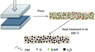
In this work, we have designed a carbon matrix supported Li–Si alloy anode, which is prepared by an easy pressing and heat-treatment process as shown in Fig. 1. When combined with a S@pPAN cathode, the full cell shows excellent long-term cycling performance under high capacity and no dendrite risk. This study pushes the development of high capacity cell systems towards potential application.
Results and discussion
Fig. 2a and b show the photo images of the pressed Li–Si composite and heat-treated alloy electrodes, which are free-standing with a certain mechanical strength. The heat-treatment made its color slightly lighter. The XRD patterns of Si powder and the heat-treated Li–Si alloy electrode are shown as in Fig. 2c, in which the characteristic peaks of Si disappeared after heat treatment. The main peaks of the Li–Si alloy electrode could be indexed to a Li21Si5 and Li21Si8 phase. A small peak located at ∼33° indicates a small amount of Li2O. Fig. S1† shows the morphologies of stable lithium metal powder (SLMP), Si powder and CNF. The SLMP and Si powders possess a spherical particle shape with diameters of 20–40 μm and ∼50 nm, respectively. The CNF shows a diameter of 50–70 nm. The initial discharge capacity of CNF is ∼800 mA h g−1 and the stable capacity is ∼150 mA h g−1 (Fig. S2†). Thus the weight ratio of Si to SLMP was optimized to 1.5![[thin space (1/6-em)]](https://www.rsc.org/images/entities/char_2009.gif) :
:![[thin space (1/6-em)]](https://www.rsc.org/images/entities/char_2009.gif) 1 to compensate for the Li loss during the heating process and irreversible capacity of CNF.
1 to compensate for the Li loss during the heating process and irreversible capacity of CNF.
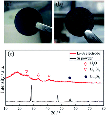 | ||
| Fig. 2 The photo images of a fresh pressed Li–Si–CNF composite (a) and a heat treated Li–Si alloy electrode (b), and the XRD patterns of Si powder and the Li–Si alloy electrode (c). | ||
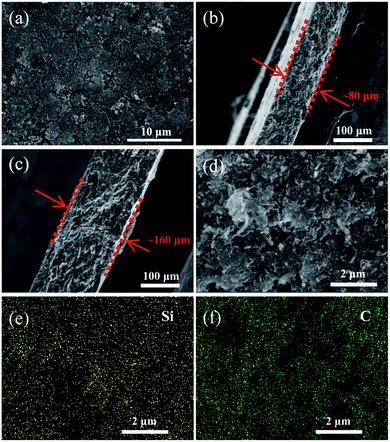
As shown in Fig. 3a, the surface of the heat-treated Li–Si electrode (60 wt% Li–Si) is even with some pores. The cross-sectional view images of the Li–Si alloy electrodes indicate the existence of many small holes (or voids) inside the electrodes (Fig. 3b–c). The thicknesses of the electrodes are ∼80 μm and ∼160 μm, respectively, corresponding to different areal capacities. Fig. 3d–f show that the Li–Si alloy particles are embedded homogeneously in the CNF matrix. The X-ray photoelectron spectrum (XPS) of the Li–Si electrode in Fig. S3a† identifies C, O and Li on the electrode surface, but without any Si peak (Fig. S3b†). This could be attributed to the oxidized layer on the surface, including Li2O and Li2CO3 (∼290 eV) as indicated in Fig. S3c.† For the Li–Si electrode without heat treatment, violent side-reactions took place as the electrode was brought into contact with the electrolyte due to the large surface area and high reactivity without sufficient surface passivation from the above oxidized layer.
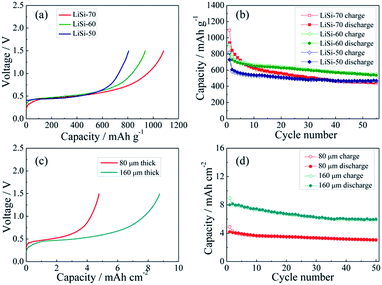
The electrochemical performance of the Li–Si electrodes was tested with half cells using Li metal as the counter electrode. The initial charging curves of the Li–Si electrodes are shown in Fig. 4a. The initial charging capacity could represent the Li storage capacity of the electrodes. The three electrodes with different Li–Si alloy contents are charged to 1.5 V at 100 mA g−1 and all electrodes show a long plateau at ∼0.4 V, and the capacities calculated from the total weight of the electrodes are 807, 938 and 1082 mA h g−1, corresponding to 50, 60 and 70 wt% alloy content. Fig. 4b shows the cycling performance of the alloy electrodes under near 100% DOD, where the electrodes containing 50% and 60% alloy possess good cycling performance and the capacity retentions after 55 cycles are 77% and 75%, respectively. Although the electrode containing 70% alloy delivers a higher initial charging capacity, its cycling performance is inferior. This might be ascribed to the instability of the electrode structure. When the alloy content is larger than 70%, a stable free-standing electrode cannot be fabricated. To balance both the capacity and cycling stability, the electrode with 60% alloy is adopted for further investigation. As shown in Fig. 4c, the areal capacities of the alloy electrodes with thicknesses of 80 μm and 160 μm are ∼4.5 and ∼9 mA h cm−2, respectively. The thinner electrode presents slightly better cycling stability (Fig. 4d). In addition, the cycling behavior of the Li–Si electrode (60 wt% alloy and a total capacity of ∼4.5 mA h cm−2) under a limited capacity of 1 mA h cm−2 has also been examined. As shown in Fig. S4,† the quite stable charge and discharge voltage trends in the range of 0.1–0.4 V indicate the high reversibility of lithiation and delithiation.
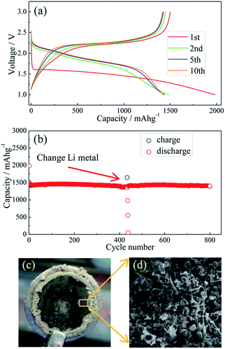
Li metal and Li–Si alloy anodes have been coupled respectively with a S@pPAN cathode to form coin cells and their cycling behaviors have been evaluated. As shown in Fig. 5a, the initial discharge/charge capacities of the Li/S@pPAN cell are 1985 mA h g−1 and 1496 mA h g−1, respectively, indicating a high utilization of sulfur. The first discharge plateau is at ∼1.5 V, but the voltage plateau gradually shifts upward to ∼2.0 V in the following cycles after the initial S@pPAN activation. Fig. 5b shows that the Li/S@pPAN cell could cycle more than 400 times without capacity decay, indicating the ultrahigh stability of the S@pPAN cathode. However, during the 434th cycle, the cell could not be charged to 3.0 V and cell failure occurred.
The cycled cell was disassembled in a glovebox and the dark grey surface of the Li metal was observed (Fig. 5c). The SEM image in Fig. 5d further reveals the Li morphology of rods and dendrites and the severe pulverization. After renewing the Li anode and adding fresh electrolyte, the Li/S@pPAN cell could be further cycled to 800 times without significant capacity fade (Fig. 5b). Thus, it can be concluded that decay of the Li metal anode and electrolyte exhaustion should be the main constraints for the long-term cycling of the Li/S@pPAN battery.
Substituting the Li metal anode with an alloy-type anode could be an effective method to address the dendrite growth and other problems. Comparing the normalized charging/discharging curves of S@pPAN and Li–Si alloy electrodes in Fig. 6, it can be inferred that a full cell using the Li–Si anode and S@pPAN cathode could achieve a ∼1.5 V discharging plateau theoretically. In order to increase the cell discharging voltage, the capacity of the anode should be higher than that of the cathode to permit Li extraction from the Li-rich alloy phase (i.e. possibly low anode de-lithiation potential). In addition, limiting the de-lithiation depth of the Li–Si electrode can improve its electrochemical reversibility as shown in Fig. S4.† With the capacity ratios of anode to cathode of 2![[thin space (1/6-em)]](https://www.rsc.org/images/entities/char_2009.gif) :
:![[thin space (1/6-em)]](https://www.rsc.org/images/entities/char_2009.gif) 1 and 4
1 and 4![[thin space (1/6-em)]](https://www.rsc.org/images/entities/char_2009.gif) :
:![[thin space (1/6-em)]](https://www.rsc.org/images/entities/char_2009.gif) 1, the terminal discharge voltage of the full cell could reach 0.4 V or 0.6 V (Fig. 6b and c). However, it should be mentioned that a high capacity ratio of anode to cathode will reduce the cell energy density significantly. The practical capacity ratio in the cell design should balance the voltage output, energy density and cycling performance. In the following tests of full cells, the capacity ratio of ∼4
1, the terminal discharge voltage of the full cell could reach 0.4 V or 0.6 V (Fig. 6b and c). However, it should be mentioned that a high capacity ratio of anode to cathode will reduce the cell energy density significantly. The practical capacity ratio in the cell design should balance the voltage output, energy density and cycling performance. In the following tests of full cells, the capacity ratio of ∼4![[thin space (1/6-em)]](https://www.rsc.org/images/entities/char_2009.gif) :
:![[thin space (1/6-em)]](https://www.rsc.org/images/entities/char_2009.gif) 1 is adopted for a possibly high voltage output. Cyclic voltammetry (CV) of Li/S@pPAN and Li–Si/S@pPAN cells is compared in Fig. S5.† For the Li/S@pPAN cell, the initial cathodic peak at ∼1.1 V could be ascribed to the activation of S@pPAN and the formation of a solid electrolyte interphase.35,38,63 Thus, the initial coulombic efficiency is ∼75%, which is consistent with the result in Fig. 5a. After the first cycle, the anodic peak at ∼2.4 V and cathodic peak at ∼1.8 V become stable. As for the Li–Si/S@pPAN cell, the initial cathodic peak shifts to ∼1 V, and the following anodic/cathodic peaks are stable at ∼2.2 V/∼1.5 V. The well-overlapped curves for the 2nd and 3rd cycles indicate excellent electrochemical reversibility of the Li–Si/S@pPAN cell.
1 is adopted for a possibly high voltage output. Cyclic voltammetry (CV) of Li/S@pPAN and Li–Si/S@pPAN cells is compared in Fig. S5.† For the Li/S@pPAN cell, the initial cathodic peak at ∼1.1 V could be ascribed to the activation of S@pPAN and the formation of a solid electrolyte interphase.35,38,63 Thus, the initial coulombic efficiency is ∼75%, which is consistent with the result in Fig. 5a. After the first cycle, the anodic peak at ∼2.4 V and cathodic peak at ∼1.8 V become stable. As for the Li–Si/S@pPAN cell, the initial cathodic peak shifts to ∼1 V, and the following anodic/cathodic peaks are stable at ∼2.2 V/∼1.5 V. The well-overlapped curves for the 2nd and 3rd cycles indicate excellent electrochemical reversibility of the Li–Si/S@pPAN cell.
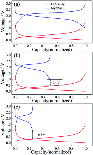 | ||
Fig. 6 The normalized charge/discharge curves of the Li–S@pPAN cell (1C) and Li–Si alloy electrode (100 mA g−1) with anode to cathode capacity ratios of 1![[thin space (1/6-em)]](https://www.rsc.org/images/entities/char_2009.gif) : :![[thin space (1/6-em)]](https://www.rsc.org/images/entities/char_2009.gif) 1 (a), 2 1 (a), 2![[thin space (1/6-em)]](https://www.rsc.org/images/entities/char_2009.gif) : :![[thin space (1/6-em)]](https://www.rsc.org/images/entities/char_2009.gif) 1 (b) and 4 1 (b) and 4![[thin space (1/6-em)]](https://www.rsc.org/images/entities/char_2009.gif) : :![[thin space (1/6-em)]](https://www.rsc.org/images/entities/char_2009.gif) 1 (c). 1 (c). | ||
The half-cell test shows that the initial charging capacity of the Li–Si anode is larger than its discharge capacity (Fig. S6†). The excess capacity could compensate for the capacity loss of S@pPAN during the initial cycle. Fig. 7a shows the charge/discharge curves of the Li–Si/S@pPAN cell for the initial 5 cycles at 1C (1C = 1675 mA g−1) from 0.6 V to 2.8 V. The 1st cycle efficiency is 76.3%, slightly higher than that of the Li/S@pPAN cell (75.3%). The first discharge plateau is at ∼1.25 V, slightly lower than that of the Li/S@pPAN cell. During the following cycles, the discharge plateau shifts to a stable plateau at ∼1.7 V. Thus, a lithium ion cell system with lithium ions shuttling between the anode and cathode has been successfully constructed. As shown in Fig. 7b, the Li–Si/S@pPAN cell possesses exceptional rate capability. When the current rate rises from 0.1C to 3C, the capacity declines from ca. 1450 to ca. 1170 mA h g−1 with a loss of only 19.3%. Moreover, the voltage polarization of the cell is acceptable even with a high rate of 3C (Fig. 7c). The cycling performance of the Li–Si/S@pPAN cell at 1C is shown in Fig. 7d. The initial discharge capacity is 1398 mA h g−1, and after 1000 cycles it is 1258 mA h g−1, corresponding to a capacity retention of ∼90%. Fig. 7e further exhibits the long-term cycling behavior at 3C. Even after 3000 cycles a capacity of 1075 mA h g−1 can be retained with an average fading rate of 0.03% per cycle. It should be mentioned that the coulombic efficiency approaches 99.8% except the first cycle for both 1C and 3C. The high reversibility of the Li–Si/S@pPAN cell should be ascribed to the stable S@pPAN and Li–Si electrode structures and their respective interfacial properties. The Li–Si/S@pPAN cell cycled 1000 times at 1C was disassembled in a glovebox. After washing with DMC and natural drying, it could be noticed that the Li–Si anode retained its good integrity without any pulverization, as shown in Fig. S7a.† The morphology of the cycled anode was further observed with SEM equipment. Fig. S7b and c† demonstrate the smooth electrode surface without obvious cracks and dissociated large particles. High loading sulfur electrodes (∼4.5 mA h cm−2) have also been tested in combination with Li metal and Li–Si alloy anodes (∼160 μm thickness, ∼9 mA h cm−2). Fig. S8† shows that the Li–Si/S@pPAN cell can retain a discharge capacity of ∼4.3 mA h cm−2 at 0.5C, but it encountered a short circuit after 113 cycles because of the existence of Li dendrites. After renewing the Li metal anode, it could be brought back to the normal state (Fig. S8b†). However, when paired with a Li–Si alloy anode, the S@pPAN cathode could be cycled more than 200 times with a capacity fading rate of 0.13% per cycle (Fig. S9b†).
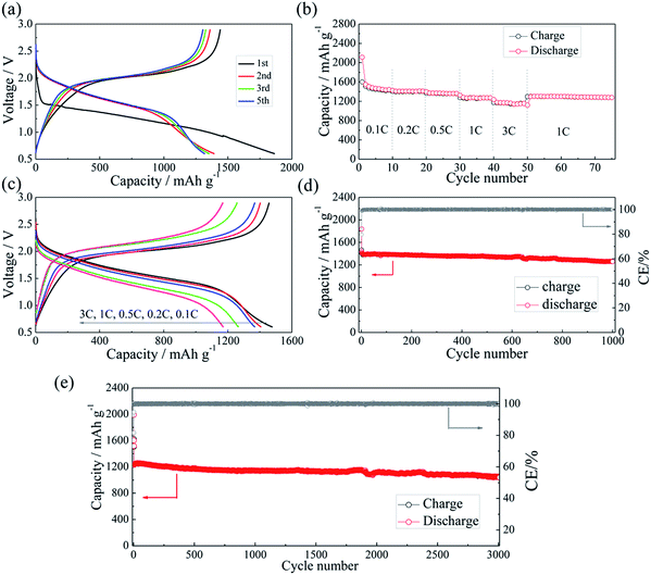 | ||
| Fig. 7 The charge/discharge curves of the Li–Si/S@pPAN cell from 0.6 V to 2.8 V at 1C (a), the rate capability (b and c) and the cycling performance of the full cell at 1C (d) and 3C (e). | ||
The Nyquist plots of Li/S@pPAN and Li–Si/S@pPAN cells in the charging state after different cycles at 0.5C are shown in Fig. S10.† For the Li/S@pPAN cell, two semicircles emerged in the high frequency region after the first cycle and gradually enlarged during the cycling. They could be mainly attributed to the resistances of the SEI and interfacial reaction on the Li metal (Fig. S10a†). In contrast, for the Li–Si/S@pPAN cell, the semicircles are much smaller and relatively stable during cycling (Fig. S10b†), indicating low and stable interfacial resistances during cycling.
Conclusions
In summary, a stable lithium-rich Li–Si anode supported by a CNF matrix has been successfully prepared and applied in a lithium-ion–sulfur battery system. Compared with a lithium metal anode, it exhibits no pulverization and no dendrite formation during long cycling. The Li–Si/S@pPAN battery exhibits excellent cycling performance with a negligible capacity fading rate of 0.01% per cycle for 1000 cycles at 1C and 0.03% per cycle for 3000 cycles at 3C. The flexible carbon matrix with its content of 40 wt% buffers the volume change of lithium-rich alloys and guarantees the integrity and sufficient conductivity of the electrode, while the S@pPAN cathode avoids the shuttle effect in carbonate electrolytes. The synergistic effects of these factors endow the full battery with ultra-long cycle life towards practical application.Conflicts of interest
There are no conflicts to declare.Acknowledgements
This work was supported by the National Key Basic Research Program of China (No. 2014CB932303) and the National Natural Science Foundation of China (No. 21773154).Notes and references
- A. Manthiram, Y. Fu, S. H. Chung, C. Zu and Y. S. Su, Chem. Rev., 2014, 114, 11751–11787 CrossRef CAS PubMed.
- X. Ji, K. T. Lee and L. F. Nazar, Nat. Mater., 2009, 8, 500–506 CrossRef CAS PubMed.
- Y. X. Yin, S. Xin, Y. G. Guo and L. J. Wan, Angew. Chem., 2013, 52, 13186–13200 CrossRef CAS PubMed.
- Y. Yang, G. Zheng and Y. Cui, Chem. Soc. Rev., 2013, 42, 3018–3032 RSC.
- Y. Son, J.-S. Lee, Y. Son, J.-H. Jang and J. Cho, Adv. Energy Mater., 2015, 5, 1500110 CrossRef.
- W. Li, H. Yao, K. Yan, G. Zheng, Z. Liang, Y. M. Chiang and Y. Cui, Nat. Commun., 2015, 6, 7436 CrossRef CAS PubMed.
- N. W. Li, Y. Shi, Y. X. Yin, X. X. Zeng, J. Y. Li, C. J. Li, L. J. Wan, R. Wen and Y. G. Guo, Angew. Chem., 2018, 57, 1505–1509 CrossRef CAS PubMed.
- X. B. Cheng, T. Z. Hou, R. Zhang, H. J. Peng, C. Z. Zhao, J. Q. Huang and Q. Zhang, Adv. Mater., 2016, 28, 2888–2895 CrossRef CAS PubMed.
- N. Jayaprakash, J. Shen, S. S. Moganty, A. Corona and L. A. Archer, Angew. Chem., 2011, 50, 5904–5908 CrossRef CAS PubMed.
- S. Xin, L. Gu, N. H. Zhao, Y. X. Yin, L. J. Zhou, Y. G. Guo and L. J. Wan, J. Am. Chem. Soc., 2012, 134, 18510–18513 CrossRef CAS PubMed.
- F. Pei, L. Lin, D. Ou, Z. Zheng, S. Mo, X. Fang and N. Zheng, Nat. Commun., 2017, 8, 482 CrossRef PubMed.
- Z. Li, Y. Jiang, L. Yuan, Z. Yi, C. Wu, Y. Liu, P. Strasser and Y. Huang, ACS Nano, 2014, 8, 9295 CrossRef CAS PubMed.
- G. He, S. Evers, X. Liang, M. Cuisinier, A. Garsuch and L. F. Nazar, ACS Nano, 2013, 7, 10920 CrossRef CAS PubMed.
- X. Liu, J. Q. Huang, Q. Zhang and L. Mai, Adv. Mater., 2017, 29, 1601759 CrossRef PubMed.
- Z. Li, J. Zhang, B. Guan, D. Wang, L. M. Liu and X. W. Lou, Nat. Commun., 2016, 7, 13065 CrossRef CAS PubMed.
- Q. Pang, D. Kundu, M. Cuisinier and L. F. Nazar, Nat. Commun., 2014, 5, 4759 CrossRef CAS PubMed.
- X. Liang, C. Hart, Q. Pang, A. Garsuch, T. Weiss and L. F. Nazar, Nat. Commun., 2015, 6, 5682 CrossRef PubMed.
- Z. Yuan, H. J. Peng, T. Z. Hou, J. Q. Huang, C. M. Chen, D. W. Wang, X. B. Cheng, F. Wei and Q. Zhang, Nano Lett., 2016, 16, 519–527 CrossRef CAS PubMed.
- Z. Sun, J. Zhang, L. Yin, G. Hu, R. Fang, H. M. Cheng and F. Li, Nat. Commun., 2017, 8, 14627 CrossRef PubMed.
- L. Hu, C. Dai, J. M. Lim, Y. Chen, X. Lian, M. Wang, Y. Li, P. Xiao, G. Henkelman and M. Xu, Chem. Sci., 2018, 9, 666–675 RSC.
- H. Wang, W. Zhang, J. Xu and Z. Guo, Adv. Funct. Mater., 2018, 1707520 CrossRef.
- Y.-J. Li, J.-M. Fan, M.-S. Zheng and Q.-F. Dong, Energy Environ. Sci., 2016, 9, 1998–2004 RSC.
- Y. Q. Lu, Y. J. Wu, T. Sheng, X. X. Peng, Z. G. Gao, S. J. Zhang, L. Deng, R. Nie, J. Swiatowska, J. T. Li, Y. Zhou, L. Huang, X. D. Zhou and S. G. Sun, ACS Appl. Mater. Interfaces, 2018, 10, 13499–13508 CrossRef CAS PubMed.
- J. C. Ye, J. J. Chen, R. M. Yuan, D. R. Deng, M. S. Zheng, L. Cronin and Q. F. Dong, J. Am. Chem. Soc., 2018, 140, 3134–3138 CrossRef CAS PubMed.
- F. Pei, L. Lin, A. Fu, S. Mo, D. Ou, X. Fang and N. Zheng, Joule, 2018, 2, 323–336 CrossRef CAS.
- G. Ma, Z. Wen, Q. Wang, C. Shen, P. Peng, J. Jin and X. Wu, J. Power Sources, 2015, 273, 511–516 CrossRef CAS.
- H. Wang, W. Zhang, H. Liu and Z. Guo, Angew. Chem., 2016, 55, 3992–3996 CrossRef CAS PubMed.
- S. Bai, X. Liu, K. Zhu, S. Wu and H. Zhou, Nat. Energy, 2016, 1, 16094 CrossRef CAS.
- W. Hu, Y. Hirota, Y. Zhu, N. Yoshida, M. Miyamoto, T. Zheng and N. Nishiyama, ChemSusChem, 2017, 10, 3557 CrossRef CAS PubMed.
- G. Xu, Q. B. Yan, S. Wang, A. Kushima, P. Bai, K. Liu, X. Zhang, Z. Tang and J. Li, Chem. Sci., 2017, 8, 6619–6625 RSC.
- K. Fu, Y. Gong, G. T. Hitz, D. W. McOwen, Y. Li, S. Xu, Y. Wen, L. Zhang, C. Wang, G. Pastel, J. Dai, B. Liu, H. Xie, Y. Yao, E. D. Wachsman and L. Hu, Energy Environ. Sci., 2017, 10, 1568–1575 RSC.
- H. Qu, J. Zhang, A. Du, B. Chen, J. Chai, N. Xue, L. Wang, L. Qiao, C. Wang, X. Zang, J. Yang, X. Wang and G. Cui, Adv. Sci., 2018, 5, 1700503 CrossRef PubMed.
- J. Wang, J. Yang, J. Xie and N. Xu, Adv. Mater., 2002, 14, 963 CrossRef CAS.
- J. Wang, J. Yang, C. Wan, J. Xie and N. Xu, Adv. Funct. Mater., 2003, 13, 487 CrossRef CAS.
- S. Wei, L. Ma, K. E. Hendrickson, Z. Tu and L. A. Archer, J. Am. Chem. Soc., 2015, 137, 12143–12152 CrossRef CAS PubMed.
- Y. Liu, A. K. Haridas, K.-K. Cho, Y. Lee and J.-H. Ahn, J. Phys. Chem. C, 2017, 121, 26172–26179 CrossRef.
- H. M. Kim, J. Y. Hwang, D. Aurbach and Y. K. Sun, J. Phys. Chem. Lett., 2017, 8, 5331–5337 CrossRef CAS PubMed.
- Z.-Q. Jin, Y.-G. Liu, W.-K. Wang, A.-B. Wang, B.-W. Hu, M. Shen, T. Gao, P.-C. Zhao and Y.-S. Yang, Energy Storage Materials, 2018, 14, 272–278 CrossRef.
- D. Lin, Y. Liu, Z. Liang, H. W. Lee, J. Sun, H. Wang, K. Yan, J. Xie and Y. Cui, Nat. Nanotechnol., 2016, 11, 626–632 CrossRef CAS PubMed.
- Y. Wang, Y. Shen, Z. Du, X. Zhang, K. Wang, H. Zhang, T. Kang, F. Guo, C. Liu, X. Wu, W. Lu and L. Chen, J. Mater. Chem. A, 2017, 5, 23434–23439 RSC.
- Y. Lu, Z. Tu and L. A. Archer, Nat. Mater., 2014, 13, 961–969 CrossRef CAS PubMed.
- X. Ren, Y. Zhang, M. H. Engelhard, Q. Li, J.-G. Zhang and W. Xu, ACS Energy Lett., 2017, 3, 14–19 CrossRef.
- F. Ding, W. Xu, G. L. Graff, J. Zhang, M. L. Sushko, X. Chen, Y. Shao, M. H. Engelhard, Z. Nie, J. Xiao, X. Liu, P. V. Sushko, J. Liu and J. G. Zhang, J. Am. Chem. Soc., 2013, 135, 4450–4456 CrossRef CAS PubMed.
- Z. Xu, J. Wang, J. Yang, X. Miao, R. Chen, J. Qian and R. Miao, Angew. Chem., 2016, 55, 10372–10375 CrossRef CAS PubMed.
- G. Zheng, C. Wang, A. Pei, J. Lopez, F. Shi, Z. Chen, A. D. Sendek, H.-W. Lee, Z. Lu, H. Schneider, M. M. Safont-Sempere, S. Chu, Z. Bao and Y. Cui, ACS Energy Lett., 2016, 1, 1247–1255 CrossRef CAS.
- H. Ye, S. Xin, Y.-X. Yin and Y.-G. Guo, Adv. Energy Mater., 2017, 7, 1700530 CrossRef.
- J. Luo, R. C. Lee, J. T. Jin, Y. T. Weng, C. C. Fang and N. L. Wu, Chem. Commun., 2017, 53, 963–966 RSC.
- H. Wu, Y. Cao, L. Geng and C. Wang, Chem. Mater., 2017, 29, 3572–3579 CrossRef CAS.
- E. Kazyak, K. N. Wood and N. P. Dasgupta, Chem. Mater., 2015, 27, 6457–6462 CrossRef CAS.
- B. Liu, W. Xu, J. Tao, P. Yan, J. Zheng, M. H. Engelhard, D. Lu, C. Wang and J.-G. Zhang, Adv. Energy Mater., 2018, 8, 1702340 CrossRef.
- Y. Li, Y. Sun, A. Pei, K. Chen, A. Vailionis, Y. Li, G. Zheng, J. Sun and Y. Cui, ACS Cent. Sci., 2018, 4, 97–104 CrossRef CAS PubMed.
- H. Wu, Y. Cao, H. Su and C. Wang, Angew. Chem., 2018, 57, 1361–1365 CrossRef CAS PubMed.
- J. Ju, Y. Wang, B. Chen, J. Ma, S. Dong, J. Chai, H. Qu, L. Cui, X. Wu and G. Cui, ACS Appl. Mater. Interfaces, 2018, 10, 13588–13597 CrossRef CAS PubMed.
- L. Yue, J. Ma, J. Zhang, J. Zhao, S. Dong, Z. Liu, G. Cui and L. Chen, Energy Storage Materials, 2016, 5, 139–164 CrossRef.
- Y. Wu, T. Momma, T. Yokoshima, H. Nara and T. Osaka, J. Power Sources, 2018, 388, 5–10 CrossRef CAS.
- J. Hassoun and B. Scrosati, Angew. Chem., 2010, 49, 2371–2374 CrossRef CAS PubMed.
- M. Weinberger and M. Wohlfahrt-Mehrens, Electrochim. Acta, 2016, 191, 124–132 CrossRef CAS.
- M. Hagen, E. Quiroga-González, S. Dörfler, G. Fahrer, J. Tübke, M. J. Hoffmann, H. Althues, R. Speck, M. Krampfert, S. Kaskel and H. Föll, J. Power Sources, 2014, 248, 1058–1066 CrossRef CAS.
- J. Zhao, G. Zhou, K. Yan, J. Xie, Y. Li, L. Liao, Y. Jin, K. Liu, P. C. Hsu, J. Wang, H. M. Cheng and Y. Cui, Nat. Nanotechnol., 2017, 12, 993–999 CrossRef CAS PubMed.
- K. Zhang, L. Wang, Z. Hu, F. Cheng and J. Chen, Sci. Rep., 2014, 4, 6467 CrossRef CAS PubMed.
- T. Zhang, J. Yang, J. Zhu, J. Zhou, Z. Xu, J. Wang, F. Qiu and P. He, Chem. Commun., 2018, 54, 1069–1072 RSC.
- J. Hassoun, J. Kim, D.-J. Lee, H.-G. Jung, S.-M. Lee, Y.-K. Sun and B. Scrosati, J. Power Sources, 2012, 202, 308–313 CrossRef CAS.
- J. Sun, Q. Zeng, R. Lv, W. Lv, Q.-H. Yang, R. Amal and D.-W. Wang, Energy Storage Materials, 2018, 15, 209–217 CrossRef.
Footnote |
| † Electronic supplementary information (ESI) available. See DOI: 10.1039/c8sc02897d |
| This journal is © The Royal Society of Chemistry 2018 |

