3D interconnected porous carbon nanosheets/carbon nanotubes as a polysulfide reservoir for high performance lithium–sulfur batteries†
Wu
Yang
ab,
Wang
Yang
b,
Ailing
Song
b,
Gang
Sun
b and
Guangjie
Shao
 *ab
*ab
aState Key Laboratory of Metastable Materials Science and Technology, Yanshan University, Qinhuangdao 066004, China. E-mail: shaoguangjie@ysu.edu.cn; Fax: +0086-335-8059878; Tel: +0086-335-8061569
bHebei Key Laboratory of Applied Chemistry, College of Environmental and Chemical Engineering, Yanshan University, Qinhuangdao 066004, China
First published on 1st December 2017
Abstract
Carbon materials have attracted considerable attention as the hosts for lithium–sulfur batteries, especially the 3D structural carbon matrix. Herein, novel 3D interconnected porous carbon nanosheets/carbon nanotubes (denoted as PC/CNT) as a polysulfide reservoir are synthesized by a simple one-pot pyrolysis method. In the designed hybrid carbon matrix, porous carbon nanosheets exhibit hierarchical porous structures for high sulfur loading and effectively strengthen the physical confinement to trap soluble polysulfides, while carbon nanotubes provide a highly robust conductive pathway which can facilitate electron transport and maintain structural integrity. Moreover, the 3D interconnected structure combining 1D carbon nanotubes and 2D porous carbon nanosheets is beneficial for rapid electrical/ionic transport and favorable electrolyte infiltration. As a result, the S-PC/CNT composite exhibits outstanding electrochemical performance, with a high active-sulfur utilization, high specific capacity (1485.4, 1300.3 and 1138 mA h g−1 at 0.5, 1 and 2 C, respectively), superior cycling stability (only 0.1% capacity decay per cycle over 400 cycles at 2 C) and excellent rate capability (the reversible capacity of 749 mA h g−1 even at 4 C).
Introduction
With the ever-increasing demand for energy storage in portable electronic devices and electric vehicles, it is imperative to explore advanced energy storage devices with long cycling stability and high energy density, which are expected to replace the conventional lithium-ion batteries (LIB).1,2 Of the various alternatives, lithium–sulfur batteries (LSB) have attracted extensive attention as a competitive candidate for energy conversion and storage applications due to their exceptional theoretical energy density of 2600 W h kg−1, which is over five times greater than those of state-of-the-art LIB.3–8 More importantly, sulfur has the advantages, over current cathode materials, of natural abundance, low cost, and non-toxicity and theoretically offers a high specific capacity (1675 mA h g−1).9,10 However, the practical application of LSB is still plagued by several technical challenges, including rapid capacity decay, poor cycling stability and inferior rate capability. More specifically, the insulating nature of elemental sulfur and its final discharge products (Li2S/Li2S2), severe volume changes (∼80%) during cycling, and the “shuttle effect” caused by soluble lithium polysulfides (LiPS) have always been the three stumbling blocks of LSB for practical application.7–14Aiming to address the abovementioned issues associated with LSB, numerous strategies, including novel nanostructured sulfur cathodes,7–9,14–18 protected lithium metal anodes,19,20 advanced electrolytes,21–23 and modified separators or interlayers,10,24–27 have been proposed for improving the electrochemical performance of LSB. Carbon materials have been proved to be the most promising hosts for sulfur cathodes, which can improve the electronic conductivity of sulfur cathodes, adsorb soluble LiPS, and accommodate volumetric expansion.9,27–29 Carbon nanotubes (CNTs), a classic 1D carbon material, have been extensively used as the host for sulfur accommodation, owing to their superiority in excellent electronic conductivity and mechanical strength.27–32 Moreover, CNTs possess a large aspect ratio and assemble into an interconnected conductive network, providing an efficient conductive pathway for electron transport.33 Nevertheless, the low specific surface area (typically <200 m2 g−1) and the poor porosity of CNTs not only accommodate the low sulfur content in S-CNT composites, but also exert poor LiPS trapping. 2D carbon materials, such as porous carbon nanosheets (PCNs) and graphene nanosheets (GNs), are also noticeable alternatives as the host for sulfur cathodes. The porous structure and strong adsorption ability of PCNs benefit the high sulfur loading and restrain the dissolution of LiPS into the electrolyte, leading to the high active-sulfur utilization and good cycling stability. However, the rate capability of the sulfur cathode has not improved greatly, which is ascribed to the relatively low electronic conductivity derived from the sp3-hybridized C–C bond of amorphous carbon.32,33 Furthermore, both 1D and 2D carbon materials are easy to aggregate, leading to the reduced effective specific surface area and available space.
Consequently, it is necessary to design hybrid carbon materials that integrate porous carbon materials with conductive carbon materials as host materials for sulfur cathodes.31–33 Furthermore, combining 1D CNTs with 2D carbon materials is beneficial to construct a 3D structural carbon matrix, which can be endowed with an overwhelming advantage in compositing sulfur due to the higher dimensional structure.29,30 Recently, hybrid carbon materials with a 3D hierarchical structure combining 1D CNTs and 2D GNs have attracted considerable attention for LSB.29,32,34 However, the synthetic methods of the above hybrid carbon materials are relatively intricate and uncontrollable. As to this aspect, researchers have been developing stable and applicable carbon materials with appropriate pore structures as a one carbon component. Not surprisingly, such a series of hybrid carbon materials has been designed for stable sulfur accommodation, for instance, carbon black/multi-walled CNT hybrid structures via ball-mill mixing,30 CNT embedded biomass-derived hierarchically porous carbon hybrid structures by a simple carbonization method,35 and hierarchically porous carbon/CNT hybrid structures through hard template techniques.36 It is noted that these hybrid cathodes exhibit an enhanced electrochemical performance owing to the synergistic effect of the hierarchically porous carbon and CNTs. Nevertheless, the above hybrid carbon materials with slow charge transfer and poor electrolyte infiltration cannot be called 3D carbon materials in the nanoscale attributed to the bulk porous carbon particles. Thus, 2D PCNs might be an optimal choice to construct an appropriate 3D nanostructure carbon matrix for LSB.
Based on the aforementioned consideration, we propose a facile and scalable strategy to prepare 3D interconnected porous carbon nanosheets/carbon nanotubes (denoted PC/CNT) as the host for subsequent sulfur loading. After a simple one-pot pyrolysis process, the 3D interconnected structure tightly integrates PCNs and CNTs, which are very promising in preparing desirable sulfur cathodes. Notably, it offers several structural advantages: (i) abundant hierarchical pores stemming from PCNs can significantly increase sulfur loading and effectively strengthen the physical confinement to trap LiPS due to strong adsorption; (ii) a highly robust conductive pathway for electron transport originating from CNTs ensures good electrical conductivity and structural integrity; and (iii) 3D interconnected hierarchical porous structures and conductive networks provide more pathways for rapid electrical/ionic transport and accelerate electrolyte infiltration. As expected, when serving as the host for the sulfur cathode, the S-PC/CNT composite exhibits superior cycling stability and excellent rate capability.
Experimental section
Preparation of PC/CNT
To obtain the PC/CNT matrix, sodium citrate was first treated by drying and ball-milling as reported previously.37 In a typical synthesis, processed sodium citrate (5 g) and CNTs (0.3 g) were ball-milled for 1 h, and the ground powder was put in a porcelain boat and annealed in a tube furnace at 850 °C with a heating rate of 5 °C min−1 under a nitrogen atmosphere for 1 h. After that, the resulting material was cooled to room temperature and successively washed with 10 wt% HCl and abundant deionized water several times. Finally, the desired composite was obtained by drying at 80 °C in an oven overnight. Similarly, the PC sample was prepared by directly annealing sodium citrate without adding CNTs.Preparation of S-PC/CNT
The S-PC/CNT composites were prepared via a typical melt-diffusion method. Typically, the carbon matrix was mixed with different amounts of sulfur powder in a Teflon container, and then heated at 155 °C in an oven for 20 h under an argon atmosphere. After that, the product was heated at 200 °C for 2 h under an argon atmosphere in a tube furnace to remove the redundant sulfur outside. After cooling to room temperature, the as-prepared S-PC/CNT composites with different sulfur contents were obtained, and were labeled as S-PC/CNT (X), where the X refers to the weight ratios of sulfur and carbon. S-CNT and S-PC composites were also prepared with the same method. Note that the default sulfur/carbon ratio is 2![[thin space (1/6-em)]](https://www.rsc.org/images/entities/char_2009.gif) :
:![[thin space (1/6-em)]](https://www.rsc.org/images/entities/char_2009.gif) 1, if not specified.
1, if not specified.
Material characterization
The morphologies of all the samples were analyzed by scanning electron microscopy (FESEM, Hitachi S-4800, Japan) and high-resolution transmission electron microscopy (HRTEM, JEOL-2100F). Energy dispersive X-ray spectroscopy (EDS) analysis was performed on a Tecnai F20 scanning transmission electron microscope operated at 200 keV using an Oxford detector with a beam current of ∼1 nA. Raman spectroscopy measurements were conducted on a Horiva (Xplora Plus) system at an excitation wavelength of 532 nm with 0.1 mW Raman laser power on the sample. Elemental analysis was performed by X-ray photoelectron spectroscopy (XPS) with a Kratos XSAM-800 spectrometer with monochromatized Al Kα radiation. X-ray diffraction (XRD) patterns of the samples were recorded on a Rigaku Smart Lab X-ray diffractometer operated at 40 kV using Cu Kα radiation at a scan rate of 5° min−1. The actual sulfur content of the composites was determined by using a thermogravimetric analyzer (TGA, Pyris Diamond, PerkinElmer Thermal Analysis) from room temperature to 500 °C at a heating rate of 10 °C min−1 under a nitrogen atmosphere. Nitrogen adsorption–desorption isotherms and pore size distributions were obtained at 77 K using a Micromeritics V-Sorb 2800P analyzer. Pore size distribution (PSD) in the micropore range (<2 nm) was obtained by the Saito–Foley (SF) method, and pore size distribution in the larger range was obtained by the Barrett–Joyner–Halenda (BJH) method. Electric conductivity was measured using an ST2722-SZ semiconductor powder resistivity instrument.Electrochemical measurements
The working electrodes were prepared as follows: 80 wt% of active materials was combined with 10 wt% of acetylene black and 10 wt% of polyvinylidene fluoride (PVDF) binder in N-methyl-2-pyrrolidone (NMP). Then the resulting homogeneous slurry was blade cast onto an aluminum foil and dried at 60 °C for 12 h in a vacuum oven. The sulfur loading of the cathodes was controlled in the range of 1.2–1.5 mg cm−2. CR2025 coin cells were assembled with lithium foil as the reference/counter-electrode and the porous membrane (Celgard 2400) as the separator in an argon-filled glove box. The electrolyte was composed of lithium bis(trifluoromethanesulfonyl)imide (LiTFSI, 1.0 mol L−1) and lithium nitrate (LiNO3, 0.4 mol L−1) in a mixed solvent of 1,3-dioxolane (DOL) and 1,2-dimethoxyethane (DME) (volume ratio = 1![[thin space (1/6-em)]](https://www.rsc.org/images/entities/char_2009.gif) :
:![[thin space (1/6-em)]](https://www.rsc.org/images/entities/char_2009.gif) 1). For each electrode, 35–45 μL electrolyte was added in the coin cell and the electrolyte-to-sulfur ratio was fixed at 40 μL mg−1. Electrochemical measurements were performed on a LAND-CT2001A battery testing system (Wuhan, China). The cells were galvanostatically discharged and charged in a voltage range of 1.7–2.8 V at different current densities. The specific capacity values were calculated based on the mass of sulfur in the cathode. Cyclic voltammetry (CV) tests were conducted on a CHI660E electrochemical workstation (Shanghai, China) at a scan rate of 0.1 mV s−1. All the electrochemical tests were performed at 25 °C and all the potentials cited in this paper were referred to Li/Li+.
1). For each electrode, 35–45 μL electrolyte was added in the coin cell and the electrolyte-to-sulfur ratio was fixed at 40 μL mg−1. Electrochemical measurements were performed on a LAND-CT2001A battery testing system (Wuhan, China). The cells were galvanostatically discharged and charged in a voltage range of 1.7–2.8 V at different current densities. The specific capacity values were calculated based on the mass of sulfur in the cathode. Cyclic voltammetry (CV) tests were conducted on a CHI660E electrochemical workstation (Shanghai, China) at a scan rate of 0.1 mV s−1. All the electrochemical tests were performed at 25 °C and all the potentials cited in this paper were referred to Li/Li+.
Results and discussion
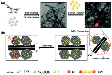
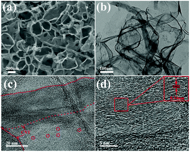
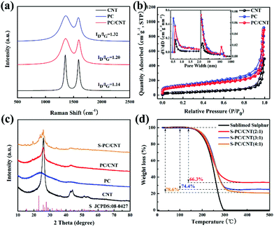
Fig. 1 schematically illustrates the synthetic process of the S-PC/CNT composite and the trapping mechanism of sulfur and polysulfides in the PC/CNT reservoir. As illustrated in Fig. 1(a), a traditional ball-milling method was first employed to mix the CNTs with sodium citrate, and then the mixture was subjected to a facile one-pot pyrolysis process, obtaining 3D interconnected PC/CNT. Comprehensibly, PCNs with abundant micropores and macropores were synthesized by a template-free method, where Na2CO3 formed in the carbonization process acts as the pore-foaming agent.37 And these stacked nanosheets exhibited a distinct 2D structure. After adding CNTs, the scaffolds shore up the porous carbon nanosheets and the 2D structures changed to 3D interconnected hierarchical porous structures.38,39 Subsequently, sulfur was impregnated into the PC/CNT matrix through a melt-diffusion method. Clearly, sulfur which mainly encapsulates into the abundant hierarchical pores of PCNs and CNTs provides a highly robust conductive pathway for electron transport, and the 3D interconnected structure combining 1D CNTs and 2D PCNs is beneficial for rapid electrical/ionic transport and favorable electrolyte infiltration. The mechanism of polysulfide trapping and the intriguing structural advantages of PC/CNT are demonstrated in Fig. 1(b). During the discharge process, PCNs with hierarchical porous structures can act as an ideal polysulfide reservoir, which strongly inhibits the dissolution of LiPS by physical confinement. Additionally, the interconnected conductive networks of CNTs enhance the overall electrical conductivity of the electrode and maintain the structural integrity.The morphology and structure of the as-prepared samples were investigated by SEM and TEM. The PC matrix from carbonized sodium citrate generally shows a crushed porous carbon shell like morphology as seen in Fig. S1,† which is composed of numerous collapsed carbon nanosheets with a thickness of about 10 nm (Fig. S2†). The commercial CNTs exhibit diameters around 20–30 nm and lengths up to several micrometers as shown in Fig. S1 and S2.† Quite intriguingly, the PC/CNT composite remains in its integrated porous carbon nanosheet structure supported by interconnected CNTs, as depicted in Fig. 2(a) and Fig. S3.† The TEM image in Fig. 2(b) also clearly confirms that CNTs are intertwined with PCNs to form a 3D interconnected structure, where the CNT scaffolds shore up the porous carbon nanosheets.38 It is further observed from Fig. 2(c) that CNTs are tightly surrounded by amorphous carbon, probably a compact junction covalently formed between PCNs and CNTs. Moreover, it is clear that some graphitized carbon (red circle in Fig. 2(c)) appears on the PCNs, implying that PCNs also possess a relatively high electric conductivity. Clearly, the aligned lattice fringes with an adjacent fringe spacing of 0.34 nm corresponding to the (002) planes of the graphitic carbon are readily observable in Fig. 2(d). This result agrees with an elevated ordering degree of PC/CNT, as presented by the appearance of diffraction peaks centered at around 26.0° and 43° in the XRD pattern of PC/CNT (Fig. 3(c)), corresponding to the periodically arranged (002) and (100) planes of the graphitic carbon.35,36 The overall ordering degree of PC/CNT can be further confirmed by the Raman spectra in Fig. 3(a), which shows two characteristic peaks of carbon at ∼1359 cm−1 (D band) and ∼1587 cm−1 (G band) related to the defective carbon and graphitic carbon, respectively. Typically, the intensity ratio of D and G bands (ID/IG) has always been used to evaluate the ordering degree of carbon.37,40 For the CNTs, the ID/IG ratio is as low as 1.12, indicating a highly ordered sp2 structure. From PC to PC/CNT, the ID/IG ratio decreases, which confirms an increased ordering degree upon CNT embedding, resulting in higher conductivity. Furthermore, the electric conductivities of CNT, PC, and PC/CNT were measured at 7 MPa (Table S1†). The values are 27.6, 15.5 and 19.8 S cm−1, respectively. The above results agree with the XRD and Raman data, suggesting that PC/CNT possess a high electric conductivity.
The pore structures of carbon samples were characterized by nitrogen adsorption/desorption measurements. As shown in Fig. 3(b), the isotherms of PC and PC/CNT exhibit the joint curve of type I and II, demonstrating the hierarchical porous structure composed of micropores and macropores. The commercial CNTs show typical type I isotherms, indicating the mere presence of micropores. The calculated Brunauer–Emmett–Teller (BET) surface areas of CNT, PC, and PC/CNT are 176, 616, and 572 m2 g−1, respectively. Upon CNT embedding, the specific surface area of PC/CNT certainly does not undergo a dramatic decline, suggesting the integrity of the 3D interconnected structure. The pore size distribution (the inset of Fig. 3(b)) of PC/CNT analyzed by the non-local density functional theory (NLDFT) method further reveals the existence of macropores with sizes centered at 135 nm and abundant micropores with an average size of 0.6 nm. In comparison with the PC matrix, the number of macropores significantly increases, implying integrated PCNs supported by interconnected CNTs, being well consistent with SEM and TEM observations in Fig. 2. In such a designed hybrid carbon matrix, the micropores can strongly restrain the dissolution/diffusion of LiPS and the macropores are beneficial to accommodate high sulfur loading.34–36 In addition, the 3D interconnected hierarchical structure with favorable conductive networks, which is constructed by using PCNs and CNTs, provides more pathways for rapid electrical/ionic transport and accelerates electrolyte infiltration enhancing the cycling stability and rate capability.40
Typically, sulfur is impregnated into the PC/CNT matrix by a melt-diffusion strategy, yielding the S-PC/CNT composites (Fig. 1). The XRD patterns of pure sulfur and S-PC/CNT with different sulfur loading were investigated to identify the crystallinity of sulfur shown in Fig. 3(c) and Fig. S4.† Similar to the patterns of PC/CNT, the S-PC/CNT composites exhibit diffraction peaks at around 26.0° and 43°, assigned to the graphitic carbon structure. However, no obvious diffraction peak for orthorhombic phase sulfur (JCPDS No. 08-0247) can be observed, confirming that most of the sulfur has successfully encapsulated into the abundant hierarchical pores of PC/CNT.28 With the increase in sulfur loading, sulfur exists in a crystalline state with sharp characteristic peaks (Fig. S4†). This result is well proved by SEM observations shown in Fig. S5,† where we can clearly see that a small amount of crystal sulfur appears on the surface of the matrix with higher sulfur loading. The sulfur content measured by TGA for the S-PC/CNT composites prepared with different ratios (2![[thin space (1/6-em)]](https://www.rsc.org/images/entities/char_2009.gif) :
:![[thin space (1/6-em)]](https://www.rsc.org/images/entities/char_2009.gif) 1, 3
1, 3![[thin space (1/6-em)]](https://www.rsc.org/images/entities/char_2009.gif) :
:![[thin space (1/6-em)]](https://www.rsc.org/images/entities/char_2009.gif) 1, 4
1, 4![[thin space (1/6-em)]](https://www.rsc.org/images/entities/char_2009.gif) :
:![[thin space (1/6-em)]](https://www.rsc.org/images/entities/char_2009.gif) 1) was 66.3, 74.4 and 78.6 wt%, respectively (Fig. 3(d)). It can be observed that pure sulfur vaporizing starts at around 150 °C and completes at around 300 °C. Interestingly, the S-PC/CNT composites exhibit a higher evaporation temperature, indicating the strong interaction between sulfur and PC/CNT.35
1) was 66.3, 74.4 and 78.6 wt%, respectively (Fig. 3(d)). It can be observed that pure sulfur vaporizing starts at around 150 °C and completes at around 300 °C. Interestingly, the S-PC/CNT composites exhibit a higher evaporation temperature, indicating the strong interaction between sulfur and PC/CNT.35
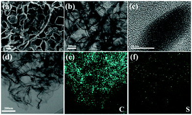
Fig. 4(a–c) show the morphology characterization of the S-PC/CNT composite. It can be seen that the S-PC/CNT composite still maintains the pristine carbon morphology after sulfur loading and no agglomerated sulfur particles are exposed on the surface of the matrix, providing further evidence that sulfur has successfully diffused into the PC/CNT matrix.35,36 Furthermore, amorphous sulfur dominates in the composite as observed in the HRTEM images (Fig. 4(c)), which agrees with the almost vanished diffraction peak of crystalline sulfur in the XRD patterns. To visually investigate the sulfur distribution in the carbon framework, the S-PC/CNT composite was analyzed by EDS elemental mapping. As shown in Fig. 4(d–f), sulfur exists in the PCN framework with a homogeneous distribution, signifying the successful accommodation of sulfur.
To confirm the interactions between sulfur and PC/CNT, XPS measurement was conducted (Fig. 5). For comparison, the XPS data of PC/CNT were also collected. Fig. 5(a) shows the XPS survey spectrum of S-PC/CNT and PC/CNT composites. Clearly, the signal of sulfur in the S-PC/CNT composite reveals the presence of sulfur in the PC/CNT matrix. In the C 1s spectra of the PC/CNT composite shown in Fig. 5(b), the deconvolution spectrum can be fitted into four peaks at 284.6, 285.8, 287.2 and 289.1 eV, which can be assigned to C–C/C![[double bond, length as m-dash]](https://www.rsc.org/images/entities/char_e001.gif) C, C–O, C
C, C–O, C![[double bond, length as m-dash]](https://www.rsc.org/images/entities/char_e001.gif) O and O–C
O and O–C![[double bond, length as m-dash]](https://www.rsc.org/images/entities/char_e001.gif) O species, respectively.8,16 In contrast, the XPS spectrum of the S-PC/CNT composite in the C 1s region reveals an additional peak at 285.4 eV, which is identified as that of the C–S bond (Fig. 5(c)).8 This result confirms the strong interaction between sulfur and PC/CNTs. Moreover, the characteristic S 2p peaks at 163.8 and 165 eV can be ascribed to S 2p3/2 and S 2p1/2, respectively. The binding energy of the S 2p3/2 peak is slightly lower than that of elemental sulfur (164.0 eV), reconfirming the possible presence of C–S bonds.16,41 The minor peak around 168.6 eV is ascribed to the sulfate species formed by the oxidation of sulfur in air.40,41 In order to further evaluate the interaction between PC/CNT and LiPS, PC/CNT, PC and CNT with the same total surface area were separately added to a DOL/DME (1
O species, respectively.8,16 In contrast, the XPS spectrum of the S-PC/CNT composite in the C 1s region reveals an additional peak at 285.4 eV, which is identified as that of the C–S bond (Fig. 5(c)).8 This result confirms the strong interaction between sulfur and PC/CNTs. Moreover, the characteristic S 2p peaks at 163.8 and 165 eV can be ascribed to S 2p3/2 and S 2p1/2, respectively. The binding energy of the S 2p3/2 peak is slightly lower than that of elemental sulfur (164.0 eV), reconfirming the possible presence of C–S bonds.16,41 The minor peak around 168.6 eV is ascribed to the sulfate species formed by the oxidation of sulfur in air.40,41 In order to further evaluate the interaction between PC/CNT and LiPS, PC/CNT, PC and CNT with the same total surface area were separately added to a DOL/DME (1![[thin space (1/6-em)]](https://www.rsc.org/images/entities/char_2009.gif) :
:![[thin space (1/6-em)]](https://www.rsc.org/images/entities/char_2009.gif) 1, v
1, v![[thin space (1/6-em)]](https://www.rsc.org/images/entities/char_2009.gif) :
:![[thin space (1/6-em)]](https://www.rsc.org/images/entities/char_2009.gif) v) solution with 0.005 mol L−1 Li2S6. After 1 h, the color of the Li2S6 solution containing the PC/CNT composite changes from yellow to nearly transparent, whereas the Li2S6 solution with PCs or CNTs still remains light yellow (Fig. 6). The sharp difference clearly indicates that the PC/CNT composite exhibits greatly improved affinity to polysulfides with much better adsorption.42
v) solution with 0.005 mol L−1 Li2S6. After 1 h, the color of the Li2S6 solution containing the PC/CNT composite changes from yellow to nearly transparent, whereas the Li2S6 solution with PCs or CNTs still remains light yellow (Fig. 6). The sharp difference clearly indicates that the PC/CNT composite exhibits greatly improved affinity to polysulfides with much better adsorption.42
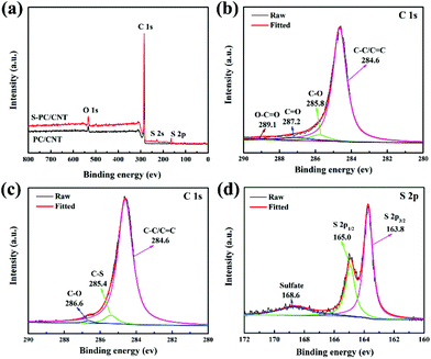 | ||
| Fig. 5 XPS survey spectrum of PC/CNT and S-PC/CNT composites (a); C 1s XPS spectra of PC/CNT (b); C 1s (c) and S 2p (d) XPS spectra of the S-PC/CNT composite. | ||
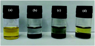 | ||
| Fig. 6 Digital image of the Li2S6 (0.005 mol L−1) in DOL/DME solution: (a) control; adsorption by (b) PC/CNT, (c) PC and (d) CNT. | ||
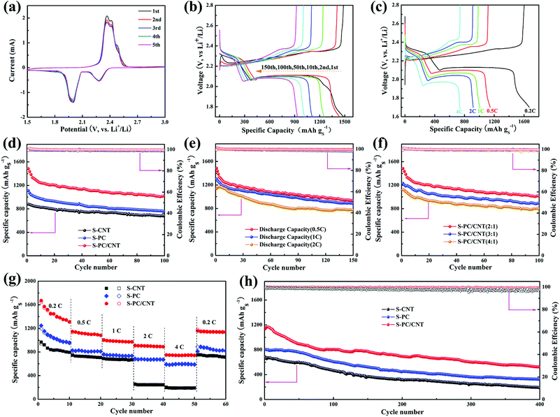
To evaluate the electrochemical performance of the S-PC/CNT composite as the cathode material for LSB, CR2025 coin cells with lithium foil as the anode were assembled for a test. The CV curves of the S-PC/CNT cathode obtained at a sweep rate of 0.1 mV s−1 for the first five cycles are represented in Fig. 7(a). In the cathodic scan, two well-defined peaks were observed at approximately 2.28 and 1.99 V. The reduction peak at 2.28 V is related to the reduction of elemental sulfur to long chain LiPS and another reduction peak at 1.99 V is associated with the further reduction of long chain LiPS to short chain LiPS (such as Li2S2, Li2S).43,44 Interestingly, there are two oxidation peaks at around 2.36 V and 2.41 V in the subsequent anodic scan, corresponding to the conversion of Li2S2/Li2S to long chain LiPS and sequential oxidation to element sulfur. These two oxidation peaks are similar to the previous reports,9,36,43,44 indicative of the high conductivity and low electrochemical polarization of the S-PC/CNT cathode. Moreover, both oxidation and reduction peaks are almost overlapped in the successive cycles, further verifying low electrochemical polarization and high reversibility ensuring superior cycling stability and excellent rate capability for the S-PC/CNT cathode.40,44 In sharp contrast, the S-CNT cathode exhibits only one oxidation peak, while the S-PC cathode exhibits two similar oxidation peaks (Fig. S6†). Notably, the S-PC/CNT and S-PC composites with abundant hierarchical pores of PCNs exhibit faster electrochemical reaction kinetics, as evidenced by the lower potential gap between oxidation and reduction peaks.18,45Fig. 7(b) shows the galvanostatic charge/discharge curves of the S-PC/CNT cathode at 0.5 C (1 C = 1675 mA g−1). All the discharge curves exhibit two typical plateaus, which are well consistent with the CV results. The charge/discharge voltage plateaus remain stable during the prolonged cycles, indicating an excellent potential stability. The galvanostatic charge/discharge curves of the S-PC/CNT cathode at various rates are depicted in Fig. 7(c). Although the charge/discharge voltage plateaus gradually rise/drop with the increased rates, the two obvious discharge plateaus are still observed even at a high rate of 4 C, suggesting an excellent rate capability owing to its 3D interconnected hierarchical porous structures and conductive networks.9,16
In Fig. 7(d), the cycling performances of S-PC/CNT, S-CNT, and S-PC cathodes at 0.5 C are compared. The S-PC/CNT cathode achieves an initial capacity as high as 1485.4 mA h g−1 with high active-sulfur utilization (88.7%). After 100 cycles, a high reversible capacity of 1016.5 mA h g−1 is still retained, corresponding to the capacity retention of 68.4%. In comparison, S-CNT and S-PC cathodes deliver initial discharge capacities of 1110.3 and 879.3 mA h g−1 and maintain the discharge capacities of 758.4 and 683.5 mA h g−1 after 100 cycles, respectively. This superior cycling stability of the S-PC/CNT cathode can be attributed to the synergistic effect of PCNs and CNTs, particularly those with strong polysulfide trapping and structural integrity. Fig. 7(e) shows the cycling performance of the S-PC/CNT cathode at charge/discharge rates of 0.5, 1 and 2 C. After 150 cycles, the S-PC/CNT cathode still exhibits a reversible capacity of 932.8 mA h g−1. When the current rate was increased to 1 C, the initial discharge capacity (1300.3 mA h g−1) becomes lower than the value at 0.5 C, but the cycling stability significantly improves. A high reversible capacity of 882.8 mA h g−1 remains after 150 cycles at 1 C, which corresponds to a capacity retention of 67.9%. Even at a high rate of 2 C, the composite cathode delivers an initial discharge capacity of 1138.0 mA h g−1. After 150 cycles, the capacity remains at 773.7 mA h g−1 with the capacity retention of 68.0%. It should be pointed out that the cycling performances of the S-PC/CNT composite are unambiguously better than those of many previously reported hybrid carbon materials-sulfur composites,30,35,36,46–56 as summarized in Table 1. Moreover, the electrochemical performance of S-PC/CNT (3![[thin space (1/6-em)]](https://www.rsc.org/images/entities/char_2009.gif) :
:![[thin space (1/6-em)]](https://www.rsc.org/images/entities/char_2009.gif) 1 or 4
1 or 4![[thin space (1/6-em)]](https://www.rsc.org/images/entities/char_2009.gif) :
:![[thin space (1/6-em)]](https://www.rsc.org/images/entities/char_2009.gif) 1) composites as cathodes were also evaluated for investigating the effect of sulfur loading. The S-PC/CNT composite with 66.3 wt% sulfur loading exhibits the higher specific capacity and Coulombic efficiency as shown in Fig. 7(f). As summarized in Fig. S7 and Table S2,† the S-PC/CNT composite with a lower sulfur content shows the best performance for LSB.
1) composites as cathodes were also evaluated for investigating the effect of sulfur loading. The S-PC/CNT composite with 66.3 wt% sulfur loading exhibits the higher specific capacity and Coulombic efficiency as shown in Fig. 7(f). As summarized in Fig. S7 and Table S2,† the S-PC/CNT composite with a lower sulfur content shows the best performance for LSB.
| Sample | Sulfur content (wt%) | Areal sulfur loadings (mg cm−2) | Cycling performance (mA h gs−1) |
|---|---|---|---|
| a Weight ratio of the composite. b Weight ratio of the electrode (not including the weight of current collectors). | |||
| Carbon black/MWCNTs30 | 81.7a/57.2b | 1.2–1.5 | 0.17 C, 1199/969 (100 cycles) |
| Biomass-derived porous carbon/CNTs35 | 60.9/48.7 | 2 | 0.1 C, 1739/1015 (50 cycles) |
| 0.5 C, 1698 /876 (100 cycles) | |||
| 1 C, 1623/622 (200 cycles) | |||
| Hierarchical porous carbon/CNTs36 | 65/52 | 1 | 1 C, 714/465 (250 cycles) |
| Graphene sheets/MWCNTs49 | 70/49 | Not provided | 0.2 C, 1396/844 (100 cycles) |
| N-Doped Aligned CNTs/graphene50 | 52.6/45 | 1 | 1 C, 1152 /880 (80 cycles) |
| Graphene/CNT@porous carbon51 | 50/45 | Not provided | 1 C, 1050 /870 (150 cycles) |
| 77/69 | 1 C, 914/658 (150 cycles) | ||
| Mesoporous nitrogen-doped carbon spheres/CNTs52 | 70/56 | 5 | 0.1 C, 1438/1200 (200 cycles) |
| N-Doped hollow carbon spheres/graphene53 | 62/50 | 3.9 | 0.2 C, 1360/940 (100 cycles) |
| 0.5 C, 800/520 (200 cycles) | |||
| N-Doped porous carbon/graphene54 | 65/45 | Not provided | 1.2 C, 1461/962 (120 cycles) |
| Hollow carbon spheres/graphene sheets55 | 65/52 | 0.9–1.1 | 0.6 C, 850/575 (200 cycles) |
| Graphitic carbon nanocages56 | 77/62 | Not provided | 0.1 C, 1375/943 (100 cycles) |
| PC/CNT (this work) | 66.3/53 | 1.2–1.5 | 0.5 C, 1485.4/825.1 (200 cycles) |
| 1 C, 1300.3 /821 (200 cycles) | |||
| 2 C, 1138/522 (400 cycles) | |||
| 74.4/60 | 0.5 C, 1243/777.7 (200 cycles) | ||
| 1 C, 1076.8 /734.1 (200 cycles) | |||
| 2 C, 995.7/411.9 (400 cycles) | |||
| 78.6/63 | 0.5 C, 1123.9/689.7 (200 cycles) | ||
| 1 C, 1007/659.8 (200 cycles) | |||
| 2 C, 857.2/378.9 (400 cycles) | |||
For further comparison, the rate capabilities of S-PC/CNT, S-CNT, and S-PC cathodes were investigated at various current rates depicted in Fig. 7(g). As expected, the S-PC/CNT cathode shows much higher specific capacity at the same current rates. The 3D interconnected hierarchical porous structure enables a high discharge capacity of 1670.1 mA h g−1 at 0.2 C. When the current rates were elevated to 0.5, 1, 2, and 4 C, the S-PC/CNT cathode delivered reversible capacities of 1146.6, 1006.0, 911.9, and 749 mA h g−1, respectively. As the current rate was restored to 0.2 C, the S-PC/CNT cathode recovered most of its capacity (1138.4 mA h g−1) and better than that of the control cathodes. The excellent rate capability should be attributed to the rapid charge transfer and excellent electron conductivity, which stem from the 3D interconnected hierarchical porous structure and conductive networks.36 Besides, the S-PC/CNT cathode shows an enhanced long-term cycling stability at 2 C, as is evident in Fig. 7(h). A discharge capacity of 522 mA h g−1 remained after 400 cycles, with only 0.1% decay per cycle and a coulombic efficiency of over 99%. In contrast, S-CNT and S-PC cathodes deliver relatively inferior cycling stabilities of only 190.1 and 326.8 mA h g−1, respectively, after 400 cycles. These findings indicate the superior cycling stability of LSB, which can be ascribed to the strong trapping to confine LiPS and the structural integrity of the electrode.14 The excellent stability of the S-PC/CNT cathode was further evidenced by EIS before and after cycling (Fig. S8 and S9†). As represented by the semicircles in the high frequency region of Nyquist plots, the charge transfer resistance (Rct) of the S-PC/CNT cathode is much lower than those of the other two cathodes, indicating faster ion transfer and higher electrical conductivity due to the stable 3D interconnected hierarchical porous structures and conductive networks.9,40 SEM and TEM observations also investigated the stability of the S-PC/CNT cathode, and the 3D interconnected hierarchical porous structures of PC/CNT remained intact after 200 cycles at 2 C, indicating the good structure stability of PC/CNT (Fig. S10†).
The outstanding overall electrochemical performance of the S-PC/CNT composites can be attributed to their unique structures. 3D interconnected hierarchical porous structures and conductive networks can provide rapid electrical/ionic transport and favorable electrolyte infiltration, resulting in excellent rate capability. Furthermore, PCNs with hierarchical porous structures can accommodate high sulfur loading and further act as a polysulfide reservoir to suppress the dissolution and diffusion of LiPS, improving the cycling performance with better capacity retention; CNTs with a highly robust conductive pathway facilitate electron transport and maintain structural integrity, having great impact on the cycling performance and rate capability.
Conclusions
In summary, PC/CNT with a 3D interconnected structure, designed as a novel host for sulfur loading, have been successfully synthesized via a simple one-pot pyrolysis strategy. The sulfur cathode benefits from the synergistic effect of these two carbon components and delivers high, reversible specific capacity, superior cycling performance, and excellent rate capability, owing to the rationally designed 3D interconnected structure. Notably, the S-PC/CNT cathode displays a long cycling performance with only 0.1% capacity decay per cycle over 400 cycles at 2 C. We believe that this attempt not only provides an effortless and scalable strategy for the construction of advanced carbon structures, but also gives new insights into the cathode design for achieving high performance lithium–sulfur batteries.Conflicts of interest
The authors declare no conflict of interest.Acknowledgements
We are grateful for financial support from the National Natural Science Foundation of China (No. 51674221).Notes and references
- D. Larcher and J. M. Tarascon, Nat. Chem., 2015, 7, 19–29 CrossRef CAS PubMed.
- P. G. Bruce, S. A. Freunberger, L. J. Hardwick and J. M. Tarascon, Nat. Mater., 2012, 11, 19–29 CrossRef CAS PubMed.
- Q. Pang, X. Liang, C. Y. Kwok and L. F. Nazar, Nat. Energy, 2016, 1, 16132 CrossRef CAS.
- A. Manthiram, S. H. Chung and C. Zu, Adv. Mater., 2015, 27, 1980–2006 CrossRef CAS PubMed.
- Z. W. Seh, Y. Sun, Q. Zhang and Y. Cui, Chem. Soc. Rev., 2016, 45, 5605–5634 RSC.
- S. S. Zhang, J. Power Sources, 2013, 231, 153–162 CrossRef CAS.
- G. Zhou, H. Tian, Y. Jin, X. Tao, B. Liu, R. Zhang, Z. W. Seh, D. Zhuo, Y. Liu and J. Sun, Proc. Natl. Acad. Sci. U. S. A., 2017, 114, 840–845 CrossRef CAS PubMed.
- C. Zheng, S. Niu, W. Lv, G. Zhou, J. Li, S. Fan, Y. Deng, Z. Pan, B. Li, F. Kang and Q. H. Yang, Nano Energy, 2017, 33, 306–312 CrossRef CAS.
- Z. Zheng, H. Guo, F. Pei, X. Zhang, X. Chen, X. Fang, T. Wang and N. Zheng, Adv. Funct. Mater., 2016, 26, 8952–8959 CrossRef CAS.
- Z. A. Ghazi, X. He, A. M. Khattak, N. A. Khan, B. Liang, A. Iqbal, J. Wang, H. Sin, L. Li and Z. Tang, Adv. Mater., 2017, 29, 1606817 CrossRef PubMed.
- J. Liang, Z. H. Sun, F. Li and H. M. Cheng, Energy Storage Mater., 2016, 2, 76–106 CrossRef.
- X. Liu, J. Q. Huang, Q. Zhang and L. Mai, Adv. Mater., 2017, 29, 1601759 CrossRef PubMed.
- Z. Li, H. B. Wu and X. W. Lou, Energy Environ. Sci., 2016, 9, 3061–3070 CAS.
- S. Chen, B. Sun, X. Xie, A. K. Mondal, X. Huang and G. Wang, Nano Energy, 2015, 16, 268–280 CrossRef CAS.
- X. Ji, K. T. Lee and L. F. Nazar, Nat. Mater., 2009, 8, 500–506 CrossRef CAS PubMed.
- G. Li, J. Sun, W. Hou, S. Jiang, Y. Huang and J. Geng, Nat. Commun., 2016, 7, 10601 CrossRef CAS PubMed.
- X. Wang, G. Li, J. Li, Y. Zhang, A. Wook, A. Yu and Z. Chen, Energy Environ. Sci., 2016, 9, 2533–2538 CAS.
- W. Yang, W. Yang, A. Song, L. Gao, G. Sun and G. Shao, J. Power Sources, 2017, 348, 175–182 CrossRef CAS.
- G. Ma, Z. Wen, M. Wu, C. Shen, Q. Wang, J. Jin and X. Wu, Chem. Commun., 2014, 50, 14209–14212 RSC.
- S. Liu, G. R. Li and X. P. Gao, ACS Appl. Mater. Interfaces, 2016, 8, 7783–7789 CAS.
- M. Liu, D. Zhou, Y. B. He, Y. Fu, X. Qin, C. Miao, H. Du, B. Li, Q. H. Yang and Z. Lin, Nano Energy, 2016, 22, 278–289 CrossRef CAS.
- F. Han, J. Yue, X. Fan, T. Gao, C. Luo, Z. Ma, L. Suo and C. Wang, Nano Lett., 2016, 16, 4521–4527 CrossRef CAS PubMed.
- X. Tao, Y. Liu, W. Liu, G. Zhou, J. Zhao, D. Lin, C. Zu, O. Sheng, W. Zhang, H. W. Lee and Y. Cui, Nano Lett., 2017, 17, 2967–2972 CrossRef CAS PubMed.
- F. Liu, Q. Xiao, H. B. Wu, F. Sun, X. Liu, F. Li, Z. Le, L. Shen, G. Wang, M. Cai and Y. Lu, ACS Nano, 2017, 11, 2697–2705 CrossRef CAS PubMed.
- S. Bai, X. Liu, K. Zhu, S. Wu and H. Zhou, Nat. Energy, 2016, 1, 16094 CrossRef CAS.
- W. Yang, W. Yang, J. Feng, Z. Ma and G. Shao, Electrochim. Acta, 2016, 210, 71–78 CrossRef CAS.
- W. Kong, L. Yan, Y. Luo, D. Wang, K. Jiang, Q. Li, S. Fan and J. Wang, Adv. Funct. Mater., 2017, 27, 1606663 CrossRef.
- J. Zhang, C. P. Yang, Y. X. Yin, L. J. Wan and Y. G. Guo, Adv. Mater., 2016, 28, 9539–9544 CrossRef CAS PubMed.
- Z. Zhang, L. L. Kong, S. Liu, G. R. Li and X. P. Gao, Adv. Energy Mater., 2017, 7, 1602543 CrossRef.
- Z. Zhang, H. K. Jing, S. Liu, G. R. Li and X. P. Gao, J. Mater. Chem. A, 2015, 3, 6827–6834 CAS.
- Y. Zhao, W. Wu, J. Li, Z. Xu and L. Guan, Adv. Mater., 2014, 26, 5113–5118 CrossRef CAS PubMed.
- D. Su, M. Cortie and G. Wang, Adv. Energy Mater., 2017, 7, 1602014 CrossRef.
- X. Fang and H. Peng, Small, 2015, 11, 1488–1511 CrossRef CAS PubMed.
- H. J. Peng, J. Q. Huang, M. Q. Zhao, Q. Zhang, X. B. Cheng, X. Y. Liu, W. Z. Qian and F. Wei, Adv. Funct. Mater., 2014, 24, 2772–2781 CrossRef CAS.
- D. W. Xu, S. Xin, Y. You, Y. Li, H. P. Cong and S. H. Yu, ChemNanoMat, 2016, 2, 712–718 CrossRef CAS.
- C. Luo, S. Niu, G. Zhou, W. Lv, B. Li, F. Kang and Q. H. Yang, Chem. Commun., 2016, 52, 12143–12146 RSC.
- W. Yang, W. Yang, F. Ding, L. Sang, Z. Ma and G. Shao, Carbon, 2017, 111, 419–427 CrossRef CAS.
- Y. Shao, M. F. El-Kady, C. W. Lin, G. Zhu, K. L. Marsh, J. Y. Hwang, Q. Zhang, Y. Li, H. Wang and R. B. Kaner, Adv. Mater., 2016, 28, 6719–6726 CrossRef CAS PubMed.
- J.-Q. Huang, Z. Wang, Z.-L. Xu, W. G. Chong, X. Qin, X. Wang and J.-K. Kim, ACS Appl. Mater. Interfaces, 2016, 8, 28663–28670 CAS.
- T. Chen, B. Cheng, G. Zhu, R. Chen, Y. Hu, L. Ma, H. Lv, Y. Wang, J. Liang, Z. Tie, Z. Jin and J. Liu, Nano Lett., 2017, 17, 437–444 CrossRef CAS PubMed.
- Z. Wang, Y. Dong, H. Li, Z. Zhao, H. B. Wu, C. Hao, S. Liu, J. Qiu and X. W. D. Lou, Nat. Commun., 2014, 5, 5002 CrossRef CAS PubMed.
- G. Zhou, J. Sun, Y. Jin, W. Chen, C. Zu, R. Zhang, Y. Qiu, J. Zhao, D. Zhuo, Y. Liu, X. Tao, W. Liu, K. Yan, H. R. Lee and Y. Cui, Adv. Mater., 2017, 29, 1603366 CrossRef PubMed.
- Z. Xiao, Z. Yang, L. Wang, H. Nie, M. e. Zhong, Q. Lai, X. Xu, L. Zhang and S. Huang, Adv. Mater., 2015, 27, 2891–2898 CrossRef CAS PubMed.
- Z. Li, L. Yuan, Z. Yi, Y. Liu, Y. Xin, Z. Zhang and Y. Huang, Nanoscale, 2014, 6, 1653–1660 RSC.
- Z. Zhang, Y. Lai, Z. Zhang, Z. Kai and L. Jie, Electrochim. Acta, 2014, 129, 55–61 CrossRef CAS.
- Q. Wang, Z.-B. Wang, C. Li and D.-M. Gu, J. Mater. Chem. A, 2017, 5, 6052–6059 CAS.
- Q. Wang, Z.-B. Wang, M. Yang, C. Li and D.-M. Gu, J. Mater. Chem. A, 2017, 5, 16796–16802 CAS.
- C. Li, X.-L. Sui, Z.-B. Wang, Q. Wang and D.-M. Gu, Chem. Eng. J., 2017, 326, 265–272 CrossRef CAS.
- R. Chen, T. Zhao, J. Lu, F. Wu, L. Li, J. Chen, G. Tan, Y. Ye and K. Amine, Nano Lett., 2013, 13, 4642–4649 CrossRef CAS PubMed.
- C. Tang, Q. Zhang, M. Q. Zhao, J. Q. Huang, X. B. Cheng, G. L. Tian, H. J. Peng and F. Wei, Adv. Mater., 2014, 26, 6100–6105 CrossRef CAS PubMed.
- H. J. Peng, J. Q. Huang, M. Q. Zhao, Q. Zhang, X. B. Cheng, X. Y. Liu, W. Z. Qian and F. Wei, Adv. Funct. Mater., 2014, 24, 2772–2781 CrossRef CAS.
- J. Song, M. L. Gordin, T. Xu, S. Chen, Z. Yu, H. Sohn, J. Lu, Y. Ren, Y. Duan and D. Wang, Angew. Chem., Int. Ed., 2015, 54, 4325–4329 CrossRef CAS PubMed.
- G. Zhou, Y. Zhao and A. Manthiram, Adv. Energy Mater., 2015, 5, 1402263 CrossRef.
- J. Shan, Y. Liu, Y. Su, P. Liu, X. Zhuang, D. Wu, F. Zhang and X. Feng, J. Mater. Chem. A, 2016, 4, 314–320 CAS.
- F. Wu, J. Li, Y. Su, J. Wang, W. Yang, N. Li, L. Chen, S. Chen, R. Chen and L. Bao, Nano Lett., 2016, 16, 5488–5494 CrossRef CAS PubMed.
- J. Zhang, C. P. Yang, Y. X. Yin, L. J. Wan and Y. G. Guo, Adv. Mater., 2016, 28, 9539–9544 CrossRef CAS PubMed.
Footnote |
| † Electronic supplementary information (ESI) available. See DOI: 10.1039/c7nr06805k |
| This journal is © The Royal Society of Chemistry 2018 |

