Embedding liquid lasers within or around aqueous microfluidic droplets†
Lu
Zheng
a,
Min
Zhi
b,
Yinthai
Chan
b and
Saif A.
Khan
 *a
*a
aDepartment of Chemical and Biomolecular Engineering, 3 Engineering Drive 3, National University of Singapore, Singapore 117582, Singapore. E-mail: saifkhan@nus.edu.sg
bDepartment of Chemistry, 3 Science Drive 3, National University of Singapore, Singapore 117543, Singapore
First published on 23rd November 2017
Abstract
In this paper, we demonstrate the incorporation of dye-based liquid lasers within or around flowing aqueous microfluidic droplets. In particular, we use dye solutions in benzyl alcohol, and either disperse an ensemble of small (∼20 μm) lasing droplets within large (∼500 μm) aqueous droplets flowing in a simple glass capillary-based microfluidic device, or ‘wrap’ a thin (∼10 μm) lasing benzyl alcohol shell around larger (∼560 μm) microfluidic aqueous droplets. We experimentally and theoretically characterize the lasing behavior in both cases, which is supported by whispering-gallery mode (WGM) optical resonances at the droplet interfaces. We showcase a simple application of our method, which highlights the advantages of having embedded, spatially segregated laser sources within a droplet containing a model analyte solution. With this method, each microfluidic droplet now functions not only as an isolated experiment flask, but is also capable of on drop sensing that exploits WGM-based lasing, thus expanding the possibilities for online monitoring of biophysical/biochemical processes and sensitive detection of biomolecules in droplet-based microfluidics.
Introduction
The coupling of light with matter flowing through a microfluidic channel (optofluidics) has dramatically expanded the microfluidics toolbox over the past decade, particularly in lab-on-a-chip methods for very diverse biological and molecular sensing applications.1–3 In this context, the emergence of optofluidic laser-based sensing platforms offers a paradigm shift for microfluidic biological/chemical analysis4 in which fluorescence-based methods are predominantly used to detect analytes.2 These fluorescence-based methods suffer from well-acknowledged drawbacks, such as weak signals or strong background noise when the samples are diluted or when small volumes are probed. In contrast, optofluidic lasers allow the amplification of sensing signals without amplification of the background noise.4 Optofluidic lasers typically consist of two main components – a microfluidic laser cavity for optical feedback, and a fluorophore solution as the gain medium, which enables intra-cavity detection.4 Within the cavity, resonant light is bounced back and forth thousands to millions of times and, as a consequence, the target molecule is sampled orders of magnitude more times as compared to conventional sensing. Several different types of optofluidic laser platforms have been demonstrated, primarily differing in the type of cavity used. In the past few years, optofluidic lasers employing distributed feedback gratings, Fabry–Pérot cavities and ring resonators in conjunction with microfluidic channels have been developed and applied to a number of bio-sensing applications.4–11In this context, there has been considerable interest in the use of droplets as high-quality optical microcavities due to their small, controllable sizes and smooth, spherical interfaces.12 Spherical liquid droplets having a higher refractive index than their surroundings can support whispering gallery mode (WGM) optical resonances, in which incident light is trapped in rings around the droplet interface; the wavelengths of the supported modes and the inter-mode spacing can be precisely tuned by varying the diameter of the droplet, and are well described by Mie theory.13 When an appropriate gain medium is present inside the liquid droplets, these WGMs can support optical feedback, and therefore lasing.14–17 Inspired by the pioneering demonstration of gel-based lasers in the 1970s,18 droplet-based lasers have been demonstrated using free-falling or levitated droplets in air17,19,20 and with spherical droplets sitting on superhydrophobic surfaces.19,21,22 These methods are versatile, and can handle a variety of different liquids due to the high refractive index contrast between almost any liquid and air; however, methods involving direct exposure of droplets to air typically suffer from rapid liquid evaporation, and cannot be integrated easily with other lab-on-a-chip functionalities. Optofluidic lasing via the self-assembly of monolayer gain material at the liquid–liquid interface in a sessile droplet has been recently demonstrated, with tremendous potential for probing molecular level biophysical and biochemical processes.23
More recently, exciting demonstrations of lasing with dye-containing microfluidic droplets flowing in an immiscible fluid within a microchannel have been reported.12,24,25 While these demonstrations hold considerable promise, especially as on-chip light sources for spectroscopy and flow cytometry, there remain several challenges before microfluidic dye droplet lasers can be used for molecular and biological sensing applications. Since the droplets are immersed in a carrier liquid (such as a fluorinated oil) instead of air, the relatively lower refractive index contrast between the droplet and the carrier liquid compromises the ability of the cavity to trap light effectively.25 In particular, for aqueous droplets, which are most relevant for biological applications,26–28 the index contrast is far too low, rendering the cavities too ‘leaky’ optically for lasing to be achieved.25 Furthermore, the presence of fluorescent dye molecules in the same liquid phase as the analyte(s) can potentially interfere with the biochemical/biophysical event under observation, thus necessitating low dye concentrations, which once again compromises the lasing performance. In addition, organic laser dyes can be quite sensitive to environmental conditions (such as pH, polarity, and ionic strength), which further restricts the application of dye droplet lasers in biologically relevant sensing applications.
In this paper, we demonstrate how dye-based liquid lasers can be incorporated within or around aqueous microfluidic droplets, paving the way for their utilization in a broader array of applications than is currently possible. In particular, we use dye solutions in benzyl alcohol, and either disperse an ensemble of small (∼20 μm) droplets within large (∼500 μm) aqueous droplets flowing, or ‘wrap’ a thin (∼10 μm) lasing benzyl alcohol shell around larger (∼500 μm) microfluidic aqueous droplets in simple glass capillary-based microfluidic devices. We experimentally and theoretically characterize the WGM lasing behavior in both cases, and showcase a simple application of our method, which highlights the advantages of having embedded, spatially segregated laser sources within a droplet containing a model analyte solution. With our method, each aqueous microfluidic droplet can now function not only as an isolated experiment flask, but is also capable, for the first time, of on drop sensing that exploits WGM-based lasing, thus expanding the possibilities for the online monitoring of biophysical/biochemical processes and sensitive detection of biomolecules.
Results and discussion
I. Embedding liquid lasers within aqueous microfluidic droplets
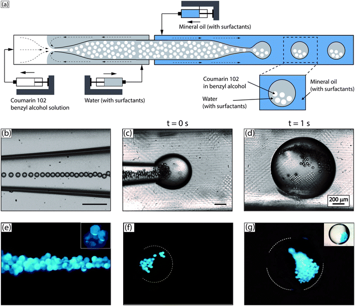
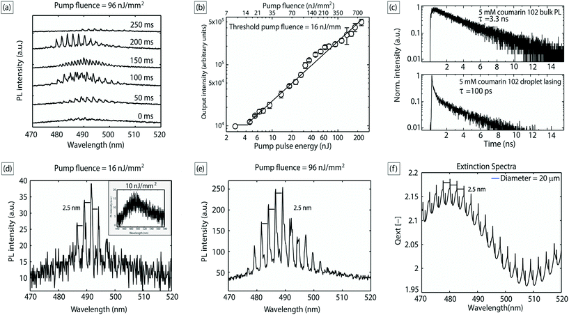
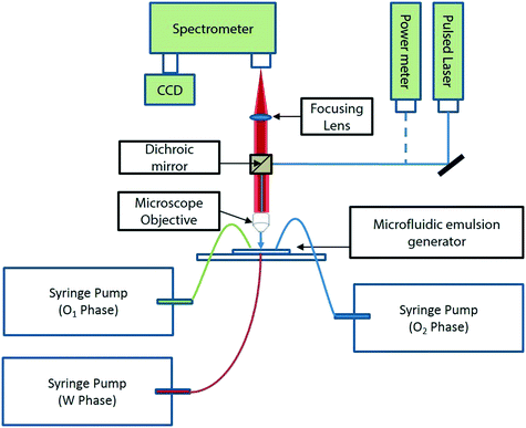
As shown in Fig. 1, O1/W/O2 double emulsion droplets (outer aqueous droplet diameter ∼500 μm; inner benzyl alcohol droplet diameter ∼20 μm) were generated using two microfluidic glass capillary devices in series, as described in the Experimental section (with further details in the ESI†). Droplet sizes were obtained from digital analysis of stereomicroscope images. The number of inner droplets can be tuned by varying the relative flow rates of the three phases, from ∼20 to ∼100. The inner droplets contained a solution of a laser dye – coumarin 102 – in benzyl alcohol (5 mM). The outer aqueous droplets contained a small quantity (0.5 wt%) of polyvinyl alcohol as surfactant (refractive index, nD = 1.33), and the carrier fluid was light mineral oil.25 Benzyl alcohol was chosen as a solvent for the laser dye due to its high refractive index (nD = 1.54), providing a high refractive index contrast with water, ensuring efficient WGM-based light confinement at the boundary of the dye loaded inner droplets.19,24 The droplets were excited by a Ti:sapphire pump laser system with a repetition rate of 1 kHz and a pulse duration of 100 fs at an excitation wavelength of 400 nm. The excitation spot size was ∼600 μm in diameter and droplet speed ∼3 mm s−1. Fig. 1(e)–(g) are stereomicroscopic images of the excited droplets, obtained by blocking out the scattered laser light through a dichroic mirror; the presence of WGMs can be seen as intensely lit circumferential regions around the droplet periphery (inset, Fig. 1(e)).The coupling efficiency of the excitation light with the flowing droplets depends on the location of the droplet within the illumination spot. Efficient optical excitation was achieved in our system (Fig. 2(a)) by virtue of the continuous flow of the droplets and the low frequency of droplet generation (∼1 Hz), which ensured that each droplet had a residence time of ∼0.25 s in the pump illumination spot and was excited by ∼250 pulses from the excitation source. As each droplet flowed past the illumination spot, the ensemble of emission spectra collected from it showed a unique, high coupling maximum of output intensity, as shown in Fig. 2(a), which is consistent across different droplets. This consistency is worthy of note, and possibly due to the larger droplet acting as a lens to focus the randomly emitted light from the benzyl alcohol inner droplets into the objective lens, as previously reported by Brody and Quake in the context of biophysical measurements.30
Fig. 2(b) shows the output intensities averaged from 8 consecutive droplets as a function of pump pulse energy; the plot clearly exhibits a threshold behavior characteristic of lasing, with a threshold pump fluence of about 16 nJ mm−2. Emission lifetime data obtained from time-correlated single photon counting (TCSPC) measurements further validates the occurrence of lasing (Fig. 2(c)). The lifetime data of the lasing droplets were fitted with an exponential decay function  , with a time constant τ of ∼100 ps (R2 = 0.98), which was much shorter than the lifetime of photoluminescence from the bulk solution (τ ∼3.3 ns, R2 = 0.98), indicating the occurrence of stimulated emission, which is a process much faster than spontaneous emission.31 As mentioned above, the positions of the WGMs (and inter-mode spacing) are sensitive to the diameter of the optical cavity,19,24,32 and it is crucial to have tight control over the size of the inner liquid laser droplets for effective and robust applications. In the above demonstration, the inner droplets had a mean diameter of 20 μm with a standard deviation of ∼3%. The monodispersity of the droplet resonators is further validated by the invariant and equal mode spacing of the emission spectra collected (∼2.5 nm), as exemplified by the emission spectra in Fig. 2(d) and (e). The observed modes and inter-mode spacing can be predicted from droplet extinction spectra calculated by the classical Mie theory,13 which we used to model the WGM spectral structure for our system. The spectra were calculated (with an in-house MATLAB code) for spherical benzyl alcohol droplets of 20 μm diameter surrounded by water. As shown in Fig. 2(f), the predicted mode spacing was found to be 2.5 nm, in agreement with our experimental results. We explored droplet sizes in the 10–40 μm range, which at its lower end comprises small cavities with optical gain distributed over a limited number of modes but with low Q-factor,12,17 and at its upper end entails large cavities with high Q-factor but whose optical gain is spread over numerous modes. Cavity sizes beyond this range either suffered from an inability to support WGMs or too much undesirable absorption and fluorescence from the bulk of the dye-containing droplets that does not participate in WGM lasing (which is intrinsically a surface phenomenon).
Finally, it is worth noting that the apparent aggregation of the inner droplets (Fig. 1(g)) is a hydrodynamic phenomenon, well observed in previous studies on microparticles and beads suspended within flowing microfluidic droplets.29 When the aqueous droplets flow, the internal velocity field tends to aggregate the suspended benzyl alcohol droplets, especially for larger numbers of suspended droplets. This aggregation is entirely reversible, and the inner droplets return to a non-aggregated state upon cessation of the flow. The aggregation phenomenon is not essential to our method, and we believe that it does not affect our results in any significant way under the stated experimental conditions. Thus, measured mode spacings for the WGMs are found to be in good agreement with Mie theory predictions, which assume independent and optically non-interacting droplets. Furthermore, when the number of droplets is small (∼20), we do not observe dynamic aggregation, and the estimated Q-factor of our WGMs with and without aggregation is roughly the same (∼1000). That being said, it is theoretically possible for closely spaced cavities to couple optically under certain conditions.33,34 The conditions for optical coupling of liquid cavities, such as the ones used in our work, is an interesting fundamental issue, which we are currently exploring in our laboratories with close-packed flowing lattices of droplets.
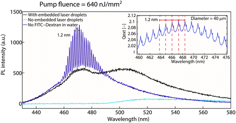
Next, we demonstrate a proof-of-concept demonstration in which the non-invasive droplet cavity lasers embedded within aqueous droplets can be completely shut off due to the presence of an absorbing molecule in their vicinity. This achievement exemplifies new capabilities our method makes possible compared to previous studies, thereby laying the foundation for novel applications that will be the subject of future work. We used a 20 μM solution of a fluorescein isothiocyanate–dextran conjugate (hereafter referred to as FITC-Dextran) as the aqueous phase in the droplets. FITC-Dextran has an excitation maximum at 490 nm, which is located well within the emission range of the embedded droplet laser ensemble. We then excited these FITC-Dextran loaded droplets (embedded with smaller laser droplets) with the same pulsed laser at a pump fluence of 640 nJ mm−2. The sizes of the inner benzyl alcohol droplets were tuned to be 38 μm (with a standard deviation <5%) by varying the ratio between O1 and W flow rates. As shown in Fig. 3, we recorded very low emission from the FITC-Dextran in the absence of the embedded lasers, as its absorption cross section at the excitation wavelength of 400 nm is very low. However, with the embedded lasers, FITC-Dextran emission was greatly enhanced by a factor of ∼8 (based on peak emission intensity), while the WGM spectral modes of the embedded lasers were completely shut off due to energy transfer from coumarin 102 to FITC-dextran. Subsequently, the laser emission was replaced by a broad and weak photoluminescence, in stark contrast to the case with no FITC-dextran. As also shown in Fig. 3, the mode spacing decreased from 2.5 nm to 1.2 nm, consistent with Mie theory simulation predictions for these droplets obtained from our in-house MATLAB code (Fig. 3 inset). To accomplish the above demonstration in the fluorescence regime, where the donor emission is dramatically suppressed, would require the invasive presence of the reporter molecule within the aqueous droplets. Emission from the reporter molecule would therefore be far more susceptible to interference with other components of the aqueous medium.
From the standpoint of applications, the modulation in the laser output (i.e. intensity and/or spectral characteristics) due to the presence (or absence) of certain molecules in the vicinity of the liquid lasers, as shown above, can be used as a highly sensitive detection method for biochemical/biophysical events. It offers a potentially lower detection limit as compared to fluorescence-based techniques, and also enables the detection of hard-to-distinguish small signals.4 The embedded lasers can also act as efficient light sources for (potentially spatially resolved) online spectroscopy or photochemistry applications.
II. Wrapping liquid lasers around aqueous microfluidic droplets
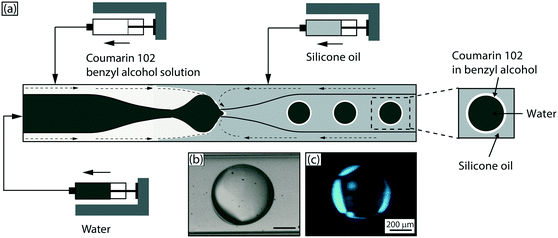
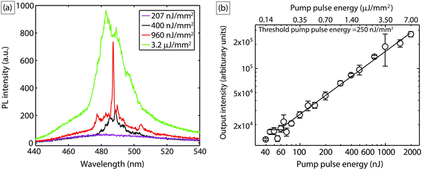
Next, we demonstrate another mode of employing liquid lasers where, instead of loading the lasing droplets within an aqueous droplet, we wrap a thin liquid laser shell around the aqueous droplet. This is an all-liquid version of another often used optofluidic laser sensing configuration – the liquid-core optical ring-resonator (LCORR).35–37 As indicated in Fig. 4(a), a coaxial flow of a coumarin 102 solution (5 mM) in benzyl alcohol with ultrapure water through a single capillary device was introduced into another flow-focusing capillary device, where core–shell droplets were formed in a silicone oil carrier phase via a hydrodynamic focusing mechanism (see Experimental section for details). The aqueous droplets have an outer diameter ∼560 μm and a shell thickness of ∼10 μm. The core–shell droplets were excited by the same Ti:sapphire laser system (Coherent) with a repetition rate of 1 kHz and a pulse duration of 100 fs at wavelength of 400 nm. In this case, light is now confined as WGMs propagating at the interface between benzyl alcohol (nD = 1.54) and silicone oil (nD = 1.40). Each droplet spent an average of ∼0.2 s in the pump spot and was excited ∼200 times. Fig. 4(c) illustrates light localization and amplification at the circumference of the droplets, highlighting the lasing droplet ‘skin’ in this case, in contrast to the embedded laser ‘spots’ above.Fig. 5(a) shows typical PL spectra at pump fluence below the lasing threshold and WGM-modulated emission spectra when pump fluence exceeds the lasing threshold. There is a clear spectral narrowing between 480–500 nm when droplets were pumped above the threshold. However, due to the large size of the droplets used here and the lower refractive index contrast between the cavity (benzyl alcohol nD = 1.54) and the surrounding medium (silicone oil nD = 1.40) as compared to the previous case, the spectra do not clearly evince multi-mode laser behavior; this is a straightforward consequence of the fact that WGM mode spacing is inversely proportional to droplet (cavity) diameter.32 Recall that the mode spacing was 2.5 nm for droplets of diameter ∼20 μm; in contrast, the mode spacing in the shell around the large aqueous droplets (diameter ∼ 560 μm) now becomes comparable to the resolution of the spectrometer (0.13 nm). This was validated again by calculating WGM spectra for a 560 μm diameter droplet, with the new refractive index contrast of the system used here, where indeed a possible mode spacing of ∼0.1 nm was predicted. Fig. 5(b) shows the output intensities averaged from 10 droplets as a function of pump pulse energy, which clearly exhibits the threshold behavior of lasing, with a threshold pump fluence of 250 nJ mm−2.
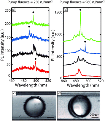
As mentioned earlier, most of the spectra obtained in our experiment do not clearly evince multi-mode lasing behavior due to the narrow mode spacing, and instead, showed a spectrally wide modal gain profile (as shown in the 3.2 μJ mm−2 pump fluence case). However, the apparent single mode lasing profile at 960 nJ mm−2 pump fluence in Fig. 5(a) is worthy of note. This apparent mode selection process was observed in a fraction (∼10%) of the excited droplets at all pump fluences above threshold, as seen in Fig. 6(a) and (b), which are collections of PL spectra obtained at different powers. While a detailed investigation of this phenomenon is beyond the scope of this proof-of-concept demonstration, we provide a tentative explanatory hypothesis here. The apparent mode selection may be attributed to a unique hydrodynamic feature of the flowing core-shell droplet configuration – as the droplets flow, viscous forces move the inner droplet towards the front stagnation point of the outer droplet,38 which breaks symmetry, and causes one side of the shell to be much thinner than the other (as indicated in the representative stereomicroscope images of Fig. 6(c) and (d)). The thickness of the shell directly determines whether higher order (radial) WGM modes (l ≥ 2), which penetrate spatially inwards into the droplet, can be excited. Higher order modes excite more of gain material, and can thus give larger lasing signals despite having lower Q-factors;39 the attenuation of these modes upon asymmetric thinning of the liquid shells in our experiments directly explains the apparent mode selection process observed in our experiments. This phenomenon was also studied by Lee et al.,37 who reported that in the case of a thin glass ‘micro-bubble’ in air, with a wall thickness of ∼0.5 μm, more than 96% of the higher order WGM modes would effectively ‘leak into’ the micro-bubble bulk, which in their case contained an aqueous solution of analyte. In their case, only the first order (l = 1) radial WGM modes were confined (∼90%) to the thin glass wall of the microbubble. In our experiments, since there was no gain medium inside the central water droplet, the higher order modes are effectively extinguished, and apparent mode selection is observed. Furthermore, the somewhat probabilistic nature of this phenomenon in our experiments can be attributed due to the inherent stochasticity of the optical coupling in this system of flowing droplets, and can be addressed by active synchronization of the droplet position with the pump pulses.24
One can envision a version of the proof-of-concept demonstration in section I above applied to this configuration. In such an application, the analyte would be a molecule in the aqueous core that acts as an acceptor in an energy transfer process, with the lasing gain medium in the shell acting as a donor. Thus, the presence of analyte in the aqueous droplet would either modify or shut down lasing in the shell. A further and exciting advantage of the shell configuration is the potential to achieve single mode lasing through a mode selection process by tuning shell thickness, as pointed out above. Single mode emission would be desirable from several viewpoints; it would have a more stable output by eliminating mode competition, and would be much more amenable to interrogation of subtle wavelength shifts due to the presence of analytes in the aqueous core.40–43
In summary, we have presented the first demonstration of embedded dye-based liquid lasers within or around aqueous microfluidic droplets, and have experimentally and theoretically characterized the lasing behavior in both cases. Such lasers greatly advance the functionality and information content of each flowing microfluidic droplet, which now functions not only as an isolated experiment flask, but is also capable of on drop sensing that exploits WGM-based lasing, thus expanding the possibilities for online monitoring of biophysical/biochemical processes, sensitive detection of biomolecules and online spectroscopy. From the standpoint of applications in sensing, this platform enables fundamentally different capabilities that are not possible when analytes and fluorescent reporters are present within the same droplet. There is a substantial body of existing literature on WGM-based sensing, with clearly established advantages over fluorescence-based methods. WGM resonators have been exploited for sensing environmental factors such as pressure, temperature, and humidity, and for chemical and biomolecular sensing.44–46 However, this body of literature has hitherto relied on solid, glass-based cavities external to the fluidics. Our work brings fluidic WGM cavities in direct and intimate contact with aqueous analytes, and therefore includes all these previous demonstrations within its scope. Finally, our work also points to interesting and very fundamental issues at the interface of optics and microfluidics, such as the mode selection behavior observed in the shell configuration, or optical coupling in systems of flowing, closely packed droplets, which are the topics of ongoing investigation in our laboratories.
Experimental section
Materials
N,N-Dimethyl-n-octadecyl-3-aminopropyltrimethoxysilyl chloride (DMOAP), poly(vinyl) alcohol (PVA) (M.W. – 67![[thin space (1/6-em)]](https://www.rsc.org/images/entities/char_2009.gif) 000), coumarin 102 (99% dye content), span 80, benzyl alcohol (99.5%), mineral oil (light), and silicone oil (10 cst) were purchased from Sigma-Aldrich (Singapore) and used as received. Pico-Glide™ 1 was purchased from The Dolomite Centre Ltd. Ultrapure water (18.3 MΩ) obtained using a Millipore Milli-Q purification system was used to prepare aqueous PVA solution. Harvard PHD 22/2000 series syringe pumps were used to dispense fluids into the emulsion generator. Square and cylindrical glass capillaries of ID 1 mm and 0.7 mm respectively were purchased from Arte glass associates Co. Ltd., Japan.
000), coumarin 102 (99% dye content), span 80, benzyl alcohol (99.5%), mineral oil (light), and silicone oil (10 cst) were purchased from Sigma-Aldrich (Singapore) and used as received. Pico-Glide™ 1 was purchased from The Dolomite Centre Ltd. Ultrapure water (18.3 MΩ) obtained using a Millipore Milli-Q purification system was used to prepare aqueous PVA solution. Harvard PHD 22/2000 series syringe pumps were used to dispense fluids into the emulsion generator. Square and cylindrical glass capillaries of ID 1 mm and 0.7 mm respectively were purchased from Arte glass associates Co. Ltd., Japan.
Methods
Conflicts of interest
There are no conflicts of interest to declare.Acknowledgements
The authors gratefully acknowledge funding from A*STAR PSF grant no. 1421200076.References
- C. Monat, P. Domachuk and B. Eggleton, Nat. Photonics, 2007, 1, 106–114 CrossRef CAS.
- J. Godin, C. H. Chen, S. H. Cho, W. Qiao, F. Tsai and Y. H. Lo, J. Biophotonics, 2008, 1, 355–376 CrossRef CAS PubMed.
- X. Fan and I. M. White, Nat. Photonics, 2011, 5, 591–597 CrossRef CAS PubMed.
- X. Fan and S.-H. Yun, Nat. Methods, 2014, 11, 141–147 CrossRef CAS PubMed.
- X. Zhang, W. Lee and X. Fan, Lab Chip, 2012, 12, 3673–3675 RSC.
- Y. Sun and X. Fan, Angew. Chem., Int. Ed., 2012, 51, 1236–1239 CrossRef CAS PubMed.
- Q. Chen, X. Zhang, Y. Sun, M. Ritt, S. Sivaramakrishnan and X. Fan, Lab Chip, 2013, 13, 2679–2681 RSC.
- W. Lee and X. Fan, Anal. Chem., 2012, 84, 9558–9563 CrossRef CAS PubMed.
- G. Aubry, Q. Kou, J. Soto-Velasco, C. Wang, S. Meance, J. He and A. Haghiri-Gosnet, Appl. Phys. Lett., 2011, 98, 111111 CrossRef.
- Z. Li, Z. Zhang, T. Emery, A. Scherer and D. Psaltis, Opt. Express, 2006, 14, 696–701 CrossRef CAS PubMed.
- M. C. Gather and S. H. Yun, Nat. Photonics, 2011, 5, 406–410 CrossRef CAS.
- S. K. Tang, R. Derda, Q. Quan, M. Lončar and G. M. Whitesides, Opt. Express, 2011, 19, 2204–2215 CrossRef CAS PubMed.
- C. F. Bohren and D. R. Huffman, Absorption and scattering of light by small particles, John Wiley & Sons, 2008 Search PubMed.
- A. B. Matsko and V. S. Ilchenko, IEEE J. Sel. Top. Quantum Electron., 2006, 12, 3 CrossRef CAS.
- P. Chýlek, H.-B. Lin, J. D. Eversole and A. J. Campillo, Opt. Lett., 1991, 16, 1723–1725 CrossRef.
- H.-B. Lin, A. Huston, B. Justus and A. J. Campillo, Opt. Lett., 1986, 11, 614–616 CrossRef CAS PubMed.
- H.-B. Lin, J. D. Eversole and A. J. Campillo, J. Opt. Soc. Am. B, 1992, 9, 43–50 CrossRef CAS.
- T. Hansch, Opt. Photonics News, 2005, 16, 14–16 CrossRef.
- R. K. Chang and A. J. Campillo, Optical processes in microcavities, World scientific, 1996 Search PubMed.
- G. Chen, M. M. Mazumder, R. K. Chang, J. C. Swindal and W. P. Acker, Prog. Energy Combust. Sci., 1996, 22, 163–188 CrossRef CAS.
- M. Hossein-Zadeh and K. J. Vahala, Opt. Express, 2006, 14, 10800–10810 CrossRef PubMed.
- A. Kiraz, A. Sennaroglu, S. Doğanay, M. Dündar, A. Kurt, H. Kalaycıoğlu and A. Demirel, Opt. Commun., 2007, 276, 145–148 CrossRef CAS.
- H. Zhang, A. Balram, D. D. Meng and Y. Sun, ACS Photonics, 2017, 4, 621–625 CrossRef CAS.
- S. K. Tang, Z. Li, A. R. Abate, J. J. Agresti, D. A. Weitz, D. Psaltis and G. M. Whitesides, Lab Chip, 2009, 9, 2767–2771 RSC.
- M. Tanyeri, R. Perron and I. M. Kennedy, Opt. Lett., 2007, 32, 2529–2531 CrossRef CAS PubMed.
- D. T. Chiu and R. M. Lorenz, Acc. Chem. Res., 2009, 42, 649–658 CrossRef CAS PubMed.
- Y. Sun, S. I. Shopova, C.-S. Wu, S. Arnold and X. Fan, Proc. Natl. Acad. Sci. U. S. A., 2010, 107, 16039–16042 CrossRef CAS PubMed.
- S.-Y. Teh, R. Lin, L.-H. Hung and A. P. Lee, Lab Chip, 2008, 8, 198–220 RSC.
- G. K. Kurup and A. S. Basu, Biomicrofluidics, 2012, 6, 022008 CAS.
- J. P. Brody and S. R. Quake, Appl. Phys. Lett., 1999, 74, 144–146 CrossRef CAS.
- S. I. Shopova, J. M. Cupps, P. Zhang, E. P. Henderson, S. Lacey and X. Fan, Opt. Express, 2007, 15, 12735–12742 CrossRef CAS PubMed.
- S.-X. Qian, J. B. Snow, H.-M. Tzeng and R. K. Chang, Science, 1986, 231, 486–489 CAS.
- L. Ge and H. E. Türeci, Phys. Rev. A: At., Mol., Opt. Phys., 2015, 92, 013840 CrossRef.
- M. L. Povinelli, S. G. Johnson, M. Lončar, M. Ibanescu, E. J. Smythe, F. Capasso and J. Joannopoulos, Opt. Express, 2005, 13, 8286–8295 CrossRef PubMed.
- H. Li, Y. Guo, Y. Sun, K. Reddy and X. Fan, Opt. Express, 2010, 18, 25081–25088 CrossRef CAS PubMed.
- I. M. White, H. Oveys and X. Fan, Opt. Lett., 2006, 31, 1319–1321 CrossRef PubMed.
- W. Lee, Y. Sun, H. Li, K. Reddy, M. Sumetsky and X. Fan, Appl. Phys. Lett., 2011, 99, 091102 CrossRef.
- S. Sadhal and H. Oguz, J. Fluid Mech., 1985, 160, 511–529 CrossRef.
- J. Schafer, J. P. Mondia, R. Sharma, Z. Lu, A. Susha, A. Rogach and L. Wang, Nano Lett., 2008, 8, 1709–1712 CrossRef CAS PubMed.
- J. Dong and K.-I. Ueda, Appl. Phys. Lett., 2005, 87, 151102 CrossRef.
- C.-Y. Gong, Y. Gong, W.-L. Zhang, Y. Wu, Y.-J. Rao, G.-D. Peng and X. Fan, IEEE J. Sel. Top. Quantum Electron., 2018, 24, 1–6 CrossRef.
- L. Narducci, J. Tredicce, L. Lugiato, N. Abraham and D. Bandy, Phys. Rev. A: At., Mol., Opt. Phys., 1986, 33, 1842 CrossRef CAS.
- X. Wu, Y. Sun, J. D. Suter and X. Fan, Appl. Phys. Lett., 2009, 94, 241109 CrossRef.
- N. M. Hanumegowda, I. M. White, H. Oveys and X. Fan, Sens. Lett., 2005, 3, 315–319 CrossRef CAS.
- F. Vollmer, S. Arnold, D. Braun, I. Teraoka and A. Libchaber, Biophys. J., 2003, 85, 1974–1979 CrossRef CAS PubMed.
- F. Vollmer, D. Braun, A. Libchaber, M. Khoshsima, I. Teraoka and S. Arnold, Appl. Phys. Lett., 2002, 80, 4057–4059 CrossRef CAS.
- R. A. L. Leon, W. Y. Wan, A. Z. M. Badruddoza, T. A. Hatton and S. A. Khan, Cryst. Growth Des., 2014, 14, 140–146 CAS.
- A. I. Toldy, A. Z. M. Badruddoza, L. Zheng, T. A. Hatton, R. Gunawan, R. Rajagopalan and S. A. Khan, Cryst. Growth Des., 2012, 12, 3977–3982 CAS.
- A. Utada, E. Lorenceau, D. Link, P. Kaplan, H. Stone and D. Weitz, Science, 2005, 308, 537–541 CrossRef CAS PubMed.
- S.-H. Kim, J. W. Kim, J.-C. Cho and D. A. Weitz, Lab Chip, 2011, 11, 3162–3166 RSC.
Footnote |
| † Electronic supplementary information (ESI) available. See DOI: 10.1039/c7lc00701a |
| This journal is © The Royal Society of Chemistry 2018 |

