Hierarchical NiCo2O4 nanosheets on carbon nanofiber films for high energy density and long-life Li–O2 batteries†
Guoxue
Liu
,
Lei
Zhang
*,
Suqing
Wang
,
Liang-Xin
Ding
and
Haihui
Wang
 *
*
School of Chemistry and Chemical Engineering, South China University of Technology, Guangzhou 510640, China. E-mail: celeizhang@scut.edu.cn; hhwang@scut.edu.cn
First published on 22nd June 2017
Abstract
Designing oxygen cathodes with both high energy density and excellent cycling stability is a great challenge in the development of lithium–oxygen (Li–O2) batteries for energy storage systems. Herein, we design a novel structure of hierarchical NiCo2O4 nanosheets on porous carbon nanofiber films (denoted as NiCo2O4@CNFs) as an oxygen cathode for lithium–oxygen batteries. The NiCo2O4@CNFs cathode delivers a high specific discharge capacity of 4179 mA h g−1, a high energy density of 2110 W h kg−1 and superior cycling stability over 350 cycles. The excellent electrochemical performance of the NiCo2O4@CNFs cathode can be attributed to the rational design and engineering of catalysts and porous conductive electrodes. These results indicate that the NiCo2O4@CNFs electrode is a promising candidate for high energy density and long-life Li–O2 batteries. Additionally, the rational design of the hierarchical catalyst constructed low-dimensional nanostructure and the lightweight porous carbon nanofiber electrode can be also used for other metal–oxygen batteries, such as zinc–oxygen (Zn–O2) batteries, aluminum–oxygen (Al–O2) batteries, and sodium–oxygen (Na–O2) batteries.
Rechargeable lithium–oxygen (Li–O2) batteries are unmatched candidates amongst future electrochemical energy storage devices for electric vehicles due to their high theoretical energy density of 3505 W h kg−1, which is about 10 times higher than that of conventional Li-ion batteries (360 W h kg−1).1–6 In a typical prototype, a Li–O2 battery is composed of an Li+ conducting electrolyte, a separator, a lithium anode, and a porous O2 breathing cathode, and its cycling mechanism is based on the oxygen reduction reaction (ORR) and the oxygen evolution reaction (OER) between Li+ and oxygen on the cathode: 2Li+ + O2 + 2e− ↔ Li2O2.7,8 As a result, the key of the development of high-performance Li–O2 batteries depends on the cathode, which needs to meet such requirements: highly active bifunctional ORR/OER catalysts, and porous conductive electrodes for oxygen diffusion and electron transport, as well as offering enough space to meet the needs of Li2O2 deposition.9–12
Despite their superior theoretical storage capacity, constructing cycling stable Li–O2 battery cathodes is still facing materials challenges.11,13 This is traced to the sluggish kinetics of the ORR/OER giving large discharge/charge overpotentials and the random deposition of Li2O2 blocking the permeation path for oxygen and the electrolyte, leading to low round-trip efficiency, poor rate capability, and short cycling performance.9,14 From the catalyst point of view, although the most efficient catalysts for the sluggish bifunctional ORR/OER are still noble metals,15–19 low cost earth-abundant transition metal oxides, such as MnO2,20–23 NiCo2O4,24,25 Co3O4,26–28 MnCo2O4,29,30 and CoMn2O4,31,32 are preferred for practical application. Among these, NiCo2O4-based materials have received considerable attention due to their rich redox reaction sites from both redox couples of Co3+/Co2+ and Ni3+/Ni2+, good electrical conductivity, and affordable cost.33–35 Hence, low-dimensional nanostructured NiCo2O4-based catalysts, such as 0D nanoparticles, 1D nanorods/nanowires/nanotubes and 2D nanosheets, have been reported as bifunctional ORR/OER catalysts for rechargeable Li–O2 batteries.36–41 Low dimensional NiCo2O4 nanostructures possess highly exposed active sites and short diffusion length for the ORR/OER, which can lead to a high discharge capacity and low overpotentials.36 However, these low-dimensional nanostructures cannot ensure enough space for solid Li2O2 deposition, which could cover catalytically active sites and result in poor cycling performance.24 Also, the mass transport channels of Li+ and oxygen are easily clogged due to relatively small pores of low-dimensional nanostructures, leading to cell failure.42 Therefore, the fabrication of NiCo2O4-based catalysts with efficiently sufficient space and an accessible porous structure is highly desirable for Li–O2 batteries.
As to the porous conductive electrode, a “binder-free” cathode has recently been introduced as an ideal electrode to avoid the side reaction between the binder and electrolyte.43 Among the substrates, Ni foam and carbon textile are most commonly used because of their good breathability, high conductivity and good stability. For example, Liu et al. synthesized a cathode of δ-MnO2 assembled by ultrathin nanosheets on Ni foam coated with graphene, which showed excellent stability to enhance the cycling stability of Li–O2 batteries.23 Zhang et al. described that TiO2 nanowires grown on carbon clothes exhibited good electrochemical performance attributed to their high mechanical and chemical stability.44 However, the high mass densities of Ni foam and carbon textile will lead to sacrificing capacity and energy density.39 Thus, it is highly demanded to design and develop a lightweight cathode with high catalytic ORR/OER activities for realizing the high energy density of Li–O2 batteries.
To achieve a Li–O2 battery with high cycling stability and high energy density, it is highly necessary to combine a rationally structured catalyst and a lightweight porous conductive electrode. Herein, we propose a novel structure of hierarchical NiCo2O4 nanosheets on porous carbon nanofiber films (denoted as NiCo2O4@CNFs), for high energy density and long-life Li–O2 batteries. The nanostructured cathode integrates several desirable design rationales for high-performance Li–O2 batteries based on low-dimensional ultrathin nanosheets, lightweight conductive carbon networks, and a binder-free cathode. With the help of this rational design, the NiCo2O4@CNFs cathode exhibits excellent electrochemical performance including a high specific discharge capacity of 4179 mA h g−1, an excellent energy density of 2110 W h kg−1, and especially superior cycling stability over 350 cycles.
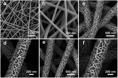
The fabrication procedure of porous NiCo2O4 nanosheets on carbon nanofiber films and the structure of the Li–O2 battery are described in Fig. 1. Typically, porous carbon nanofiber films were prepared via a facile electrospinning technique followed by carbonization. In step I, Ni–Co precursor nanosheets were grown on carbon nanofiber films by a hydrothermal method to form core–shell structures. In step II, the Ni–Co precursor nanosheets were transformed into porous NiCo2O4 nanosheets through annealing and the NiCo2O4@CNFs cathode was finally obtained. The morphology and microstructure of the cathode were investigated by field emission scanning electron microscopy (FESEM). As shown in Fig. 2, the randomly arranged carbon nanofibers form conductive networks with numerous irregular micrometer-scale pores between the carbon nanofibers, which could enhance electron transfer among cathodes and offer sufficient channels for cathode breathing. From the high magnification SEM, it can be seen that the as-prepared carbon nanofibers have an average diameter of about 180 nm with a smooth surface (Fig. 2b). The X-ray diffraction (XRD) pattern of CNFs shows no obvious diffraction peaks, indicating that the carbon nanofibers consist of typical amorphous carbon (Fig. S1, ESI†). Afterwards, Ni–Co precursors were grown on carbon nanofibers through a simple hydrothermal method. As shown in Fig. 2c and d, the low-magnification FESEM image of NiCo2O4@CNFs (Fig. 2c) displays that the Ni–Co precursor nanosheets uniformly coat the carbon nanofibers and the pores between the individual carbon nanofibers are not been covered. The magnified FESEM image (Fig. 2d) shows that the Ni–Co precursor nanosheets are around 10 nm thick. After annealing at 350 °C in a nitrogen atmosphere, the Ni–Co precursor nanosheets were converted to NiCo2O4 nanosheets. From the FESEM images (Fig. 2e), it can be clearly observed that the NiCo2O4 shell is still constructed by nanosheet-like subunits on the carbon nanofibers because of the robust support of the carbon nanofibers. Interestingly, from the FESEM image of a single 1D NiCo2O4@CNFs (Fig. 2f), the NiCo2O4 nanosheets are clearly observed with a rough and porous surface.
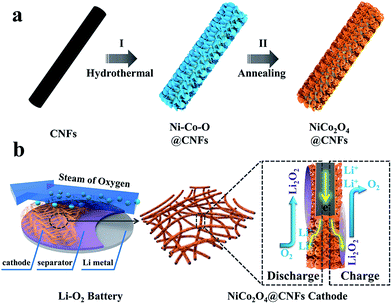 | ||
| Fig. 1 (a) Schematic illustration of the fabrication of the NiCo2O4@CNFs cathode; (b) structure of the rechargeable Li–O2 battery containing this cathode. | ||
The crystallographic phase of the NiCo2O4 nanosheets was characterized by X-ray powder diffraction (XRD), as shown in Fig. S2 (ESI†). All of the diffraction peaks in the XRD pattern can be unambiguously assigned to the spinel NiCo2O4 (JCPDS no. 20-0781).24,34 No other diffraction peaks from possible impurities are observed, suggesting that the Ni–Co precursor is converted into highly pure spinel NiCo2O4. By thermogravimetric analysis (TGA, Fig. S3, ESI†), the mass content of NiCo2O4 in NiCo2O4@CNFs is approximately 40%.36,39 The chemical compositions of NiCo2O4@CNFs were further analyzed by energy dispersive X-ray (EDX) spectroscopy (Fig. S4, ESI†). The total mass of Ni, Co, and O is 43.8%, which is slightly higher than the TGA result, which might be caused by the oxygen atoms of CNFs. In virtue of 1D nanofibers and the ultrathin sheet-like subunits, these NiCo2O4@CNFs have a relatively large Brunauer–Emmett–Teller (BET) surface area of about 178 m2 g−1 (N2 adsorption desorption isotherm is given in Fig. S5, ESI†).
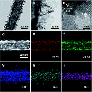
To further understand the porous nanosheet structure, transmission electron microscopy (TEM) was performed (Fig. 3). In Fig. 3a and b, it can be clearly observed that NiCo2O4 nanosheets are uniformly grown on the CNFs (Fig. 3a), and the surface of NiCo2O4 contains abundant mesopores (Fig. 3b). Furthermore, the high-resolution TEM (HRTEM, Fig. 3c) images of NiCo2O4 nanosheets exhibits lattice fringes with inter-planar spacings of 0.287 nm and 0.470 nm, corresponding to the (200) and (111) planes of NiCo2O4. Energy-dispersive X-ray (EDX) mapping was used to further analyze the distribution of the catalyst on CNFs, as shown in Fig. 3d–i. The Ni, Co, and O elements are uniformly distributed around a carbon nanofiber, and the C element is distributed into the core of the composite. In addition, energy dispersive X-ray (EDX, Fig. S6, ESI†) spectral line-scan results show that the C element is mainly detected inside the NiCo2O4@CNFs, and the Ni, Co, and O elements are mainly detected on the shell, which could suggest that the CNFs are covered by a uniform coating layer of NiCo2O4.45
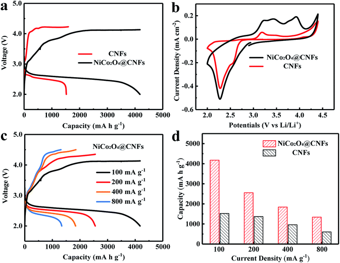
We subsequently investigated the electrochemical properties of the NiCo2O4@CNFs as a cathode for Li–O2 batteries. Fig. 4a shows the discharge–charge voltage profiles of NiCo2O4@CNFs and CNFs cathodes at a current density of 100 mA g−1. The NiCo2O4@CNFs cathode shows a high initial discharge capacity of 4179 mA h g−1, which is higher than that of the CNFs cathode (1591 mA h g−1). Furthermore, the NiCo2O4@CNFs cathode presents lower overpotentials than CNFs, which suggests that the NiCo2O4 catalyst has higher electrocatalytic activities toward the ORR/OER.46,47 The NiCo2O4@CNFs cathode with different loading masses at the same mass current density was investigated as shown in Fig. S7.† The specific capacities of the NiCo2O4@CNFs cathode with loading masses of 0.134, 0.268, and 0.536 mg cm−2 were 4179, 2231, and 1992 mA h g−1, respectively. The morphological changes of the NiCo2O4@CNFs cathode after the 1st full discharge and 1st charge are examined (Fig. S8, ESI†). As shown Fig. S8b, ESI,† the NiCo2O4 shell is constructed by nanosheet-like subunits on the carbon nanofibers. The part of 3D spaces with NiCo2O4 nanosheets was filled with the discharge product (Li2O2) during the discharge process from 0 mA h g−1 to 1000 mA h g−1 (Fig. S8c, ESI†). Then, the 3D structure was completely covered by the discharge product after being discharged to 2.0 V (Fig. S8d, ESI†). After the charge process, the 3D structure consisting of porous NiCo2O4 nanosheets was still observed obviously (Fig. S8e, ESI†) suggesting that the NiCo2O4@CNFs can remain stable enough during the discharge and charge processes and the discharge product inside the 3D structure was decomposed completely after charging, which suggest that the NiCo2O4@CNFs cathode show good mass transfer channels during the discharge and charge processes enhancing its capacity and recovery.47 In order to further investigate the electrocatalytic activities of the NiCo2O4@CNFs, cyclic voltammetry (CV) was performed at a scan rate of 0.1 mV s−1 in the voltage window of 2.0–4.5 V, as shown in Fig. 4b. The CV behaviors are similar to those previously reported, suggesting that the oxygen electrodes have the same reaction pathway.23,46,48 Specifically, one reduction peak can be clearly observed, which can be ascribed to the oxygen reduction. In addition, the NiCo2O4@CNFs cathode exhibits a lower onset ORR potential and larger ORR peak current density than CNFs. Consistent with the result of the discharge–charge profile, the CV curve of the NiCo2O4@CNFs cathode shows three oxidation peaks at around 3.24, 3.44, and 3.93 V, respectively, which is attributed to the stepwise process of decomposition of Li2O2.14,48,49 Moreover, the NiCo2O4@CNFs cathode shows a higher OER peak current density than CNFs. The rate capability of the NiCo2O4@CNFs and CNFs cathodes was investigated through galvanostatic discharge–charge at various current densities from 100 to 800 mA g−1, as shown in Fig. 4c and d. The NiCo2O4@CNFs cathode delivers a high discharge capacity of 1339 mA h g−1 with a corresponding coulombic efficiency (CE) of 97.8% at a high current density of 800 mA g−1 (Fig. 4c), while the discharge capacity of the CNFs is 603 mA h g−1 with a CE of 74.5% at 800 mA g−1 (Fig. S9, ESI†).
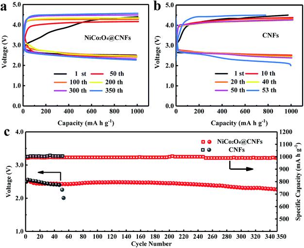
The cycling tests of Li–O2 batteries were performed to evaluate the long-term catalytic activity of the NiCo2O4@CNFs cathode. The cycling performance was tested at a current density of 200 mA g−1 with a fixed specific capacity of 1000 mA h g−1 (Fig. 5). As shown in Fig. 5a and b, the NiCo2O4@CNFs cathode shows lower ORR/OER overpotentials and a higher energy efficiency than the CNFs cathode. As shown in Fig. 5c, the terminal discharge voltage of the NiCo2O4@CNFs cathode is still above 2.0 V even after 350 cycles. In contrast, the terminal discharge voltage of the CNFs cathode declines to under 2.0 V after only 53 cycles. In addition, to further investigate the stability of the NiCo2O4@CNFs cathode, the morphologies of the cathode were characterized by SEM after discharge and charge cycles, as shown in Fig. S10.† The NiCo2O4 nanosheets on CNFs still have a good structure after the cycles. The full discharge–charge curves of the Li–O2 battery with the NiCo2O4@CNFs cathode are shown in Fig. S11 (ESI†). The NiCo2O4@CNFs cathode exhibits low overpotentials, especially a charge potential of under 4.0 V in Fig. S11a (ESI†). In addition, the NiCo2O4@CNFs cathode achieves the highest capacity of 7168 mA h g−1 in the 18th cycle and still maintains a high capacity of 5738 mA h g−1 after 20 full cycles (Fig. S11b, ESI†). The excellent cycling stability indicates that the NiCo2O4@CNFs cathode maintains a good bi-functional catalytic activity for a long time.8,46,47
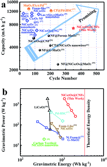
Compared with reported NiCo2O4 based cathodes (Table S1, ESI†), it is worth mentioning that the Li–O2 battery performance of the NiCo2O4@CNFs cathode is significantly outstanding, including its cycling stability and capacity. Meanwhile, the relationship between the discharge capacity and cycle performance of reported cathodes is shown in Fig. 6a. The Li–O2 battery performance of the NiCo2O4@CNFs cathode is much better than those of the reported binder-free cathode. It should be noticed that the NiCo2O4@CNFs cathode shows better cycling performance despite lower initial discharge capacity than the binder-added cathodes. Furthermore, the NiCo2O4@CNFs cathode exhibits an extremely high energy density of 2110 W h kg−1, which is much higher than that of reported Li–O2 batteries (Fig. 6b).17,23,24,39,50
The excellent cycling performance and high energy density of the NiCo2O4@CNFs cathode might be attributed to the rational design and engineering of catalysts and porous conductive electrodes.47 Specifically, compared with the binder-free NiCo2O4-based cathode (<6 wt%) in Table S1,† the hierarchical nanostructures with a high NiCo2O4 loading mass (40 wt%) could provide more active sites for the ORR/OER and spaces for Li2O2 formation and deposition during cycling processes. In addition, the low-dimensional NiCo2O4 nanosheets facilitate Li+/O2 transfer on the shell structure. Meanwhile, the NiCo2O4 shell on CNFs could prevent the side reaction between carbon and intermediates at high potential.8,19,45 Furthermore, the “binder-free” NiCo2O4@CNFs cathode with highly conducive CNFs also avoids binder-induced problems, such as the side reaction of organic binder decomposition.23,44,48 Thus, combining the hierarchical NiCo2O4 nanostructure and porous conductive electrode, the NiCo2O4@CNFs cathode exhibits high capacity and excellent cycling performance. Simultaneously, with the low mass density of the porous conductive electrode (CNFs) in NiCo2O4@CNFs, an extremely high energy density of 2110 W h kg−1 can be achieved.
Conclusions
In summary, hierarchical NiCo2O4 nanosheets grown on carbon nanofiber films were synthesized via a hydrothermal method followed by annealing treatment as binder free cathodes for Li–O2 batteries. The NiCo2O4@CNFs cathode simultaneously integrates an efficient bifunctional catalyst with a rationally designed electrode for long life, high energy density Li–O2 batteries based on low-dimensional ultrathin nanosheets, lightweight conductive carbon networks, and a binder-free cathode. When evaluated as a cathode for Li–O2 batteries, the NiCo2O4@CNFs electrode can manifest high specific capacity, high energy density and excellent cycling stability. From these results, the rational design of the hierarchical catalyst constructed low-dimensional nanostructure and the lightweight porous carbon nanofiber electrode toward oxygen cathodes can be also used for other metal–oxygen batteries, such as Zn–O2 batteries, Al–O2 batteries, and Na–O2 batteries.Acknowledgements
This work was financially supported by the National Key Research and Development Program of China (2016YFA0202600), the “Thousand Talents Program”, National Natural Science Foundation of China (21606088, 51621001, 21576100), and the Pearl River S&T Nova Program of Guangzhou (201610010062).Notes and references
- P. G. Bruce, S. A. Freunberger, L. J. Hardwick and J. M. Tarascon, Nat. Mater., 2012, 11, 19 CrossRef CAS PubMed.
- N. Feng, P. He and H. Zhou, Adv. Energy Mater., 2016, 6, 201502303 Search PubMed.
- Y. Y. Shao, F. Ding, J. Xiao, J. Zhang, W. Xu, S. Park, J. G. Zhang, Y. Wang and J. Liu, Adv. Funct. Mater., 2013, 23, 987 CrossRef CAS.
- Y. Li, X. Wang, S. Dong, X. Chen and G. Cui, Adv. Energy Mater., 2016, 6, 201600751 Search PubMed.
- G. Girishkumar, B. McCloskey, A. C. Luntz, S. Swanson and W. Wilcke, J. Phys. Chem. Lett., 2010, 1, 2193 CrossRef CAS.
- J. Lu, L. Li, J. B. Park, Y. K. Sun, F. Wu and K. Amine, Chem. Rev., 2014, 114, 5611 CrossRef CAS PubMed.
- W. B. Luo, X. W. Gao, D. Q. Shi, S. L. Chou, J. Z. Wang and H. K. Liu, Small, 2016, 12, 3031 CrossRef CAS PubMed.
- K. Liao, X. Wang, Y. Sun, D. Tang, M. Han, P. He, X. Jiang, T. Zhang and H. Zhou, Energy Environ. Sci., 2015, 8, 1992 CAS.
- L. Grande, E. Paillard, J. Hassoun, J. B. Park, Y. J. Lee, Y. K. Sun, S. Passerini and B. Scrosati, Adv. Mater., 2015, 27, 784 CrossRef CAS PubMed.
- J. Wang, Y. Li and X. Sun, Nano Energy, 2013, 2, 443 CrossRef CAS.
- Z. W. Chang, J. J. Xu, Q. C. Liu, L. Li and X. B. Zhang, Adv. Energy Mater., 2015, 5, 201500633 Search PubMed.
- A. Kraytsberg and Y. Ein-Eli, J. Power Sources, 2011, 196, 886 CrossRef CAS.
- J. S. Lee, S. T. Kim, R. Cao, N. S. Choi, M. Liu, K. T. Lee and J. Cho, Adv. Energy Mater., 2011, 1, 34 CrossRef CAS.
- Y. C. Lu, B. M. Gallant, D. G. Kwabi, J. R. Harding, R. R. Mitchell, M. S. Whittingham and S. H. Yang, Energy Environ. Sci., 2013, 6, 750 CAS.
- Z. Peng, S. A. Freunberger, Y. Chen and P. G. Bruce, Science, 2012, 337, 563 CrossRef CAS PubMed.
- D. Oh, J. F. Qi, Y. C. Lu, Y. Zhang, S. H. Yang and A. M. Belcher, Nat. Commun., 2013, 4, 2756 Search PubMed.
- J. J. Xu, Z. L. Wang, D. Xu, L. L. Zhang and X. B. Zhang, Nat. Commun., 2013, 4, 2438 Search PubMed.
- Y. C. Lu, Z. C. Xu, H. A. Gasteiger, S. Chen, H. S. Kimberly and S. H. Yang, J. Am. Chem. Soc., 2010, 132, 12170 CrossRef CAS PubMed.
- F. J. Li, D. M. Tang, Z. L. Jian, D. Q. Liu, D. Golberg, A. Yamada and H. S. Zhou, Adv. Mater., 2014, 26, 4659 CrossRef CAS PubMed.
- A. Débart, A. J. Paterson, J. Bao and P. G. Bruce, Angew. Chem., Int. Ed., 2008, 120, 4597 CrossRef.
- Y. Cao, Z. Wei, J. He, J. Zang, Q. Zhang, M. Zheng and Q. Dong, Energy Environ. Sci., 2012, 5, 9765 CAS.
- X. Hu, F. Cheng, X. Han, T. Zhang and J. Chen, Small, 2015, 11, 809 CrossRef CAS PubMed.
- S. Liu, Y. Zhu, J. Xie, Y. Huo, H. Y. Yang, T. Zhu, G. Cao, X. Zhao and S. Zhang, Adv. Energy Mater., 2014, 4, 201301960 Search PubMed.
- L. L. Liu, J. Wang, Y. Y. Hou, J. Chen, H. K. Liu, J. Z. Wang and Y. P. Wu, Small, 2016, 12, 602 CrossRef CAS PubMed.
- B. Sun, X. Huang, S. Chen, Y. Zhao, J. Zhang, P. Munroe and G. Wang, J. Mater. Chem. A, 2014, 2, 12053 CAS.
- Y. Liang, Y. Li, H. Wang, J. Zhou, J. Wang, T. Regier and H. Dai, Nat. Mater., 2011, 10, 780 CrossRef CAS PubMed.
- W. H. Ryu, T. H. Yoon, S. H. Song, S. Jeon, Y. J. Park and I. D. Kim, Nano Lett., 2013, 13, 4190 CrossRef CAS PubMed.
- T. Y. Ma, S. Dai, M. Jaroniec and S. Z. Qiao, J. Am. Chem. Soc., 2014, 136, 13925 CrossRef CAS PubMed.
- D. Oh, J. F. Qi, B. H. Han, G. R. Zhang, T. J. Carney, J. Ohmura, Y. Zhang, S. H. Yang and A. M. Belcher, Nano Lett., 2014, 14, 4837 CrossRef CAS PubMed.
- H. Wang, Y. Yang, Y. Liang, G. Zheng, Y. Li, Y. Cui and H. Dai, Energy Environ. Sci., 2012, 5, 7931 CAS.
- S. Peng, L. Li, Y. Hu, M. Srinivasan, F. Cheng, J. Chen and S. Ramakrishna, ACS Nano, 2015, 9, 1945 CrossRef CAS PubMed.
- C. Li, X. P. Han, F. Y. Cheng, Y. X. Hu, C. C. Chen and J. Chen, Nat. Commun., 2015, 6, 7345 CrossRef CAS PubMed.
- S. X. Liu, L. F. Hu, X. J. Xu, A. A. Al-Ghamdi and X. S. Fang, Small, 2015, 11, 4267 CrossRef CAS PubMed.
- Z. Gao, W. Yang, J. Wang, N. Song and X. Li, Nano Energy, 2015, 13, 306 CrossRef CAS.
- G. Zhang and X. W. Lou, Adv. Mater., 2013, 25, 976 CrossRef CAS PubMed.
- H. Gong, H. R. Xue, T. Wang, H. Guo, X. L. Fan, L. Song, W. Xia and J. P. He, ACS Appl. Mater. Interfaces, 2016, 8, 18060 CAS.
- H. Xue, X. Mu, J. Tang, X. Fan, H. Gong, T. Wang, J. He and Y. Yamauchi, J. Mater. Chem. A, 2016, 4, 9106 CAS.
- Y. Luo, F. L. Lu, C. Jin, Y. R. Wang, R. Z. Yang and C. H. Yang, J. Power Sources, 2016, 319, 19 CrossRef CAS.
- H. R. Xue, S. C. Wu, J. Tang, H. Gong, P. He, J. P. He and H. S. Zhou, ACS Appl. Mater. Interfaces, 2016, 8, 8427 CAS.
- L. Y. Li, L. F. Shen, P. Nie, G. Pang, J. Wang, H. S. Li, S. Y. Dong and X. G. Zhang, J. Mater. Chem. A, 2015, 3, 24309 CAS.
- A. Riaz, K. N. Jung, W. Chang, K. H. Shin and J. W. Lee, ACS Appl. Mater. Interfaces, 2014, 6, 17815 CAS.
- J. Xie, X. Yao, Q. Cheng, I. P. Madden, P. Dornath, C. C. Chang, W. Fan and D. Wang, Angew. Chem., Int. Ed., 2015, 54, 4299 CrossRef CAS PubMed.
- D. Xiao, S. Dong, J. Guan, L. Gu, S. Li, N. Zhao, C. Shang, Z. Yang, H. Zheng, C. Chen, R. Xiao, Y. S. Hu, H. Li, G. Cui and L. Chen, Adv. Energy Mater., 2015, 5, 1400664 CrossRef.
- Q. C. Liu, J. J. Xu, D. Xu and X. B. Zhang, Nat. Commun., 2015, 6, 7892 CrossRef CAS PubMed.
- Z. L. Jian, P. Liu, F. J. Li, P. He, X. W. Guo, M. W. Chen and H. S. Zhou, Angew. Chem., Int. Ed., 2014, 53, 442 CrossRef CAS PubMed.
- G. Liu, H. Chen, L. Xia, S. Wang, L. X. Ding, D. Li, K. Xiao, S. Dai and H. Wang, ACS Appl. Mater. Interfaces, 2015, 7, 22478 CAS.
- J. J. Xu, D. Xu, Z. L. Wang, H. G. Wang, L. L. Zhang and X. B. Zhang, Angew. Chem., Int. Ed., 2013, 52, 3887 CrossRef CAS PubMed.
- F. F. Tu, J. Xie, S. C. Zhang, G. S. Cao, T. J. Zhu and X. B. Zhao, J. Mater. Chem. A, 2015, 3, 5714 CAS.
- D. Zhai, H. H. Wang, J. Yang, K. C. Lau, K. Li, K. Amine and L. A. Curtiss, J. Am. Chem. Soc., 2013, 135, 15364 CrossRef CAS PubMed.
- R. R. Mitchell, B. M. Gallant, C. V. Thompson and S. H. Yang, Energy Environ. Sci., 2011, 4, 2952 CAS.
Footnote |
| † Electronic supplementary information (ESI) available. See DOI: 10.1039/c7ta03703a |
| This journal is © The Royal Society of Chemistry 2017 |

