 Open Access Article
Creative Commons Attribution 3.0 Unported Licence
Molecular design of advanced lubricant base fluids: hydrocarbon-mimicking ionic liquids†
Erik Nyberg *,
Catur Y. Respatiningsih and
Ichiro Minami
Division of Machine Elements, Department of Engineering Sciences and Mathematics, Luleå University of Technology, Luleå SE-97187, Sweden. E-mail: erik.nyberg@ltu.se; Tel: +46 920 49 1237
First published on 19th January 2017
Abstract
This paper describes the molecular design and tribological evaluation of novel room-temperature ionic liquid (RTIL) lubricants, abbreviated as P–SiSOs. The RTILs are designed to mimic hydrocarbons, in order to ensure their compatibility with existing tribosystems as well as enable use of conventional additives. Steel-on-steel ball-on-flat reciprocating tribotests performed under atmospheric conditions show that the neat P–SiSOs exhibit favorable performances, resulting in friction and wear significantly lower than those in the case of the perfluoropolyether lubricants used as references. Tribotests performed at elevated loads and temperatures indicate the formation of friction-reducing boundary films of the neat P–SiSOs. The tribological performance of the P–SiSO is improved further by the incorporation of additives conventionally used in hydrocarbon oils. When used in a concentration of 5 wt%, the additives glycerol monooleate, dibenzyl disulfide, and oleylamine improve the tribological characteristics of P–SiSO. These results indicate that molecular-designed hydrocarbon-mimicking RTIL lubricants can exhibit suitable performances in the neat form and that their performances can be improved further by using conventional additives, as in the case of hydrocarbon base oil-additive systems.
1. Introduction
Gears, bearings, and other moving mechanical assemblies require lubrication in order to operate reliably and efficiently. Over the past century, the dominating approach to machinery lubrication has been based on hydrocarbons. During the same time period, extensive research efforts have developed friction- and wear-reducing additives that improve the tribological performance of lubricants.1,2 Conventional hydrocarbon base fluids however, are not able to meet the challenging requirements for operations in extreme environments; therefore, synthetic alternatives are used. However, synthetic fluids often have chemical structures that are very different from conventional hydrocarbons. This frequently leads to tribosystem compatibility issues. Also, the synthetic fluids struggle to take advantage of existing additive technology. Room temperature ionic liquids (RTILs) are a class of synthetic fluids that have garnered much attention recently. As explained below, their ionic nature leads to many options for molecular design, giving them high potential as advanced lubricant base fluids.RTILs are composed entirely of cations and anions, forming salts with melting points lower than room temperature. Since RTILs are prepared by combining cationic and anionic moieties, millions of combinations with varying properties are possible.3 Owing to the desirable properties of RTILs, such as their ionic conductivity, high thermal and chemical stabilities, and negligibly low vapor pressure, and because of the possibility of tailoring their properties by using different anion–cation combinations, research interest in RTILs has soared. RTILs can potentially be used in numerous applications. However, the key driver for these intense research efforts has been the RTILs suitability for use as nonvolatile solvents for catalyzed reactions.4 However, several of the properties that make RTILs attractive replacements for conventional solvents also make them attractive as advanced lubricants. Thus, in 2001, the first tribological evaluation of an RTIL was reported.5 Since then, there have been numerous studies that have evaluated RTILs for use as lubricants, and several reviews have been published on the topic since 2009.6–11
Although most of the RTILs investigated were synthesized with other applications in mind, research has revealed some of their properties make them suitable for use as lubricants. For instance, RTILs are readily adsorbed onto metal surfaces. Further, under mixed- or boundary-lubricated conditions (i.e. when the lubricant film does not fully separate the surfaces and direct metal–metal contact occurs), the RTILs can react tribochemically to produce protective tribofilms on rubbed surfaces. It is believed that their adsorption is promoted by their polar nature, while their reactivity can be attributed to the highly reactive halogens (mainly F) that are present in most of the anions investigated in tribology.6–8 However, there is a fine line between a reactivity that is just sufficient and one that is excessively high. The reactivity should be high enough so that protective tribofilms can be formed; on the other hand, an excessively high reactivity can lead to corrosive wear. The optimum reactivity depends on the specific tribosystem in question and the operating conditions.12,13 Fluorine-containing RTILs often display an excessively high reactivity, leading to an increased risk of corrosive wear.14–16 Although boundary films of iron fluorides afford physical protection against wear, the hydrolysis of the fluorides leads to corrosion through the formation of iron hydroxides and iron oxides. Furthermore, iron fluorides are Lewis acids and can catalyze the degradation of lubricants.17,18
Synthesizing halogen-free RTILs is a step towards reducing their corrosiveness and increasing the general tribosystem compatibility. However, the tribological properties of such RTILs need to be improved further.19,20 In the case of conventional mineral-based oils, the tribological properties can be tuned by using a base oil that exhibits low reactivity towards engineering surfaces and by using an additive whose reactivity is tuned to the operating conditions and materials corresponding to the particular application. However, in the case of common RTILs, it is not feasible to use this approach, owing to the high inherent reactivity of the RTILs and given the fact that most additives are designed for base oils with a chemical structure similar to that of mineral oils and are therefore generally not compatible with RTILs.
In this work, RTILs were designed specifically for use as base fluids in lubricants. When designing these synthetic lubricants, we strove to ensure a high content of hydrocarbons, as this is expected to increase the tribosystem compatibility and reduce the risk of tribo-induced corrosion. The idea was to ensure that the structure of the RTILs mimicked that of hydrocarbon lubricants while ensuring that the desirable properties of the RTILs remained unaffected. Details of the molecular design process are described in the next section. This is followed by a description of the results of the evaluation of the tribological properties of the designed RTILs through reciprocating steel-on-steel ball-on-flat tribotests.
2. Molecular design strategy
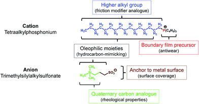
Since RTILs are prepared by combining cationic and anionic moieties, each part could be designed (synthesized) individually. Of the three cationic moieties primarily used for RTILs (1,3-dialkylimidazolium, tetraalkylammonium, and tetraalkylphosphonium),6 tetraalkylphosphonium has a number of advantages over the others:• Higher thermo-oxidative stability
• Availability of higher alkyl substituents through a simple preparative procedure
• The n-alkyl group has a structure analogous to that of friction modifiers
• Metal phosphate boundary film precursor21
• The presence of higher alkyl groups make the molecules hydrophobic and increase the hydrocarbon content, in line with the hydrocarbon-mimicking strategy.
As for the anionic moiety, fluorine-containing ones are used commonly. Fluorine is highly electronegative and if incorporated in a molecule, it stabilizes the negative charge on the molecule and makes the molecule hydrophobic through the substituent effect. Further, it forms strong covalent bonds with other atoms such as those of carbon, thereby improving the thermo-oxidative stability of the molecule. It also makes the molecule bulky, as its atomic radius is higher than that of hydrogen. Owing to these outstanding properties, fluorine-based anionic moieties are highly suited for use in RTILs. However, as mentioned previously, fluorine also exhibits a significant disadvantage with respect to tribological applications, in that it can cause tribo-induced corrosion. When considering fluorine alternatives that can endow a negative charge on molecules while also affording tribological benefits, we first investigated various pseudo-halogen functional groups.19 Then, in continuation of our previous work, we focused on alkyl oxoacids such as phosphates,22 sulfonates,23 and carboxylates. The alkyl group in these acids could be modified by changing the functional group(s). For instance, trimethylsilyl-substituted alkyl sulfonates have been introduced recently.24,25 The structural features of the anion as lubricant are the following:
• The sulfonate can act as an anchor, allowing the molecule to be adsorbed on metal surfaces by forming a boundary film
• The trialkylsilyl group has a structure corresponding to one with quaternary carbons and results in better rheological properties26
• The additional hydrocarbon units present on the silicon atom induce oleophilic and hydrophobic properties.
In addition, the phosphonium and trialkylsilyl units make the molecule bulky; this lowers the glass transition temperature of the resultant salts (RTILs). Based on this strategy, several RTILs were prepared from tetraalkylphosphonium chloride and sodium trimethylsilylalkylsulfonate, which are commercially available reagents, by a one-step metathesis process. The intended function of each moiety is shown in Fig. 1.
An alphanumeric code system (shown in Fig. 2) is used to distinguish between the different RTILs based on the tetraalkylphosphonium cation and the trialkylsilylalkylsulfonate anions. These novel RTILs are composed of the heteroatoms P (in cation), Si, S, and O (in anion), with various alkyl chains being attached to them. Therefore, the abbreviation P–SiSO is used hereafter when referring to these RTILs. This term is combined with a numeric system representing the carbon numbers of the alkyl chains. With respect to the cation, three of the four alkyl groups are the same. Therefore, α denotes the number of carbon atoms in the three identical alkyl groups, while β identifies the remaining alkyl group. In the case of the anion, χ denotes the three identical alkyl groups (normally methyl), while the carbon number of the alkene connecting the Si and S atoms is identified by δ. This leads to the alphanumeric code P–SiSO[α-β][χ-δ].
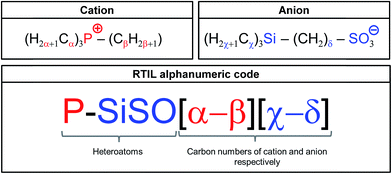 | ||
| Fig. 2 Alphanumeric code system employed for identifying the P–SiSO-type RTILs having alkyl chains with differing carbon numbers. | ||
Finally, an oleophilic index, IO, is introduced, in order to quantify the hydrocarbon content in the lubricants. The oleophilic index, IO, is defined as the ratio of the hydrocarbon content as determined based on the formula weight (see eqn (1)) and ranges from 0 to 1. In this equation, fw(H–C) is the formula weight of all hydrocarbons in the lubricant molecule(s), while fw(tot) is the total formula weight. Further, it was assumed that the tribosystem compatibility would increase with an increase in its value.
 | (1) |
3. Experimental
3.1 Lubricant properties
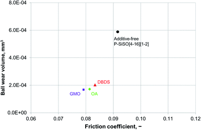
Two P–SiSOs were selected for evaluation in terms of the friction, wear, and corrosion properties: P–SiSO[4-12][1-2] and P–SiSO[4-16][1-2] (other examples given in the ESI†). Three lubricants with low vapor pressures were used as the references: the halogen-containing RTIL 1-butyl-3-methylimidazolium bis(trifluoromethane-sulfonyl)amide ([BMIM][TFSA]), and two different perfluoropolyether (PFPE) fluids, referred to as PFPE-L and PFPE-H. The former displays a low viscosity at room temperature while the latter show a higher viscosity. The densities, viscosities, and oleophilic index values of the neat fluids are listed in Table 1; their other properties are given in the ESI.†Three different additives were used in a concentration of 5 wt%, with P–SiSO[4-16][1-2] employed as the base fluid. There were glycerol monooleate (GMO), oleylamine (OA), and dibenzyl disulfide (DBDS). Of these, GMO and OA are conventional organic friction modifiers,1 while DBDS has a long history of use as an antiwear or extreme-pressure additive.27
3.2 Copper strip corrosion test
Polished copper strips were immersed in the P–SiSOs and then heated for a set period of time, in order to evaluate the corrosion properties of the P–SiSOs, in keeping with the guidelines of the ASTM D130-12 copper strip test. This standard uses a visual guide with four categories (1–4) for classifying the degree of corrosion, with category 1 corresponding to the lowest degree of corrosion (“slight tarnish”) and category 4 the highest degree (“corrosion”). The samples were tested at two temperatures, 150 and 200 °C, for a duration of 3 h each. These conditions were deliberately chosen to be more severe than the ones used normally (100 °C for 3 h) when evaluating hydraulic fluids or lubricating oils, in order to mimic harsh conditions. PFPE-L and PFPE-H were used as the reference fluids.3.3 Ball-on-flat reciprocating tribotest
An Optimol SRV tribotester in the ball-on-flat configuration was used to evaluate the lubrication performance of the P–SiSOs with respect to friction and wear. This involved continuously measuring the friction force and analyzing the post-tribotest wear scars. In this test, a 10 mm ball was pressed against the top of a flat stationary disc while being subjected to a linearly reciprocating motion with an amplitude of 1.0 mm and frequency of 50 Hz. The ball and disc were made of AISI 52100 steel, in keeping with the ASTM D6425-11 standard. All the tests were conducted in air, with the relative humidity being 25–50%. Three parameters were varied during the tests in this study: test duration, normal load, and test temperature (the temperature was controlled by heating the disc support). Before starting a test, a small amount of the lubricant being tested was applied on the disc at the area of contact.Three different test settings were used, in order to evaluate the tribological properties of the lubricants: (I) initial screening, (II) elevated load and temperature, and (III) additive compatibility. Depending on the objective of the test, the test conditions were either held constant or were varied during the test. The following code was used to indicate the conditions used in the various cases: C{L/T/D} or V{L1–L2/T1–T2/D}, where L, T, and D represent normal load, test temperature, and test duration respectively. The subscript 1 indicates the “minimum” value while 2 indicates the “maximum” value. The settings used for the various tribotest scenarios are listed in Table 2, while the details are given below.
| Test scenario | Test code |
|---|---|
| (I) Initial screening | C{100 N/25 °C/60 min} |
| C{150 N/25 °C/60 min} | |
| (II) Elevated load and temperature | V{100 N/25–100 °C/180 min} |
| V{100–300 N/25 °C/150 min} | |
| (III) Additive suitability | C{100 N/75 °C/60 min} |
The initial screening tests (I) were all conducted at constant load and room temperature (∼25 °C), with the test duration being 60 min. The load was held at either 100 N or 150 N and corresponded to a mean Hertzian pressure of 1.4 or 1.6 GPa, respectively. Therefore, the test conditions were presented as C{100 N/25 °C/60 min} and C{150 N/25 °C/60 min}, respectively.
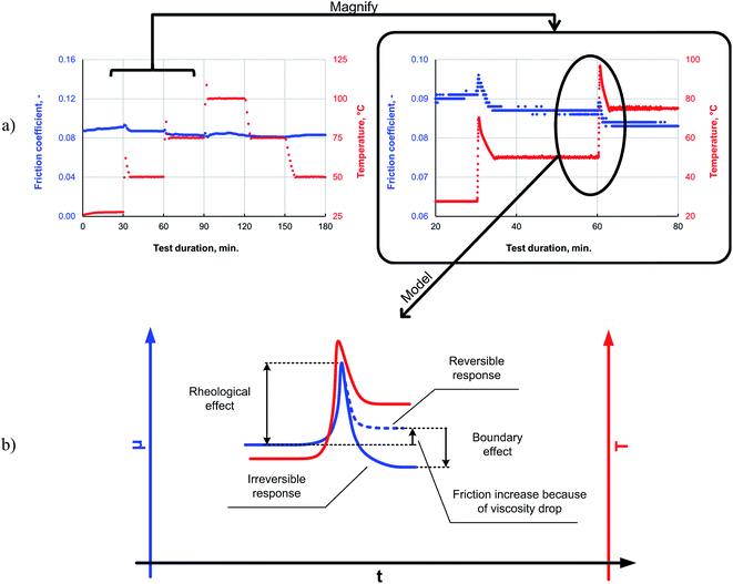
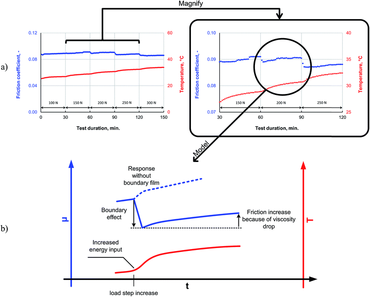
In test scenario (II), the lubricants were evaluated by varying the load or temperature in a stepwise manner. To study the lubricant response at elevated temperatures, the reciprocating tribotest was modified to include temperature cycling. The duration of the temperature cycling test was 180 min. During this period, the load was held constant at 100 N, as the temperature was increased in increments of 25 °C at intervals of 30 min, starting from room temperature. Then, 90–120 min into the test, the temperature was held at the maximum level of 100 °C. Next, the temperature cycle was reversed and the temperature was decreased in the same increments. Therefore, the test code for scenario (II) for elevated temperatures was V{100 N/25–100 °C/180 min}. For elevated loads during scenario (II), the test duration was 150 min, and the test was conducted at room temperature. During this time, the load was increased stepwise in increments of 50 N at intervals of 30 min over the course of the test. During the final 30 min of the test, the load was 300 N, which corresponded to a mean Hertzian pressure of 2.0 GPa. Therefore, the test code for scenario (II) for elevated loads was V{100–300 N/25 °C/150 min}.
Scenario (III) evaluated the applicability of the various additives in P–SiSO. A constant load of 100 N was applied for the entire test duration of 60 min, and the temperature was held constant at 75 °C to provide a slightly increased rate of reactivity. Thus, the test conditions for this scenario could be represented as C{100 N/75 °C/60 min}.
3.4 Quantification of wear volume
The degree of wear was quantified by means of wear scar analyses performed using optical profiling. The wear volume was calculated from the average wear scar diameter (WSD). However, because relatively small wear volumes were expected, it was assumed that the elastic deformation significantly influenced the results.28–30 Therefore, the wear volume (W) was defined as the volume of a spherical cap with a base diameter equal to the average WSD (VWSD), after the volume of the material displaced elastically (VHzD) had been subtracted (2). The latter was determined by a spherical cap with a base equal to the Hertzian contact diameter (HzD), which is the contact patch attributable to elastic deformation.31 Details can be found in the ESI.†| W = VWSD − VHzD | (2) |
4. Results and discussion
4.1 Copper strip corrosion test
As can be seen from Table 3, both of the P–SiSO lubricants evaluated could be classified as belonging to category 1 (slight tarnish) when exposed to 150 °C for 3 h, while the PFPE samples were classified as belonging to category 2b (moderate tarnish). In the second case, when the temperature was increased to 200 °C, the P–SiSOs were classified as 3a (dark tarnish). However, at this temperature, owing to the emission of excessive amounts of smoke, the tests on the PFPEs had to be aborted within the first 10 min. Therefore, the PFPE samples could not be classified in the case of elevated temperatures. Regarding the increase in the degree of tarnishing of the P–SiSO samples, it should be noted that the difference between the classifications 1a/b and 3a is marginal and that the shift from the classification “slight tarnish” to “dark tarnish” may be misleading. The key result to focus on is that none of the evaluated samples caused corrosion of the copper strips, indicating that the P–SiSOs can be classified as being noncorrosive to copper. Images of the exposed copper strips are given in the ESI.†| P–SiSO[4-12][1-2] | P–SiSO[4-16][1-2] | PFPE-L | PFPE-H | |
|---|---|---|---|---|
| 150 °C | 1b | 1a | 2b | 2b |
| 200 °C | 3a | 3a | Aborted | Aborted |
4.2 Tribological evaluation
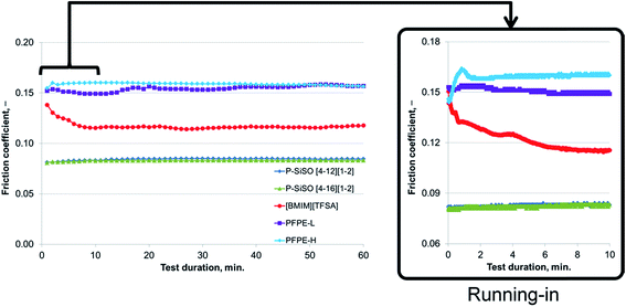
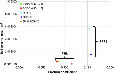
An ideal lubricant should minimize both friction and wear simultaneously. Fig. 4 shows plots of the ball wear volume against the mean friction coefficient for the five lubricants evaluated under conditions of C{100 N/25 °C/60 min}. Every data point shown represents the average value for a minimum of two tests. As was seen in Fig. 3 too, the P–SiSOs display the lowest mean friction coefficient, with the longer-alkyl-chain cation P–SiSO showing a slight advantage over the shorter-chain cation one. With respect to the ball wear volumes, there is a large spread in the data; PFPE-L results in significant wear, while the ionic liquids result in a small degree of wear. Further, PFPE-H results in considerably higher wear than that in the case of the P–SiSOs; however, it is not as high as that in the case of PFPE-L, which has a lower viscosity. It can thus be concluded that, with respect to friction and wear, the P–SiSOs displayed excellent performance under the conditions tested.
It should be noted that, at this ball wear scale, a zero ball wear volume indicates that the WSD is equal to the HzD. All the ionic liquids tested displayed barely distinguishable wear scars with diameters only a few percent larger than the Hertz diameter.
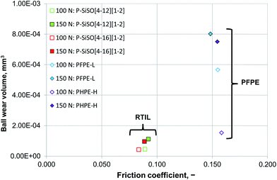
Increasing the load to 150 N had a negligible effect on the friction coefficients of the PFPE and P–SiSO lubricants. On the other hand, the effects on the wear volume were much more noticeable. In the case of PFPE-H, which resulted in a low wear volume at 100 N, the wear volume increased significantly at 150 N, as can be seen in Fig. 5. In the case of PFPE-L, which resulted in high wear even at 100 N, the wear volume increased further at 150 N, although at a slower rate compared to that for PFPE-H. The P–SiSOs showed similar behaviors, with both resulting in increased WSDs in the range 10–20% as well as a slight increase in friction.
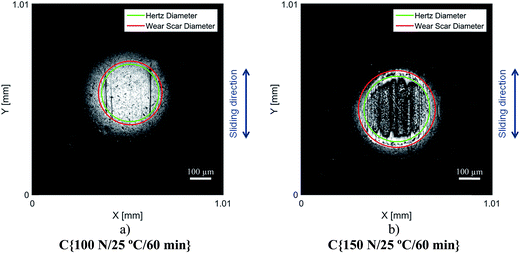
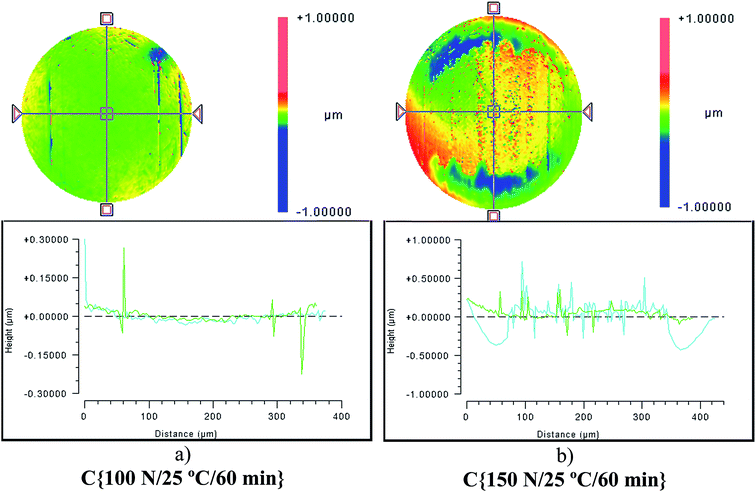
Although the wear scar diameters in the case of the P–SiSOs did not change considerably when the load was increased from 100 N to 150 N, the wear scar characteristics did. Fig. 6 shows the two different ball wear scars for P–SiSO[4-16][1-2] when subjected to tests under the conditions C{100 N/25 °C/60 min}, and C{150 N/25 °C/60 min}. The corresponding surface topography can be seen in Fig. 7. For a load of 100 N, the wear scar is defined by a mildly worn surface that includes a few light scratches along the sliding direction. The diameter of this mildly worn surface is very close to the Hertzian diameter, as can be seen in Fig. 6a, indicating that the surface was effectively protected. For a load of 150 N, the morphology is markedly different. The wear scar is defined by a thin annular groove with an inner diameter close to the Hertzian diameter and an outer ellipse that marks the border of the wear scar. Within this annular shape is a central section with shallow grooves in the sliding direction, indicating abrasive wear. Possibly, at low loads, the long alkyl chains in the cation function as friction modifiers, providing a sufficient load-carrying capacity to separate the surfaces, while at slightly higher loads, the phosphonium cation reacts to form metal phosphate boundary films.21
It can be seen from the data in Fig. 8 that, as the temperature is increased, the friction also increases initially; this behavior is typical for a system operating in the mixed lubrication regime. The friction increases as the lubricant viscosity decreases with the temperature, and the asperities increasingly come into contact with each other.33 However, after the overshoot, once the temperature and friction traces have plateaued at the programmed level, the friction reduces to a level lower than that measured at the previous temperature step. This irreversible decrease in the friction indicates the formation of a low-friction boundary film. Thus, elevated temperatures can be expected to promote boundary film formation, as a sufficient amount of activation energy for the tribochemical reaction is available at the higher temperatures.
The friction response of P–SiSO[4-16][1-2] to elevated loads is shown in Fig. 9. The applied load was increased every 30 min for 150 min in a stepwise manner, starting at a room temperature, during a reciprocating tribotest performed under the conditions V{100–300 N/25 °C/150 min}. The load was increased in a stepwise manner (∼5 s); there was no overshoot beyond the intended load. As can be seen from the friction trace in Fig. 9a, the friction coefficient decreases when the load is increased beyond 150 N. The lowest friction coefficient is observed at 300 N, which corresponds to a mean contact pressure of 2.0 GPa. In the mixed lubrication regime, an increased load can be expected to increase the friction, owing to a shift towards the boundary lubrication regime for two reasons: (i) an increase in the number of asperities coming in contact because of the increased contact pressure and (ii) a reduction in the lubricant viscosity owing to the increased temperature, which also leads to an increase in the number of asperities coming in contact. However, increasing the load also increases the likelihood of tribochemical reactions; the pressure in the contact increase with higher load, and the higher load also means that more friction power is dissipated as heat in the contact, as this is proportional to applied load, friction coefficient and sliding distance. For these reasons, the higher load may provide the P–SiSO lubricants the activation energy required for the tribochemical reactions for forming boundary films, which would affect the extent of friction. This could explain the observed reduction in friction. A possible mechanism to explain the observed resilience against high loads is that higher loads lead to the initial wear of the native oxide layer, exposing the nascent metal surface and thereby initiating the tribochemical reactions of the metal with the phosphonium or sulfonate moieties. Further, as no indicators of seizure were observed during the test, it can be concluded that the lubricants exhibited high load-carrying capacities.
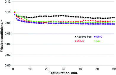 | ||
| Fig. 10 Compatibility of additives for use with P–SiSO[4-16][1-2] evaluated by the reciprocating tribotests performed under conditions of C{100 N/75 °C/60 min}. | ||
5. Conclusions
The molecular design of P–SiSOs, which are halogen-free RTIL base fluids, based on the concept of hydrocarbon-mimicking is described in this work. Tribological evaluations of the P–SiSOs suggested that they reduce friction and wear to significantly greater degrees as compared to reference PFPEs, as determined by steel-on-steel reciprocating tribotests performed under ambient conditions. Further evaluations of the P–SiSOs indicated that they show mild tribochemical reactivity. Formation of friction-reducing boundary films was indicated at elevated loads and temperatures, while no sign of corrosion was detected during tribotesting or static copper strip immersion testing. Finally, three different conventional oil additives were found to reduce friction and wear when combined with P–SiSO, indicating that it should be possible to improve their tribological performances as is the case with hydrocarbon base oil-additive systems.Author contributions
I. M. conceived and designed the project; C. Y. R. performed preliminary experiments; and E. N. performed most of the experiments and analysis and wrote the manuscript. All authors have given approval to the final version of the manuscript.Conflict of interest
The authors declare no competing financial interest.Abbreviations
| RTIL | Room-temperature ionic liquid |
| [BMIM][TFSA] | 1-Butyl-3-methylimidazolium bis(trifluoromethanesulfonyl)amide |
| PFPE | Perfluoropolyether |
| GMO | Glycerol monooleate |
| OA | Oleylamine |
| DBDS | Dibenzyl disulfide |
| WSD | Wear scar diameter |
| HzD | Hertzian contact diameter |
Acknowledgements
This work was funded by the “Austrian COMET-Program” in the frame of K2 XTribology (project no. 849109). The research work was carried out within the “Excellence Centre of Tribology” (AC2T research GmbH). The Taiho Kogyo Tribology Research Foundation (TTRF) also provided funding through the 2016 15B07 grant. E. N. acknowledges funding from the Graduate School of Space Technology at Luleå University of Technology.References
- H. Spikes, Tribol. Lett., 2015, 60, 1–26 CrossRef.
- H. Spikes, Tribol. Lett., 2004, 17, 469–489 CrossRef CAS.
- I. Minami, in Encyclopedia of Tribology, ed. Q. J. Wang and Y.-W. Chung, Springer, US, Boston, MA, 2013, pp. 1859–1866 Search PubMed.
- M. Deetlefs, M. Fanselow and K. R. Seddon, RSC Adv., 2016, 6, 4280–4288 RSC.
- C. Ye, W. Liu, Y. Chen and L. Yu, Chem. Commun., 2001, 2244–2245 RSC.
- I. Minami, Molecules, 2009, 14, 2286–2305 CrossRef CAS PubMed.
- M. D. Bermúdez, A. E. Jiménez, J. Sanes and F. J. Carrión, Molecules, 2009, 14, 2888–2908 CrossRef PubMed.
- F. Zhou, Y. Liang and W. Liu, Chem. Soc. Rev., 2009, 38, 2590–2599 RSC.
- M. Palacio and B. Bhushan, Tribol. Lett., 2010, 40, 247–268 CrossRef CAS.
- A. E. Somers, P. C. Howlett, D. R. MacFarlane and M. Forsyth, Lubricants, 2013, 1, 3–21 CrossRef.
- T. Torimoto, T. Tsuda, K. Okazaki and S. Kuwabata, Adv. Mater., 2010, 22, 1196–1221 CrossRef CAS PubMed.
- S. M. Hsu and R. S. Gates, Tribol. Int., 2005, 38, 305–312 CrossRef CAS.
- I. Minami and S. Mori, Lubr. Sci., 2007, 19, 127–149 CrossRef CAS.
- A. E. Jiménez, M. D. Bermúdez, F. J. Carrión and G. Martínez-Nicolás, Wear, 2006, 261, 347–359 CrossRef.
- A. E. Jiménez, M. D. Bermúdez, P. Iglesias, F. J. Carrión and G. Martínez-Nicolás, Wear, 2006, 260, 766–782 CrossRef.
- Y. Kondo, S. Yagi, T. Koyama, R. Tsuboi and S. Sasaki, Proc. Inst. Mech. Eng., Part J, 2012, 226, 991–1006 CrossRef CAS.
- B. S. Phillips, G. John and J. S. Zabinski, Tribol. Lett., 2007, 26, 85–91 CrossRef CAS.
- D. J. Carré and J. A. Markowitz, ASLE Trans., 1985, 28, 40–46 CrossRef.
- I. Minami, T. Inada and Y. Okada, Proc. Inst. Mech. Eng., Part J, 2012, 226, 891–902 CrossRef CAS.
- L. Zhang, D. Feng and B. Xu, Tribol. Lett., 2009, 34, 95–101 CrossRef.
- I. Minami, T. Inada, R. Sasaki and H. Nanao, Tribol. Lett., 2010, 40, 225–235 CrossRef CAS.
- V. Totolin, I. Minami, C. Gabler, J. Brenner and N. Dörr, Tribol. Lett., 2014, 53, 421–432 CrossRef CAS.
- L. Pisarova, V. Totolin, C. Gabler, N. Dörr, E. Pittenauer, G. Allmaier and I. Minami, Tribol. Int., 2013, 65, 13–27 CrossRef CAS.
- A. E. Somers, R. Yunis, M. B. Armand, J. M. Pringle, D. R. MacFarlane and M. Forsyth, Lubricants, 2016, 4, 1–12 CrossRef.
- A. E. Somers, B. Khemchandani, P. C. Howlett, J. Sun, D. R. MacFarlane and M. Forsyth, ACS Appl. Mater. Interfaces, 2013, 5, 11544–11553 CAS.
- C. E. Snyder Jr, L. J. Gschwender, C. Tamborski, G. J. Chen and D. R. Anderson, ASLE Trans., 1982, 25, 299–308 CrossRef.
- E. S. Forbes, Wear, 1970, 15, 87–96 CrossRef CAS.
- ASTM Standard G133-05: Standard Test Method for Linearly Reciprocating Ball-on-Flat Sliding Wear, 2010.
- M. Kalin and J. Vižintin, Wear, 2000, 237, 39–48 CrossRef CAS.
- E. P. Whitenton and P. J. Blau, Wear, 1988, 124, 291–309 CrossRef.
- Q. J. Wang and D. Zhu, in Encyclopedia of Tribology, ed. Q. J. Wang and Y.-W. Chung, Springer, US, Boston, MA, 2013, pp. 1647–1654 Search PubMed.
- B. Yu, F. Zhou, C. Pang, B. Wang, Y. Liang and W. Liu, Tribol. Int., 2008, 41, 797–801 CrossRef CAS.
- Y. Wang and Q. J. Wang, in Encyclopedia of Tribology, ed. Q. J. Wang and Y.-W. Chung, Springer, US, Boston, MA, 2013, pp. 3365–3370 Search PubMed.
Footnote |
| † Electronic supplementary information (ESI) available: Lubricant data regarding 5 P–SiSOs, 2 PFPEs, [BMIM][TFSA]. Details of wear volume calculation. Full results from P–SiSO copper strip immersion test including images. Tribotest results at C{100 N/25 °C/60 min} and C{150 N/25 °C/60 min}. See DOI: 10.1039/c6ra27065d |
| This journal is © The Royal Society of Chemistry 2017 |

