 Open Access Article
Creative Commons Attribution 3.0 Unported Licence
On-chip integration of organic synthesis and HPLC/MS analysis for monitoring stereoselective transformations at the micro-scale†
Josef J.
Heiland
a,
Rico
Warias
a,
Carsten
Lotter
a,
Laura
Mauritz
a,
Patrick J. W.
Fuchs
b,
Stefan
Ohla
a,
Kirsten
Zeitler
 b and
Detlev
Belder
*a
aInstitute of Analytical Chemistry, University of Leipzig, Linnéstr. 3, D-04103 Leipzig, Germany. E-mail: belder@uni-leipzig.de
bInstitute of Organic Chemistry, University of Leipzig, Johannisallee. 29, D-04103 Leipzig, Germany
First published on 23rd November 2016
Abstract
We present a microfluidic system, seamlessly integrating microflow and microbatch synthesis with a HPLC/nano-ESI-MS functionality on a single glass chip. The microfluidic approach allows to efficiently steer and dispense sample streams down to the nanoliter-range for studying reactions in quasi real-time. In a proof-of-concept study, the system was applied to explore amino-catalyzed reactions, including asymmetric iminium-catalyzed Friedel–Crafts alkylations in microflow and micro confined reaction vessels.
Continuous flow chemistry has emerged as a powerful alternative to common batch synthesis to facilitate transformations, which are difficult to conduct with conventional equipment.1–6 Microflow technology benefits from superior control over process parameters and even opens up entirely new routes and strategies for chemical synthesis and process optimization.7–18 While coil-, tube- or capillary-based reactors are already well established,19–21 chip-based devices offer unsurpassed potential for seamless system integration of various functionalities on a single device.22–26 Here, especially the combination of chemical transformations and on-the-fly or downstream analytical characterization offers unique insights into chemical processes.27–31 The latter can be realized rather simply by applying micro-spectroscopic techniques32 such as fluorescence or Raman microscopy or by coupling microfluidic chips to mass spectrometry.33,34 However, the selective analytical characterization can be quite challenging in the context of stereoselective conversions. We previously reported on the integration of microflow reactions and chip electrophoresis, which allowed to analyze enantioselective transformations.35–38 Chip electrophoresis is technically straightforward but has rather limited applications in organic synthesis.39 The current state of the art to analyze transformations in continuous micro-flow is using traditional macroscopic HPLC instruments40–42 as in classical laboratories. Although there is progress in chip-based high-performance liquid chromatography (HPLC),43–48 the combination of flow synthesis and high-pressure liquid chromatography on a single device is an unsolved challenge. Since the chip-integration of moving parts, like high-pressure valves, is a major obstacle, the interconnection of a low-pressure continuous flow channel with a HPLC column working at high pressure poses a challenge. This can be overcome if the flows are steered hydraulically with valves and flow restrictors in the outer chip periphery. This concept was applied for on-chip low pressure sample injection48–52 and more recently also for the connection of an external flow reactor via transfer capillaries to a 2D HPLC chip.53 A true integration of micro- or nano-reactors and a HPLC column on the same device is very attractive as it would allow to monitor chemical processes at smallest dimensions in real-time. Such integrated synthesis and analysis devices are foreseen as enabling technology for future chemical synthesis.54
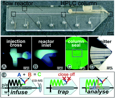
Herein, we present the first example for such a seamless integration of a micro reactor and a packed HPLC column on a single device, which is furthermore hyphenated to mass spectrometry (MS). This is achieved with a tailor-made glass device interconnecting reaction channel and chromatography column in a dead-volume free manner, as schematically shown in Fig. 1. We developed a fluid flow steering method, which enables to dispense nano-liter sized portions of continuous flow as well as micro-batch reactors onto an adjacent HPLC-column.
 | ||
| Fig. 1 Schematic representation of the workflow for the direct coupling of microflow synthesis and chiral HPLC-MS analysis on a single microfluidic device. | ||
A photograph of the chip together with microscopic images of key elements such as the transfer cross, the reactor inlet, the sealed column and the electrospray ionization (ESI)-emitter are displayed in Fig. 2. The microchannel layout comprises a 500 nl meandering flow reactor structure connected to a 35 mm packed-bed chromatographic column via a microfluidic cross junction.
The chromatographic column was generated via common slurry packing through a packing channel, which is sealed thereafter with a photopolymer as described earlier, see Fig. 2(C). This column manufacturing process50 allows for the integration of any commercially available HPLC phase material including chiral stationary phases for enantioselective separations. The similarity to common HPLC-technology greatly facilitates a straightforward method transfer to or from experiments at laboratory scale. At the end of the separation channel a monolithic nanospray emitter for online ESI-MS coupling is implemented. A key functional element of our device is the microfluidic intersection, where the reactor outlet and the column head join, as it enables the crucial sample transfer of the reaction mixture to the HPLC-column. For this purpose, the pressure stable glass chip is connected to peripherals such as pumps and valves via home-made steel connection clamps allowing for low dispersion fluidic interfacing at up to 350 bar.55 This allows for a controlled steering of the different microflows in an automated way. A detailed technical description of the set-up is provided in the ESI† (see Fig. SI-1 and SI-2).
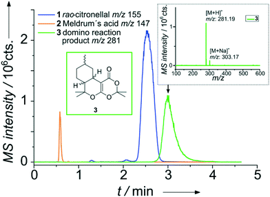
A representative result for the successful on-chip combination of a micro flow reactor and a HPLC separation is shown in Fig. 3. In brief, two reagent streams A and B are merged on-chip and traverse the meandering flow reactor channel. Mixing of the reagents was evaluated with the aid of model dyes and fluorescence microscopy, which proofed mixing within the first 70 nl (see Fig. SI-7†). A portion of the reaction mixture bypassing the injection cross is then transferred by a low pressure sample injection scheme51 to the adjacent particulate column. After chromatographic separation of the reaction mixture, detection is performed via nano-ESI-MS.
The chip layout features an optional make-up flow channel, not used in this study, to facilitate mass spec detection with various eluents.52
As a first proof-of-concept, the device was applied to study a catalyzed Knoevenagel condensation of an aldehyde and a 1,3-diketone followed by an intramolecular hetero-Diels–Alder reaction (Scheme 1).56
For realizing this continuous flow domino reaction, a solution of citronellal 1 (0.1 mol l−1 in 80/20 vol% MeOH/H2O) as well as a mixture of Meldrum's acid 2 (0.12 mol l−1 in 80/20 vol% MeOH/H2O) with EDDA (10 mol% with respect to 2) as catalyst were introduced in the reactor unit at a flow rate of 10 μl min−1. The flow reactor was then probed with the integrated HPLC column with subsequent MS detection as described above. A representative result for a residence time of 5.4 seconds in the flow reactor is shown in Fig. 3 in terms of a MS chromatogram. Although the sample concentration was rather high, baseline separation of all components was achieved. The excellent chromatographic performance of the column is also evident from the high plate number 3500 (100![[thin space (1/6-em)]](https://www.rsc.org/images/entities/char_2009.gif) 000 plates m−1) for the first eluting peak.
000 plates m−1) for the first eluting peak.
After this initial proof of concept, we further applied the approach to optimize reaction conditions on the microscale. As an example, we studied the effect of the catalyst loading on the reaction by sequential introduction of sample solutions with different EDDA concentrations. As expected, higher catalyst amounts resulted in increased product formation. The results of these set of experiments are summarised in Fig. SI-5, ESI.† Unlike to the more common simple coupling of a flow reactor directly to mass spectrometry the integrated HPLC functionality allows to distinguish between isomeric products with identical mass,57 which is evident from Fig. SI-5,† where even diastereomeric products (m/z 281.19) are well resolved.
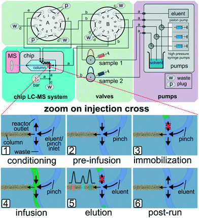
In the above mentioned setup the residence time in the microreactor is determined by the applied sample pump flow rates. At very low flow rates it proved difficult to reliably generate narrow sample plugs on the column head. At such slow reactor flows peak broadening was observed, which can be explained by diffusion or migration of sample components onto the column. Due to the limitations of the current flow steering process based on earlier work,51,52 we further developed the approach by effectively separating reactor fluid flow manipulations and the injection process to enable micro-batch operation with stopped flow. For this purpose we redesigned and upgraded the outer chip periphery by the addition of pumps, valves and interconnecting tubing. A schematic drawing of the setup and simplified sketches of the working principle are shown in Fig. 4.
By directed valve switching, this set-up enables to trap the reaction mixture inside the integrated 500 nl sized reactor channel in a way, that it is not in direct contact with the column head. By switching to injection mode, portions of the reaction mixture can be transferred onto the separation column on demand (see Fig. 4 bottom). In detail, after conditioning the column and reverse flushing the reactor (1), the sample streams are directed to the reactor compartment (2), where they are trapped hydrodynamically by sealing off the inlet ports (3). After the desired reaction time, portions of the reactor effluent can be infused to the column head (4) by pulsed valve switching. The injected amount is eluted over the column while the confined residual reactor content remains unaffected (5). Steps (4) and (5) may be repeated for multiple sequential sampling from the reactor (see Fig. 5). After the experiments, the column and the reactor are put back in conditioning mode (6) and all sample carrying parts are flushed in reverse to prevent cross contamination. Detailed technical information on this enhanced valving procedure is provided in the ESI† (see Fig. SI-8).
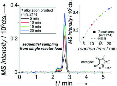 | ||
| Fig. 5 Overlapped EICs (m/z 214) of the alkylation product for sequential sampling of the iminium-catalyzed Friedel–Crafts alkylation see Scheme SI-1† with catalyst 2 (8) from a single reactor load. Based on injection valve switching profile see Table SI-5.† Column: ProntoSIL C18 SH, particle diameter 3 μm, length 35 mm. Mobile phase: 100 μl min−1, MeOH/H2O (60/40 vol%) with 0.1% formic acid. Sample pumps: 10 μl min−1, MeOH/H2O (80/20 vol%), pinch: 10 μl min−1, MeOH/H2O (50/50 vol%), reactant inlet A: 4 (0.1 mol l−1), reactant inlet B: 5 (0.05 mol l−1), 20 mol% 6 or 8 (in relation to 5) each in ACN/H2O (87/13 vol%). 19 bar elution pressure at the injection cross with immobilized sample plug, at a linear flow rate of 1.09 mm s−1 over the column. The isobaric shoulder peak is most probably due to a second, intramolecular Friedel–Crafts alkylation in the acidic environment of the eluent system containing 0.1 vol% formic acid. | ||
This novel set-up now allowed to study much slower reactions and was exemplarily applied to analyze an enantioselective iminium-catalyzed Friedel–Crafts alkylation of methyl pyrrole 4 and cinnamaldehyde 5 with two different chiral imidazolidinone-based catalysts 6 and 8 (see Scheme SI-1†).58–60
For this purpose, the two sample streams (inlet A: pyrrole 4, inlet B: aldehyde 5 with catalyst 6) were introduced into the chip. The combined sample stream was stopped just before it reached the column head and a small portion of the mixture was dispensed on-demand. In the current setup, the 500 nl reactor was filled from two 3.68 μl loops, a further reduction in volume is feasible. This dispensing process enables even multiple injections of about 100 nl portions from the 500 nl-sized microreactor. The result of a set of four experiments where the 500 nl reactor is consecutively sampled at 5 minute intervals is shown in Fig. 5. As evident from the data, an increase in reaction time results in an improved turnover as expected. This allows detailed kinetic studies of stereoselective reactions performed in micro-confined reactors as displayed in Fig. SI-8 to SI-15 in the ESI.†
The improved application range of this approach is evident from Fig. 6. While the product was not detectable applying the previous continuous flow conditions, a significant amount of the desired product can be analyzed after trapping the reaction mixture for 6.7 minutes.
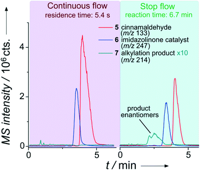 | ||
| Fig. 6 Extracted ion chromatograms of the separation of an enantioselective iminium-catalyzed Friedel–Crafts alkylation (see Scheme SI-1†) for two injections during a single run with chiral chip-HPLC. Column: Chiralpak IA-5, particle diameter 5 μm, length 35 mm. Mobile phase: 50 μl min−1, MeOH/H2O (60/40 vol%) with 0.1% formic acid. Sample pumps: 10 μl min−1, MeOH/H2O (80/20 vol%). Pinch: 10 μl min−1, MeOH/H2O (50/50 vol%). 8 bar elution pressure at the injection cross with immobilized sample plug at a linear flow rate of 0.88 mm s−1 over the column. Reactant inlet A: 4 (0.25 mol l−1), reactant inlet B: 5 (0.25 mol l−1), 10 mol% 6 (in relation to 5) each in ACN/H2O (87/13 vol%). | ||
As evident from Fig. 6, it is even possible to differentiate the enantiomers in the reaction solution since we equipped the device with a chiral stationary phase (Chiralpak IA-5, 5 μm diameter Chiral Technologies Europe, Daicel Corp., Osaka, Japan). A further improvement of the currently rather low chromatographic enantiomer resolution of 0.8 should be straightforward by using an adapted channel layout with an increased column length and smaller diameter phase material. In a set of semi-automated experiments (valve switching pattern see Table SI-5†), we applied the stop-flow approach to kinetic investigations of the alkylation product formation, utilizing two different catalysts at 20 mol% (with respect to 5) as well as a negative control. The results are shown in Fig. SI-16,† revealing the benefit of catalyst A (6), which is in good agreement with respective control batch experiments. No product formation was observed in the absence of a catalyst after 30 min reaction time. Although the sample concentrations in these reaction-monitoring experiments are typically rather high, we briefly evaluated the sensitivity of the system. Considering a signal-to-noise (S/N) ratio for the main fragment of cinnamaldehyd of about 3000, the detection of even low nano-molar concentrations should be easily reached with this not-optimized set-up.
In conclusion, we have introduced a novel approach for the seamless integration of chemical reactions in micro-flow and micro-batch conditions, HPLC separation and electrospray ionization in one single microfluidic chip. With this approach chemical transformations at the microscale can be followed by LC-MS in quasi real time and great detail.
In future work, eluent compatibility limitations can be overcome by integrating trapping columns and multi-dimensional separation techniques. Such integrated reaction and analysis devices allow rapid studies of a great variety of chemical transformations like enantioselective catalysis. This novel tool is ideally suited for (automated) investigations of novel reactions, synthesis optimization and catalyst screening at high speed and minimal resource consumption. Thereby, the setup offers great potential as a “smart” automated system61 using feedback from on-chip LC-MS to explore and optimize reactions at the microscale for high-throughput screening applications like in drug development or medical diagnostics.
Experimental section
Glass chips (borosilicate BF®33 – dimensions: 45 mm length × 10 mm width × 2.2 mm height, semi-circular channels: 130 μm or 155 μm in width and 45 μm in depth) were produced by iX-factory (Dortmund, Germany, now part of micronit) by common photolithography, wet etching, powder-blasting and bonding methods according to our design specifications. The column head and outlet featured a slight narrowing to aid in the column generation process.In the valve scheme presented in Fig. 4 for continuous flow operation without the possibility of trapping the reaction mixture, valve ‘A’ may be removed and ports 9 and 10 are then connected to the two reactor inlets at the microchip. The high-pressure syringe pumps were connected to the microfluidic circuitry with 1/16′′ PEEK tubing with 120 μm ID, inline filters (2 μm SST frit) and adapters to fit 360 μm OD PEEK capillary tubing (all in grey box on the right). The remaining microfluidic setup consisted of 360 μm OD PEEK capillary tubing of differing IDs and lengths: a) 75 μm, 20 cm; b) 50 μm 15 cm; c) 50 μm 60 cm; d) 50 μm 30 cm; e) 50 μm 13 cm; f) 50 μm 14.5 cm. The injection loops each had a volume of 3.68 μl. Further detailed experimental information is given in the ESI.†
This work was supported by the Studienstiftung des dt. Volkes (PhD scholarship J. J. Heiland), Chiral Technologies Europe (esp. Dr. Pilar Franco, providing support and chiral stationary phase material) and the Deutsche Forschungsgemeinschaft (DFG) for funding (FOR 2177).
Notes and references
- C. Wiles and P. Watts, Green Chem., 2014, 16, 55 RSC.
- F. G. Finelli, L. S. M. Miranda and R. O. M. A. de Souza, Chem. Commun., 2015, 51, 3708 RSC.
- B. Gutmann, J.-P. Roduit, D. Roberge and C. O. Kappe, Angew. Chem., Int. Ed., 2010, 49, 7101 CrossRef CAS PubMed.
- A. Abou-Hassan, O. Sandre and V. Cabuil, Angew. Chem., Int. Ed., 2010, 49, 6268 CrossRef CAS PubMed.
- I. R. Baxendale, J. Chem. Technol. Biotechnol., 2013, 88, 519 CrossRef CAS.
- T. Noël and S. L. Buchwald, Chem. Soc. Rev., 2011, 40, 5010 RSC.
- J. Wegner, S. Ceylan and A. Kirschning, Adv. Synth. Catal., 2012, 354, 17 CrossRef CAS.
- V. Hessel, D. Kralisch, N. Kockmann, T. Noël and Q. Wang, ChemSusChem, 2013, 6, 746 CrossRef CAS PubMed.
- R. L. Hartman, J. P. McMullen and K. F. Jensen, Angew. Chem., Int. Ed., 2011, 50, 7502 CrossRef CAS PubMed.
- J. E. Kreutz, A. Shukhaev, W. Du, S. Druskin, O. Daugulis and R. F. Ismagilov, J. Am. Chem. Soc., 2010, 132, 3128 CrossRef CAS PubMed.
- A. G. O'Brien, Z. Horváth, F. Lévesque, J. W. Lee, A. Seidel-Morgenstern and P. H. Seeberger, Angew. Chem., Int. Ed., 2012, 51, 7028 CrossRef PubMed.
- R. J. Ingham, C. Battilocchio, D. E. Fitzpatrick, E. Sliwinski, J. M. Hawkins and S. V. Ley, Angew. Chem., Int. Ed., 2015, 54, 144 CrossRef CAS PubMed.
- H. R. Sahoo, J. G. Kralj and K. F. Jensen, Angew. Chem., Int. Ed., 2007, 46, 5704 CrossRef CAS PubMed.
- F. Lévesque and P. H. Seeberger, Angew. Chem., Int. Ed., 2012, 51, 1706 CrossRef PubMed.
- F. T. G. van den Brink, L. Büter, M. Odijk, W. Olthuis, U. Karst and A. van den Berg, Anal. Chem., 2015, 87, 1527 CrossRef CAS PubMed.
- K.-I. Min, T.-H. Lee, C. P. Park, Z.-Y. Wu, H. H. Girault, I. Ryu, T. Fukuyama, Y. Mukai and D.-P. Kim, Angew. Chem., Int. Ed., 2010, 49, 7063 CrossRef CAS PubMed.
- S. Kundu, A. S. Bhangale, W. E. Wallace, K. M. Flynn, C. M. Guttman, R. A. Gross and K. L. Beers, J. Am. Chem. Soc., 2011, 133, 6006 CrossRef CAS PubMed.
- K. Gilmore and P. H. Seeberger, Chem. Rec., 2014, 14, 410 CrossRef CAS PubMed.
- T. Rodrigues, P. Schneider and G. Schneider, Angew. Chem., Int. Ed., 2014, 53, 5750 CrossRef CAS PubMed.
- A. Nagaki, K. Imai, S. Ishiuchi and J.-i. Yoshida, Angew. Chem., Int. Ed., 2015, 54, 1914 CrossRef CAS PubMed.
- S. Stockinger, J. Gmeiner, K. Zawatzky, J. Troendlin and O. Trapp, Chem. Commun., 2014, 50, 14301 RSC.
- A. J. deMello, Nature, 2006, 442, 394 CrossRef CAS PubMed.
- D. Belder, Angew. Chem., Int. Ed., 2009, 48, 3736 CrossRef CAS PubMed.
- M. L. Kovarik, D. M. Ornoff, A. T. Melvin, N. C. Dobes, Y. Wang, A. J. Dickinson, P. C. Gach, P. K. Shah and N. L. Allbritton, Anal. Chem., 2013, 85, 451 CrossRef CAS PubMed.
- Y. Wang, W.-Y. Lin, K. Liu, R. J. Lin, M. Selke, H. C. Kolb, N. Zhang, X.-Z. Zhao, M. E. Phelps, C. K. F. Shen, K. F. Faull and H.-R. Tseng, Lab Chip, 2009, 9, 2281 RSC.
- S. J. Haswell, Nature, 2006, 441, 705 CrossRef CAS PubMed.
- S. Stockinger, J. Troendlin, F. Rominger and O. Trapp, Adv. Synth. Catal., 2015, 357, 3513 CrossRef CAS.
- K. S. Elvira, X. C. I. Solvas, R. C. R. Wootton and A. J. deMello, Nat. Chem., 2013, 5, 905 CrossRef CAS PubMed.
- V. Sans and L. Cronin, Chem. Soc. Rev., 2016, 45, 2032 RSC.
- K. F. Jensen, B. J. Reizman and S. G. Newman, Lab Chip, 2014, 14, 3206 RSC.
- M. Rasheed and T. Wirth, Angew. Chem., Int. Ed., 2011, 50, 357 CrossRef CAS PubMed.
- J. Yue, J. C. Schouten and T. A. Nijhuis, Ind. Eng. Chem. Res., 2012, 51, 14583 CrossRef CAS.
- X. Feng, B.-F. Liu, J. Li and X. Liu, Mass Spectrom. Rev., 2015, 34, 535 CrossRef CAS PubMed.
- X. Wang, L. Yi, N. Mukhitov, A. M. Schrell, R. Dhumpa and M. G. Roper, J. Chromatogr. A, 2015, 1382, 98 CrossRef CAS PubMed.
- K. M. Krone, R. Warias, C. Ritter, A. Li, C. G. Acevedo-Rocha, M. T. Reetz and D. Belder, J. Am. Chem. Soc., 2016, 138, 2102 CrossRef CAS PubMed.
- D. Belder, M. Ludwig, L. W. Wang and M. T. Reetz, Angew. Chem., Int. Ed., 2006, 45, 2463 CrossRef CAS PubMed.
- S. Ohla, R. Beyreiss, S. Fritzsche, P. Glaser, S. Nagl, K. Stockhausen, C. Schneider and D. Belder, Chem. – Eur. J., 2012, 18, 1240 CrossRef CAS PubMed.
- S. Fritzsche, S. Ohla, P. Glaser, D. S. Giera, M. Sickert, C. Schneider and D. Belder, Angew. Chem., Int. Ed., 2011, 50, 9467 CrossRef CAS PubMed.
- J. Hereijgers, T. Breugelmans and W. DeMalschea, J. Chem. Technol. Biotechnol., 2015, 90, 2122 CrossRef CAS.
- A. Odedra and P. H. Seeberger, Angew. Chem., Int. Ed., 2009, 48, 2699 CrossRef CAS PubMed.
- A. Buitrago Santanilla, E. L. Regalado, T. Pereira, M. Shevlin, K. Bateman, L.-C. Campeau, J. Schneeweis, S. Berritt, Z.-C. Shi, P. Nantermet, Y. Liu, R. Helmy, C. J. Welch, P. Vachal, I. W. Davies, T. Cernak and S. D. Dreher, Science, 2015, 347, 49 CrossRef CAS PubMed.
- J. P. McMullen, M. T. Stone, S. L. Buchwald and K. F. Jensen, Angew. Chem., Int. Ed., 2010, 49, 7076 CrossRef CAS PubMed.
- G. Desmet and S. Eeltink, Anal. Chem., 2013, 85, 543 CrossRef CAS PubMed.
- J. P. Kutter, J. Chromatogr. A, 2012, 1221, 72 CrossRef CAS PubMed.
- J. Xie, Y. Miao, J. Shih, Y.-C. Tai and T. D. Lee, Anal. Chem., 2005, 77, 6947 CrossRef CAS PubMed.
- P. A. Levkin, S. Eeltink, T. R. Stratton, R. Brennen, K. Robotti, H. Yin, K. Killeen, F. Svec and J. M. J. Fréchet, J. Chromatogr. A, 2008, 1200, 55 CrossRef CAS PubMed.
- J. Šesták, D. Moravcová and V. Kahle, J. Chromatogr. A, 2015, 1421, 2 CrossRef PubMed.
- D. Geissler, J. J. Heiland, C. Lotter and D. Belder, Microchim. Acta, 2016 DOI:10.1007/s00604-016-2012-3.
- S. Thurmann, A. Dittmar and D. Belder, J. Chromatogr. A, 2014, 1340, 59 CrossRef CAS PubMed.
- S. Thurmann, L. Mauritz, C. Heck and D. Belder, J. Chromatogr. A, 2014, 1370, 33 CrossRef CAS PubMed.
- S. Thurmann, C. Lotter, J. J. Heiland, B. Chankvetadze and D. Belder, Anal. Chem., 2015, 87, 5568 CrossRef CAS PubMed.
- C. Lotter, J. J. Heiland, S. Thurmann, L. Mauritz and D. Belder, Anal. Chem., 2016, 88, 2856 CrossRef CAS PubMed.
- C. Lotter, E. Poehler, J. J. Heiland, L. Mauritz and D. Belder, Lab Chip, 2016 10.1039/c6lc01138a.
- D. E. Fitzpatrick, C. Battilocchio and S. V. Ley, ACS Cent. Sci., 2016, 2, 131 CrossRef CAS PubMed.
- C. Lotter, J. J. Heiland, V. Stein, M. Klimkait, M. Queisser and D. Belder, Anal. Chem., 2016, 88, 7481 CrossRef CAS PubMed.
- M. Fernandez-Suarez, S. Y. F. Wong and B. H. Warrington, Lab Chip, 2002, 2, 170 RSC.
- L. F. Tietze, S. Brand, T. Brumby and J. Fennen, Angew. Chem., Int. Ed. Engl., 1990, 29, 665 CrossRef.
- N. A. Paras and D. W. C. MacMillan, J. Am. Chem. Soc., 2001, 123, 4370 CrossRef CAS PubMed.
- J. F. Austin and D. W. C. MacMillan, J. Am. Chem. Soc., 2002, 124, 1172 CrossRef CAS PubMed.
- R. Khajuria, S. Dham and K. K. Kapoor, RSC Adv., 2016, 6, 37039 RSC.
- B. J. Reizman and K. F. Jensen, Chem. Commun., 2015, 51, 13290 RSC.
Footnote |
| † Electronic supplementary information (ESI) available: Experimental details on microchip fabrication and operation, the microfluidic setup and supporting measurements. See DOI: 10.1039/c6lc01217e |
| This journal is © The Royal Society of Chemistry 2017 |

