 Open Access Article
Understanding metal–organic frameworks for photocatalytic solar fuel production
J. G.
Santaclara
,
F.
Kapteijn
 ,
J.
Gascon
 * and
M. A.
van der Veen
*
Catalysis Engineering, Department of Chemical Engineering, Delft University of Technology, van der Maasweg 9, Delft, 2629 HZ, The Netherlands. E-mail: j.gascon@tudelft.nl; m.a.vanderVeen@tudelft.nl
First published on 31st January 2017
Abstract
The fascinating chemical and physical properties of MOFs have recently stimulated exploration of their application for photocatalysis. Despite the intense research effort, the efficiency of most photocatalytic MOFs for solar fuel generation is still very modest. In this highlight we analyse the current status of the field and stress the potential of advanced spectroscopic techniques to gain structural and mechanistic insight and hence support the future development of MOFs to harvest and store solar energy.
Introduction
It is no wonder that mankind has been intrigued for quite a long time by the effect of light on materials. Inspired by natural photosynthesis as the greatest chemical factory of mother Nature, photocatalysis has been studied by several generations of scientists as a promising method for energy production, the so-called artificial photosynthesis. It was already more than a century ago when Ostwald, the founder of modern catalysis, stressed the relevance of these photocatalytic processes in nature, identifying them as the “mill of life”.1However, it was not until 1972 when the first example of photocatalytic energy generation, namely photocatalytic water splitting, was reported.2 Since then, different kinds of materials, i.e. semiconductors, metal-doped zeolites and metal complexes, have been intensively studied to boost artificial photosynthesis.3–6 Still, most known catalysts are based on expensive noble metals; their activities in the visible range of the spectrum achieved so far are low, and problems like fast back-electron transfer and recombination considerably decrease their efficiency. Therefore, artificial photosynthesis, where light absorption, charge funnelling, and subsequent utilization in redox reactions are performed by different sets of molecules arranged in a complex system, stands at the intersection between the urgent drive for sustainable energy sources and state-of-the-art nanomaterial engineering.
Metal–organic frameworks (MOFs) are newly emerged functional inorganic–organic hybrid materials. MOFs consist of long range ordered crystalline lattices built up of organic linkers and inorganic secondary building units (metal ions or clusters). Early enthusiasm about MOFs took advantage of their molecular nature and extreme porosity, focussing on applications, considered “classical” nowadays, like gas storage and separation.7–10 More recently, increasing attention has been paid to the electronic nature of MOFs and the opportunities to use them as light-harvesting mimics of natural photosynthesis for solar fuel production. The resemblance between MOFs and bulk transition metal oxides encouraged more than a decade ago the first examples of photocatalytic MOFs.11–15 Since then, frameworks based on Ti,16–18 Zr,19–24 Fe,25,26etc. have been reported for different artificial photosynthetic reactions (i.e. hydrogen evolution, carbon dioxide reduction and organic transformations).27–29 In this context, different approaches have been recently followed: from the use of MOFs as containers for encapsulating light absorbing photocatalysts22,24,30 to exploiting ligand-to-metal charge transfer (LMCT) within the MOF or even inducing charge transfer from the MOF to encapsulated catalysts.29,31 Regardless of the promising discoveries made in the past few years, a lot of progress is still needed.
Proof of the interest in this application of MOFs is the unprecedented number of reviews (almost as many as the number of papers on the topic) that have appeared in the literature over the last two years.31–36 In this highlight article, we do not intend to again review the state of the art, but rather to encourage research in this field towards understanding the optoelectronic properties of MOFs. We place special emphasis on recent advances in this direction and finally outline future directions for the design of more efficient MOFs for solar fuel production.
Electronic structure of the main photocatalytic MOFs
Semiconductor versus insulator nature
Based on their optical transitions and prospective electro/photochemical activity, MOFs have been labelled for many years as semiconductors. However, nowadays it is well accepted that, in general, they are insulator materials.32,37,38 This is due to, on the one hand, the inadequate energy level alignment of ligand and metal orbitals. Typically, organic ligands possess HOMO (highest occupied molecular orbital)–LUMO (lowest unoccupied molecular orbital) gaps above 3 eV. This makes it less likely that a metal centre will have energy levels that align with those of the ligand. On the other hand, the metal and ligand orbital symmetry mismatch often results in an electronic structure analogous to that only of the linker or the metal. Therefore, the way that organic molecules link metal centres in the majority of MOFs results in localized electronic states, which typically prevents efficient charge transport through the framework. Accordingly, MOFs should be seen as an array of self-assembled molecular entities, which are best defined in terms of the crystal equivalent of molecular orbitals – HOCO (highest occupied crystal orbital) and LUCO (lowest unoccupied crystal orbital) – rather than band-like states (conduction and valence bands).Despite the fact that stimulating examples on conductor MOFs have been very recently reported,39 none of these have been applied yet in photocatalysis for solar fuel production. This means that so far the MOFs studied for this application are insulators. Hence, we discuss their properties further within that frame.
Applying “push–pull” principles by ligand engineering
Many attempts have been made to push MOFs' light absorption into the visible region of the spectrum targeting efficient solar energy utilization. Since one of the most appealing properties of MOFs for photocatalysis is the easy tuneability of their light harvesting properties, ligand engineering has been intensively used to alter their electronic structure by modifying the orbital composition (Fig. 1) and, consequently, the chemistry of the HOCO–LUCO band edges.14,40,41 Considering that in most MOFs at least one of these frontier bands (HOCO and LUCO) is centred on the ligand, and that this is usually an organic conjugated molecule, their electron energies are tuneable and certainly influenced by the electron donating/withdrawing character of additional substituents (push–pull effect). Initially predicted by Civalleri,42 this effect was, for the first time, experimentally demonstrated with different organic bidentate ligands in the isoreticular IRMOF series.14 Afterwards, the introduction of primary amines has also been reported as a powerful strategy to sensitize various frameworks to visible light. Amino substituents on the ligand provide in many cases the lone pair of nitrogen for the interaction with the π*-orbitals of the benzene ring, donating electron density to the antibonding orbitals.43 In this context, the amino functionalization of MIL-125(Ti) and UiO-66(Zr), two originally deep-UV absorbing MOFs, resulted in an enhancement of electron density and a lowering of the ionization potential by raising the HOCO energy level and bringing absorption to the visible region.27,44 The addition of a second amino-group in the linker of MIL-125(Ti) was calculated to follow a similar trend.40 However, introducing the desired functionalization in a framework of choice is not always synthetically feasible;45 therefore post-synthetic modification strategies were required and successfully employed.46,47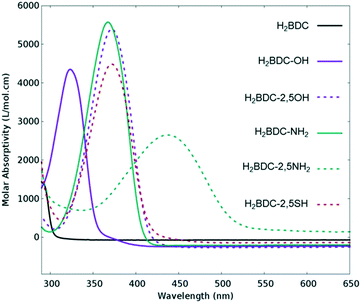 | ||
| Fig. 1 Experimental UV/VIS absorption spectra of different ligands used for the synthesis of UiO-66 frameworks for photocatalysis. Adapted with permission from ref. 41. Copyright 2015 American Chemical Society. | ||
HOCO/LUCO gap estimation
Notably, enhancing sunlight uptake is only worth it when the photogenerated charges meet two fundamental requirements: 1) possess sufficient redox potentials for driving the desired chemistry and 2) are located on atoms or molecule fragments that facilitate the charge transfer. Regarding the former requisite, the HOCO/LUCO gap estimation is often obtained from UV/VIS absorption spectroscopy. However, it does not provide the absolute energy level of HOCO and LUCO. Importantly, electrochemical experiments are capable of giving this vital information. By definition, electrochemistry comprises the transfer or storage of electrons at the interface of the electrode–electrolyte. In addition, due to their poor electron-conductivity, MOFs are rarely used as electrode materials,48 and the interpretation and discovery of the nature of the active sites from electrochemical measurements are not trivial.49 Conversely, MOFs in which charge and mass transport and active-site density are precisely controlled offer new avenues for electrochemistry and electrocatalysis. An excellent example was reported for electrocatalytic CO2 reduction, where MOF porous thin films were integrated into a conductive support.50In general, an electrochemical experiment entails the measurement of current when a potential difference is applied between two metal electrodes (working electrode, sensitive to the analyte concentration, and counter electrode, which closes the circuit) immersed in a chemical solution. Via a reference electrode (whose potential remains constant) the potential of the working electrode can be measured.51
However, few electrochemical studies have been reported to date on photocatalytic MOFs due to their insulating nature. Normally, deposition on the conducting material (e.g. ITO, indium tin oxide/FTO, fluorine doped tin oxide) is necessary and the choice of the right electrolyte (and buffer solution) is not trivial.
An indirect way to obtain electrochemical insights into insulating photocatalytic MOFs is by the study of the redox potentials of their molecular components: organic linker and metal oxocluster.52 Obviously, this is just an approximate estimation, and detailed experimental protocols should be described for electrochemistry with MOFs. In addition, DFT calculations have also proven to be effective in shedding light on this issue.53–55
Electronic properties of d0 MOFs
Apart from a few reports on MOFs based on Cu or Fe metal ions, the vast majority of studies for solar fuel production feature d0 MOFs, which are very often based on Ti4+ and Zr4+. Here, we provide a photophysical understanding of their electronic properties.In general, MOFs featuring ligand-to-metal charge transfer (LMCT) as the lowest energy electronic transition are desired for photocatalysis. This is due to the expected more efficient charge separation, versus frameworks where, for example, only the metals56 or the ligands57–59 contribute to the photoexcitation process. MIL-125(Ti)-type materials are a well-known example, where LMCT has been clearly demonstrated by EPR,16,29 flash photolysis,60 theory61 and ultrafast spectroscopy combined with spectroelectrochemistry52 (HOCO and LUCO of MIL-125(Ti) are presented in Fig. 2). However, demonstrating LMCT in photoactive MOFs is often overlooked. As a matter of fact, the mechanism behind light-excitation in the case of UiO-66(Zr) has been debated by several researchers.16,28,62,63 It is now resolved that both the HOCO and the LUCO are defined by organic orbitals and that this framework does not feature LMCT since there is no contribution during photoexitation from the metal (for both Zr and Hf-based UiO-66, Fig. 3). The fact that this transition is solely ligand based results in a short lifetime of excited state and, therefore, a poor photocatalytic performance. Thus, organic functionalization could be used to modify the chemistry of band edges and try to realize LMCT in this material. It has already been reported that simple NH2 functionalization is not sufficient for this purpose, and thus other ligands should be used.64 Moreover, non-carboxylate linkers should also be studied for improving the orbital overlap in the UiO-66 frameworks, for instance, by employing porphyrin based ligands.20,65–67
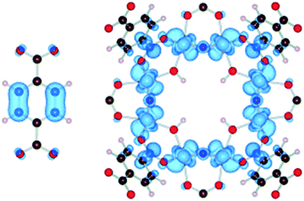 | ||
| Fig. 2 Highest occupied states (HOCO) are localized on the aromatic organic group, while the lowest unoccupied states (LUCO) are localized on the octameric TiO2 units for NH2-MIL-125(Ti).61 Reproduced with permission from Wiley. | ||
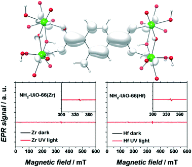 | ||
| Fig. 3 EPR spectra of dark (black) and UV-illuminated (red) NH2-UiO-66(Zr) (left) and NH2-UiO-66(Hf) (right). The photoexcited electron is primarily centred on the organic linker. Adapted with permission from Nasalevich et al.59 | ||
Remarkably, electron paramagnetic resonance (EPR) and DFT calculations were crucial to determine the electronic origins of photocatalytic activity in NH2-UiO-66(Zr) and NH2-UiO-66(Hf). On the one hand, the detection of paramagnetic Zr+3/Hf+3 should be straightforward, being a key experimental proof for LMCT. On the other hand, DFT calculations can give insights into the composition, energy, and distribution of the frontier orbitals.53,56,59 It is noteworthy that concepts like matching electronic energy levels and orbital symmetry are still rarely applied in MOF chemistry; however, knowing the electronic structure of a material can provide very valuable guidelines for their design in photocatalysis.
Kinetics of the photoexcited state defined by the organic linker
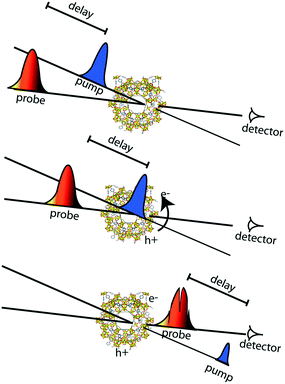
Apart from the thermodynamic requirement that implies that LUCO and HOCO positions need to be appropriate in order to run the desired redox half reaction, as mentioned briefly above, the kinetics of the photoexcited states critically influence efficiency in photocatalysis. Accordingly, the lifetime of the charge separated state(s) is of paramount importance, since it needs to be sufficiently long, such that catalytic conversion can compete with the charge separated state decay. These kinetic considerations are often not explicitly considered in examples of photocatalytic MOFs in the literature. Thus, it is highly recommended to profit from the advanced spectroscopic techniques that are nowadays available for the understanding of the photocatalytic reaction mechanisms and for a better design of MOF photocatalytic systems.In this context, time-resolved absorption spectroscopy (TAS) is a widely employed technique in photocatalysis to study the formation, decay, recombination, and transfer processes of photogenerated charge carriers.68 In this technique samples are excited by a laser pulse, and the absorption of the photogenerated intermediates is detected by time-resolved optical spectroscopy, usually in the UV/VIS/NIR region, employing white light for the analysis (Fig. 4).
The type of dynamics that one wants to follow determines the required temporal resolution of the laser system. For dynamic processes from nanosecond to millisecond time scales, the most common tool is laser flash photolysis, where a sample is first excited by an intense pulse laser, populating the excited state. This change is spectroscopically monitored by applying a synchronized probe light (i.e. intense flash xenon lamp) by measuring the transmittance for transparent samples or the reflectance for opaque samples, respectively, before and after the laser excitation.69
However, when the efficiency of the photoexcitation process is limited by the fast decay (within a few picoseconds) of the photogenerated charges, the fact that the remaining charges have a microsecond lifetime makes no difference, and unravelling the dynamics at short time scales becomes crucial. Thus, in order to capture the entire extent of the photoexcited state decays and the fast dynamics of photocatalytic systems, subpicosecond time resolution is needed. Ultrafast pump-probe spectroscopy allows us to get direct information on the MOFs' excited redox-active states and to study their decay profiles from subpicoseconds up to several nanoseconds time scales.70
In the case of very weak absorbance but reasonable fluorescence, this is usually done in an emission fashion.71,72
Here, time-correlated single-photon counting (TCSPC) is the most popular method, measuring picosecond emission decays. For the case of femtosecond emission transients, the fluorescence up-conversion technique is often used.73,74
Regarding ultrafast measurements in absorbance mode, the ultrafast study done on the MIL-125(Ti) series is one of the clearest examples.52 Here, MOF suspensions were excited at their wavelength absorption maxima. By separating the large MOF particles (>100 nm) from the suspension, the experiments could be done in transmittance fashion, avoiding light scattering and following the decay kinetics with a picosecond time resolution. In this way, the kinetics of the photoexcitation process were elucidated for two titanium MOFs, MIL-125(Ti) and NH2-MIL-125(Ti). Even though both MOFs undergo a ligand-to-metal charge transfer transition, it was found that NH2-MIL-125(Ti) has a remarkably longer lifetime due to the electron-donating primary amine on the benzene ring. Analogous comprehensive studies should be included more often in reported photocatalytic systems in order to enable the creation of more design guidelines for photocatalytic MOFs.
Localization of the photogenerated electrons and holes
In addition to the charge recombination rates, the localization of photogenerated electrons and holes is critical for the design of reduction and oxidation catalysts, respectively. Indeed, these charges need to be able to be easily transferred to reactants in order to achieve catalytic conversion. The most unambiguous way to assess this issue experimentally in MOF photocatalytic systems is by spectroelectrochemistry (SEC). In general, this technique consists of recording the in situ absorption spectra upon electrochemical oxidation/reduction of a material, allowing for the detection of unknown intermediates or products created by the redox reaction.75 However, its potential on the localization of charge carriers resides in the direct comparison of the MOF SEC spectrum with that of its building units. Moreover, and despite the different time resolution of both techniques, this also allows for a better understanding of the TA spectra obtained by ultrafast spectroscopy.Typically, SEC experiments (Fig. 5) are performed on transparent thin glass tubes or flat cells with incorporated electrodes (i.e. working electrode, counter electrode and, frequently, reference electrode).75 In order to observe the changes in the analyte, optical cells are usually made from conducting transparent materials (i.e. ITO) or on somewhat transparent noble metal grids.
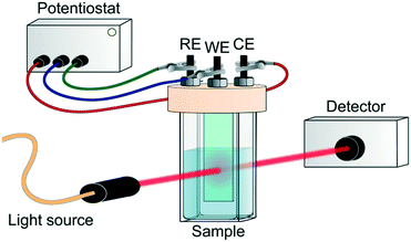 | ||
| Fig. 5 Scheme of SEC experiment. RE, WE and CE refer to reference, working and counter electrode, respectively. | ||
Despite the fact that SEC can potentially assist in unravelling the photoexcitation process, these measurements on photocatalytic MOFs are not straightforward and often not possible to carry out due to, once again, the MOF's insulating character. Moreover, a compromise in concentration is necessary when cyclic voltammetry is linked to SEC results for MOFs. Often, higher MOF concentrations are required than commonly used in electrochemical measurements for a sufficient spectroscopic response. This toughens the electrochemical part of the measurement due to the increased probability of the MOF falling from the electrode where it is deposited.
Going back to the earlier discussed titanium-MOF example, SEC could be performed only on the soluble models of the organic and inorganic NH2-MIL-125(Ti) constituents. SEC analysis gave strong evidence for the LMCT character of the NH2-MIL-125(Ti) photoexcited state through the detection of the absorption fingerprints of the linker radical cation and the reduced Ti-oxocluster.
A more elaborate way to precisely localize the photoexcited charges is by employing VIS-pump mid-IR-probe spectroscopy. By using this ultrafast technique, electrons and holes can be traced through the different organic groups of the framework. For instance, mid-IR transient spectra were measured in the NH2-MIL-125(Ti) material by placing a very thin layer of concentrated MOF suspension in a mid-IR transparent solvent on a cell made from CaF2 windows. These measurements revealed that the photogenerated hole resides on the amino group in NH2-MIL-125(Ti) (Fig. 6).
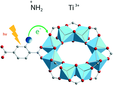 | ||
| Fig. 6 Ligand-to-metal charge transfer (LMCT) and location of photogenerated charges in NH2-MIL-125(Ti).52 Reproduced with permission from Wiley. | ||
State-of-the-art spectroscopy is not limited to the aforementioned techniques. VIS-pump X-ray-probe spectroscopy allows recording of X-ray absorption spectra for X-ray diffraction with a time resolution of hundreds of femtoseconds at free electron laser facilities, and for EXAFS spectra achieving tens of microseconds time resolution at synchrotron facilities. This powerful technique can be used to unravel the mechanisms behind photocatalytic reactions, especially when dealing with multicomponent arrangements.76 It has not yet been applied in any photocatalytic MOF; nonetheless, future studies using these tools will definitely allow for a better understanding of the field.
Moreover, charge transfer is another crucial piece of the artificial photosynthetic scheme. Once more, by using ultrafast spectroscopic techniques, charge transfer from photoexcited MOFs to occluded molecules (i.e. reactants) can be studied.
Strategies for photocatalysis by guest inclusion
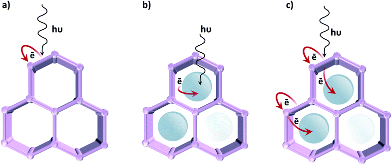
In contrast to classical semiconductor materials, where tuneability is commonly limited to the modification of surfaces by noble metal nanoparticles or, occasionally, transition metal complexes, in the case of MOFs different approaches can be followed in order to induce photocatalytic activity (Fig. 7). The first one, described in the previous section, uses the organic linker as an antenna for light sensitizing and charge transfer to the inorganic cluster by exploiting ligand-to-metal charge transfer (LMCT). We have earlier emphasized that photocatalytic MOFs that feature LMCT are ideal due to the efficient charge separation. Moreover, by tuning the organic linker (introducing additional substituents, using mixed linkers19 or even capping additional metal ions), the oxidative power of these MOFs can be affected. The same analogy can be extended towards reductions: since metal orbitals in such MOFs define the position of the LUCO, the reductive power can be altered by choosing metal ions that possess appropriate orbitals. Alternatively, the optical response can be modified by tuning the cluster-forming metal or even by using mixed metal clusters. The latter has been used as an approach to create mid-gap metal-centred states that result in the MOF featuring a LMCT transition, clusters that cannot be formed via direct synthesis. For instance, it has been proposed that in the UiO-66 framework Ti4+ could substitute for Zr4+ in the oxocluster. However, it remains unclear whether the metals truly exchange or are just anchored to the node.Even if such manipulations on their electronic properties lead to improvements in the MOFs' photocatalytic performance, so far the activity of reported MOFs for artificial photosynthesis is very modest. Since tuning the optical absorption does not appear to be the issue, active site engineering is certainly the path to follow in order to improve their catalytic activity.
Accordingly, a second strategy is to employ MOFs as a passive container for the encapsulation of a light absorbing photocatalyst.30,31 These active species are often homogeneous catalysts based on precious metals, and by encapsulating29 or covalently bonding them to the framework, leaching has been successfully prevented.22 This strategy was also employed on a UiO-66 framework, using Ru(bpy)3 as a photosensitizer. Inspired by nature, the authors selected an organometallic Fe2 complex for hydrogen evolution.24 Fortunately, MOFs are not solely limited to being a static scaffold, thus promoting synergistic and cooperative interactions among the MOF and the encapsulated catalyst is a more stimulating third approach, where charge transfer between MOF and guest is achieved.29 This method was applied, for example, on a UiO-67 framework consisting of biphenyl-4,4′-dicarboxylic acid combined with Ir-based ligands. When loaded with Pt nanoparticles,19 it showed remarkable activity for hydrogen evolution due to the efficient electron transfer from the Ir-complex to Pt. Despite its good stability under photocatalytic conditions, this example relies on noble metals, limiting the applicability. Thus, new prospects for enhancing the MOF's photocatalytic performances appear by using redox- and photoactive and inexpensive metals, such as Fe and Co.
In line with this, the “ship-in-a-bottle” technique for assembling a cobalt-based electrocatalyst in the NH2-MIL-125(Ti) framework was reported. Although the precise structure of the catalyst remains unknown, the achieved performance for visible light hydrogen evolution was outstanding.29 This work revealed the potential of modular design in photocatalytic MOFs and the importance of cooperativity between the MOF's photoactive matrix and a catalytically active encapsulated guest. This work encouraged other researchers to use different ligands in a surprisingly similar manner.77
Outlook
MOFs provide an attractive matrix to achieve solar energy conversion by hierarchically organizing light-harvesting antennae and catalytic centres. Nonetheless so far, photocatalytic MOFs also show several drawbacks. Indeed, it is fair to admit that, despite some advances in the field during the past years, photocatalytic MOF performance is still far from the state-of-the-art.It is noteworthy that while most reports focus on the hydrogen evolution or CO2 reduction reaction, there are only a few examples of MOFs in water oxidation. This is not surprising, since most MOFs are built up from carboxylate linkers and typically do not possess enough oxidation power to perform water oxidation. Moreover, the use of buffer solutions and strong oxidants typically used for water oxidation results in extreme environments where MOFs are unstable. Consequently, every study focusses on hydrogen evolution by means of a sacrificial electron donor (usually triethanolamine or trimethylamine) to provide an oxidative half reaction to close the catalytic cycle. It is vital to understand the role of these sacrificial electron donors78 such that we can replace them by recyclable electron donors.79,80 Then, by combining this system with a water oxidation catalyst, sustainable solar fuel generation can be achieved.27
Low charge mobility is another limitation in most photocatalytic MOFs.37 Fortunately, the MOF's porous nature can compensate for it and allows for the diffusion of reactants and redox carriers throughout the crystallite. In addition, limitations by light penetration and light scattering should also be considered in MOF photocatalytic systems. Accordingly, and combining the former with the lack of photogenerated charge mobility, different reaction rates can be obtained at the external surface and in the bulk of the MOF photocatalyst.81
Thus, conducting properties are very attractive for improved efficiency, potentially allowing for higher electron/hole separation and for physical separation of charges (in photo-electrochemical cells, PECs). Despite the fact that an exciting new field on conductor MOFs has emerged,39,48 insights into the electronic transport properties of MOFs are still lacking. Moreover, we would like to encourage the application of conductive MOFs in photocatalysis for solar fuel generation.
We have emphasized that a strong visible light absorption, a long lifetime of excited states and a high yield of charge separated states are the main requirements for an excellent photocatalyst. Accordingly, matching reactant conversion times with the lifetime of photogenerated charges is the key for minimizing charge recombination and maximizing the energy utilized for the photochemical reaction. We believe that the combination of innovative spectroscopic techniques and the appropriate photocatalytic testing82 will advance this field greatly.
Even when achieving a high quantum yield is the ultimate goal, the future growth of MOF-based photocatalysts requires deeper understanding of the operation of current systems and their advantages over other photocatalytic materials. The different ultrafast spectroscopic methods that have been outlined in this highlight are highly powerful tools to unravel MOF functioning and to develop design guidelines for these materials in photocatalysis.
Acknowledgements
Dr. Alla Dikhtiarenko is gratefully acknowledged for her assistance in making Fig. 7.References
- W. Ostwald, Die Mühle des Lebens, Leipzig, 1911 Search PubMed.
- A. Fujishima and K. Honda, Nature, 1972, 238, 37–38 CrossRef CAS PubMed.
- Z. Jiang, Y. Tang, Q. Tay, Y. Zhang, O. I. Malyi, D. Wang, J. Deng, Y. Lai, H. Zhou, X. Chen, Z. Dong and Z. Chen, Adv. Energy Mater., 2013, 3, 1368–1380 CrossRef CAS.
- A. Corma and H. Garcia, Chem. Commun., 2004, 1443–1459 RSC.
- T. Hisatomi, J. Kubota and K. Domen, Chem. Soc. Rev., 2014, 43, 7520–7535 RSC.
- X. Li, J. Yu and M. Jaroniec, Chem. Soc. Rev., 2016, 45, 2603–2636 RSC.
- H. Furukawa, K. E. Cordova, M. O'Keeffe and O. M. Yaghi, Science, 2013, 341 Search PubMed.
- H.-C. Zhou, J. R. Long and O. M. Yaghi, Chem. Rev., 2012, 112, 673–674 CrossRef CAS PubMed.
- M. P. Suh, H. J. Park, T. K. Prasad and D.-W. Lim, Chem. Rev., 2012, 112, 782–835 CrossRef CAS PubMed.
- J.-R. Li, J. Sculley and H.-C. Zhou, Chem. Rev., 2012, 112, 869–932 CrossRef CAS PubMed.
- S. Bordiga, C. Lamberti, G. Ricchiardi, L. Regli, F. Bonino, A. Damin, K. P. Lillerud, M. Bjorgen and A. Zecchina, Chem. Commun., 2004, 2300–2301 RSC.
- M. Alvaro, E. Carbonell, B. Ferrer, F. X. Llabrés i Xamena and H. Garcia, Chem. – Eur. J., 2007, 13, 5106–5112 CrossRef CAS PubMed.
- F. X. Llabrés i Xamena, A. Corma and H. Garcia, J. Phys. Chem. C, 2007, 111, 80–85 Search PubMed.
- J. Gascon, M. D. Hernández-Alonso, A. R. Almeida, G. P. M. van Klink, F. Kapteijn and G. Mul, ChemSusChem, 2008, 1, 981–983 CrossRef CAS PubMed.
- Y. Kataoka, K. Sato, Y. Miyazaki, K. Masuda, H. Tanaka, S. Naito and W. Mori, Energy Environ. Sci., 2009, 2, 397–400 CAS.
- Y. Horiuchi, T. Toyao, M. Saito, K. Mochizuki, M. Iwata, H. Higashimura, M. Anpo and M. Matsuoka, J. Phys. Chem. C, 2012, 116, 20848–20853 CAS.
- T. Toyao, M. Saito, S. Dohshi, K. Mochizuki, M. Iwata, H. Higashimura, Y. Horiuchi and M. Matsuoka, Chem. Commun., 2014, 50, 6779–6781 RSC.
- D. Sun, L. Ye and Z. Li, Appl. Catal., B, 2015, 164, 428–432 CrossRef CAS.
- C. Wang, K. E. deKrafft and W. Lin, J. Am. Chem. Soc., 2012, 134, 7211–7214 CrossRef CAS PubMed.
- H.-Q. Xu, J. Hu, D. Wang, Z. Li, Q. Zhang, Y. Luo, S.-H. Yu and H.-L. Jiang, J. Am. Chem. Soc., 2015, 137, 13440–13443 CrossRef CAS PubMed.
- T. Toyao, M. Saito, S. Dohshi, K. Mochizuki, M. Iwata, H. Higashimura, Y. Horiuchi and M. Matsuoka, Res. Chem. Intermed., 2016, 42, 7679–7688 CrossRef CAS.
- C. Wang, Z. Xie, K. E. de Krafft and W. Lin, J. Am. Chem. Soc., 2011, 133, 13445–13454 CrossRef CAS PubMed.
- H. Zhang, J. Wei, J. Dong, G. Liu, L. Shi, P. An, G. Zhao, J. Kong, X. Wang, X. Meng, J. Zhang and J. Ye, Angew. Chem., Int. Ed., 2016, 55, 14310–14314 CrossRef CAS PubMed.
- S. Pullen, H. Fei, A. Orthaber, S. M. Cohen and S. Ott, J. Am. Chem. Soc., 2013, 135, 16997–17003 CrossRef CAS PubMed.
- D. Wang, R. Huang, W. Liu, D. Sun and Z. Li, ACS Catal., 2014, 4, 4254–4260 CrossRef CAS.
- D. Wang, M. Wang and Z. Li, ACS Catal., 2015, 5, 6852–6857 CrossRef CAS.
- Y. Fu, D. Sun, Y. Chen, R. Huang, Z. Ding, X. Fu and Z. Li, Angew. Chem., Int. Ed., 2012, 51, 3364–3367 CrossRef CAS PubMed.
- D. Sun, Y. Fu, W. Liu, L. Ye, D. Wang, L. Yang, X. Fu and Z. Li, Chem. – Eur. J., 2013, 19, 14279–14285 CrossRef CAS PubMed.
- M. A. Nasalevich, R. Becker, E. V. Ramos-Fernandez, S. Castellanos, S. L. Veber, M. V. Fedin, F. Kapteijn, J. N. H. Reek, J. I. van der Vlugt and J. Gascon, Energy Environ. Sci., 2015, 8, 364–375 CAS.
- J. He, Z. Yan, J. Wang, J. Xie, L. Jiang, Y. Shi, F. Yuan, F. Yu and Y. Sun, Chem. Commun., 2013, 49, 6761–6763 RSC.
- J.-L. Wang, C. Wang and W. Lin, ACS Catal., 2012, 2, 2630–2640 CrossRef CAS.
- T. Zhang and W. Lin, Chem. Soc. Rev., 2014, 43, 5982–5993 RSC.
- A. Dhakshinamoorthy, A. M. Asiri and H. García, Angew. Chem., Int. Ed., 2016, 55, 5414–5445 CrossRef CAS PubMed.
- S. Wang and X. Wang, Small, 2015, 11, 3097–3112 CrossRef CAS PubMed.
- L. Zeng, X. Guo, C. He and C. Duan, ACS Catal., 2016, 6, 7935–7947 CrossRef CAS.
- Y. Horiuchi, T. Toyao, M. Takeuchi, M. Matsuoka and M. Anpo, Phys. Chem. Chem. Phys., 2013, 15, 13243–13253 RSC.
- M. A. Nasalevich, M. van der Veen, F. Kapteijn and J. Gascon, CrystEngComm, 2014, 16, 4919–4926 RSC.
- M. A. Nasalevich, M. G. Goesten, T. J. Savenije, F. Kapteijn and J. Gascon, Chem. Commun., 2013, 49, 10575–10577 RSC.
- L. Sun, M. G. Campbell and M. Dincă, Angew. Chem., Int. Ed., 2016, 55, 3566–3579 CrossRef CAS PubMed.
- C. H. Hendon, D. Tiana, M. Fontecave, C. Sanchez, L. D'Arras, C. Sassoye, L. Rozes, C. Mellot-Draznieks and A. Walsh, J. Am. Chem. Soc., 2013, 135, 10942–10945 CrossRef CAS PubMed.
- K. Hendrickx, D. E. P. Vanpoucke, K. Leus, K. Lejaeghere, A. Van Yperen-De Deyne, V. Van Speybroeck, P. Van Der Voort and K. Hemelsoet, Inorg. Chem., 2015, 54, 10701–10710 CrossRef CAS PubMed.
- B. Civalleri, F. Napoli, Y. Noel, C. Roetti and R. Dovesi, CrystEngComm, 2006, 8, 364–371 RSC.
- P. M. Wojciechowski, W. Zierkiewicz, D. Michalska and P. Hobza, J. Chem. Phys., 2003, 118, 10900–10911 CrossRef CAS.
- J. H. Cavka, S. Jakobsen, U. Olsbye, N. Guillou, C. Lamberti, S. Bordiga and K. P. Lillerud, J. Am. Chem. Soc., 2008, 130, 13850–13851 CrossRef PubMed.
- M. G. Goesten, F. Kapteijn and J. Gascon, CrystEngComm, 2013, 15, 9249–9257 RSC.
- M. A. Nasalevich, M. G. Goesten, T. J. Savenije, F. Kapteijn and J. Gascon, Chem. Commun., 2015, 51, 961–962 RSC.
- S. M. Chavan, G. C. Shearer, S. Svelle, U. Olsbye, F. Bonino, J. Ethiraj, K. P. Lillerud and S. Bordiga, Inorg. Chem., 2014, 53, 9509–9515 CrossRef CAS PubMed.
- I. Hod, P. Deria, W. Bury, J. E. Mondloch, C.-W. Kung, M. So, M. D. Sampson, A. W. Peters, C. P. Kubiak, O. K. Farha and J. T. Hupp, Nat. Commun., 2015, 6, 8304 CrossRef CAS PubMed.
- A. Morozan and F. Jaouen, Energy Environ. Sci., 2012, 5, 9269–9290 CAS.
- N. Kornienko, Y. Zhao, C. S. Kley, C. Zhu, D. Kim, S. Lin, C. J. Chang, O. M. Yaghi and P. Yang, J. Am. Chem. Soc., 2015, 137, 14129–14135 CrossRef CAS PubMed.
- A. J. Bard and L. R. Faulkner, in Electrochemical Methods: Fundamentals and Applications, Wiley, New York, 2001 Search PubMed.
- J. G. Santaclara, M. A. Nasalevich, S. Castellanos, W. H. Evers, F. C. M. Spoor, K. Rock, L. D. A. Siebbeles, F. Kapteijn, F. Grozema, A. Houtepen, J. Gascon, J. Hunger and M. A. van der Veen, ChemSusChem, 2016, 9, 388–395 CrossRef CAS PubMed.
- K. T. Butler, C. H. Hendon and A. Walsh, J. Am. Chem. Soc., 2014, 136, 2703–2706 CrossRef CAS PubMed.
- K. T. Butler, C. H. Hendon and A. Walsh, ACS Appl. Mater. Interfaces, 2014, 6, 22044–22050 CAS.
- A. Walsh, K. T. Butler and C. H. Hendon, MRS Bull., 2016, 41, 870–876 CrossRef.
- C. H. Hendon and A. Walsh, Chem. Sci., 2015, 6, 3674–3683 RSC.
- H.-J. Son, S. Jin, S. Patwardhan, S. J. Wezenberg, N. C. Jeong, M. So, C. E. Wilmer, A. A. Sarjeant, G. C. Schatz, R. Q. Snurr, O. K. Farha, G. P. Wiederrecht and J. T. Hupp, J. Am. Chem. Soc., 2013, 135, 862–869 CrossRef CAS PubMed.
- C. Zou, M.-H. Xie, G.-Q. Kong and C.-D. Wu, CrystEngComm, 2012, 14, 4850–4856 RSC.
- M. A. Nasalevich, C. H. Hendon, J. G. Santaclara, K. Svane, B. van der Linden, S. L. Veber, M. V. Fedin, A. J. Houtepen, M. A. van der Veen, F. Kapteijn, A. Walsh and J. Gascon, Sci. Rep., 2016, 6, 23676 CrossRef CAS PubMed.
- M. de Miguel, F. Ragon, T. Devic, C. Serre, P. Horcajada and H. Garcia, ChemPhysChem, 2012, 13, 3651–3654 CrossRef CAS PubMed.
- A. Walsh and C. R. A. Catlow, ChemPhysChem, 2010, 11, 2341–2344 CrossRef CAS PubMed.
- J. Long, S. Wang, Z. Ding, S. Wang, Y. Zhou, L. Huang and X. Wang, Chem. Commun., 2012, 48, 11656–11658 RSC.
- D. Sun, W. Liu, M. Qiu, Y. Zhang and Z. Li, Chem. Commun., 2015, 51, 2056–2059 RSC.
- M. Gutierrez, F. Sanchez and A. Douhal, Phys. Chem. Chem. Phys., 2016, 18, 5112–5120 RSC.
- A. Fateeva, P. A. Chater, C. P. Ireland, A. A. Tahir, Y. Z. Khimyak, P. V. Wiper, J. R. Darwent and M. J. Rosseinsky, Angew. Chem., Int. Ed., 2012, 51, 7440–7444 CrossRef CAS PubMed.
- Y. Liu, Y. Yang, Q. Sun, Z. Wang, B. Huang, Y. Dai, X. Qin and X. Zhang, ACS Appl. Mater. Interfaces, 2013, 5, 7654–7658 CAS.
- M.-H. Xie, X.-L. Yang, C. Zou and C.-D. Wu, Inorg. Chem., 2011, 50, 5318–5320 CrossRef CAS PubMed.
- J. Schneider, M. Matsuoka, M. Takeuchi, J. Zhang, Y. Horiuchi, M. Anpo and D. W. Bahnemann, Chem. Rev., 2014, 114, 9919–9986 CrossRef CAS PubMed.
- J. Schneider, K. Nikitin, R. Dillert and D. W. Bahnemann, Faraday Discuss., 2017 10.1039/C6FD00193A , Advance Article.
- R. Berera, R. Grondelle and J. T. M. Kennis, Photosynth. Res., 2009, 101, 105–118 CrossRef CAS PubMed.
- M. Gutierrez, B. Cohen, F. Sanchez and A. Douhal, Phys. Chem. Chem. Phys., 2016, 18, 27761–27774 RSC.
- M. Gutiérrez, F. Sánchez and A. Douhal, Chem. – Eur. J., 2016, 22, 13072–13082 CrossRef PubMed.
- M. A. Ratner, Int. J. Quantum Chem., 1987, 31, 989 CrossRef.
- X.-X. Zhang, C. Würth, L. Zhao, U. Resch-Genger, N. P. Ernsting and M. Sajadi, Rev. Sci. Instrum., 2011, 82, 063108 CrossRef PubMed.
- W. Kaim and J. Fiedler, Chem. Soc. Rev., 2009, 38, 3373–3382 RSC.
- G. Smolentsev, A. Guda, X. Zhang, K. Haldrup, E. S. Andreiadis, M. Chavarot-Kerlidou, S. E. Canton, M. Nachtegaal, V. Artero and V. Sundstrom, J. Phys. Chem. C, 2013, 117, 17367–17375 CAS.
- Z. Li, J.-D. Xiao and H.-L. Jiang, ACS Catal., 2016, 6, 5359–5365 CrossRef CAS.
- T. Morimoto, T. Nakajima, S. Sawa, R. Nakanishi, D. Imori and O. Ishitani, J. Am. Chem. Soc., 2013, 135, 16825–16828 CrossRef CAS PubMed.
- B. C. M. Martindale, E. Joliat, C. Bachmann, R. Alberto and E. Reisner, Angew. Chem., Int. Ed., 2016, 55, 9402–9406 CrossRef CAS PubMed.
- R. D. Richardson, E. J. Holland and B. K. Carpenter, Nat. Chem., 2011, 3, 301–303 CrossRef CAS PubMed.
- M. Motegh, PhD Thesis, Delft University of Technology, 2013 Search PubMed.
- M. Qureshi and K. Takanabe, Chem. Mater., 2016, 9, 158–167 Search PubMed.
| This journal is © The Royal Society of Chemistry 2017 |

