Recent advances in magnetic nanoparticle-based multi-modal imaging
Tae-Hyun
Shin
,
Youngseon
Choi
,
Soojin
Kim
and
Jinwoo
Cheon
*
Department of Chemistry, Yonsei University, Seoul, 120-749, Korea. E-mail: jcheon@yonsei.ac.kr
First published on 5th February 2015
Abstract
Magnetic nanoparticles have been extensively explored as a versatile platform for magnetic resonance imaging (MRI) contrast agents due to their strong contrast enhancement effects together with the platform capability for multiple imaging modalities. In this tutorial review, we focus on recent progress in the use of magnetic nanoparticles for MRI contrast agents and multi-mode imaging agents such as T1–T2 MRI, MRI-optical, and MRI-radioisotopes. This review also highlights emerging magnetic imaging techniques such as magnetic particle imaging (MPI), magneto-motive ultrasound imaging (MMUS), and magneto-photoacoustic imaging (MPA).
Key learning points(1) Basic principles of MRI and key design parameters for nanoparticle-based MRI contrast agents.(2) Essentials of multi-modal imaging for enhanced sensitivity and accuracy of biomedical imaging. (3) Emerging magnetic imaging techniques: (i) MPI, (ii) MMUS, and (iii) MPA. |
1. Introduction
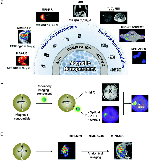
During the past few decades, scientific breakthroughs from physics, chemistry, engineering, and medicine have led to biomedical imaging techniques with high sensitivity and resolution, which aid in both the understanding of biological phenomena and the detection of diseases. Currently, the representative imaging modalities in either preclinical research or clinical settings are MRI, positron emission tomography (PET), computed tomography (CT), single-photon emission computed tomography (SPECT), optical fluorescence imaging, ultrasound (US) imaging, and photoacoustic (PA) imaging (Table 1).1 Owing to the need for accurate imaging of small biological targets in complex environments, new trials in performance enhancements of imaging techniques are in progress. One of the methods under study is the concept of multi-modality to complement the weakness of a single imaging modality with the strengths of other imaging modalities.2 Another strategy is the use of imaging agents to overcome inherent instrumental limitations, such as sensitivity or resolution of a particular imaging technique, and ultimately to enhance the accuracy of biomedical imaging.3 In particular, magnetic nanoparticles have been serving as a platform for MRI contrast agents due to their tunable properties such as magnetism, size, and facile conjugation with biologically functional units (Fig. 1a).4 For example, the magnetic parameters, such as saturation magnetization (ms) that proportionally affects the MRI contrast, can be optimized via fine control of the size or the composition of the nanoparticles. In addition, their surface functionalization provides them with the ability to carry a wide range of imaging moieties, such as fluorescent molecules and radioisotopes, which makes nanoparticles useful in multi-modal imaging systems. The versatility of magnetic nanoparticles has indeed allowed them to become an important platform for multi-modal imaging applications, such as MRI-optical and MRI–PET/SPECT, which combines the advantages of each imaging modality to achieve highly accurate images (Fig. 1b).3 Recently, magnetic nanoparticles have also been demonstrated for their utility in non-traditional multi-modal imaging techniques, such as MPI, MMUS, and MPA that employ magnetic nanoparticles as a source of the imaging signals (Fig. 1c).| Imaging techniques | Signal measured | Spatial resolution | Sensitivitya | Penetration deptha | Preclinical use | Clinical use |
|---|---|---|---|---|---|---|
| MRI, magnetic resonance imaging; PET, positron emission tomography; SPECT, single-photon emission computed tomography; FLI, fluorescence imaging; BLI, bioluminescence imaging; MPI, magnetic particle imaging; US, ultrasound; PA, photoacoustic.a Strength and weakness are given using a relative scale (+, poor; ++, good; +++, excellent). | ||||||
| MRI | Radio frequency waves | +++ | + | +++ | Yes | Yes |
| PET | γ-rays | + | +++ | +++ | Yes | Yes |
| SPECT | γ-rays | + | ++ | +++ | Yes | Yes |
| Optical (FLI or BLI) | Visible to infrared light | + | ++ | + | Yes | No |
| MPI | Radio frequency waves | + | ++ | +++ | Yes | No |
| US imaging | High frequency sound waves | ++ | + | + | Yes | Yes |
| PA imaging | High frequency sound waves | ++ | ++ | + | Yes | No |
Magnetic nanoparticle-based multi-modal imaging can be categorized into two different approaches (Fig. 1b and c). One utilizes magnetic nanoparticles conjugated with secondary imaging components. These nanoparticles are designed to induce adequate signals in multiple imaging modalities, which can have the desired high spatial resolution (e.g. MRI) and sensitivity (e.g. optical, PET, or SPECT). When these signals are combined in a complementary manner, the biological targets can be imaged with high accuracy. The other approach uses the inherent magnetic properties of magnetic nanoparticles as a source of multi-modal imaging signals without additional imaging moieties. With the advance of several new imaging techniques (e.g. MPI, MMUS, and MPA), which can directly visualize nanoparticles, the location of the magnetic nanoparticles can be determined.5–7 These magnetic nanoparticle-based imaging techniques can be combined with conventional imaging techniques (e.g. MRI and US). The overlay of images from respective modalities provides accurate information on the distribution of the magnetic nanoparticles without the interference of background signals, which could ultimately lead to a higher diagnostic accuracy of diseases. These magnetic nanoparticle-based multi-modal imaging approaches are being actively pursued to improve the accuracy of cancer diagnosis, cardiovascular disease imaging, and cell tracking in regenerative medicine.
In this review, we discuss how magnetic nanoparticles can be designed to enhance the sensitivity of MRI and synergistically integrated with other imaging modalities to achieve high accuracy. To better explain the MRI contrast effects of magnetic nanoparticles, we first discuss the basic principles of MRI and the effects of various nanoscale parameters on MRI contrast enhancements. Then, the development of nanoparticle multi-modal imaging techniques such as T1–T2 MRI, MRI-optical, and MRI–PET/SPECT dual-modal imaging will be discussed. Finally, we highlight recent demonstrations of magnetic nanoparticles as imaging agents for newly emerging multi-modal imaging techniques such as MPI, MMUS, and MPA.
2. Magnetic nanoparticles for MR imaging
Among a number of clinically available imaging techniques, MRI is considered one of the foremost diagnostic imaging tools because of its unique features, including high spatial resolution, strong soft tissue contrast, and no radiation risk.8 Nonetheless, the inherently poor sensitivity of MRI remains a limitation for the accurate detection of small biological targets, such as tumors in early stage cancer or subtle anatomical changes. To address this sensitivity issue, magnetic nanoparticles have been used as MRI contrast agents. In this section, we discuss the basic principles of MRI and the development of nanoparticle-based MRI contrast agents.2.1. Basic principles of MRI
Similar to nuclear magnetic resonance (NMR), MRI can utilize either 1H, 11B, 13C, 19F, or 31P as a source of signal. Among these, water protons (1H) are the most common source in the current clinical MRI technique.8 Under an external magnetic field (B0), proton nuclear spins are aligned parallel with the direction of B0, which induces longitudinal magnetization. At the same time, the proton nuclear spins precess with a Larmor frequency of ω0 = γB0 (γ is gyromagnetic constant). When radiofrequency (RF) pulses of ω0 are applied, the proton nuclear spins are resonantly excited and aligned antiparallel with B0, which generates transverse magnetization while decreasing the longitudinal magnetization. Upon removal of the RF pulse, the excited water protons relax to the ground state (i.e. align parallel with B0) by emitting the energy gained from the RF pulse. This relaxation proceeds via two different processes: (i) T1 longitudinal relaxation, which results in longitudinal magnetization recovery and (ii) T2 transverse relaxation, which involves transverse magnetization decay originating from the loss of phase coherence and dephasing between the proton nuclear spins. MRI makes a record of these relaxation processes and then reconstructs them into gray scale images. MRI images can generally be categorized into two different imaging modes of T1-weighted images and T2-weighted images. For T1-weighted MRI images, a faster T1 relaxation rate (R1, the inverse of T1, s−1) gives a brighter contrast, and for T2-weighted MRI images, a faster T2 relaxation rate (R2, the inverse of T2, s−1) yields a darker contrast.Typically, the different water proton densities and tumbling rates, which are some of the factors that affect the rate of water proton relaxation, cause various biological tissues and organs to show characteristically distinct MRI contrasts. However, when the contrast difference between the target tissue (e.g. pathological lesions) and the surroundings (e.g. normal tissues) is marginal, it is difficult to accurately detect the target region of interest (ROI). Thus, MRI contrast agents that can accelerate the T1 or T2 relaxation rate in the ROI are used to increase the contrast between the pathological lesions and the normal tissues.
2.2. Magnetic nanoparticles as MRI contrast agents
MRI contrast agents are classified into T2 or T1 MRI contrast agents, depending on their relaxivity coefficients (r2 or r1, mM−1 s−1), which are the terms that define the ability to accelerate relaxation rates (R2 or R1, s−1).4 To be an effective T2 MRI contrast agent, a high r2 value is a prerequisite. In comparison, T1 MRI contrast agents need to have a high r1 and a low r2/r1 ratio. Magnetic nanoparticles can serve as effective T2 or T1 MRI contrast agents because the facile tuning of the nanoparticle magnetism permits them to have optimized r2, r1 values and r2/r1 ratios.For strong T2 contrast effects, it is desirable for nanoparticles to have large magnetization values. Under an external magnetic field, magnetic nanoparticles are magnetized, and they subsequently generate induced magnetic fields, which cause local magnetic perturbations. Because the precession frequency (ω0) of the water proton is determined by the strength of the external magnetic field, this inhomogeneity of the magnetic field causes proton nuclear spins to precess at different frequencies. Consequently, the dephasing process of the proton nuclear spins is accelerated with a faster T2 relaxation process. According to outer-sphere spin–spin relaxation approximation, the relationship between the magnetization and the T2 relaxation rate (R2) is described by eqn (1)
 | (1) |
In contrast, T1 contrast effects arise from the magnetically disordered spin layers at the surfaces of the magnetic nanoparticles. The metal ions at the nanoparticle surface have various numbers of unpaired electrons (e.g. 5 unpaired electrons for Fe3+) that effectively accelerate the T1 relaxation process.10 However, high magnetization of magnetic nanoparticles with high r2 and r2/r1 values is not suitable for T1 contrast agents. Therefore, increasing the portion of canted surface spins of nanoparticles by decreasing the size of the nanoparticles is devised to produce a large r1 while decreasing r2 and r2/r1 values. Theoretical investigations indicate that strong T1 contrast effects can be achieved when the sizes of the magnetic nanoparticles are smaller than 10 nm.11
2.3. Effects of magnetic nanoparticles on the MRI signal
The saturation magnetization (ms) of nanoparticles proportionally increases with the size of the magnetic nanoparticles (Fig. 2a and b), as described in eqn (2)
| ms = Ms[(r − d)/r]3 | (2) |
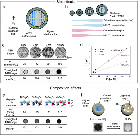 | ||
| Fig. 2 Effects of the magnetic nanoparticles on MRI contrast enhancements. (a) Magnetic spins (aligned interior spins and canted surface spins) of nanoparticle under an external magnetic field (B0). (b) Magnetic nanoparticle size vs. ms, T2 contrast effects, canted surface spins, and T1 contrast effects. (c and d) The effects of the size on T2 and T1 contrast enhancements. (c) As the size of the nanoparticles increases from 4 nm to 12 nm, ms and r2 increase to 102 emu g−1 and 218 mM−1 s−1, respectively. (d) The T1 contrast effects (r1) of extremely small size 3 nm iron oxide nanoparticles are ca. 2-fold higher than the 12 nm nanoparticles. (e and f) The effects of the composition on the T2 and T1 contrast enhancements. (e) Replacement of octahedral Fe2+ in ferrite nanoparticles with Mn2+ (MnFe2O4) results in ca. 1.5-fold increase in the r2 value over Fe3O4. (f) The embedding of Gd species in iron oxide nanoparticles makes disruption of the interior spins into dispersed spin states with the resulting outcome of the enhanced T1 contrast effects. (c) Reprinted with permission from ref. 13. Copyright 2005 American Chemical Society. (d) Reprinted with permission from ref. 10. Copyright 2011 American Chemical Society. (e) Reprinted with permission from Macmillan Publishers Ltd: ref. 20, copyright 2007. (f) Reprinted with permission from ref. 22. Copyright 2013 American Chemical Society. | ||
Recently, there have been several reports to further increase the T2 contrast effects by controlled clustering of magnetic nanoparticles to fit in the SDR.15 The aggregates of magnetic nanoparticles can increase ms and, thus, achieve a higher R2. One of the methods for controlled nanocluster is encapsulating multiple magnetic nanoparticles in amphiphilic block-copolymer micelles.15 For example, nanoclusters with a hydrodynamic size of 163 nm are prepared by enwrapping 7.4 nm iron oxide nanoparticles with poly(ethylene oxide-co-lactide) micelles. They show an r2 of 229 mM−1 s−1, which surpasses that of Feridex®. Alternatively, a template material, such as silica, has been tested to synthesize nanoclusters.16 Typically, the r2 value of the iron oxide nanoparticle cluster formed on the silica nanoparticle surface is higher than that of single iron oxide nanoparticles.
Such T2 relaxivity changes induced by the clustering of the magnetic nanoparticles can be utilized to detect a wide range of biomarkers.17,18 Termed as a magnetic relaxation switch (MRS), magnetic nanoparticles are modified with adequate functional molecules that can undergo assembly or disassembly in response to the presence of targets such as DNA, proteins, enzymes, and small molecules. Because most of the biomolecules are intrinsically low in magnetic susceptibility, an MRS can achieve high sensitivity with little interference from biological background.
T 1 contrast effects can be enhanced via reduction of the sizes of the nanoparticles (Fig. 2b), which is explained by the fact that the magnetically disordered spin layers on the nanoparticle surfaces make dominant contrast effects of the magnetic nanoparticles. The thickness of the spin canted surface layer is known to be 0.5–0.9 nm for iron oxide nanoparticles.10 These size effects on the T1 contrast enhancement have been investigated using extremely small iron oxide nanoparticles (ESIONs) with diameters of 2.2, 3, and 12 nm.10 In the case of the 3 nm ESIONs, 93.6% of the spins are canted with a relatively high r1 of 4.77 mM−1 s−1 (r2/r1 = 6.12), whereas 12 nm ESIONs with 38.6% of the canted spins show an r1 of 2.37 mM−1 s−1 (r2/r1 = 24.5) (Fig. 2d). The 3 nm ESIONs enhance the T1 signal high enough to visualize MCF-7 cancer cells in vitro. Furthermore, the ESIONs provide sufficient sensitivity to obtain MRI images of small diameter (0.2 mm) blood vessels, demonstrating their potential for blood pool MR angiography. More recently, 5.5 nm iron oxide nanoparticles with a high r1 value of 9.5 mM−1 s−1 and a low r2/r1 value of 2.97 are reported, where such strong T1 contrast effects result from the small nanoparticle size facilitating diffusion of water molecules by the hydrophilic and compact PEG surface coating.19
Similarly, this doping strategy is utilized to enhance T1 contrast effects by doping rare-earth metals into ferrite nanoparticles. Gadolinium-embedded iron oxide (GdIO) nanoparticles are designed to disrupt the spin ordering of iron oxide (Fe3O4) (Fig. 2f).22 Because Gd dopants influence the spin orientation of nanoparticles, not only the surface spins are canted but also the interior spins are magnetically disordered, which results in a low r2/r1 value. Thus, GdIO magnetic nanoparticles with a small size of 5 nm show higher T1 contrast effects (r1 = 7.85 mM−1 s−1 (Fe + Gd)) than iron oxide nanoparticles of the same size. GdIO exhibits a large T1 signal enhancement in the cardiovascular system (e.g. heart) when intravenously injected into a mouse.
Despite these successful MRI contrast enhancements by the composition control, concerns over the biocompatibility of metallic components have been reported. Although iron oxide nanoparticles are generally known to be biocompatible,23 other doping metals such as Gd have raised safety issues.24 For example, Gd ions liberated from nanoparticles upon organ uptake cause toxic side effects such as nephrogenic systemic fibrosis (NSF).24 One possible solution to minimize such issues is the fast excretion of nanoparticles via a renal clearance pathway, as demonstrated in the case of the 5 nm GdIO contrast agent.22
3. Magnetic nanoparticles for multi-modal imaging
In addition to the synthetic strategies such as size, composition, or shape control to improve MRI sensitivity, multi-modal imaging approaches have been examined to enhance both imaging sensitivity and accuracy. For example, imaging modalities such as PET can provide high sensitivity up to the femtomolar level of the biological targets of interest, while MRI can offer anatomical information with excellent resolution.2 Thus, combining MRI with PET or optical modalities not only delivers high resolution and sensitivity but also provides more detailed and accurate imaging information than using either modality alone. For such a synergistic integration of multi-modalities, magnetic nanoparticles have served as a platform for the direct addition of fluorescent molecules or radioisotopes. In the following sections, we showcase recent developments in magnetic nanoparticles for T1–T2 MRI, MRI-optical, and MRI–PET/SPECT dual-modal imaging to show the versatility of magnetic nanoparticles as multi-mode imaging agents.3.1. T 1–T2 dual-mode MRI contrast agents
Conventional nanoparticle MRI contrast agents typically serve as single-mode contrast agents, generating either bright (T1) or dark (T2) signal enhancement. Frequently, even with the use of contrast agents several issues still need to be addressed to achieve the desired image quality. One of the challenging issues is how to minimize the artifact signals in MRI images. MRI artifacts are either bright or dark signals, which frequently originate from endogenous factors such as fat, calcification, hemorrhages, blood clots, and air.23 These artifacts commonly found in disease lesions make it difficult to accurately identify the MRI signal coming from the contrast agents in the targets of interest.To overcome such ambiguities and accurately interpret the MRI images, T1–T2 dual-mode contrast agents have been introduced. These dual-mode contrast agents provide complementary T1-weighted and T2-weighted MRI images that enable self-confirmation of the signals from the contrast agents (Fig. 3a). These multi-mode MRI contrast agents are designed for a single instrument and have some advantages. For example, there are no discrepancies in the penetration depth between T1 and T2 images and no image mismatch issues which can occasionally occur when moving a sample between different imaging instruments. These characteristics of T1–T2 dual-mode contrast agents can be achieved by exploiting the unique design concepts of nanoparticles.
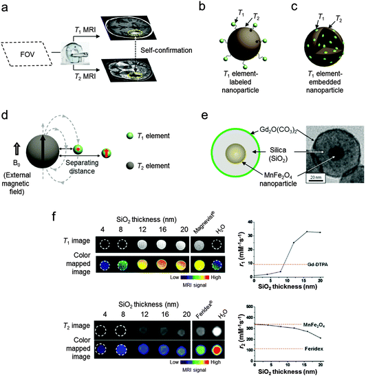 | ||
| Fig. 3 Basics of T1–T2 MRI dual-modal imaging. (a) Conceptual sketch of dual-modal MRI. Two images from T1 and T2 scans of a field-of-view (FOV) are obtained using an MRI instrument. The T1–T2 dual-mode contrast agents provide simultaneously bright (T1) and dark (T2) contrast effects in the respective scans. An overlay of the concurrently high T1 and T2 signals can help distinguish biological targets from the surroundings. (b and c) Schematic illustrations of the two types of conjugated T1–T2 dual-mode contrast agents. (d) Distance dependent magnetic coupling between T1 and T2 elements. The magnetic spins of the T1 element are perturbed by the T2 element-induced magnetic field when two elements are located in close proximity. (e) The magnetically decoupled core–shell type T1–T2 dual-mode contrast agents (DMCAs) and the corresponding TEM image. (f) T1 and T2 MRI images of T1–T2 DMCAs with different thicknesses of the separating SiO2 layer. Plots of r1 and r2vs. SiO2 thickness show that simultaneously high T1 and T2 contrast effects can be achieved with an optimal separating distance of 16 nm. (d–f) Reprinted with permission from ref. 14. Copyright 2010 American Chemical Society. | ||
Another type of conjugated system uses a design concept of embedding T1 paramagnetic elements into T2 magnetic nanoparticles (Fig. 3c).28,29 For example, Gd2O3-embedded iron oxide nanoparticles with an overall size of 14 nm display high r1 and r2 values of 69.5 of mM−1 s−1 (Gd) and 146.5 mM−1 s−1 (Fe), respectively, leading to successful T1–T2 dual-modal MR imaging of hepatic tumor in mice.28 Additionally, Mn-embedded iron oxide nanoparticles have r1 and r2 values of 18 mM−1 s−1 and 45.9 mM−1 s−1 (Fe + Mn), respectively.29
These T1–T2 DMCAs possess the ability to perform an AND logic gate algorithm which is useful for accurate interpretation of biological information by eliminating MRI artifacts.14,30 An AND logic gate is designed to provide meaningful output only when both T1 and T2 signals are sufficiently high. Therefore, only the signals from T1–T2 DMCAs can be exclusively represented in images. This artifact filtering capability of T1–T2 DMCAs is shown in the MRI phantom control experiments with intentionally inserted T1 or T2 artifacts (Fig. 4a).30 The T1 and T2 images of each phantom are processed using an AND logic gate algorithm to give an “MRI” AND image as the final image (Fig. 4b). The successful use of T1–T2 DMCAs in conjunction with the AND logic gate process is demonstrated via in vivo MRI stem cell tracking. T1–T2 DMCA-transfected neural stem cells are transplanted in a rat brain with a stroke. The stem cell tracking is visualized in the T1–T2 AND image with high accuracy (Fig. 4c).
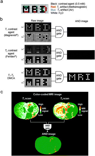 | ||
| Fig. 4 MRI artifact filtering capability of T1–T2 DMCAs. (a) The design of MRI phantom plate containing contrast agents and artifacts. (b) T1- and T2-weighted raw images of phantoms and final AND images. After an AND logic gate process, the T1–T2 DMCAs show the character “MRI” with complete filtration of artifacts in the AND image, while the conventional single-mode MRI contrast agents (Magnevist® and Feridex®) exhibit no signal. (c) Color-coded MRI images of the T1 and T2 scans of a rat brain injected with T1–T2 DMCA-labeled stem cells. The orange signals in the AND image are the areas with simultaneously high T1 and T2 MRI contrasts, which indicate the locations of the migrated stem cells. Reprinted with permission from ref. 30. Copyright 2014 American Chemical Society. | ||
T 1–T2 DMCAs combined with AND logic gates can be a useful tool for enhancing the accuracy of MR imaging of small biological targets, including tumors in early stage cancer, lymph nodes, and cardiovascular plaques, where various MRI artifacts are present.
3.2. MRI-optical dual-mode imaging agents
One of the traditional approaches to complementing the low sensitivity of MRI is the addition of optical fluorescence modalities. Various types of MRI-optical probes have been reported, where optically active components are chemically or physically combined with magnetic nanoparticles.16,31–34During early studies, MRI-optical dual-mode imaging agents have been constructed by conjugating fluorescent dyes to the surfaces of dextran-coated iron oxide nanoparticles.31 In a similar approach, MRI-optical probes are prepared by conjugating cyanine 5.5 (Cy5.5, λex = 649 nm, λem = 670 nm) to polymer-coated iron oxide nanoparticles (Fig. 5a).32 The dual imaging capability is successfully demonstrated in vivo with nanomolar sensitivity. However, combining the fluorescent units with magnetic nanoparticles often suffers from fluorescence quenching, which originates from energy transfer between the fluorescent molecules and the magnetic nanoparticles. This quenching phenomenon is highly dependent on the distance between the fluorophores and the nanoparticles, which decreases as the distance increases. Thus, strategies such as the utilization of long chemical linkers or a thick silica surface coating layer have been implemented.35 In a related approach, hybrid ‘core–satellite’ nanostructures are developed, where 30 nm dye-doped silica nanoparticles (‘core’) are decorated with multiple 9 nm iron oxide (Fe3O4) nanoparticles (‘satellite’) (Fig. 5b).16 The core–satellite dual imaging agents exhibit a 3.4-fold increase in the T2 MRI signal (r2 = 397 mM−1 s−1) compared with the individual nanoparticles (r2 = 116 mM−1 s−1) due to the nanoparticle clustering effects. The fluorescence signal is also enhanced by 1.7-fold compared with the directly dye-conjugated Fe3O4 nanoparticles. The ‘core–satellite’ MRI-optical dual-mode imaging agents enable sensitive imaging of sub-millimeter cellular clusters via both MRI and optical fluorescence imaging (Fig. 5c).
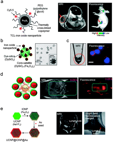 | ||
| Fig. 5 Magnetic nanoparticle-based MRI-optical dual-mode imaging agents. (a) Iron oxide nanoparticles labeled with fluorescent dyes (Cy5.5) visualize tumors with high T2 MRI signals (dark area in the red dotted circle) and fluorescence signals (red arrow). (b and c) ‘Core–satellite’ nanoparticles and their utilization in MRI-optical cancer cell imaging. (b) TEM image of ‘core–satellite’ nanoparticles composed of fluorescent dye-doped silica (DySiO2) and multiple surrounding iron oxide (Fe3O4) nanoparticles. (c) MRI and fluorescence imaging of human neuroblastoma cells (CHP-134) using the ‘core–satellite’ nanoparticles. The red and blue colors in the fluorescence image indicate the nanoparticles and the nuclei of the cells, respectively. (d) Assembly of NIR QDs with Fe3O4 nanoparticles via the biotin–streptavidin interaction allows for the imaging of mouse bladder with both high T2 MRI and NIR fluorescence signals. (e) UCNP-based nanoparticles composed of Fe3O4 and gold show the lymph node of a mouse via both T2 MRI and fluorescence imaging (λex = 980 nm, λem = 660 nm). (a) Reprinted with permission from ref. 32. Copyright 2007 American Chemical Society. (b and c) Reproduced from ref. 16 by permission of John Wiley & Sons Ltd. (d) Reprinted with permission from ref. 33. Copyright 2013 American Chemical Society. (e) Reproduced from ref. 34 by permission of John Wiley & Sons Ltd. | ||
Optically active components other than fluorescent dyes include quantum dots (QDs). Using QDs, it is possible to ensure a high fluorescence signal owing to their exceptional photostability, large extinction coefficients, and tunable absorption properties. One example is the assembly of multiple near-infrared (NIR) emitting QDs on Fe3O4 nanoparticles (Fig. 5d).33 NIR fluorescence offers deep tissue penetration capability, which allows high fluorescence sensitivity in deeply located organs such as the bladder. More recently, MRI-optical probes utilize NIR-to-visible upconversion nanoparticles (UCNPs) composed of lanthanide-doped rare-earth elements (Fig. 5e).34 UCNPs are known to possess high photostability, a narrow emission peak, and a deeper penetration depth. The use of NIR light as an excitation source prevents autofluorescence in UCNP-based optical imaging, which frequently arises from endogenous aromatic amino acid molecules (e.g. tryptophan, tyrosine, and phenylalanine) when short-wavelength (e.g. ultraviolet) radiation is used as an excitation source.
3.3. MRI–PET/SPECT dual-mode imaging agents
Another important multi-modal imaging system has been achieved via the combination of radioisotope-based imaging techniques (e.g. PET or SPECT) with MRI. These nuclear imaging techniques utilize gamma-rays emitted from decaying radioisotopes (e.g.18F, 64Cu, 68Ga, and 124I for PET and 99mTc, 111In, and 131I for SPECT). Generally, they offer high sensitivity, but have the limitation of relatively poor spatial resolution.2 Therefore, a combined MRI and PET/SPECT dual-modal system can provide highly resolved tomographic images along with strong sensitivity, leading to accurate determination of quantitative biological information, such as in vivo biodistribution and pharmacokinetics, particularly in deep tissues.19,36–39For the construction of MRI–PET/SPECT dual-mode imaging agents, magnetic nanoparticles have been modified with radioisotopes via chemical conjugation. One example is 124I linking via tyrosine residues of serum albumin coated on Mn-doped ferrite nanoparticles (Fig. 6a).36 The resultant MRI–PET dual imaging agents provide highly sensitive signals in both MRI and PET images. In an MRI–PET fused image, the two signals accurately delineate the different types of small sentinel lymph nodes of only a few millimeters in diameter. Another MRI–PET dual-mode imaging agent utilizes a macrocyclic chelating agent, DOTA (1,4,7,10-tetraazacyclododecane-N,N′,N′′,N′′′-tetraacetic acid), for radioisotope (64Cu) labeling and an arginine–glycine–aspartic acid (RGD) peptide for selective targeting of tumor integrin αvβ3.37 The conjugation of these functional moieties on polyaspartic acid-coated Fe3O4 nanoparticles allows in vivo targeted imaging of tumor xenografts by using both MRI and PET. Several robust radioisotope labeling strategies have also been developed. One example is the use of a bifunctional molecule composed of dithiocarbamate (DTC) and bisphosphonate (BP), which effectively chelates the radioisotope (64Cu) and simultaneously binds to the surfaces of magnetic nanoparticles (Endorem®), respectively (Fig. 6b).38 The final complex shows high stability under physiological conditions. The strong nanoparticle binding nature of BP can also be used to label radioisotopes for SPECT (Fig. 6c).19 By using the 99mTc modified BP that binds irreversibly to the surface of iron oxide nanoparticles, an MRI–SPECT dual-mode agent with high radiolabel stability is obtained. Another example is the chelator-free labeling of arsenic (As), which has four positron emitting radioisotopes (*As; * = 70, 71, 72, and 74) (Fig. 6d).39 Arsenic can be effectively labeled with magnetite by forming highly stable As complexes that occupy vacant tetrahedral sites of iron oxide. The dual imaging capabilities of those MRI–PET/SPECT imaging agents are successfully demonstrated in vivo imaging studies where lymph nodes (Fig. 6b), cardiovascular organs (Fig. 6c), and the liver (Fig. 6d) are detected with high sensitivity. In particular, the use of dual-mode imaging agents with the integration of MRI and PET/SPECT plays an important role as an imaging platform in highly sensitive and high resolution imaging in vivo.
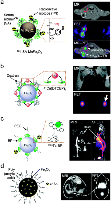 | ||
| Fig. 6 MRI–PET/SPECT dual-mode imaging agents with a magnetic nanoparticle platform. (a) Radioisotope-labeled Mn-doped ferrite nanoparticles (124I–SA–MnFe2O4) delineate the sentinel lymph nodes (axillary and brachial lymph nodes) with adequate PET signals and the anatomical MRI image. (b) Fe3O4 nanoparticles, which are labeled with radioisotope (64Cu) chelator molecules (DTCBP) enable detection of popliteal lymph nodes with both MRI and PET signals (white arrows). (c) 99mTc-labeled Fe3O4 nanoparticles for MRI–SPECT dual-modal imaging. Cardiovascular organs such as the heart and aorta are visualized in MRI and SPECT images. (d) Arsenic (As)-labeled iron oxide nanoparticles via a chelator-free synthetic route and their application in MRI and PET dual-modal imaging of liver (white arrows). (a, b, and d) Reproduced from ref. 36, 38, and 39 by permission of John Wiley & Sons Ltd. (c) Reprinted with permission from ref. 19. Copyright 2012 American Chemical Society. | ||
4. Magnetic nanoparticle-based non-traditional multi-modal imaging
In addition to the methods described above, during the past decade, magnetic nanoparticles have expanded their versatility in emerging multi-modal imaging techniques. Some examples are (i) magnetic particle imaging (MPI), (ii) magneto-motive ultrasound imaging (MMUS), and (iii) magneto-photoacoustic imaging (MPA). In conjunction with traditional imaging modalities (e.g. MRI and ultrasound (US) imaging) that provide anatomical information, new imaging modalities can be utilized to determine the location of magnetic nanoparticles in biological targets. Currently, MPI is combined with MRI, while MMUS and MPA are fused with US imaging. Because these new multi-modal imaging techniques all use magnetic nanoparticles as tracers, it is possible to achieve multi-modal imaging using only magnetic nanoparticles, without the need of tracers such as fluorescent molecules or radioisotopes. In the following sections, we will discuss the basic concepts of new multi-modal imaging techniques. The design considerations of magnetic nanoparticles for enhancing the image performance (sensitivity, resolution, and accuracy) of each technique will also be briefly discussed.4.1. MPI–MRI dual-modal imaging
MPI is a new imaging technique, which directly visualizes the spatial distribution of magnetic nanoparticles with several advantageous features.5,40,41 First, MPI is quantitative because the signal intensity of MPI is directly proportional to the concentration of magnetic nanoparticles. Second, MPI has no background signals because biological tissues and organs are diamagnetic and, thus, free from image ambiguities. Third, MPI can be used for real-time imaging because it has a fast imaging speed comparable to optical imaging and US imaging. Moreover, MPI is considered safe and has no penetration depth limit because it utilizes magnetic fields to perform the imaging measurements. Since the concept of MPI was introduced in 2005,5 this technique has been tested for cardiovascular system imaging, cell tracking, and diseases diagnosis. Currently, MPI in combination with MRI makes it possible to obtain sensitive and accurate information about nanoparticle location, while at the same time achieving high resolution anatomical imaging.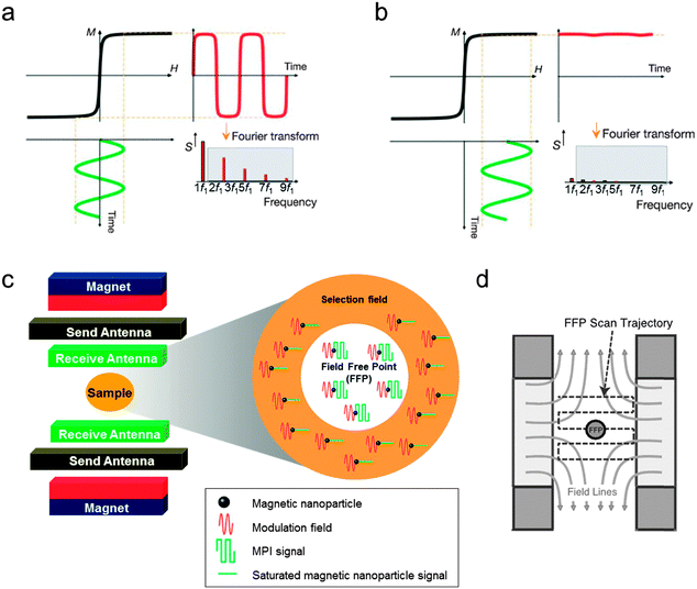 | ||
| Fig. 7 Basics of magnetic particle imaging (MPI). (a and b) Response of the magnetic nanoparticles to an external magnetic field. (a) When the modulation field (H, green curve) with a frequency of f1 is applied, time-dependent magnetization (M(t), red curve) and harmonics frequencies (S, red bars) are induced. The harmonics indicated by the grey box are used for MPI image generation. (b) When an additional time-independent external magnetic field (selection field) is added, the magnetic nanoparticles are magnetically saturated and the magnetization of the nanoparticles is not changed by the modulation field, resulting in neither M(t) nor S. (c) Schematic of the MPI instrument and the MPI signal generation. The magnet generates a selection field (orange region) that has a field-free point (FFP, white region) in the center. In addition, the send antenna creates a modulation field to magnetize the nanoparticles. The MPI signal produced by the magnetic nanoparticles located in the FFP is detected by the receive antenna. (d) Illustration of FFP raster scanning. (a and b) Reprinted with permission from Macmillan Publishers Ltd: ref. 5, copyright 2005. (c) Reproduced from ref. 41. (d) Reproduced from ref. 40 by permission of John Wiley & Sons Ltd. | ||
 | (3) |
 | (4) |
 | (5) |
Currently, the development of MPI tracers is still in its early stages and mainly focuses on the nanoparticle size effects on the MPI sensitivity and the resolution enhancement. Commercial iron oxide nanoparticles (Resovist®; core size = 4–6 nm, size distribution (σ) = 0.37) are tested (Fig. 8a), and the in vivo biodistribution of Resovist® is successfully visualized using MPI–MRI dual-modal imaging (Fig. 8b).40,42 A simulation study suggests that monodisperse 30 nm iron oxide nanoparticles can increase the MPI signal by 30-fold compared with Resovist®.5,42 Recently, several experimental studies have shown nanoparticle size effects. By synthesizing 20 nm Fe3O4 nanoparticles, it is possible to achieve a ca. 1.2-fold higher spatial resolution and a 4-fold higher sensitivity compared with Resovist® using an oscillating magnetic field of 25 kHz.42 Additionally, iron oxide nanoparticle-micelles (ION-Micelles), where 25 nm Fe3O4 nanoparticles are encapsulated in lipidic micelles (Fig. 8c), show an approximately 6 times higher MPI signal than the commercial iron oxide nanoparticles (Endorem®, Resovist®, and Sinerem®) in 25 kHz magnetic particle spectrometer measurements (Fig. 8d).43 The MPI signal can also be increased by clustering magnetic nanoparticles. Typically, multicore magnetic nanoparticles, which are clusters of small single iron oxide nanoparticles, show an MPI performance exceeding that of single nanoparticles.44 These examples clearly demonstrate the relationship between the quality of the MPI image and the size of the magnetic nanoparticle tracers. Additional studies on the other factors, including the magnetic core structures, compositions, and surface chemistry for molecular imaging capabilities, are necessary for the development of high performance nanoparticles for MPI–MRI dual-modal imaging.
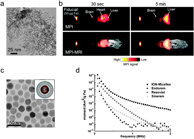 | ||
| Fig. 8 MPI–MRI dual-mode imaging agents. (a) TEM image of Resovist®. (b) Full-body MPI–MRI dual-modal imaging using Resovist® for the in vivo biodistribution study. Resovist® is observed in the brain, heart, and liver 30 sec after injection, followed by significant accumulation in the liver after 5 min. (c) TEM image and schematic illustration of ION-Micelles. (d) The MPI signal generating capabilities of the various iron oxide nanoparticles (ION-Micelles, Endorem®, Resovist®, and Sinerem®) as shown in the plot of the magnetic moment vs. the oscillating magnetic field frequency. The higher magnetic moment of ION-Micelles compared with the other nanoparticles over the entire frequency range allows for a stronger MPI signal. (a) Reprinted with permission from ref. 42. Copyright 2012, American Institute of Physics. (b) Reproduced from ref. 40 by permission of John Wiley & Sons Ltd. (c and d) Reproduced with permission from ref. 43. Copyright 2013 Starmans et al. | ||
4.2. Magnetic nanoparticle-assisted multi-modal ultrasound imaging
Ultrasound (US) imaging is one of the most widely used biomedical imaging techniques in clinical practice, such as angiography, echocardiography, and metastatic tumor detection.45 US has several advantages, including real-time imaging capability, high resolution, reasonable penetration depth, cost effectiveness, and portability. However, conventional US has a drawback due to its limited sensitivity. US contrast agents, such as liposomes, perfluorocarbon droplets, and microbubbles, have been examined, but their contrast enhancement effects are still insufficient to clearly detect subtle biological differences in pathology.46 Recent reports suggest that the sensitivity of US can also be improved by magnetic nanoparticles. This magnetic nanoparticle-assisted multi-modal US imaging is promising for visualizing biological events at the cellular and molecular level in real time. Two representative multi-modal US imaging techniques have been introduced: (i) magneto-motive ultrasound (MMUS)–US and (ii) magneto-photoacoustic (MPA)–US.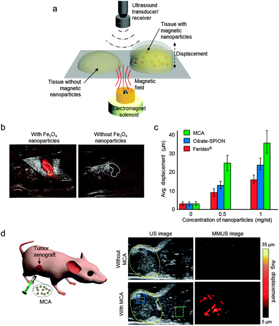 | ||
| Fig. 9 Magneto-motive ultrasound (MMUS)–US dual-modal imaging. (a) Magnetically induced displacement of the tissue embedded with magnetic nanoparticles generates a MMUS signal, which is detected using an ultrasound receiver. (b) The MMUS–US dual-modal imaging of sentinel lymph nodes (SNL, white solid line). In the presence of Fe3O4 nanoparticles, the SNL is shown with color-coded MMUS signal, while the SNL without Fe3O4 shows no MMUS signal. (c) Comparisons of the MMUS signals from various magnetic nanoparticles. The MMUS signal of MCA (15 nm Zn-doped ferrite nanoparticle) is ca. 2–3-fold higher than that of citrate-SPION and Feridex®. (d) In vivo US and MMUS images of a mouse with a tumor xenograft. Upon injection of MCA, MMUS signals clearly represent the tumor location marked by yellow dashed lines. (a, c, and d) Reproduced from ref. 6. (b) © [2014] IEEE. Reprinted with permission from ref. 47. | ||
The relationship between the MMUS signal intensity and the susceptibility of the magnetic nanoparticles is shown in eqn (6)
 | (6) |
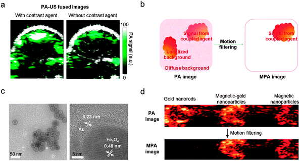 | ||
| Fig. 10 Photoacoustic (PA) imaging accuracy enhancement via magneto-photoacoustic (MPA) imaging. (a) Conventional PA–US dual-modal imaging of tumors in a mouse using the PA contrast agent shows an increase of the PA signal (green). Non-negligible PA signals, which originate from background photoacoustic absorbers, are also observed in PA–US image without a contrast agent. (b) Schematic illustration of the background signal elimination via a motion filtering process. Only magnetic nanoparticle-based imaging agents that respond to a pulsed magnetic field can be distinguished from the background photoacoustic absorbers. (c) TEM images of the magnetic-gold nanoparticles. (d) Magnetic-gold nanoparticles and magnetic nanoparticles show strong MPA signals, while the signals from the gold nanorods that mimic the background is completely eliminated. (a) Reprinted with permission from ref. 49. Copyright 2010 American Chemical Society. (b–d) Reprinted with permission from Macmillan Publishers Ltd: ref. 7, copyright 2010. | ||
Recently, the combination of PA with magnetic nanoparticles, so-called magneto-PA (MPA), is reported as an approach to enhance the quality of PA–US dual-modal imaging.7 When a pulsed external magnetic field is applied during PA image acquisition, the magnetic nanoparticles create a vibrating motion while non-magnetic endogenous photoabsorbers remain still. By detecting the motion of the nanoparticles, the PA signals from the nanoparticles can be distinguished from the background (Fig. 10b).7 This background elimination capability of MPA is demonstrated using 25 nm Fe3O4 nanoparticles and magnetic-gold core–shell nanoparticles (Fig. 10c). In the phantom experiments, both the magnetic nanoparticles and the magnetic-gold core–shell nanoparticles are successfully differentiated from gold nanorods, which are used as a control for the background signal (Fig. 10d). Another example of magnetic nanoparticle-aided PA imaging utilizes the principle of magnetic nanoparticle clustering (Fig. 11a and b).50 Compared with single magnetic nanoparticles, clustered magnetic nanoparticles show a higher PA signal than the background signal (Fig. 11b). Based on this principle, magnetic nanoparticle-labeled tumor cells under flow conditions are successfully captured and further detected using PA imaging (Fig. 11c and d). These cell capturing and PA signal boosting capabilities of magnetic nanoparticles are further utilized in the detection of tumor cells circulating in vivo, which are some of the important biomarkers of cancer metastasis.
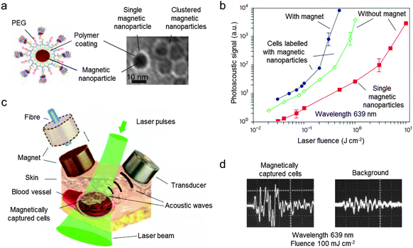 | ||
| Fig. 11 Magnetic nanoparticle-assisted photoacoustic (PA) imaging. (a) Schematic illustration of a polymer-coated magnetic nanoparticle and the TEM image of single and clustered magnetic nanoparticles. (b) Comparison of the photoacoustic signals of cells labeled with clustered magnetic nanoparticles (blue), cells labeled with single magnetic nanoparticles (green), and single magnetic nanoparticles (red). The higher PA signal of the clustered magnetic nanoparticles over the single nanoparticles is observed. (c) Illustration of magnetic cell capturing and the PA imaging setup. (d) The magnetically captured cells show a strong PA signal than the background. Reprinted with permission from Macmillan Publishers Ltd: ref. 50, copyright 2009. | ||
5. Conclusions and outlook
In this review, we discussed recent advances of magnetic nanoparticles for various biomedical imaging modalities. Metal ferrite nanoparticles can be used as either T1 or T2 MRI contrast agents. By controlling the magnetism of the nanoparticles via size, composition, and shape, the MRI contrast effects can be enhanced to achieve highly sensitive MRI. Complementary combinations of various types of materials (e.g. fluorescent molecules and radioisotopes) provide nanoparticles with multi-modal imaging capabilities. Moreover, magnetic nanoparticles have become a platform for the new types of contrast agents used in emerging imaging technologies such as MPI, MMUS, and MPA. These magnetic nanoparticle-based multi-modal imaging approaches hold new promise to secure enhanced imaging sensitivity and accuracy for a better understanding of biological systems and accurate imaging of biological targets.Acknowledgements
This work was supported by the National Creative Research Initiative (2010-0018286) and the Korea Healthcare Technology R&D Project, Ministry for Health & Welfare Affairs (HI08C2149). We thank Dr Dongwon Yoo for helpful discussion.References
- E. T. Ahrens and J. W. M. Bulte, Nat. Rev. Immunol., 2013, 13, 755–763 CrossRef CAS PubMed.
- D.-E. Lee, H. Koo, I.-C. Sun, J. H. Ryu, K. Kim and I. C. Kwon, Chem. Soc. Rev., 2012, 41, 2656–2672 RSC.
- J. Cheon and J.-H. Lee, Acc. Chem. Res., 2008, 41, 1630–1640 CrossRef CAS PubMed.
- H. B. Na, I. C. Song and T. Hyeon, Adv. Mater., 2009, 21, 2133–2148 CrossRef CAS.
- B. Gleich and J. Weizenecker, Nature, 2005, 435, 1214–1217 CrossRef CAS PubMed.
- M. Mehrmohammadi, T.-H. Shin, M. Qu, P. Kruizinga, R. L. Truby, J.-H. Lee, J. Cheon and S. Y. Emelianov, Nanoscale, 2013, 5, 11179–11186 RSC.
- Y. Jin, C. Jia, S.-W. Huang, M. O'Donnell and X. Gao, Nat. Commun., 2010, 1, 41–48 Search PubMed.
- C. P. Slichter, Principles of Magnetic Resonance, Springer, New York, 3rd edn, 1990 Search PubMed.
- S. Tong, S. Hou, Z. Zheng, J. Zhou and G. Bao, Nano Lett., 2010, 10, 4607–4613 CrossRef CAS PubMed.
- B. H. Kim, N. Lee, H. Kim, K. An, Y. I. Park, Y. Choi, K. Shin, Y. Lee, S. G. Kwon, H. B. Na, J.-G. Park, T.-Y. Ahn, Y.-W. Kim, W. K. Moon, S. H. Choi and T. Hyeon, J. Am. Chem. Soc., 2011, 133, 12624–12631 CrossRef CAS PubMed.
- A. Roch, R. N. Muller and P. Gillis, J. Chem. Phys., 1999, 110, 5403–5411 CrossRef CAS PubMed.
- R. A. Brooks, Magn. Reson. Med., 2002, 47, 388–391 CrossRef CAS PubMed.
- Y.-w. Jun, Y.-M. Huh, J.-s. Choi, J.-H. Lee, H.-T. Song, S. Kim, S. Yoon, K.-S. Kim, J.-S. Shin, J.-S. Suh and J. Cheon, J. Am. Chem. Soc., 2005, 127, 5732–5733 CrossRef CAS PubMed.
- J.-s. Choi, J.-H. Lee, T.-H. Shin, H.-T. Song, E. Y. Kim and J. Cheon, J. Am. Chem. Soc., 2010, 132, 11015–11017 CrossRef CAS PubMed.
- S. Balasubramaniam, S. Kayandan, Y.-N. Lin, D. F. Kelly, M. J. House, R. C. Woodward, T. G. St. Pierre, J. S. Riffle and R. M. Davis, Langmuir, 2014, 30, 1580–1587 CrossRef CAS PubMed.
- J.-H. Lee, Y.-w. Jun, S.-I. Yeon, J.-S. Shin and J. Cheon, Angew. Chem., Int. Ed., 2006, 45, 8160–8162 CrossRef CAS PubMed.
- J. M. Perez, L. Josephson, T. O'Loughlin, D. Hogemann and R. Weissleder, Nat. Biotechnol., 2002, 20, 816–820 CrossRef CAS PubMed.
- J. B. Haun, T.-J. Yoon, H. Lee and R. Weissleder, Wiley Interdiscip. Rev.: Nanomed. Nanobiotechnol., 2010, 2, 291–304 CrossRef CAS PubMed.
- L. Sandiford, A. Phinikaridou, A. Protti, L. K. Meszaros, X. Cui, Y. Yan, G. Frodsham, P. A. Williamson, N. Gaddum, R. M. Botnar, P. J. Blower, M. A. Green and R. T. M. de Rosales, ACS Nano, 2012, 7, 500–512 CrossRef PubMed.
- J.-H. Lee, Y.-M. Huh, Y.-w. Jun, J.-w. Seo, J.-t. Jang, H.-T. Song, S. Kim, E.-J. Cho, H.-G. Yoon, J.-S. Suh and J. Cheon, Nat. Med., 2007, 13, 95–99 CrossRef CAS PubMed.
- J.-t. Jang, H. Nah, J.-H. Lee, S. H. Moon, M. G. Kim and J. Cheon, Angew. Chem., Int. Ed., 2009, 48, 1234–1238 CrossRef CAS PubMed.
- Z. Zhou, L. Wang, X. Chi, J. Bao, L. Yang, W. Zhao, Z. Chen, X. Wang, X. Chen and J. Gao, ACS Nano, 2013, 7, 3287–3296 CrossRef CAS PubMed.
- J. W. M. Bulte and D. L. Kraitchman, NMR Biomed., 2004, 17, 484–499 CrossRef CAS PubMed.
- J. G. Penfield and R. F. Reilly, Nat. Clin. Pract. Nephrol., 2007, 3, 654–668 Search PubMed.
- Z. Zhao, Z. Zhou, J. Bao, Z. Wang, J. Hu, X. Chi, K. Ni, R. Wang, X. Chen, Z. Chen and J. Gao, Nat. Commun., 2013, 4, 2266–2272 Search PubMed.
- Z. Zhou, Z. Zhao, H. Zhang, Z. Wang, X. Chen, R. Wang, Z. Chen and J. Gao, ACS Nano, 2014, 8, 7976–7985 CrossRef CAS PubMed.
- K. H. Bae, Y. B. Kim, Y. Lee, J. Hwang, H. Park and T. G. Park, Bioconjugate Chem., 2010, 21, 505–512 CrossRef CAS PubMed.
- Z. Zhou, D. Huang, J. Bao, Q. Chen, G. Liu, Z. Chen, X. Chen and J. Gao, Adv. Mater., 2012, 24, 6223–6228 CrossRef CAS PubMed.
- G. Huang, H. Li, J. Chen, Z. Zhao, L. Yang, X. Chi, Z. Chen, X. Wang and J. Gao, Nanoscale, 2014, 6, 10404–10412 RSC.
- T.-H. Shin, J.-s. Choi, S. Yun, I.-S. Kim, H.-T. Song, Y. Kim, K. I. Park and J. Cheon, ACS Nano, 2014, 8, 3393–3401 CrossRef CAS PubMed.
- L. Josephson, M. F. Kircher, U. Mahmood, Y. Tang and R. Weissleder, Bioconjugate Chem., 2002, 13, 554–560 CrossRef CAS PubMed.
- H. Lee, M. K. Yu, S. Park, S. Moon, J. J. Min, Y. Y. Jeong, H.-W. Kang and S. Jon, J. Am. Chem. Soc., 2007, 129, 12739–12745 CrossRef CAS PubMed.
- E. S. Shibu, K. Ono, S. Sugino, A. Nishioka, A. Yasuda, Y. Shigeri, S.-i. Wakida, M. Sawada and V. Biju, ACS Nano, 2013, 7, 9851–9859 CrossRef CAS PubMed.
- L. Cheng, K. Yang, Y. Li, J. Chen, C. Wang, M. Shao, S.-T. Lee and Z. Liu, Angew. Chem., Int. Ed., 2011, 50, 7385–7390 CrossRef CAS PubMed.
- H. Ow, D. R. Larson, M. Srivastava, B. A. Baird, W. W. Webb and U. Wiesner, Nano Lett., 2004, 5, 113–117 CrossRef PubMed.
- J.-s. Choi, J. C. Park, H. Nah, S. Woo, J. Oh, K. M. Kim, G. J. Cheon, Y. Chang, J. Yoo and J. Cheon, Angew. Chem., Int. Ed., 2008, 47, 6259–6262 CrossRef CAS PubMed.
- H.-Y. Lee, Z. Li, K. Chen, A. R. Hsu, C. Xu, J. Xie, S. Sun and X. Chen, J. Nucl. Med., 2008, 49, 1371–1379 CrossRef CAS PubMed.
- R. Torres Martin de Rosales, R. Tavaré, R. L. Paul, M. Jauregui-Osoro, A. Protti, A. Glaria, G. Varma, I. Szanda and P. J. Blower, Angew. Chem., Int. Ed., 2011, 50, 5509–5513 CrossRef PubMed.
- F. Chen, P. A. Ellison, C. M. Lewis, H. Hong, Y. Zhang, S. Shi, R. Hernandez, M. E. Meyerand, T. E. Barnhart and W. Cai, Angew. Chem., Int. Ed., 2013, 52, 13319–13323 CrossRef CAS PubMed.
- P. W. Goodwill, E. U. Saritas, L. R. Croft, T. N. Kim, K. M. Krishnan, D. V. Schaffer and S. M. Conolly, Adv. Mater., 2012, 24, 3870–3877 CrossRef CAS.
- M. H. Pablico-Lansigan, S. F. Situ and A. C. S. Samia, Nanoscale, 2013, 5, 4040–4055 RSC.
- R. M. Ferguson, A. P. Khandhar and K. M. Krishnan, J. Appl. Phys., 2012, 111, 07B318 CrossRef PubMed.
- L. W. E. Starmans, D. Burdinski, N. P. M. Haex, R. P. M. Moonen, G. J. Strijkers, K. Nicolay and H. Grüll, PLoS One, 2013, 8, e57335 CAS.
- D. Eberbeck, F. Wiekhorst, S. Wagner and L. Trahms, Appl. Phys. Lett., 2011, 98, 182502 CrossRef PubMed.
- T. L. Szabo, Diagnostic Ultrasound Imaging: Inside Out, Elsevier Academic Press, San Diego, 2004 Search PubMed.
- M. Mehrmohammadi, J. Oh, S. Mallidi and S. Y. Emelianov, Mol. Imaging, 2011, 10, 102–110 Search PubMed.
- M. Evertsson, P. Kjellman, M. Cinthio, S. Fredriksson, R. in't Zandt, H. Persson and T. Jansson, IEEE Trans. Ultrason., Ferroelectr., Freq. Control., 2014, 61, 1276–1283 CrossRef PubMed.
- L. V. Wang and S. Hu, Science, 2012, 335, 1458–1462 CrossRef CAS PubMed.
- A. d. l. Zerda, Z. Liu, S. Bodapati, R. Teed, S. Vaithilingam, B. T. Khuri-Yakub, X. Chen, H. Dai and S. S. Gambhir, Nano Lett., 2010, 10, 2168–2172 CrossRef PubMed.
- E. I. Galanzha, E. V. Shashkov, T. Kelly, J.-W. Kim, L. Yang and V. P. Zharov, Nat. Nanotechnol., 2009, 4, 855–860 CrossRef CAS PubMed.
| This journal is © The Royal Society of Chemistry 2015 |


