 Open Access Article
Probing morphological changes in polymersomes with magnetic birefringence†
Roger S. M.
Rikken
ab,
Harmen H. M.
Kerkenaar
ab,
Roeland J. M.
Nolte
b,
Jan C.
Maan
a,
Jan C. M.
van Hest
b,
Peter C. M.
Christianen
a and
Daniela A.
Wilson
*b
aHigh Field Magnet Laboratory (HFML), Radboud University Nijmegen, Toernooiveld 7, 6525 ED Nijmegen, The Netherlands. E-mail: p.christianen@science.ru.nl
bInstitute of Molecules and Materials, Radboud University Nijmegen, Heyendaalseweg 135, 6525 AJ, Nijmegen, The Netherlands. E-mail: d.wilson@science.ru.nl
First published on 24th October 2013
Abstract
Magnetic birefringence was used for in situ monitoring of the morphological changes in diamagnetic polymersomes during shape-transformation by dialysis. The birefringence was found to be very sensitive to the polymersome morphology, as determined by electron microscopy. The deflation of polymersomes into disks was observed, followed by a bending and partial inflation into stomatocytes.
Amphiphilic block-copolymers can self-assemble in water into bilayer vesicles named polymersomes.1 Many properties of these polymersomes, such as flexibility, permeability and functionality, can be tuned by varying the type or length of either the hydrophobic or the hydrophilic part of the block-copolymer1 or by adding functional groups to make them stimuli responsive.2 Flexibility and permeability can also be affected by the addition of an organic solvent, such as tetrahydrofuran (THF), which acts as a plasticizer for the hydrophobic part of the polymersome membrane.3,4 It has been previously demonstrated that polymersomes, self-assembled from poly(ethylene glycol)–polystyrene (PEG–PS) in a mixture of THF, 1,4-dioxane and water, undergo shape transformations into bowl-shaped structures called stomatocytes by dialysis against pure water.5a Also the conformation of these stomatocytes could be further manipulated by reverse dialysis against a mixture of water, THF and dioxane.5b This control over morphology has led to nanoparticle encapsulation by the stomatocytes6 and their supramolecular assembly to give stomatocyte nanorockets.7 These properties make polymersomes and stomatocytes very promising candidates as nanocontainers in drug delivery or nanochemistry.
Until now, the effect of dialysis on the morphology of the polymersomes or stomatocytes has been investigated by taking samples at regular intervals followed by the ex situ imaging of their conformations using electron microscopy. Here, we demonstrate how the morphology of polymersomes during dialysis can be probed in a continuous and non-invasive way using in situ magnetic birefringence. These measurements clearly reveal the exact times at which the morphology of the polymersomes change, making it possible to take samples for electron microscopy at the crucial points of dialysis.
Magnetic birefringence can be observed upon the alignment of molecules or aggregates. Even seemingly non-magnetic matter (like the vast majority of polymers and biomolecules) is in fact weakly magnetic (diamagnetic). Molecules used for self-assembly are usually anisotropic in shape, leading to a magnetic response that is also anisotropic. These molecules therefore have a preferential orientation in a magnetic field. The difference in energy between two orthogonal orientations of a molecule is normally quite small and hence the alignment is largely randomized by thermal motion. However, when these molecules form aggregates or self-assemble into supramolecular structures, the total diamagnetic anisotropy can be enhanced significantly.8 This principle has been used to orient organic nanostructures composed of a wide variety of molecules, including polymers.9–12 The diamagnetic anisotropy, and hence the magnetic alignment, of these self-assembled structures is also related to their overall shape. For instance, a sphere with an isotropic orientational distribution of molecules has no preferential axis of alignment. However, when the distribution of molecular orientations is anisotropic magnetic alignment can occur. For example, a disk constructed from diamagnetic anisotropic molecules aligns with its surface either parallel or perpendicular to the magnetic field, depending on the sign of the diamagnetic anisotropy of the molecular building blocks.
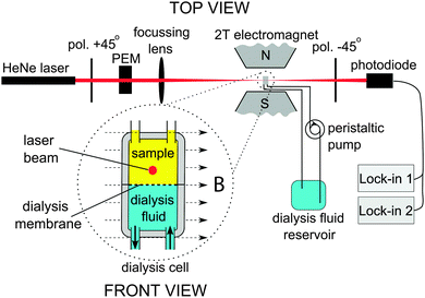
Magnetic orientation of supramolecular aggregates in solution results in a difference in the refractive index for light polarized parallel and perpendicular with respect to the magnetic field. This magnetic birefringence has been frequently measured to determine the degree of alignment of various aggregates in magnetic fields.9–12 In this communication, we use magnetic birefringence to probe morphological changes in polymersomes during dialysis, while further insight into the mechanism of osmotically induced shape change is presented. To explore the morphological changes we implemented a dialysis cell with a magnetic birefringence setup in a 2 T magnet (Fig. 1). Light of a HeNe laser (1.5 mW, 632.8 nm) was focussed on the upper chamber of a flow cell, which contained a PEG44–PS133 polymersome sample. Initially the sample consisted of spherical polymersomes in pure water, having a radius of 252 nm and a PDI of 0.134, as determined by dynamic light scattering (DLS). A dialysis fluid consisting of 50% water, 40% THF and 10% 1,4-dioxane was pumped through the bottom chamber at a rate of 100 mL h−1. The chambers were separated by a 12–14 kDa cut-off membrane. The magnetic birefringence was detected using a standard polarization modulation technique.13,14
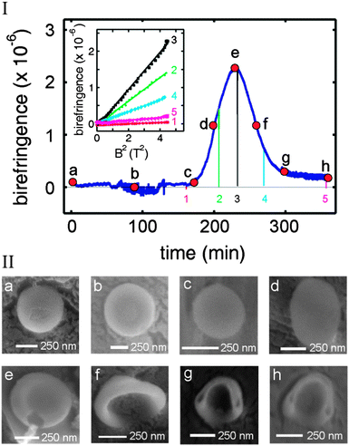
The birefringence was measured over a time interval of 360 minutes (blue curve in Fig. 2I). At the beginning of the experiment, the birefringence remained zero up to 170 minutes (point c), after which a rapid increase in the signal was observed. A maximum was reached at 230 minutes (point e), after which the birefringence decreased. From point g onwards, the sample showed a small birefringence, which remained constant until the end of the measurement (point h). At certain time points, magnetic field sweeps were performed where the magnetic field was reduced to zero and subsequently brought back to 2 T (indicated in Fig. 2I by the coloured lines 1–5). The field sweeps were sufficiently rapid (about one minute) to allow the subsequent birefringence signal to remain unchanged by the continuous dialysis. The birefringence always decreased to zero when the magnetic field was brought to zero. Restoring the field to 2 T also resulted in recovery of the birefringence to the same value before the field sweep, showing that the measured signal is not caused by drift. The inset of Fig. 2I shows the birefringence as a function of B2. All curves scale quadratically with the applied magnetic field, implying a non-saturated magnetic alignment. This is usually observed in the low magnetic field regime where the competition with thermal motion tends to randomize the orientation of the molecules resulting in partial alignment with the field.
Measuring magnetic birefringence during dialysis offers the opportunity to stop dialysis at well-defined points to take samples for further investigation by electron microcopy. In this manner, the morphology can be related to the amplitude of the birefringence signal. Samples were taken at points a–h as indicated by the red dots in Fig. 2I (ESI†).
Cryogenic-Scanning Electron Microscopy (cryo-SEM) images of samples (a–h) are shown in Fig. 2II. At the beginning of dialysis, polymersomes were present with the expected spherical morphology (point a) corresponding to zero birefringence. At points b and c, no changes in conformation were observed, in agreement with the measured constant magnetic birefringence. At point d the birefringence increased to half its maximal value. The cryo-SEM images show ellipsoidal polymersomes, which can only be explained by a partial deflation of the spherical polymersomes. When the birefringence reached a maximum (point e), flat disks were observed under a cryo-SEM. Continuation of the dialysis led to the bending of the flat disks (point f) and the formation of stomatocytes (points g and h), where the structures partly inflated again. At this point, the hydrodynamic radius of the polymersomes was decreased to 218 nm with a PDI of 0.12, as determined by DLS (see ESI†).
At all points, the magnitude of the birefringence reflects the shape of the structures. All spherical polymersomes show zero birefringence since they cannot be aligned.15 With increasing deflation of the polymersomes the birefringence amplitude increases. The largest birefringence is observed for disks, in which most of the polymers have identical orientation, perpendicular to the flat surface. The transition of disks to stomatocytes leads to a more curved conformation, and hence a smaller diamagnetic anisotropy.
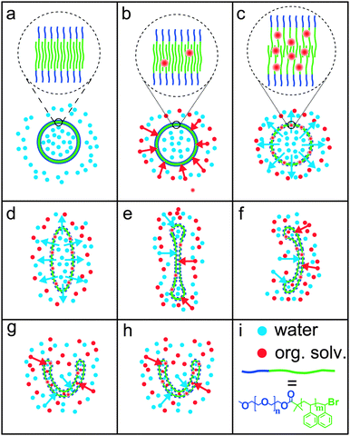
To explain the effects of dialysis on the morphology of the polymersomes, we propose the mechanism depicted in Scheme 1. At the starting point of the dialysis, the polymersome membrane is very rigid, due to lack of a plasticising organic solvent (a). During dialysis, the organic solvent (red dots) enters the polymersome membrane (b). At point c, enough organic solvent has entered the hydrophobic part of the polymersome membrane to make it permeable to water (blue dots). From this point on, water diffuses out of the polymersome, as a result of the concentration gradient over the membrane. The outflow of water leads to a reduced inner volume, giving rise to an elongated shape (d). Further outflow of water eventually leads to a disk, which shows the highest birefringence (e). At this point the disk begins to bend in one direction, most probably due to fluctuations in the membrane that give rise to a spontaneous curvature. The membrane starts to fill slowly with the mixture of water and organic solvent again (f). This process continues and stomatocytes are formed (g, h).
 | ||
| Scheme 1 (a–h) Proposed mechanism of the dialysis of polymersomes against 50% water, 40% THF and 10% 1,4-dioxane. The morphologies correspond to those shown in Fig. 2II. In (a–c), the polymersome membrane is shown enlarged. The organic solvent acts as a plasticiser, which swells the membrane. Swollen membranes are indicated by dashed lines in figures (c–h) compared to the solid lines in figures (a) and (b). (i) Red and blue dots represent organic solvent and water, respectively. The block co-polymer is drawn schematically as a short blue line (PEG) connected to a longer green line (PS). | ||
In conclusion, we have demonstrated that magnetic birefringence can be used as a useful tool to monitor morphological changes in polymersomes resulting from dialysis in a flow cell. This method has the advantage of being non-invasive; while the morphology can be determined without disrupting the dialysis setup for sample investigation by electron microscopy. Also, because the dialysis in the flow cell is rather slow (in the order of several hours), the shape transformations can be determined at very precise points on the birefringence curve, providing samples with very specific and predictable conformations. In principle, this method could be extended to obtain more quantitative information about the rigidity of the structures in all stages of the process. However this would require a more extended theoretical analysis.
We acknowledge the support of the HFML-RU/FOM, member of the European Magnetic Field Laboratory (EMFL). R. S. M. Rikken acknowledges the Graduate School for Molecules and Materials for a PhD position and NWO for its corresponding grant. D. A. Wilson acknowledges funding from the European Research Council under the European Union's Seventh Framework Programme (FP7/2007-2012)/ERC-StG 307679 “StomaMotors”. R. J. M. Nolte acknowledges support from the European Research Council (ERC Advanced grant 290886-ALPROS) and R. J. M. Nolte and J. C. M. van Hest acknowledge support from the Ministry of Education, Culture and Science (Gravity program 024.001.035). Finally, we would like to thank G.-J. Janssen for his assistance with the electron microscopes and P. Walraven for the fabrication of the flow cell.
Notes and references
- D. E. Discher and F. Ahmed, Annu. Rev. Biomed. Eng., 2006, 8, 323 CrossRef CAS PubMed.
- F. Meng, Z. Zhong and J. Feijen, Biomacromolecules, 2009, 10, 197 CrossRef CAS PubMed.
- S. J. Holder and N. A. J. M. Sommerdijk, Polym. Chem., 2011, 2, 1018 RSC.
- Y. Yu and A. Eisenberg, J. Am. Chem. Soc., 1997, 119, 8383–8384 CrossRef CAS.
- (a) K.-T. Kim, J. Zhu, S. A. Meeuwissen, J. J. L. M. Cornelissen, D. J. Pochan, R. J. M. Nolte and J. C. M. van Hest, J. Am. Chem. Soc., 2010, 132, 12522 CrossRef CAS PubMed; (b) S. A. Meeuwissen, K. Kim, Y. Chen, D. J. Pochan and J. C. M. van Hest, Angew. Chem., Int. Ed., 2011, 50, 7070 CrossRef CAS PubMed.
- D. A. Wilson, R. J. M. Nolte and J. C. M. van Hest, J. Am. Chem. Soc., 2012, 134, 9894 CrossRef CAS PubMed.
- (a) D. A. Wilson, R. J. M. Nolte and J. C. M. van Hest, Nat. Chem., 2012, 4, 268 CrossRef CAS PubMed; (b) D. A. Wilson, B. de Nijs, A. van Blaaderen, R. J. M. Nolte and J. C. M. van Hest, Nanoscale, 2013, 5, 1315 RSC.
- R. Rikken, R. J. M. Nolte, J. C. Maan, J. C. M. van Hest, D. A. Wilson and P. C. M. Christianen, Soft Matter, 2013 10.1039/C3SM52294F.
- I. O. Shklyarevskiy, M. I. Boamfa, P. C. M. Christianen, F. Touhari, H. van Kempen, G. Deroover, P. Callant and J. C. Maan, J. Chem. Phys., 2002, 116, 8407 CrossRef CAS.
- P. C. M. Christianen, I. O. Shklyarevskiy, M. I. Boamfa and J. C. Maan, Phys. Biol., 2004, 346–347, 255 CAS.
- J. C. Gielen, M. Wolffs, G. Portale, W. Bras, O. Henze, A. F. M. Kilbinger, W. J. Feast, J. C. Maan, A. P. H. J. Schenning and P. C. M. Christianen, Langmuir, 2009, 25, 1272 CrossRef CAS PubMed.
- J. C. Gielen, I. O. Shklyarevskiy, A. P. H. J. Schenning, P. C. M. Christianen and J. C. Maan, Sci. Technol. Adv. Mater., 2009, 10, 014601 CrossRef.
- G. Maret and K. Dransfeld, Strong and Ultrastrong Magnetic Fields and Their Applications, Springer-Verlag, Berlin, 1985, ch. 4 Search PubMed.
- J. C. Kemp, Polarized Light and its Interaction with Modulated Devices – A Methodology Review, HINDS International Inc., Hillsboro, 1987 Search PubMed.
- This indicates that the PEG–PS polymersomes are not yet deformed at 2 T. Magnetic deformation of other nanocapsules has been observed at higher magnetic fields up to 20 T: I. O. Shklyarevskiy, P. Jonkheijm, P. C. M. Christianen, A. P. H. J. Schenning, E. W. Meijer, O. Henze, F. M. Kibinger, W. J. Feast, A. Del Guerzo, J. P. Desvergne and J. C. Maan, J. Am. Chem. Soc., 2005, 127, 1112 CrossRef CAS PubMed.
Footnote |
| † Electronic supplementary information (ESI) available: Materials and instrumentation, polymersome sample preparation, statistics on points c, e and h, DLS and TEM/SEM-images at points a–h on the birefringence curve. See DOI: 10.1039/c3cc47483f |
| This journal is © The Royal Society of Chemistry 2014 |


