
 Open Access Article
 This Open Access Article is licensed under a Creative Commons Attribution-Non Commercial 3.0 Unported Licence
Green and sustainable zero-waste conversion of water hyacinth (Eichhornia crassipes) into superior magnetic carbon composite adsorbents and supercapacitor electrodes†
Amonrada Saninga,
Servann Heroub,
Decha Dechtrirat c,
Chanoknan Ieosakulratd,
Pasit Pakawatpanurutd,
Sulawan Kaowphonge,
Chanchana Thanachayanontf,
Maria-Magdalena Titiricibg and
Laemthong Chuenchom*a
c,
Chanoknan Ieosakulratd,
Pasit Pakawatpanurutd,
Sulawan Kaowphonge,
Chanchana Thanachayanontf,
Maria-Magdalena Titiricibg and
Laemthong Chuenchom*a
aDepartment of Chemistry and Center of Excellence for Innovation in Chemistry (PERCH-CIC), Faculty of Science, Prince of Songkla University, Hat-Yai, Songkhla 90112, Thailand. E-mail: laemthong.c@psu.ac.th
bDepartment of Chemical Engineering, Imperial College London, South Kensington Campus, SW7 2AZ, UK
cDepartment of Materials Science, Faculty of Science, Kasetsart University, Ngam Wong Wan Road, Lat Yao, Chatuchak, Bangkok 10900, Thailand
dDepartment of Chemistry and Center of Excellence for Innovation in Chemistry (PERCH-CIC), Faculty of Science, Mahidol University, Rama VI Rd, Bangkok 10400, Thailand
eDepartment of Chemistry, Faculty of Science, Chiang Mai University, Chiang Mai 50200, Thailand
fNational Metal and Materials Technology Center (MTEC), National Science and Technology Development Agency (NSTDA), Pathumthani 12120, Thailand
gSchool of Engineering and Materials Science, Queen Mary University of London, Mile End Road, E1 4NS, London, UK
First published on 5th August 2019
Abstract
Troublesome aquatic weed, water hyacinth (Eichhornia crassipes) was converted into solid and liquid fractions via green and energy-saving hydrothermal carbonization (HTC). The solid product, hydrochar, was employed as a precursor to prepare magnetic carbon materials by simple activation and magnetization using KOH and Fe3+ ions, respectively. The obtained magnetic adsorbent possessed good magnetic properties and presented outstanding capacities to adsorb methylene blue (524.20 mg g−1), methyl orange (425.15 mg g−1) and tetracycline (294.24 mg g−1) with rapid adsorption kinetics even at high concentrations (up to 500 mg L−1), attributed to high specific surface area and mesopore porosity. Besides the solid hydrochar, the water-soluble liquid product was used to fabricate carbon-based supercapacitors through facile KOH activation with a considerably lower KOH amount in comparison to conventional activation. The supercapacitor electrode made from activated liquid product possessed an extremely high specific surface area of 2545 cm2 g−1 and showed excellent specific capacitance (100 F g−1 or 50 F cm−3 at 1 A g−1) and good retention of capacitance (92% even after 10![[thin space (1/6-em)]](https://www.rsc.org/images/entities/char_2009.gif) 000 cycles). This work demonstrated that both solid and liquid HTC fractions from this bio-waste can serve as effective sources to prepare functional carbon materials, making this approach a sustainable zero-waste biomass conversion process.
000 cycles). This work demonstrated that both solid and liquid HTC fractions from this bio-waste can serve as effective sources to prepare functional carbon materials, making this approach a sustainable zero-waste biomass conversion process.
Introduction
Water hyacinth (WH, Eichhornia crassipes) is a floating aquatic weed originating from South America. It is considered an invasive species that has spread around the world. In many countries, including Thailand, Indonesia, and China, WH reproduces very quickly, covering large water bodies including rivers, lakes and canals, impeding water flow, and starving the water of oxygen. This often kills fish and other species and reduces biodiversity.1 It has been reported that it takes only one day to reproduce over one-fourth of a ton of dried WH per hectare.1 Nowadays, attempts at beneficial utilization of WH have been spent mostly on handicraft products2 and fertilizers.3 However, regarding the economic merits of this approach, such products do not provide much value. The real problem is that WH grows at a rate that surpasses its consumption. Therefore, to address this problem in an economically viable fashion, WH needs new innovative uses.Considering its chemical composition, WH has notable lignocellulosic content, including 48% hemicellulose as the major component, along with 20% cellulose and 3.5% lignin.3 Since WH has excessive reproduction rate and is rich in cellulose, hemicellulose and lignin, it can potentially be employed as a proper carbon source. For this reason, considerable attention has been paid to the use of WH to prepare functional carbon materials or value-added chemicals.2,4–10
Hydrothermal carbonization (HTC) is a simple process to convert biomass into carbon materials, performed using water as the medium in a closed system at self-generated pressure and moderate temperatures (150–350 °C).11,12 The process involves hydrolysis and dehydration of lignicellulosic compounds in the biomass. Unlike conventional pyrolysis at higher temperatures, a prominent reason making HTC an attractive method is that the outcome products are in both solid and liquid forms, and the treatment temperatures are relatively low. The solid product from HTC is hydrochar with surfaces that are rich in oxygenated functional groups.12,13 The abundant oxygen in these groups provides hydrophilicity to the hydrochars, and facilitates use as catalysts, or as adsorbents of polar or cationic guest molecules.13–15 However, hydrochar typically has poor porosity that reduces its suitability for adsorbent, which needs to have large specific surface for adsorption capacity. Aside from the solid hydrochar, the liquid product from HTC contains various valuable platform chemicals soluble in water, for example levulinic acid, hydroxymethylfurfural (HMF), furfural, phenolic compounds, and lignin compounds.16 Although these compounds are attractive as biofuels, fractionating them would be time- and energy-consuming, and require the use of expensive catalysts to convert the fractions to higher value chemicals.17–19
Only a few studies have reported on direct uses of this liquid product from HTC for the synthesis of solid carbon materials.20,21 Bai and co-workers21 used black liquor, the liquid product from KOH-assisted HTC of rice straw, to prepare a carbon-based acid catalyst. The study suggested that the liquid product has promising potential as carbon source in carbon material synthesis. Shortly after, Zhu et al.20 prepared N-doped supercapacitors using the liquid product or black liquor from HTC of rice straw in the presence of KOH. It is clear that the high water-solubility of black liquor has enabled an alternative way to ensure homogeneous integration of other elements or compounds into the final carbon materials.
To the best of our knowledge, only a few publications have mentioned the use of both phases from HTC to fabricate functional materials for different applications.22 In this current study both solid hydrochar and liquid fractions from HTC of WH are used as precursors to prepare magnetic adsorbents and a supercapacitor, respectively. The magnetic adsorbents have superior adsorption of toxic chemicals (dyes and tetracycline) and the supercapacitor has excellent specific capacitance and good capacitance retention. It is also worth mentioning that our proposed methods mainly employed water as the medium in all steps, totally excluding toxic organic solvents, thereby making the processes environmentally friendly.
This study demonstrates that undesired WH biomass can be easily transformed into functional carbon materials with multiple uses, by using both the solid and the liquid fractions from HTC. This concept of converting WH biomass into high value-added functional materials appears sustainable and does not generate waste.
Experimental
Materials and chemicals
Ferric(III) chloride hexahydrate (FeCl3·6H2O, 99.0%) was purchased from Loba Chemie. Potassium hydroxide (KOH) (85.0%) was purchased from Merck. Tetracycline (TC), N-methylpyrrolidone (99.7%), carbon black and polyvinylidene fluoride were purchased from Sigma-Aldrich. Methylene blue (MB) and methyl orange (MO) were purchased from Unilab. Water hyacinth (Eichhornia crassipes) was obtained from a canal in a residential area at Khuan Ru, Rattaphum district, Songkhla province, Thailand (7° 11′ 15.7′′ N 100° 18′ 58.5′′ E).Apparatus
Porosity and pore texture of the materials were characterized by N2 adsorption–desorption technique (Micromeritics, ASAP 2460) with degassing at 200 °C for 900 minutes prior to the measurement. Transmission electron microscopy (TEM, JEOL JEM-2010 and JEOL JEM-2011) was used for investigating nanostructure of the materials, including character and species of iron in the samples. Surface morphology and iron distribution in magnetic adsorbents were examined by Scanning Electron Microscopy equipped with energy dispersive X-ray spectroscopy (SEM-EDX, FEI, Apreo). An X-ray diffractometer was used to identify the iron species in the materials (XRD, Philips, X'Pert MPD). Raman spectroscopy (Nanophoton, RAMANforce) was used to study degree of graphitization in the material. X-ray photoelectron spectroscopy (XPS, Kratos Analytical Ltd., AXIS Ultra DLD) was used to study surface functional groups and elemental composition of the materials. A vibrating-sample magnetometer (VSM, LakeShore, Model 7404) was used to analyze the magnetic properties of the materials. Thermogravimetric analysis (TGA, PerkinElmer, TGA7) was used to assess the thermal stability of the liquid product from HTC. Inductively Coupled Plasma Optical Emission Spectrometer (ICP-OES, PerkinElmer, Avio500) was used to determine the concentrations of iron in an iron leaching test. The concentrations of all adsorbates (MB, MO and TC) were measured with a UV-Vis spectrophotometer (Shimadzu, UV1800).Synthesis of magnetic carbon materials
In a typical synthesis, freshwater hyacinth stems were washed and cut into approximately 1 × 5 cm pieces and dried at 90 °C overnight. Then the dried water hyacinth pieces were crushed into fine powder with particle size smaller than 710 μm. Next, 8.0 g of water hyacinth powder was mixed with 150 mL DI water and transferred into a 400 mL Teflon lined autoclave, then heated at 180 °C for 24 hours. Afterwards, the solid and liquid products were separated from their mixture. The solid hydrochar product with dark-brown appearance was soaked in 25 mL FeCl3·6H2O solution for 1 hour. Then KOH solution was added to the mixture (mass ratio hydrochar:FeCl3·6H2O:KOH = 5:1:5) and stirred for 12 hours. The mixture was dried and carbonized under N2 atmosphere at 800 °C for 90 minutes. The carbonized sample was washed with hot water until neutral pH was obtained, and then dried at 80 °C for 12 hours. The final product with magnetic properties was labeled as MWHHT(X)-Y where X represents the ratio of KOH to biochar and Y is the carbonization temperature. Furthermore, the adsorption efficiencies were investigated for the magnetic porous carbon materials derived from water hyacinth, with MB, MO and TC adsorbates.
Stability of magnetic porous carbon materials against acid leaching
Stability of the magnetic porous carbon was studied by immersing 10 mg of magnetic carbon in 20 mL DI water at pH 2–6 and shaking at 250 rpm for 24 hours. Then iron content of each solution was determined by ICP-OES.Batch adsorption by magnetic porous carbon materials of MB, MO and TC
Adsorption experiments were run to determine both kinetics and equilibria. For adsorption kinetics, 10 mg of magnetic carbon material was shaken in 20 mL of 500 mg L−1 methylene blue (MB), 500 mg L−1 methyl orange (MO) or 200 mg L−1 tetracycline (TC) at 30 ± 2 °C for 0.5–24 hours. For equilibrium isotherm studies, 10 mg of an adsorbent was shaken in 20 mL of MB (50–500 mg L−1), MO (50–500 mg L−1) or TC (40–200 mg L−1) at 30 ± 2 °C for 24 hours. The adsorbate concentrations in solution were determined with a UV-Vis spectrophotometer and a standard curve. Adsorption capacity (q) was calculated as follows.
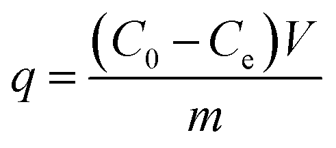 | (1) |
Synthesis of carbon materials from crude liquid phase (CLP)
The dark brown crude liquid product (CLP) from the hydrothermal process was collected and dried at 80 °C overnight. 1.0 g of CLP was mixed with 25 mL 2.4% w/v KOH and stirred for 30 minutes. Afterwards, the mixture was dried at 80 °C for 8 hours, and then pyrolyzed under N2 atmosphere at 800 °C for 3 hours. The pyrolyzed product was washed with 0.1 M HCl and DI water several times until pH 7 was reached, followed by drying at 80 °C for 8 hours. The result was labeled with CLP + KOH-800.Fabrication of carbon-based supercapacitor and electrochemical measurements
The electrochemical properties of CLP + KOH-800 were tested in a symmetric configuration using free-standing carbon electrodes and 6 M KOH as electrolyte. The free-standing carbon electrodes were manufactured by mixing 90 wt% of CLP + KOH-800 with 5 wt% of Carbon black Super P® conductive (99+% – metals basis, Alfa Aesar) and 6 wt% of PTFE (polytetrafluoroethylene preparation diluted 10 times with water from a commercial PTFE – 60 wt% dispersion in H2O, Sigma-Aldrich) in absolute ethanol. Ethanol was fully evaporated from the paste at 110 °C and a few drops of ethanol were added to form compact free-standing electrodes. The electrodes were progressively calendered in an electric 2-rolls mill, until a homogeneous film of 100 μm thickness was obtained. The electrodes were punched in disks of 7 mm diameter and dried at 200 °C overnight. The density of the electrodes was calculated using the following equation:
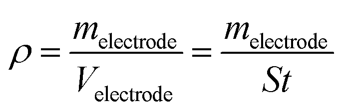 | (2) |
:carbon precursor used in this experiment.
The symmetric supercapacitor was built in a Swagelok T-cell, by sandwiching the two carbon electrodes (with a weight difference <10%) between two stainless-steel current collectors (Hasteloy® 276) and separated by a 10 mm disc glass fiber separator (Whattman, 1 mm thickness). Prior to the assembly, the two carbon electrodes were wetted with the electrolyte. The polarization of both electrodes could be observed by adding a reference electrode (calomel electrode, Hg2Cl2, in saturated KCl solution) in the T-cell (see Fig. S1 in ESI†). The voltage window of the cell was determined by performing CVs at 5 mV s−1 on the T-cells without carbon electrodes. The corrosion current was only observed beyond 1.3 V and 1.2 V was thus taken as voltage window (see Fig S2 in ESI†). For the measurements, the T-cell was connected to a VSP Biologic potentiostat and a series of 500 galvanostatic cycles were run at 5 A g−1 prior to analysis in order to improve the electrolyte access to the micropores of the material. Cyclic-voltammograms (CV) were recorded at various scan rates (5 mV s−1 to 2 V s−1), galvanostatic charge discharge (GCD) at different current densities (0.1 to 130 A g−1) and electrochemical impedance spectroscopy (EIS) between 200 kHz and 10 mHz with a signal amplitude of 10 mV. The specific capacitances (F g−1 and F cm−3) of a single electrode were calculated from the CVs, GCDs and EIS using the equations in ESI.†
Results and discussion
The character of hydrothermal carbonization products (both solid and liquid)
The hydrothermal carbonization of water hyacinth at 180 °C for 24 hours provided both solid and liquid products. The solid phase (WHHTC) appeared dark brown and had approximately 46% ± 3 wt% yield relative to the initial dried water hyacinth precursor. The liquid product was a dark brown solution. This fraction was dried and weighed in order to calculate the yield, which for the crude liquid phase product (CLP) was found to be 17% ± 2 wt% with respect to the dried WH precursor. The CLP was further employed as a carbon precursor for the production of supercapacitors. The overview of our facile synthesis is shown in Scheme 1.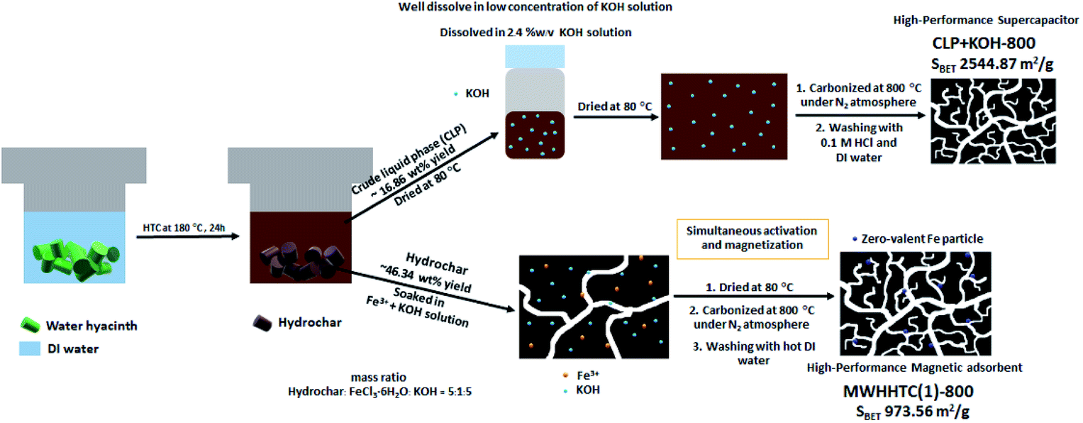 | ||
| Scheme 1 The preparation steps of magnetic adsorbent (MWHHTC(1)-800) and carbon-based supercapacitor (CLP + KOH-800) using water hyacinth as a carbon precursor. | ||
The surface chemical functionality and elemental content of WHHTC hydrochar were investigated by XPS. The results in Table S1† suggests that even before simultaneous magnetization and activation, WHHTC had rather satisfactory carbon (65.80 wt%) and oxygen (27.63 wt%) contents. Despite the rich oxygenated functional groups in WHHTC, it had a relatively poor specific surface (7.35 m2 g−1) and very small porosity (0.0440 cm3 g−1) as shown in Table S3,† which is inadequate for an adsorbent. Therefore, the WHHTC was further activated to improve its porosity and adsorption performance. Moreover, this further activation was simply coupled with in situ magnetization to provide the adsorbent not only higher porosity but also magnetic properties.
Despite the high yield (20–50 wt%), the extraction of crude liquid from lignocellulosic biomass has usually involved toxic organic solvents,27,28 an alkaline catalyst20,21,27 or rather high temperatures (>250 °C).27–29 Notably, in this current study, HTC was performed at a relatively low temperature (180 °C) with only water as the medium. This unusual choice can reduce energy consumption and the complexity of the system.
The thermal behavior of CLP was studied in detail over the temperature range 50–1000 °C (ramp rate = 10 °C min−1) under N2 atmosphere by TGA. According to the thermogram in Fig. S3,† 48.30% of the weight remained even at 1000 °C, indicating outstanding thermal stability of the CLP. The thermogram of CLP exhibits 32.4 wt% loss around 200–700 °C, corresponding to decomposition of the cross-links. Above 700 °C, there is a minor weight loss by 19.3 wt% from decomposition of lignin.30 Apart from the excellent thermal stability, this lignin content in CLP also enables solution-consisted procedures31 making the further preparation of functional CPL-based materials more facile, low-cost and scalable in comparison to the use of solid precursors.
The chemical functionality of CLP was investigated using XPS (Table S1†) and the major elements in CLP were carbon, oxygen and nitrogen at 60.82 wt%, 24.60 wt% and 4.73 wt%, respectively. Hence, CLP from green HTC of water hyacinth had a high proportion of carbon (mainly sp2 carbon (43.3%) and C–O (14.0%)) (Table S2†) giving it good potential for use in synthesis of functional carbon materials.
Magnetic carbon materials as an adsorbent
On preparing magnetic carbon materials, we employed 500 or 800 °C to study effects of this choice on magnetization degree and porosity properties of the resulting carbons. It is clear that both carbonization temperatures (500 °C and 800 °C) and KOH weight ratio (biochar (WHHTC):KOH = 1:1 and 1:0.2) had no effects on the magnetic properties, as observed by the tiny differences in magnetizations shown in Table 1 (all in the small range 4–6 emu g−1). Nonetheless, both factors significantly influenced porosity (Table 1). Increasing the KOH proportion or carbonization temperature led to higher specific surface, and total pore and mesopore volumes (Table 1).
| Materials | Magnetization (emu g−1) | Specific surface area (m2 g−1) | Total pore volume (cm3 g−1) | Mesopore fraction (%) | qt=24 h on MB (mg g−1) |
|---|---|---|---|---|---|
| MWHHTC(0.2)-500 | 6.00 | 271.12 | 0.1825 | 60.33 | 16.46 |
| MWHHTC(0.2)-800 | 4.81 | 677.66 | 0.4348 | 56.28 | 184.24 |
| MWHHTC(1)-500 | 6.00 | 398.14 | 0.2296 | 50.57 | 10.60 |
| MWHHTC(1)-800 | 4.11 | 973.56 | 1.5253 | 87.89 | 535.31 |
| WHHTC(1)-800 | 0 | 1070.27 | 0.5327 | 80.21 | — |
| MWHHTC(0)-800 | 10.23 | 291.17 | 0.1945 | 68.23 | — |
To study the role of iron and KOH on the magnetic properties in detailed, the control experiments were performed using 2 different conditions: (1) hydrochar + FeCl3·6H2O (MWHHTC(0)-800) and (2) hydrochar + KOH (WHHTC(1)-800) by using the same carbonisation temperature at 800 °C. The VSM measurements show that the MWHHTC(0)-800 possessed magnetism properties (10.23 emu g−1) but the sample has low surface area (291.17 cm3 g−1) as shown in Table 1. In contrast, the WHHTC(1)-800 has a high surface area (1070.27 cm3 g−1) but shows no magnetic property (Table 1). The magnetization value of MWHHTC(0)-800 is in the same range as in the other two samples carbonized at the same temperature of 800 °C (MWHHTC(0.2)-800, and MWHHTC(1)-800 with the value of about 4–10 emu g−1). This might be because the Fe species contained in those samples are in the same zero-valent form. The existence of zero-valent iron particles even without KOH activation can be explained by the reduction of Fe3+ ions with the carbon matrix at temperature >700 °C, which is in accordance with the previous studies.32,33 As evidenced by the high surface area of WHHTC(1)-800, this observation indicates that KOH is responsible for the generation of high surface area and pore volume when the activation at 800 °C was used, while iron contributed to the magnetic properties of the composites.
MWHHTC(1)-800 was selected for further characterization and adsorption studies, having both largest surface area and pore volume among the cases tested. The magnetization of 4.11 emu g−1 for MWHHTC(1)-800 is comparable to other porous carbon-based materials reported earlier, such as 3.679 emu g−1 for Fe3C/Fe/C magnetic hierarchical porous carbon34 and 3.83 emu g−1 for magnetic chitosan/poly(vinyl alcohol) hydrogel beads.35 These magnetization values are sufficient to make MWHHTC(1)-800 easily separable from an aqueous suspension with an external magnet (Fig. 3b).
Physicochemical properties, including surface area and pore texture of MWHHTC(1)-800, were studied in detail by various techniques. Fig. 1a shows the N2 isotherm of MWHHTC(1)-800, which clearly is of type IV with an obvious hysteresis loop. This indicates that the material contained mesopores, which is further confirmed from the narrow pore size distribution (PSD) in the range ∼1.5–5.0 nm (Fig. 1b).
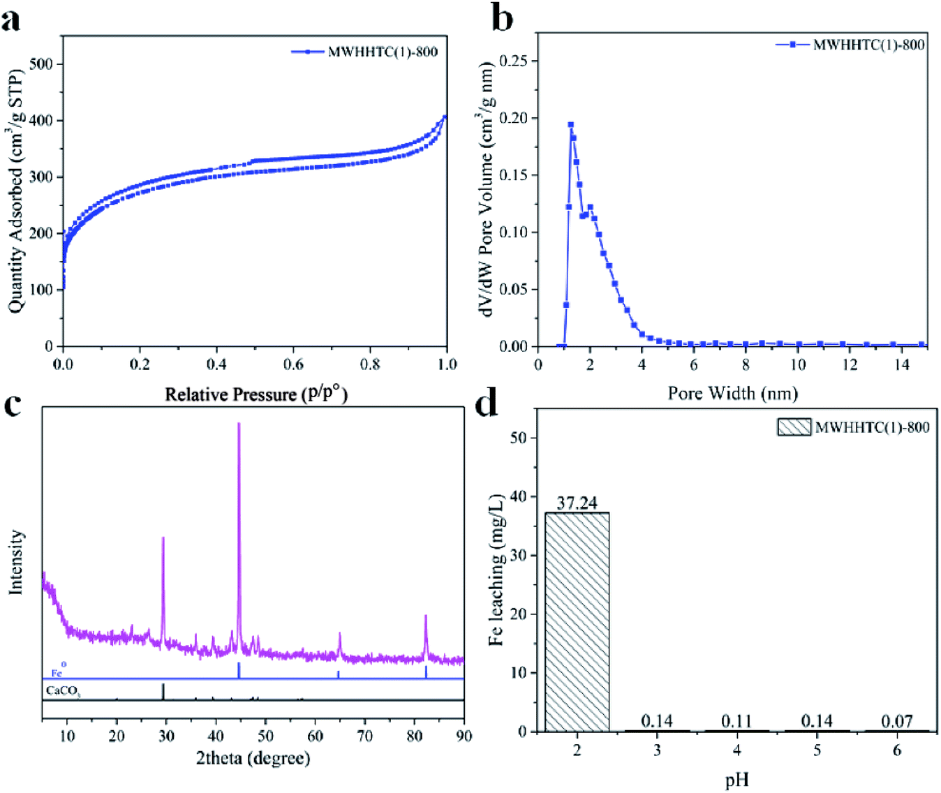 | ||
| Fig. 1 (a) N2 sorption–desorption isotherm, (b) pore size distribution calculated by DFT, (c) XRD pattern, and (d) leached iron concentrations at various pHs, for MWHHTC(1)-800. | ||
Furthermore, MWHHTC(1)-800 possessed high specific surface and large porosity, 973 m2 g−1 and 0.62 cm3 g−1 respectively. The material also had high mesoporosity, 85% of the total pore volume. This large fraction of mesopores not only improves adsorption rate but also enables adsorption of large molecules,36 such as the adsorbates in this study (MB, MO and TC).
To investigate the changes in elemental composition and functionality both qualitatively and quantitatively, XPS measurements were carried out on both non-magnetic hydrochar (WHHTC) and the selected magnetic material (MWHHTC(1)-800). The C 1s XPS spectra of both WHHTC (Fig. S4a†) and MWHHTC(1)-800 (Fig. S4b†) reveal sp2 carbon as the major peak, with 284.6 eV binding energy (BE).37 The gained sp2 carbon content in MWHHTC(1)-800 was clear from those spectra. The C![[double bond, length as m-dash]](https://www.rsc.org/images/entities/char_e001.gif) C functional group in MWHHTC(1)-800 was significantly increased by carbonization and magnetization of relative to initial non-magnetic biochar (WHHTC), from 43.3% to 65.5%, in accordance with the decrease in oxygen content (Table S1†). The peaks at BE 286.0 and 286.8 eV correspond to C–O and C–O–C bonds,38 respectively. The peaks at 288.1 and 289.4 eV confirm the presence of CO and O–CO groups.39 The increased content of CC (sp2) and decreased intensity of oxygen functionalities in MWHHTC(1)-800 indicate that simultaneous magnetization and activation at 800 °C not only improved the porosity but also changed the chemical nature of the carbon product. Moreover, the absence of Fe signal in the wide scan might be caused by the embedding of iron particles deep in the carbon matrix, so they could not be detected by XPS.
C functional group in MWHHTC(1)-800 was significantly increased by carbonization and magnetization of relative to initial non-magnetic biochar (WHHTC), from 43.3% to 65.5%, in accordance with the decrease in oxygen content (Table S1†). The peaks at BE 286.0 and 286.8 eV correspond to C–O and C–O–C bonds,38 respectively. The peaks at 288.1 and 289.4 eV confirm the presence of CO and O–CO groups.39 The increased content of CC (sp2) and decreased intensity of oxygen functionalities in MWHHTC(1)-800 indicate that simultaneous magnetization and activation at 800 °C not only improved the porosity but also changed the chemical nature of the carbon product. Moreover, the absence of Fe signal in the wide scan might be caused by the embedding of iron particles deep in the carbon matrix, so they could not be detected by XPS.
Iron occupancy and iron particles in MWHHTC(1)-800 magnetic carbon material were characterized by XRD, TEM and SEM-EDX techniques, as shown in Fig. 1c and 2a–f, respectively. X-ray diffraction pattern of MWHHTC(1)-800 in Fig. 1c shows peaks at 2θ of 44°, 65° and 82°, corresponding to (110), (200) and (211) planes of zero-valent iron (ICDD 00-001-1262). The existence of the zero-valent iron particles provided the magnetic carbon composite with the ferromagnetic properties.40
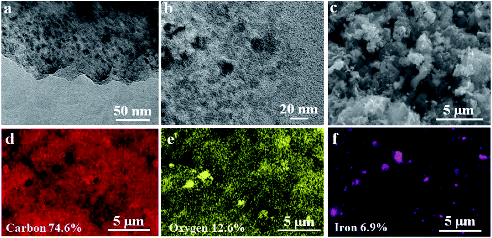 | ||
| Fig. 2 (a) and (b) TEM images, (c) SEM image, and (d)–(f) EDX mappings of MWHHTC(1)-800. | ||
Furthermore, iron specie in this study is metallic iron or zero-valent iron confirmed by XRD pattern in Fig. 1c. So the materials has a ferromagnetic property. Furthermore, the diffraction pattern also indicates a small amount of calcium carbonate residue (ICDD 01-072-1937), which corresponds to the small calcium content detected by XPS.
The formation of metallic iron starts with Fe(OH)3 from the reaction between FeCl3 and KOH. At ∼400 °C, it was converted into Fe2O3 and subsequently transformed into magnetite (Fe3O4). Above 700 °C, magnetite was reduced to zero-valent iron particles.32 During the magnetization process, KOH also played a role as an activating agent forming K2CO3 and K2O species, which could react with carbon in the materials above 700 °C, increasing porosity.32 In this study, the material was prepared by carbonization under N2 atmosphere at 800 °C to accomplish activation and also to obtain magnetic properties. Our method combined magnetization and activation in a single step, without further post-formation of magnetic particles after activation. TEM images in Fig. 2a and b confirm the presence of iron particles (3–24 nm) embedded uniformly throughout the material, which is in accordance with the SEM-EDX results in Fig. 2f. The SEM-EDX technique also reveals the proportions of carbon, oxygen and iron as 74.6 wt%, 12.6 wt% and 6.9 wt%, respectively.
It is noticeable that the synthesis of magnetic carbon composite in this work involved no multi-steps, for example the formation of magnetic ion phase either before or after the incorporation of such magnetic iron species into the adsorbents. This could certainly reduce time-consumption and extra chemicals.
Although few publications have reported on Fe leaching from iron-based magnetic composites,41,42 the stability of iron particles in composite adsorbents against leaching over a wide pH range is important for eventual practical applications. MWHHTC(1)-800 was tested at various levels of pH (2.05–6.30) for 24 hours. The results in Fig. 1d indicate that MWHHTC(1)-800 had good magnetic stability over a wide pH range from acidic (pH 3.05) to neutral (pH 6.30), with negligible release of iron from the composite (<0.15 mg L−1). In particular, at the pH of DI water (pH 6.30), only 0.07 mg L−1 of Fe ions was released. However, the Fe ion concentration became higher in acidic conditions (pH 2.05). Despite some iron discharge in strongly acidic conditions, the material had outstanding resistance to leaching compared with prior studies13,41,42 that assessed pH 3.0. This might be a consequence of entrapping the iron particles by the carbon matrix, and matches the absence of iron signal in XPS, as well as entrapped iron particles seen in TEM images. It is worth mentioning that the stability of MWHHTC(1)-800 over a wide pH range facilitates its practical application as superior adsorbent.
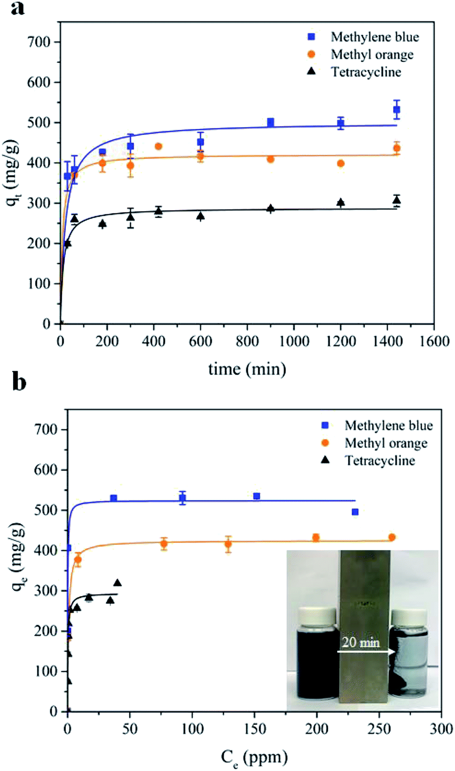 | ||
| Fig. 3 (a) Adsorption kinetics, and (b) adsorption isotherms of MB, MO and TC adsorption by MWHHTC(1)-800. | ||
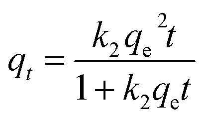
Furthermore, after complete adsorption, a magnet took 20 minutes to attract most of the adsorbent particles. In order to investigate the kinetics of adsorption in detail, the experimental data were fitted with a pseudo second order model as shown in eqn (3)
 | (3) |
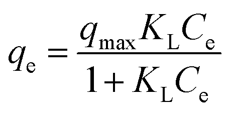
Furthermore, equilibrium adsorption isotherms were determined experimentally. The isotherms in Fig. 3b show that the MWHHTC(1)-800 had high adsorption capacity of MB, MO and TC. The maximum capacities were estimated by fitting the Langmuir isotherm model shown in eqn (4)
 | (4) |
Carbon-based supercapacitor prepared from the crude liquid phase (CLP)
:KOH = 1:0.6 by weight), relative to other reported studies,7,50 was mixed directly into CLP solution that was further pyrolyzed, to enhance porosity without a pretreatment step. It is worth noting that the activation reported here employed much lower KOH amount (1:0.6 wt% of dried liquid product: KOH) in comparison to conventional activation with solid biomass (≥1:1 wt%) and ensured homogeneous mixing of KOH during the activation.Carbon-based supercapacitor prepared with KOH activated CLP had an extremely large BET specific surface area of 2365 ± 163 m2 g−1 and a large pore volume of 1.29 ± 0.15 cm3 g−1. The sample preparation was carried out in triplicate to confirm reproducibility of the preparation protocol. Due to uniformity of the mix with KOH in the activation step, surface area and pore volume were similar in all replicates along with pore texture, as indicated by the small standard deviations. Furthermore, the N2 sorption–desorption isotherms for all replicates were of mixed type I and IV, in the IUPAC classification of isotherms, indicating micropores or small mesopores that are suitable for electrochemical applications due to high diffusivity of the electrolyte.20 One isotherm from the replicates is shown in Fig. 4a.
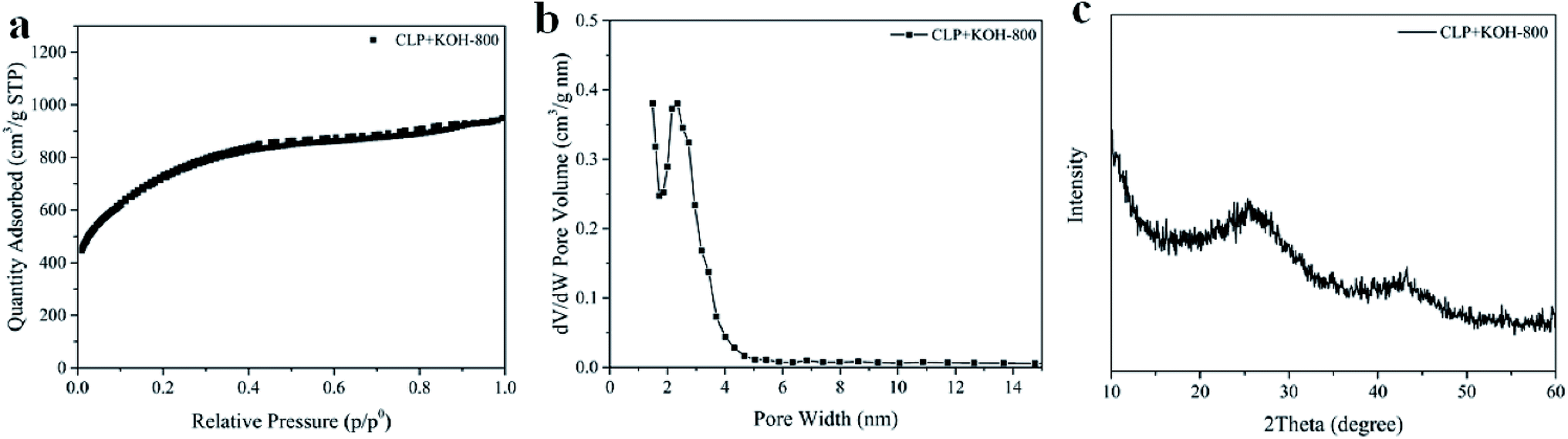 | ||
| Fig. 4 (a) N2 sorption–desorption isotherm, (b) pore size distribution calculated by DFT, and (c) XRD pattern of CLP + KOH-800. | ||
The existing of macroporosity in CLP + KOH-800 was confirmed by SEM images in Fig S6.† The results clearly show that the material contains continuous connected macropores with diameter in the range of 0.1–1 μm (Fig. S6†). Such interconnected macropore morphology is believed to be generated from the melting and reorganization of the carbon precursors upon the carbonization, as described in the previous work.51 The interconnected structure might boost the facile electrolyte diffusion throughout the material.51,52
Chemical functionality and elemental composition of CLP + KOH-800 were investigated by XPS technique and compared to those of pristine CLP (Tables S1 and S2†).
The activation at 800 °C increased the carbon content of CLP + KOH-800 from 60.82 wt% to 78.73 wt%, while the oxygen content dropped to 15.05 wt%. Moreover, sp2 carbon content significantly increased from 43.3 wt% to 64.9 wt%, so abundant π aromatic components were present in the activated sample. Evidence of sp2 carbon is also found in the XRD pattern in Fig. 4c.
The XRD result shows two broad diffraction peaks at 2θ = 26° and 44°, corresponding to (002) and (100) planes in turbostratic carbons. The low intensity broad diffraction peaks suggest a low degree of graphitization in the CLP + KOH-800 material, in comparison to pure graphite. Raman spectrum of CLP + KOH-800 shows two bands at 1345 cm−1 and 1595 cm−1, representing D and G bands, respectively. The ratio of D and G band intensity (ID/IG) of the CLP + KOH-800 is 1.33, indicating that the sample contains the turbostratic nature and structural defects (Fig. S7†).53–55 Despite the low degree of graphitization according to the XRD and Raman results, XPS results confirm a large content of sp2 character in π aromatic form. The presence of such sp2 in π aromatic system could enhance electric conductivity32 which is desired in applications to supercapacitors.
The CVs at various scan rates, shown on Fig. 5a, reveal the super-capacitive nature of CLP + KOH-800 by showing an important capacitive current characterized by a rectangular CV shape. However, the CVs reveal also two important side phenomena occurring during charging and discharging. The first, related to the important current peak observed at low scan rate (5 and 10 mV s−1), is attributed to carbon corrosion/oxidation probably due to the presence of reactive functional groups or unreacted oxygen radicals.56,57 This process is irreversible due to the absence of an observable reduction peak during the discharge cycle. The second phenomenon, called pseudo-capacitance, is characterized by the current bumps at low over potentials during the charging and the constant negative current slopes during the discharge. This could be related to reversible faradaic reactions58 which would either involve the ad/desorption of OH− ions on certain electro-active oxygen groups or hydrogen electro-sorption on the carbon framework.57 However, more insight into the charging mechanisms would be needed to provide definitive answers.
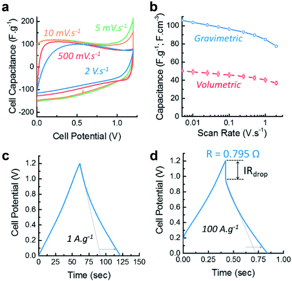 | ||
| Fig. 5 (a) Cyclovoltammograms (CV) of the symmetric cell at various scan rates; (b) rate capability of the device extracted from the CV curves and corresponding error bars due to the incertitudes on the electrode density measurement; (c) and (d) galvanostatic charge discharge curves at 1 A g−1 and 100 A g−1 and the corresponding IRdrop measurement. | ||
In order to assess the performance of the materials at different rates, the capability of the material was calculated from the CVs and shown on Fig. 5b. Both gravimetric and volumetric performances reveal that the material exhibits good rate capability, maintaining 80% of its capacitance at 2 V s−1 and 80 F g−1 at 100 A g−1 as determined by GCDs (see Fig. S8 in ESI†). Combined with a maximum capacitance of 100 F g−1 (or 50 F cm−3) at 5 mV s−1, these features place this material in the range of commercially available supercapacitive carbons in term of energy density.
The galvanostatic charge/discharge also confirm the supercapacitive and pseudo-capacitive behaviour of CLP + KOH-800 by exhibiting a nearly triangular shape at 1 A g−1 and 100 A g−1 (Fig. 5c and d). The increase in charge and discharge time due to the faradaic charge transfer is indicated by the dotted arrow which compare the performances with an “ideal” double layer supercapacitor. Additionally, the small IRdrop in the GCD profiles indicate good electrical conductivity and low cell resistance of 0.795 Ω.
EIS was measured to provide more insight into the charging kinetics of both electrodes before and after the electrodes were cycled to test the stability of the device. The Nyquist plot (Fig. 6a) reveals the presence of a semicircle at high frequency (above 100 Hz), representing the charge transfer resistance Rct of the faradaic processes occurring during charging and discharging. This resistance could either be related to the electrode-current collector contact resistance or the pseudocapacitive phenomenon. The slight increase of Rct upon cycling indicates that the carbon oxidation does not hinder the electrical contact or the pseudo-capacitive mechanisms.
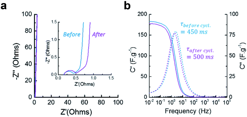 | ||
| Fig. 6 (a) Nyquist plot showing the capacitive and resistive regions and (b) Bode plot showing the real and imaginary capacitance of the material before and after 10000 cycles of galvanostatic charge/discharge. | ||
Between 100 Hz and 100 mHz, the resistive regime shifts into a capacitive regime where the increase in capacitance is limited by diffusion (restricted-diffusion regime), (see Fig. 6b). This indicate that the electrical double layer is not able to form freely from the electrode surface towards the bulk of the electrolyte since it is confined by the mesoporosity of the electrode (pores up to 50 nm). This phenomenon is observed in most supercapacitive porous carbons. When the frequency passes below 100 mHz, the material becomes fully capacitive and the ions are able to penetrate inside the micropores, creating a vertical line on the Nyquist plot. The relaxation time characterizes the shifting frequency characteristic of the material. CLP + KOH-800 is typically in the range of microporous endohedral carbons, which usually exhibit slower relaxation times than porous carbons with exohedral porosity such as certain graphene- or CNT-based architectures, providing them with rapid kinetics (τrelax below 100 ms). Here also, it is observed that the ionic diffusion within the mesopores of the materials is not drastically changed upon cycling and the maximum capacitance obtained by EIS is also comparable. However, a slight increase of the relaxation time can be attributed to the oxidation of the pores surface, which might slow down ions movements through the porous structure. By calculating the cyclability from the GCD curves (Fig. 7a), a retention of 92% after 10000 cycles is acceptable and could be increased by reducing slightly the voltage window or choosing a less corrosive electrolyte.
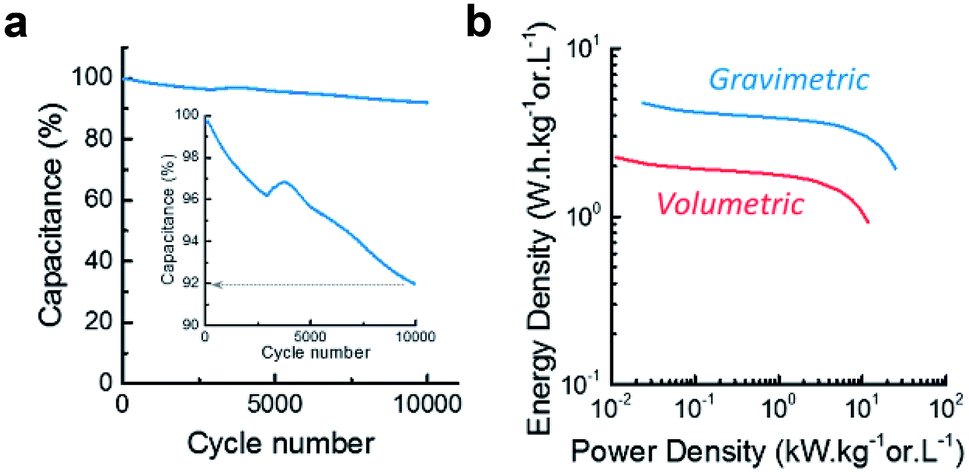 | ||
| Fig. 7 (a) Cyclability over 10000 cycles at 10 A g−1 and (b) Ragone plot. | ||
Finally, the Ragone plot (Fig. 7b) illustrates both the energy and power density of the material, providing an overview of the materials performances. Despite its relatively low micropore volume and large average pore size, CLP + KOH-800 already exhibits electrochemical gravimetric energy density comparable with commercially available carbons (∼5 W h kg−1) and good power density (∼30 kW kg−1) which could be explained by the hierarchical porous structure and the abundance of mesopores. Thanks to the free-standing electrode configuration, the volumetric performances are enhanced (∼2 W h L−1 and ∼10 kW L−1) compared to electrodes manufactured by coated carbon paste on metal foils, while keeping the manufacturing process simple and low-toxicity. These are promising results, knowing that the performances of this material can easily be improved by modifying the microporous structure via an improvement of the synthesis process more adapted to this type of bio-resource.
Conclusions
Magnetic carbon composite adsorbents and carbon-based supercapacitor electrode with excellent performance were successfully prepared from solid and liquid products, respectively in a sustainable way, from low-temperature HTC of water hyacinth. The as-prepared adsorbent shows superior adsorption efficiency towards representative toxic organic compounds in term of both kinetics and adsorption capacity at the equilibrium and also retained good magnetic properties even after use in adsorption. This is due to the presence of high specific surface area and large mesoporosity of the magnetic carbon composite. Furthermore, the good-performance supercapacitor electrode with extremely high surface area can facilely be prepared with the liquid product by employing relatively low amount of KOH. The liquid-derived carbon electrode had high specific capacitance and good capacitance retention, confirming good electrochemical performance. This work demonstrated a simple way to produce functional carbon materials and the use of both solid and liquid HTC products from embarrassing water hyacinth via a more environmentally friendly method. Developing such high value-added carbon-based materials with zero-waste production can facilitate solutions to environmental and energy issues.Conflicts of interest
There are no conflicts to declare.Acknowledgements
This work received financial support from Thailand Research Fund (TRF) (grant no. RDG62W0001) and Newton Fund (grant no. 413673062) under Newton Fund – Thailand Research Fund Institutional Links 2018/19 program (British Council). A. Saning would like to thank Science Achievement Scholarship of Thailand (SAST) for the scholarship. The authors acknowledge Center of Excellence for Innovation in Chemistry, (PERCH-CIC) and Center of Excellence in Nanotechnology for Energy (CENE) at Prince of Songkla University for partial support. We thank Dr Seppo Karrila for assistance with manuscript preparation.References
- V. Guna, M. Ilangovan, M. G. A. Prasad and N. Reddy, ACS Sustainable Chem. Eng., 2017, 5, 4478–4490 CrossRef CAS
.
- T. F. Rakotoarisoa, T. Richter, H. Rakotondramanana and J. Mantilla-Contreras, Econ. Bot., 2016, 70, 365–379 CrossRef
- R. Sindhu, P. Binod, A. Pandey, A. Madhavan, J. A. Alphonsa, N. Vivek, E. Gnansounou, E. Castro and V. Faraco, Bioresour. Technol., 2017, 230, 152–162 CrossRef PubMed
- K. Wu, B. Gao, J. Su, X. Peng, X. Zhang, J. Fu, S. Peng and P. K. Chu, RSC Adv., 2016, 6, 29996–30003 RSC
- Y. Ding, Y. Liu, S. Liu, Z. Li, X. Tan, X. Huang, G. Zeng, Y. Zhou, B. Zheng and X. Cai, RSC Adv., 2016, 6, 5223–5232 RSC
- F. Zhang, X. Wang, D. X. Yin, B. Peng, C. Y. Tan, Y. G. Liu, X. F. Tan and S. X. Wu, J. Environ. Manage., 2015, 153, 68–73 CrossRef CAS PubMed
- K. W. Zheng, Y. Y. Li, M. Zhu, X. Yu, M. Y. Zhang, L. Shi and J. Cheng, J. Power Sources, 2017, 366, 270–277 CrossRef CAS
- G. Zeng, B. L. Zhou, L. C. Yi, H. Li, X. Hu and Y. Li, Sustainable Energy Fuels, 2018, 2, 855–861 RSC
- M. A. Rahman, Waste Manag., 2018, 80, 310–318 CrossRef CAS PubMed
- B. Zhang, Z. P. Zhong, T. Li, Z. Y. Xue and R. Ruan, J. Anal. Appl. Pyrolysis, 2018, 132, 143–150 CrossRef CAS
- A. Jain, R. Balasubramanian and M. P. Srinivasan, Chem. Eng. J., 2016, 283, 789–805 CrossRef CAS
- M.-M. Titirici, R. J. White, C. Falco and M. Sevilla, Energy Environ. Sci., 2012, 5, 6796–6822 RSC
- N. Rattanachueskul, A. Saning, S. Kaowphong, N. Chumha and L. Chuenchom, Bioresour. Technol., 2017, 226, 164–172 CrossRef CAS PubMed
- Z. G. Liu, F. S. Zhang and J. Z. Wu, Fuel, 2010, 89, 510–514 CrossRef CAS
- J. Fang, L. Zhan, Y. S. Ok and B. Gao, J. Ind. Eng. Chem., 2018, 57, 15–21 CrossRef CAS
- K. Nakason, B. Panyapinyopol, V. Kanokkantapong, N. Viriya-empikul, W. Kraithong and P. Pavasant, J. Energy Inst., 2018, 91, 786–796 CrossRef CAS
- S. L. Zhou, X. X. Liu, J. H. Lai, M. Zheng, W. Z. Liu, Q. Xu and D. L. Yin, Chem. Eng. J., 2019, 361, 571–577 CrossRef CAS
- J. Molleti, M. S. Tiwari and G. D. Yadav, Chem. Eng. J., 2018, 334, 2488–2499 CrossRef CAS
- H. Chen, H. H. Ruan, X. L. Lu, J. Fu, T. Langrish and X. Y. Lu, Chem. Eng. J., 2018, 333, 434–442 CrossRef CAS
- L. F. Zhu, F. Shen, R. L. Smith, L. L. Yan, L. Y. Li and X. H. Qi, Chem. Eng. J., 2017, 316, 770–777 CrossRef CAS
- C. X. Bai, L. F. Zhu, F. Shen and X. H. Qi, Bioresour. Technol., 2016, 220, 656–660 CrossRef CAS PubMed
- L. C. Cao, I. K. M. Yu, D. W. Cho, D. Wang, D. C. W. Tsang, S. C. Zhang, S. M. Ding, L. L. Wang and Y. S. Ok, Bioresour. Technol., 2019, 273, 251–258 CrossRef CAS PubMed
- M. Sevilla and A. B. Fuertes, ChemSusChem, 2016, 9, 1880–1888 CrossRef CAS PubMed
- G. A. Ferrero, A. B. Fuertes and M. Sevilla, Sci. Rep., 2015, 5, 16618 CrossRef CAS PubMed
- V. Fierro, V. Torné-Fernández and A. Celzard, Microporous Mesoporous Mater., 2007, 101, 419–431 CrossRef CAS
- G. A. Ferrero, A. B. Fuertes and M. Sevilla, J. Mater. Chem. A, 2015, 3, 2914–2923 RSC
- K. R. Arturi, S. Kucheryayskiy, R. P. Nielsen, M. Maschietti, F. Vogel, S. Bjelic and E. G. Sogaard, J. Supercrit. Fluids, 2019, 143, 211–222 CrossRef CAS
- S. Jadsadajerm, T. Muangthong-on, J. Wannapeera, H. Ohgaki, K. Miura and N. Worasuwannarak, Bioresour. Technol., 2018, 260, 169–176 CrossRef CAS PubMed
- Y. L. Hu, L. Y. Qi, S. H. Feng, A. Bassi and C. Xu, Fuel, 2019, 238, 240–247 CrossRef CAS
- A. Jedrzak, T. Rebis, M. Nowicki, K. Synoradzki, R. Mrowczynski and T. Jesionowski, Appl. Surf. Sci., 2018, 455, 455–464 CrossRef CAS
- Y. Park and J. S. Lee, ACS Appl. Mater. Interfaces, 2017, 9, 6207–6212 CrossRef CAS PubMed
- Y. N. Gong, D. L. Li, C. Z. Luo, Q. Fu and C. X. Pan, Green Chem., 2017, 19, 4132–4140 RSC
- S.-M. Alatalo, E. Daneshvar, N. Kinnunen, A. Meščeriakovas, S. K. Thangaraj, J. Jänis, D. C. W. Tsang, A. Bhatnagar and A. Lähde, Chem. Eng. J., 2019, 373, 821–830 CrossRef CAS
- J. D. Dai, S. J. Tian, Y. H. Jiang, Z. S. Chang, A. T. Xie, R. L. Zhang, C. X. Li and Y. S. Yan, Ind. Eng. Chem. Res., 2018, 57, 3510–3522 CrossRef CAS
- W. B. Wang, H. X. Zhang, J. F. Shen and M. X. Ye, Colloids Surf., A, 2018, 553, 672–680 CrossRef CAS
- R. A. L. Sobrinho, G. R. S. Andrade, L. P. Costa, M. J. B. de Souza, A. de Souza and I. F. Gimenez, J. Hazard. Mater., 2019, 362, 53–61 CrossRef CAS PubMed
- M. M. Titirici, A. Thomas, S. H. Yu, J. O. Muller and M. Antonietti, Chem. Mater., 2007, 19, 4205–4212 CrossRef CAS
- E. Petala, Y. Georgiou, V. Kostas, K. Dimos, M. A. Karakassides, Y. Deligiannakis, C. Aparicio, J. Tucek and R. Zboril, ACS Sustainable Chem. Eng., 2017, 5, 5782–5792 CrossRef CAS
- P. Koilraj and K. Sasaki, Chem. Eng. J., 2017, 317, 1059–1068 CrossRef CAS
- E. Petala, K. Dimos, A. Douvalis, T. Bakas, J. Tucek, R. Zbořil and M. A. Karakassides, J. Hazard. Mater., 2013, 261, 295–306 CrossRef CAS PubMed
- X. Zhu, Y. Liu, G. Luo, F. Qian, S. Zhang and J. Chen, Environ. Sci. Technol., 2014, 48, 5840–5848 CrossRef CAS PubMed
- X. D. Zhu, F. Qian, Y. C. Liu, D. Matera, G. Wu, S. C. Zhang and J. M. Chen, Carbon, 2016, 99, 338–347 CrossRef CAS
- M. J. Ahmed, P. U. Okoye, E. H. Hummadi and B. H. Hameed, Bioresour. Technol., 2019, 278, 159–164 CrossRef CAS PubMed
- F. F. Ma, D. Zhang, T. Huang, N. Zhang and Y. Wang, Chem. Eng. J., 2019, 358, 1065–1073 CrossRef CAS
- H. Ma, J. B. Li, W. W. Liu, M. Miao, B. J. Cheng and S. W. Zhu, Bioresour. Technol., 2015, 190, 13–20 CrossRef CAS PubMed
- M. Ruthiraan, E. C. Abdullah, N. M. Mubarak and M. N. Noraini, J. Environ. Chem. Eng., 2017, 5, 1447–1455 CrossRef CAS
- S. Z. Guo, H. C. Xu, F. Zhang, X. X. Zhu and X. L. Li, Colloids Surf., A, 2018, 546, 244–253 CrossRef CAS
- B. W. Yu, X. L. Zhang, J. R. Xie, R. H. Wu, X. Y. Liu, H. L. Li, F. Chen, H. Yang, Z. Ming and S. T. Yang, Appl. Surf. Sci., 2015, 351, 765–771 CrossRef CAS
- R. K. S. Rathour, J. Bhattacharya and A. Mukherjee, J. Mol. Liq., 2019, 282, 606–616 CrossRef CAS
- H. Zhang, X.-L. Zhou, L.-M. Shao, F. Lü and P.-J. He, ACS Sustainable Chem. Eng., 2019, 7, 3801–3810 CrossRef CAS
- P. Hao, Z. Zhao, J. Tian, H. Li, Y. Sang, G. Yu, H. Cai, H. Liu, C. P. Wong and A. Umar, Nanoscale, 2014, 6, 12120–12129 RSC
- W. Lu, Z. Yuan, C. Xu, J. Ning, Y. Zhong, Z. Zhang and Y. Hu, J. Mater. Chem. A, 2019, 7, 5333–5343 RSC
- E. Hu, J. Ning, B. He, Z. Li, C. Zheng, Y. Zhong, Z. Zhang and Y. Hu, J. Mater. Chem. A, 2017, 5, 2271–2279 RSC
- E. Hu, X.-Y. Yu, F. Chen, Y. Wu, Y. Hu and X. W. David Lou, Adv. Energy Mater., 2018, 8, 1702476 CrossRef
- C. Xu, Z. Lin, D. Zhao, Y. Sun, Y. Zhong, J. Ning, C. Zheng, Z. Zhang and Y. Hu, J. Mater. Sci., 2019, 54, 5412–5423 CrossRef CAS
- M. He, K. Fic, E. Fŗckowiak, P. Novák and E. J. Berg, Energy Environ. Sci., 2016, 9, 623–633 RSC
- F. Beguin and E. Frackowiak, Carbons for Electrochemical Energy Storage and Conversion Systems, CRC Press, 1st edn, 2009 Search PubMed
- Z. Li, D. Zhao, C. Xu, J. Ning, Y. Zhong, Z. Zhang, Y. Wang and Y. Hu, Electrochim. Acta, 2018, 278, 33–41 CrossRef CAS
Footnote |
| † Electronic supplementary information (ESI) available. See DOI: 10.1039/c9ra03873f |
| This journal is © The Royal Society of Chemistry 2019 |