DOI:
10.1039/C6QM00273K
(Review Article)
Mater. Chem. Front., 2017,
1, 414-430
Multi-shelled hollow micro-/nanostructures: promising platforms for lithium-ion batteries
Received
21st October 2016
, Accepted 28th November 2016
First published on 21st December 2016
Abstract
Multi-shelled hollow micro-/nanostructures are of great interest for lithium-ion batteries due to their large surface area, short transport path length and excellent buffering capability. Although great efforts have been made in the design and synthesis of multi-shelled hollow micro-/nanostructures and exploiting their use for lithium-storage techniques, the correlations between their compositional and geometrical properties and their lithium-storage performance haven't been uncovered comprehensively. In this review, we firstly outline the principal parameters that decisively affect the lithium-storage characteristics, and introduce synthetic methodologies for the compositional and geometric manipulation of multi-shelled hollow micro-/nanostructures. Secondly, the recent developments within multi-shelled hollow micro-/nanostructures for lithium-ion batteries are summarized. By adopting these fascinating hollow structures, the capacity, stability and rate capability can be improved simultaneously and substantially. Lastly, the current challenges and future perspectives related to multi-shelled hollow micro-/nanostructures for lithium-ion batteries are further discussed.

Jiangyan Wang
| Jiangyan Wang received her BE from the China University of Mining and Technology, Beijing (2010) and PhD from the Institute of Process Engineering, Chinese Academy of Sciences (2016). She is currently a postdoctoral scholar at Stanford University. Her current research interests are focused on the design and synthesis of micro-/nanostructured functional inorganic materials and nanomaterials for energy conversion and storage, such as lithium ion batteries and supercapacitors. |

Hongjie Tang
| Hongjie Tang received his BE from the China University of Geosciences, Beijing (2009) and PhD from the Institute of Process Engineering, Chinese Academy of Sciences (2015). He is currently a postdoctoral scholar at the University of California, Riverside. His current research interests are focused on the design and synthesis of multifunctional composite materials for energy and environmental applications. |

Huan Wang
| Huan Wang received his BE degree from Hebei University of Science & Technology (2013). He is currently studying for his ME degree under the supervision of Prof. Ranbo Yu from the University of Science & Technology Beijing and Prof. Dan Wang from the Institute of Process Engineering, Chinese Academy of Science. His current research interests are focused on the design and synthesis of micro/nanostructured functional inorganic materials for energy conversion and storage. |

Ranbo Yu
| Ranbo Yu received her BS and MS at Jilin University (1994 and 1997) and PhD at Yamanashi University (2002). As a postdoctoral researcher, she worked in Kyoto University (JSPS fellow) and the University of Houston in 2002 and 2003. She started her career in 2004 at the Department of Physical Chemistry, School of Metallurgical and Ecological Engineering, University of Science and Technology, Beijing, and began her current position as a full professor in 2010. Her research interests include inorganic materials chemistry and surface chemistry, with a focus on the development of micro-/nanostructured functional inorganic materials and their applications in energy conversion and storage. |

Dan Wang
| Dan Wang received his BS and MS at Jilin University (1994 and 1997) and PhD at Yamanashi University (2001). He received an award from the Hundred Talents Program of the Chinese Academy of Sciences (2004) and began his current position as a Principal Investigator at the State Key Laboratory of Biochemical Engineering, Institute of Process Engineering, Chinese Academy of Sciences. His research interests include inorganic materials chemistry, surface and colloidal chemistry, hydro-thermal chemistry, sol–gel chemistry and self-assembly processes, with a focus on the design and synthesis of micro-/nanostructured functional inorganic materials and their applications in energy conversion and storage, photocatalysis and sensors. |
1. Introduction
The global energy crisis and environmental pollution have been considered as the two biggest challenges threatening the sustainable development of humanity, which drives scientists and engineers to develop clean, renewable, highly efficient energy conversion and storage systems to replace the traditional fossil fuels (coal, petroleum oil and natural gas).1–5 Compared to other technologies, lithium-ion batteries (LIBs) have drawn great attention due to their light weight, small self-discharge, high energy density, lack of charge memory, and environmental friendliness.6–10 Owing to the great efforts by scientists all over the world in recent decades, lithium-ion batteries have become one of the dominant power sources for portable electronics and are also considered as the most promising power source for hybrid, plug-in hybrid, and electric vehicle applications.11–13 However, with the ever-increasing demands to support newly emerging electronics, advanced communication facilities and so forth, significant efforts still need to be made to develop next-generation LIBs with a larger capacity, higher safety, better stability and higher rate capability.14
As is known, the performance of LIBs mostly depends on the properties of the electrode materials and significant research has been devoted to obtaining more suitable electrode materials to meet the growing need for high-performance batteries. For example, to overcome the capacity limitation of the current electrode materials, alternative electrode materials with higher capacities have been investigated: the theoretical capacity of a Si anode is 10 times higher than that of a commercial graphite anode (4200 vs. 372 mA h g−1),15 while that of a sulphur cathode is almost 5 times higher than a commercial LiCoO2 cathode (1675 vs. 274 mA h g−1).16 Meanwhile, some new Li-storage mechanisms have also been introduced,24 such as alloying/de-alloying for metals (e.g., Si,17 Sn,18 Al19) and their alloys,20 and a reversible conversion mechanism for transition metal oxides (e.g. Fe2O3,21 Co3O4,22 NiO23), which are quite different from the traditional Li insertion/extraction types (graphite anode and most cathode materials).
Despite these great successes, practical use of these electrode materials for LIBs is still largely hindered by their poor capacity retention upon cycling and/or intrinsic low rate capability. While the latter is generally due to an intrinsic low charge/ionic conductivity, the former usually results from large volume changes (e.g., up to 300% for silicon) that lead to easy breakdown of the electrode structure.25 According to previous reports, hollow micro-/nanostructures, especially multi-shelled hollow micro-/nanostructures, that replace solid micro-/nanostructures as LIB electrode materials can effectively circumvent these issues.26–30 Just as the name implies, multi-shelled hollow micro-/nanostructures are micro-/nanometer-scale structures with a hollow interior and multiple (≥3) different sized shells. They can be regarded as a multi-layered structure of several hollow units, similar to an “onion” structure or a “Russian doll” structure.31 As Fig. 1 shows, the advantages of multi-shelled hollow micro-/nanostructures as LIB electrode materials are obvious and are listed as follows:32–35 (1) the larger surface area of the hollow structures enables an increased electrode–electrolyte contact area as well as more surficial Li+ storage sites, resulting in a larger gravimetric capacity; (2) the hollow structures often ensure a reduced effective diffusion distance for charges and ions, leading to a better rate capability; (3) the hollow interior provides additional free volume to alleviate the structural strains associated with repeated Li+-insertion/deinsertion processes, giving rise to a better structural and cycling stability; (4) compared with their single- or double-shelled counterparts, multi-shelled hollow micro-/nanostructures possess a larger volumetric capacity and better structural and electrochemical stabilities, with the different shells supporting each other and the exterior shell protecting the interior shells.
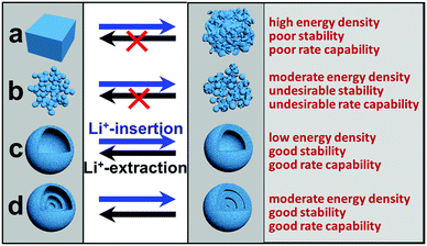 |
| | Fig. 1 Schematic illustration of the structural changes for different structures during Li+ insertion/extraction processes. (a) Solid bulk; (b) nanoparticles; (c) single-shelled hollow structures; (d) multi-shelled hollow structures. | |
Several recent articles have summarized the research progress for hollow micro-/nanostructured materials.9,31,32,36–38 Two of them32,38 discuss briefly the progress made for some specific aspects of multi-shelled hollow spheres and their applications. Most recently, one review33 has given special attention to multi-shelled hollow micro-/nanostructures, and the synthetic methodology applications of multi-shelled hollow micro-/nanostructured materials were reviewed comprehensively. Alternatively, in this review we focus on correlations between the compositional and geometric properties of multi-shelled hollow micro-/nanostructures and their lithium-ion battery performance. Firstly, various compositional and geometric parameters and their effects on the corresponding lithium-ion battery characteristics are well discussed. Then, detailed methodologies and technologies for compositional and geometric manipulation are highlighted. Finally, the lithium-ion battery characteristics of multi-shelled hollow micro-/nanostructures are summarized according to the different Li-storage mechanisms.
2. Principal parameters that determine the LIB characteristics
The key parameters that determine the lithium-ion battery performance of multi-shelled hollow micro-/nanostructures can be catalogued into two types: compositional and geometrical parameters.
2.1 Compositional parameters
The performance of LIBs essentially relies on battery chemistry, which is mostly determined by the composition of the electrode materials. Electrode materials with different elemental compositions have different electronic/ionic conductivities, different lithiation/delithiation potentials, and especially different Li+-storage mechanisms, which affect the amount of stored Li ions and accessible sites, thus resulting in different theoretical capacities39,40 as well as volume change rates and cycling stability, as shown in Table 1 and Fig. 2.
Table 1 Comparison of various electrode materials
| Materials |
C |
TiO2 |
Li4Ti5O12 |
LiCoO2 |
LiMn2O4 |
V2O5 |
Si |
Mn2O3 |
Co3O4 |
| Notes: three types of Li-storage mechanism. Type 1: insertion/extraction mechanism; type 2: alloying/de-alloying mechanism; type 3: conversion-reaction mechanism. |
| Li-storage mechanism type |
1 |
1 |
1 |
1 |
1 |
1 |
2 |
3 |
3 |
| Full lithiated phase |
LiC6 |
LiTiO2 |
Li7Ti5O12 |
LiCoO2 |
LiMn2O4 |
Li3V2O5 |
Li4.4Si |
Mn & Li2O |
Co & Li2O |
| Theoretical specific capacity (mA h g−1) |
372 |
335 |
175 |
274 |
148 |
441 |
4200 |
1008 |
892 |
| Volume expansion (%) |
12 |
4 |
1 |
— |
— |
100 |
420 |
100 |
100 |
| Potential versus Li (V) |
0.05 |
1.7 |
1.6 |
4.2–3.5 |
4.0–4.2 |
3.5–2.0 |
0.4 |
0.5 |
1.0 |
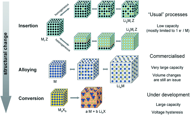 |
| | Fig. 2 A schematic representation of the different reaction mechanisms observed in electrode materials for lithium batteries. Black circles: voids in the crystal structure, blue circles: metal, yellow circles: lithium. Reprinted with permission from ref. 11. Copyright 2009 Royal Society of Chemistry Publishing. | |
The electrode materials for LIBs can perform their Li-storage functions via three types of mechanisms, as shown in Fig. 2:11 (1) an insertion/extraction mechanism. Transition metal oxides and other compounds with a two-dimensional (2D) layered or 3D network structure can reversibly intercalate Li into the lattice (similar to graphite) without destroying the crystal structure, for example V2O5, LiMn2O4, Li4Ti5O12 and TiO2. Electrode materials based on this mechanism are supposed to endow a better cycling, whereas their theoretical capacity is low because less Li ions can be stored in this manner; (2) an alloying/de-alloying mechanism. Elements (A, e.g. Si and Sb) or metals (M, e.g. Sn, Zn and Cd) can form alloys with Li metal (strictly intermetallic compounds, LixA or LixM), which adopt distinct crystal structures and exhibit physical properties different from those of the Li, A, or M. The Li alloying/de-alloying reactions, which usually occur at lower potentials (≥1.0 V vs. Li), contribute to the reversible capacity during Li cycling (e.g., Sn (or Si) + 4.4Li ↔ Li4.4Sn (or Si)). The theoretical capacity for this kind of electrode material is usually very high, yet the structural and cycling stabilities are poor due to the larger volume change rate caused by excess Li ion penetration; (3) conversion reaction mechanism. Redox or “conversion” reactions happen between the electrode material and Li metal, forming Li2O and the corresponding metal or element. Normally, the stable lithium oxide, Li2O, is electrochemically inactive and cannot be decomposed to Li metal and oxygen. However, in the presence of nano-sized transition metal particles, which may or may not be electrochemically generated, it can be decomposed, as exemplified by the now well-known reaction: nano-CoO + 2Li ↔ nano-Co + Li2O. This conversion reaction is a general phenomenon and is applicable to oxides, fluorides, oxyfluorides, sulfides, nitrides, phosphides, etc. The theoretical capacity of electrode materials operating through this mechanism is higher than those of the first kind of materials using an insertion/extraction mechanism, yet lower than the second ones with an alloying/de-alloying mechanism, and the cycling stability is also in between.
2.2 Geometrical parameters
Although the battery capacity is thermodynamically determined by the compositional parameters, the geometrical parameters of multi-shelled hollow micro-/nanostructures, such as the morphology, shell number, inter-shell spacing, shell thickness and grain size, can still regulate the lithium storage behaviour of electrode materials and exert effects on the overall battery performance to some extent.
2.2.1 Effect of morphology.
For practical application, a good slurry processability has been considered a basic requirement for an electrode material and is greatly related to the morphology of the electrode material. Generally, compared to other non-spherical shaped structures, spherical structures have a lower specific area and can help to overcome the surface tension in the slurry, thus benefiting the slurry pasting, resulting in a smoother and more uniform electrode film. Besides, it is believed that spherical structures can easily form a more densely packed array, thus a higher tap density.38 Moreover, during the practical assembly of a lithium-ion battery, calendering is usually adopted to achieve a high tap density, good contact between the different electrode counterparts (including the active materials, conductive materials and binder), as well as a high volumetric capacity.41,42 For spherical micro-/nanostructures, the structural strain and stress distribute evenly during the calendering process, thus guaranteeing good structural (Fig. 3a) and cycling stability. Inversely, the distribution of the structural strain and stress is inhomogeneous for non-spherical micro-/nanostructures, meaning that some parts of the structure (such as sharp corners) have to suffer a much larger strain/stress, which makes the structures unstable and easy to break down (Fig. 3b), and results in a bad contact between the electrode materials and poor cycling stability.
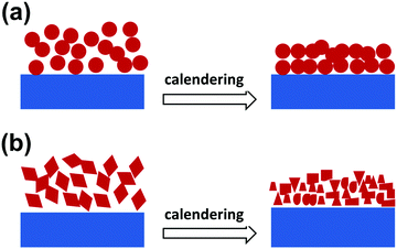 |
| | Fig. 3 Schematic for the structural changes in spherical (a) and non-spherical (b) structures after a calendering process. | |
2.2.2 Effect of the shell number and inter-shell spacing.
The shell number is one of the most important features for multi-shelled hollow structures, which distinguishes them from their single- or double-shelled counterparts and results in their unique chemical/physical properties. Especially, multi-shelled hollow micro-/nanostructures provide a larger volumetric capacity and better structural and electrochemical stabilities. However, the inter-shell spacing as well as the inner cavity-volume-occupying rate (which is defined as the ratio of the inner cavity volume to the overall sphere volume) may decrease along with increase of the shell number, which may have an adverse effect on the lithium-storage properties. As Table 1 shows, each electrode material has a distinct theoretical volume expansion rate (for example, 100% and 420% for Co3O4 and Si, respectively) during lithium insertion. A cavity-volume-occupying rate that is too large is unfavourable for obtaining a high volumetric specific capacity (Fig. 1c), while a much smaller value has a negative effect on the structural stability due to insufficient space for expansion of the electrode material, thus leading to electrode failure and a poor cycling performance. In other words, there must be a compromise between the shell number and inter-shell-spacing, and only an appropriate cavity-volume-occupying rate can guarantee a high volumetric specific capacity as well as good cycling stability (Fig. 1d).43
2.2.3 Effect of the shell thickness and grain size.
In addition, the shell thickness and grain size of multi-shelled hollow micro-/nanostructures also play an important role in influencing their overall lithium-ion storage performance. In most cases, the shells of the hollow structures are composed of small grains and their thickness generally depends on the grain size and amount. Normally, the active surface areas of electrode materials as well as the lithium storage sites increase along with decrease of the grain size. In addition, the diffusion of lithium ions within the electrode material is related to the diffusion coefficient of the lithium ions and their diffusion distance (eqn (1), where t, L, D represent the diffusion time, diffusion length and diffusion coefficient, respectively).44 Since the lithium ion diffusion coefficient is dependent on the composition parameters, as was discussed above, grain size minimization as well as shell thickness minimization become effective ways to decrease the diffusion distance, thus improving the rate capability of electrode materials (Fig. 4).
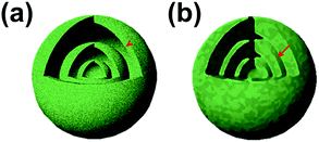 |
| | Fig. 4 Schematic illustration of the diffusion path with different shell thicknesses: (a) thin shell and (b) thick shell. | |
3. Compositional and geometrical manipulation of multi-shelled hollow micro-/nanostructures
Multi-shelled hollow micro/nanostructures, which possess distinct structural features, such as an enlarged surface area, hollow volumetric space and hierarchical shell structures, have been demonstrated to be promising candidates for solving the problematic issues within current lithium technology. In addition, as discussed above, various parameters of the multi-shelled hollow micro-/nanostructures can have an influential effect on the overall lithium-ion storage performance. These characteristics can be well manipulated in terms of both the compositional and geometric counterparts.
Generally, hollow micro/nanostructures can be achieved through two distinct types of synthetic method: templating methods, which use hard or soft materials with a specific morphology as templates to guide the synthesis, and template-free methods, which rely on various building blocks self-assembling into the desired hollow structures. However, the structural complexity of the multi-shelled hollow micro-/nanostructures makes the synthesis more difficult than for single- and double-shelled ones. Although significant improvements have been achieved by scientists for the design and fabrication of multi-shelled hollow micro-/nanostructures during recent years, precise control of their composition and geometric parameters is still a big challenge. In this section, the recent progress in the compositional and geometric manipulation of multi-shelled hollow micro-/nanostructures is summarized in detail.
3.1 Composition manipulation
As discussed above, the compositional components of the multi-shelled hollow micro-/nanostructures can intrinsically determine the lithium ion storage capability of the electrode material. By carefully adjusting the synthesis parameters, single-, dual- and multi-component multi-shelled hollow micro/nanostructures with a special composition have been synthesized for high performance lithium-ion batteries.45
Previously, our group reported a general and facile sequential templating approach for obtaining multi-shelled hollow micro/nanostructures. Carbonaceous saccharide templates were used to adsorb various metal salt precursors and the subsequent heating procedures can remove the templates, and crystallize and oxidize the metal species, resulting in multi-shelled hollow structures (Fig. 5).46,47 Numerous multi-shelled hollow spheres (Fig. 6) of single metal oxides (such as α-Fe2O3, Co3O4, NiO, CuO, and ZnO), binary metal oxides (MFe2O4, M = Zn, Co, Ni, Cd) and also heterogeneous mixed metal oxides (ZnO@ZnO/ZnFe2O4@ZnO/ZnFe2O4) have been successfully prepared using this templating method. When annealed in air, a temperature gradient along the radial direction is formed, meaning that the exterior of the carbonaceous microspheres is more easily combusted into gases and released, reducing the size. In addition, the metal ions within the exterior begin to accumulate, until a certain “threshold” value is reached, and are oxidized into metal oxides, forming a rigid shell. Further heating results in separation of the outer metal oxide shells and inner carbon templates. Following this, the inner templates go through a similar template removal and metal oxide crystallization process, forming more shells inside and eventually the multi-shelled hollow structures are obtained. Besides, the concentration and radial distribution of metal ions can be adjusted by changing the corresponding experimental conditions, such as the metal salt concentration, the solvent, the adsorption temperature and duration, the heating temperature and rate, and so forth, thus controlling the geometric parameters of the multi-shelled hollow structure products.
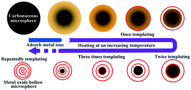 |
| | Fig. 5 Illustration of the sequential templating approach used to obtain multi-shelled hollow metal oxide microspheres. Reprinted with permission from ref. 46. Copyright 2011 John Wiley & Sons. | |
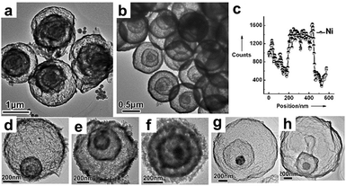 |
| | Fig. 6 TEM images of (a) quadruple-shelled α-Fe2O3 hollow microspheres and (b) quadruple-shelled NiO hollow microspheres; (c) an EDS line scan of triple-shelled NiO hollow microspheres; TEM images of other multi-shelled hollow microspheres, (d) Co3O4, (e) CuO, (f) ZnO, (g) ZnFe2O4 and (h) ZnO@ZnO/ZnFe2O4@ZnO/ZnFe2O4. Reprinted with permission from ref. 46. Copyright 2011 John Wiley & Sons. | |
Zhang et al.48 also developed a similar “penetration–solidification–annealing” strategy for the synthesis of multi-shelled ternary transition metal oxide hollow spheres. The metal ions deeply penetrated into the carbonaceous spheres and the subsequent solidification process was carried out at high temperature with the assistance of a unified polyol system. Finally, the multi-shelled hollow spheres were generated through thermal treatment in air to induce the formation of both interior and outer shells with well crystallized metal oxides. The separation of the “penetration” and “solidification” processes provides versatility for forming various mixed transition metal oxides (e.g. ZnMn2O4, ZnCo2O4 and NiCo2O4) and an adjustable composition by adopting the required precursors.
It is worth noting that carbonaceous microspheres are not necessarily needed and can be replaced by other templates, such as polymer particles. Cho et al.49 reported the synthesis of composition-tunable multi-shelled hollow hybrid metal oxide microspheres using coordination polymer particles (CPPs) as the templates. This methodology involves three straightforward steps: (I) CPP preparation using a precipitation method, (II) a cation exchange reaction for compositional transformation of the CPPs, and (III) calcination of the pre-prepared CPPs, which engenders decomposition of the CPPs and formation of metal oxides (Fig. 7). The mechanism of the formation of the multi-shelled hollow structures is very similar to that using carbonaceous microspheres (CMSs) as templates, as discussed above. Specially, the spherical CPPs (M–MSB–M, M = Zn2+ or Co2+), which are made of a Schiff base and transition metal ions, are mixed with secondary metal ions (M′ = Cu2+, Co2+, or Ni2+) to effect the cation exchange and produce the requisite bimetallic CPPs (M′–MSB–M). Subsequent thermal treatment of the CPPs results in the multi-shelled hollow spheres of hybrid mixed metal oxides. Since CPPs of the general form M′–MSB–M can be prepared using a wide range of metal species (M and M′), this methodology will provide a general strategy for preparing numerous novel composition-customized hybrid metal oxides with unique multi-shelled structures.
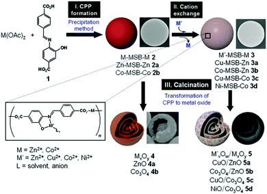 |
| | Fig. 7 Scheme of the preparation of multi-ball-in-ball hybrid metal oxides. Reprinted with permission from ref. 49. Copyright 2011 John Wiley & Sons. | |
The penetration of metal ions could also be carried out simultaneously through the preparation of templates for process simplification. Hong et al.50 reported a one-pot spray pyrolysis process for synthesizing multi-shelled hollow structures with composition-variable single, binary, ternary, quaternary, and quinary systems (Fig. 8). Sucrose was used as the carbon source, which can also be substituted with other organic materials, such as polyethylene glycol, polyvinyl alcohol, glucose, citric acid and so on. The fast drying and decomposition of the sprayed droplets produced micron-sized carbon–metal oxide composite particles with a uniform composition by minimizing the phase separation of each component. Upon heating, the exterior of the carbon–metal oxide composite goes through an immediate combustion of the carbon, whereas the interior of the densely structured particles does not combust because of an insufficient supply of oxygen. The subsequent combustion and contraction of the C–metal oxide core results in single- or multiple-shell-structured metal oxide particles. By selecting different metal salts as the precursors, various components (Ti, Al, Zr, Ce and Y) within the yolk–shell particles can be extremely well-distributed amongst the shells and cores, even in the quinary systems. Besides metal oxides, multi-shelled hollow transition metal sulfides could also be obtained using this method. Sulfidation of the yolk–shell oxide microspheres with H2S gas can result in SnS–MoS2 composite microspheres (Fig. 9 and 10).51,52 Although these methods are of great simplicity, the introduction of additional metal ions or the intrinsic limitations of the spray drying method usually decrease the size uniformity of the multi-shelled hollow products.
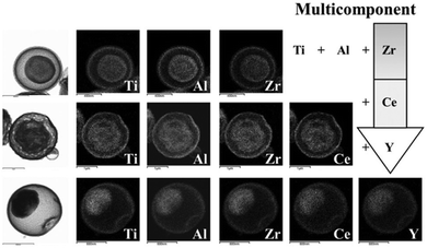 |
| | Fig. 8 Morphologies and dot-mapping results for the products with ternary, quaternary, and quinary systems. Reprinted with permission from ref. 50. Copyright 2013 John Wiley & Sons. | |
 |
| | Fig. 9 Illustration of the formation mechanism for the yolk–shell SnS–MoS2 composite microspheres. Reprinted with permission from ref. 52. Copyright 2015, American Chemical Society. | |
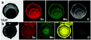 |
| | Fig. 10 Elemental mapping images of yolk–shell (a) SnO2–MoO3 and (b) SnS–MoS2 composite microspheres. Reprinted with permission from ref. 52. Copyright 2015, American Chemical Society. | |
3.2 Geometric manipulation
3.2.1 Morphology manipulation.
The geometric morphology of multi-shelled hollow structures can also have a significant effect on their lithium storage capability, as well as their long-term cycling stability. For example, due to the better stress/strain buffering capability of spherical structures, multi-shelled hollow structures mostly have a spherical morphology. Despite this, there are still some successful examples of constructing non-spherical multi-shelled hollow structures.53,54
Generally, the shape of the hollow product is determined by that of the template. Acapulco Jr. et al.53 have reported the synthesis of multi-shelled bimetallic Ag/Au hollow nanoparticles with different shapes by utilizing differently shaped Au nanoparticles as the cores. As Fig. 11 shows, Ag overlayer coating and subsequent galvanic replacement of the Ag solid coating with Au ions were used to synthesize the bimetallic Ag/Au hollow nanoparticles, with multiple nanoshells obtained by simply repeating the Ag-coating and galvanic replacement. It is noteworthy that the shell thickness and the distance between the core and the shell could be tailored by adjusting the thickness of the Ag overlayer. Specifically, a thicker Ag overlayer coating led to a thicker shell and greater separation between the cores and shells. This was due to the Kirkendall effect as well as epitaxial Au growth on the Ag layer, through which Ag was continuously oxidized from the inner layer, dissolved in the solution, and finally reduced and deposited on the outer Ag layer. Usually, complete replacement of the Ag layer with Au ions is not achievable, and instead results in the formation of an Au/Ag alloy. The central Au cores maintained their original morphology regardless of the total number of replacement reactions. As a result, multi-shelled Au/Ag hollow nanorods or nanospheres were obtained respectively through using a Au nanorod or nanosphere as the core.
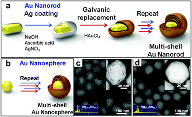 |
| | Fig. 11 (a and b) Schematic illustrations for the synthesis of (a) multi-shell nanorods with a Au core and (b) multi-shell nanospheres with a Au core. (c and d) HAADF-STEM images of (c) nanorod and (d) nanosphere cores with quadruple nanoshells, with the EDS composition analysis in the inset. Reprinted with permission from ref. 53. Copyright 2016, Elsevier. | |
Wang et al.54 reported a facile “pumpkin-carving” strategy for the preparation of hollow single-crystal CoSn(OH)6 nanoboxes with multiple different interiors. Perovskite-type CoSn(OH)6 nanocubes were firstly prepared through fast stoichiometric co-precipitation of Sn2+, Co2+ and OH− in the presence of citrate ions, which served as precursors and their cubic crystalline structures can be inherited to form single crystal nanoboxes. A kinetically-controlled etching process in an alkaline medium followed, to gradually dissolve the CoSn(OH)6 nanocubes. In this process, an insoluble boundary layer of Co(III) species can be readily formed on the surface of the CoSn(OH)6 crystals, which makes the outer surface of the cubes less reactive than the freshly exposed interior and is critical for this unusual hollowing process. With continuous evacuation of the core material across the shells, mesoporous CoSn(OH)6 nanoboxes with well-developed inner cavities were eventually formed without sacrificing the high crystallinity (Fig. 12). More impressively, CoSn(OH)6 hollow architectures with multi-shelled nanoboxes can be readily produced by repeating the deposition process of CoSn(OH)6 layers onto pre-grown CoSn(OH)6 particles (e.g., nanocubes or nanoboxes) and successive alkaline etching.
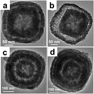 |
| | Fig. 12 TEM images of CoSn(OH)6 nanoboxes with multilevel interiors: (a) double-shelled; (b) double-shelled with a larger inter-shell cavity; (c) triple-shelled; and (d) quadruple-shelled. Reprinted with permission from ref. 54. Copyright 2013, Nature Publishing Group. | |
3.2.2 Shell parameter manipulation.
The characteristic shell parameters of multi-shelled hollow structures, including the shell number, thickness, inter-shell spacing, grain size and induced cavity-volume-occupying rate, endow them with unique physical or chemical properties, which can bring great advantages when they are used as electrode materials for LIBs. Great efforts have been devoted to controlling the various structural parameters via different techniques to optimize their performance in lithium storage applications.55–85 Generally, there are three types of synthetic methods for preparing multi-shelled hollow micro-/nanostructures: hard-template, soft-template and template-free methods. Amongst these, the sequential templating method, which is the most efficient and convenient of the hard-template methods, can provide accurate control of the various shell parameters through fine adjustment of both the precursor-adsorption process and annealing process. As Fig. 13 shows, by controlling the concentration of the precursor solution, the solvent type, the pH value, the solution temperature and the adsorption duration, the concentration and penetration depth of the metal ions within the templates can be well adjusted. Combining this with tuning of a series of annealing parameters used to remove the templates and drive crystallization, such as the heating rate, temperature and atmosphere, acquisition of multi-shelled hollow micro-/nanostructures with the desired shell parameters can be achieved.
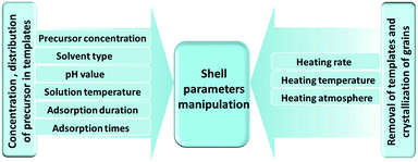 |
| | Fig. 13 Schematic diagram of shell parameter manipulation using a sequential templating method through careful control of the precursor adsorption and annealing processes. | |
Shell number is one of the most apparent features of multi-shelled hollow structures, which distinguishes them from their single- or double-shelled counterparts. Our reported sequential templating approach allows fine control of the shell number of multi-shelled hollow spheres through careful optimization of the synthesis parameters during both the adsorption and annealing processes.46,47 The concentration and penetration depth of the metal ions within the carbonaceous templates are thought to be the key parameters determining the final shell number and they can be well adjusted by controlling the adsorption process. For example, by simply changing the concentration of the iron nitrate solution from 2 mol L−1 to 3 mol L−1 or 5 mol L−1, α-Fe2O3 hollow microspheres with three or four shells were obtained instead of a double-shelled structure. However, due to the larger radii of hydrated cobalt ions ([Co(H2O)6]2+) and thus poor “penetration”, only single-shelled Co3O4 microspheres were obtained even when a high concentration of Co2+ was applied. Nevertheless, on introducing some ethanol into the metal ion solution, the wettability of the carbonaceous templates increased, and also the coordination of aquo groups to the Co2+ was reduced and thus the radii of the hydrated cobalt ions decreased. By utilizing this method and combining it with a higher adsorption temperature, the amount of adsorbed Co2+ ions and their penetration depth within the carbonaceous templates increased, inducing double- and triple-shelled Co3O4 microspheres after removal of the carbon templates. In addition, pre-treatment of the carbonaceous templates with an acid solution can further strengthen the ion penetration, resulting in Co3O4 microspheres with four shells (Fig. 14 and 15). Moreover, the pH value of the precursor solution and the immersion period of the metal ions have also demonstrated an apparent influence on the adsorption amount and depth of the metal ions with carbon templates, and Mn2O3 hollow microspheres with different numbers of shells have been formed (Fig. 16).55 Both the negative charges on the CMSs and the positive charges of the Mn cations become less (the coordination group of the Mn2+ ions changed from [Mn(H2O)6]2+ to [Mn(H2O)6−x]2−x (0 < x < 2, when 0 ≤ pH ≤ 7) after the addition of a HCl aqueous solution (pH regulator)) along with increase of the pH value, inducing a weaker electrostatic attraction and thus different Mn precursor adsorption by the CMSs and a different shell number for the Mn2O3 hollow microspheres.
 |
| | Fig. 14 Mechanism for the formation of multi-shelled Co3O4 hollow microspheres under different adsorption conditions. Reprinted with permission from ref. 43. Copyright 2013, John Wiley & Sons. | |
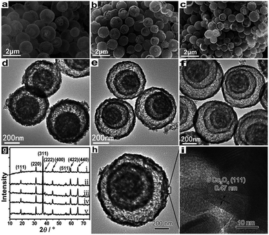 |
| | Fig. 15 (a–c) SEM and (d–f) TEM images of double-, triple-, and quadruple-shelled Co3O4 hollow microspheres. (g) XRD patterns of the as-prepared (i) single-, (ii) double-, (iii) triple- and (iv) quadruple-shelled hollow microspheres, and (v) commercial Co3O4. (h) TEM and (i) HRTEM images of an individual triple-shelled Co3O4 hollow microsphere. Reprinted with permission from ref. 43. Copyright 2013, John Wiley & Sons. | |
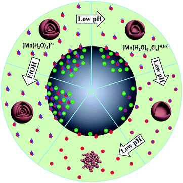 |
| | Fig. 16 Scheme of the synthesis mechanism for Mn2O3 nanoparticles and multi-shelled hollow microspheres under different adsorption conditions. Reprinted with permission from ref. 55. Copyright 2014, John Wiley & Sons. | |
It is worth noting that the penetration of the metal ions is not solely dependent on the electrostatic interactions between the metal cations and negatively charged carbon templates. The abundance of various oxygen-containing functional groups (for example, –OH, –C![[double bond, length as m-dash]](https://www.rsc.org/images/entities/char_e001.gif) O and –C–O–C) in the carbonaceous microsphere templates endows them with the capability to chemically adsorb VO3− despite their negatively charged nature because of the much smaller electrostatic repulsion energy between VO3− and O-containing groups compared with their coordination interactions (chemical bonding effect, as oxygen (O) prefers to donate its p electrons to the empty d orbits of V5+). This concept of competitive anion adsorption by carbon templates overcomes a previous limitation of metal precursors and greatly enriches the variety of available metal oxide hollow microspheres (V2O5, MnO2, MoO3, Cr2O3 and WO3).56
O and –C–O–C) in the carbonaceous microsphere templates endows them with the capability to chemically adsorb VO3− despite their negatively charged nature because of the much smaller electrostatic repulsion energy between VO3− and O-containing groups compared with their coordination interactions (chemical bonding effect, as oxygen (O) prefers to donate its p electrons to the empty d orbits of V5+). This concept of competitive anion adsorption by carbon templates overcomes a previous limitation of metal precursors and greatly enriches the variety of available metal oxide hollow microspheres (V2O5, MnO2, MoO3, Cr2O3 and WO3).56
Besides adsorption manipulation, adjusting the annealing parameters can also allow precise control of the shell size, thickness and inter-shell spacing. For example, we have found that the heating rate has a significant influence on the distribution of Zn ions amongst the outer shells and inner cores and can result in different structures: (1) a fast heating rate results in fewer Zn ions within the outer shells and thus a thin shell is produced; (2) a slow heating rate gives rise to more Zn ions within the outer shells and a closed double-shell is formed at the exterior; (3) a medium heating rate tends to produce a thicker shell. In addition, by carefully optimizing the annealing procedure the inter-shell spacing can be apparently changed (Fig. 18).75 Taking Ti-ion immersed carbon templates as an example, an additional hold period at 470 °C (the temperature at which the first outer shell was formed) and then increasing the temperature to 500 °C to completely remove the templates can result in multi-shelled TiO2 hollow microspheres with adjacent double-shells at the exterior (Fig. 19).76
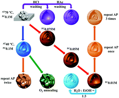 |
| | Fig. 17 Effects of the synthesis conditions on the morphology of V2O5 products. The dark blue arrow indicates a change in the adsorption temperature (AT); the purple arrows indicate treating the carbon-template-V composite microspheres with an acidic solution before calcination; the red arrows indicate a change in the precursor concentration (PC); the orange arrows indicate repeating the adsorption process (AP) before calcination; the light blue arrow indicates increasing the ethanol ratio in the solvent; the green arrow indicates changing the annealing atmosphere from air to oxygen. Reprinted with permission from ref. 56. Copyright 2016, Nature Publishing Group. | |
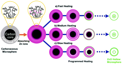 |
| | Fig. 18 Illustration of the formation of multi-shelled ZnO hollow microspheres through different heating processes. Reprinted with permission from ref. 75. Copyright 2012, John Wiley & Sons. | |
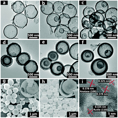 |
| | Fig. 19 TEM micrographs of (a) 1S-TiO2-HMS, (b) 2S-TiO2-HMS, (c) 3S-TiO2-HMS, (d) 2S-TiO2-HMS-CDS, (e) 3S-TiO2-HMS-CDS, and (f) 4S-TiO2-HMS-CDS. SEM micrographs of (g) 3S-TiO2-HMS and (h) 3S-TiO2-HMS-CDS. (i) High resolution TEM micrograph of 3S-TiO2-HMS. Reprinted with permission from ref. 76. Copyright 2014, American Chemical Society. | |
4. Lithium-ion battery characteristics of multi-shelled hollow micro-/nanostructures
Benefiting from their larger surface area, shorter transport path length for charges and ions, and better buffering of volume changes as well as induced stress/strain, multi-shelled hollow micro-/nanostructures have been considered as very promising electrode materials for lithium-ion batteries. As summarized in Table 2, numerous studies about the utilization of multi-shelled hollow micro-/nanostructures as lithium-ion battery electrodes have been reported in the past few decades. Besides, from Table 2, we can clearly see that compared to their corresponding solid/single-shelled hollow sample, the capacity, stability and rate capability of the hollow structures as lithium-ion battery electrode materials are improved simultaneously and substantially. In this part, we summarize the recent progress and introduce some perspectives on the application of multi-shelled hollow micro-/nanostructured materials in LIBs. As discussed in Section 2.1, electrode materials can be classified into three types according to their different charge-storage mechanisms:86,87 (1) insertion/extraction type materials (nearly all the cathode materials, such as V2O5 and LiMn2O4, and anode materials such as carbon, Li4Ti5O12 and TiO2); (2) alloying/de-alloying type materials (such as SnOx or SnS); (3) conversion reaction type materials (such as Co3O4, Fe2O3, Mn2O3, NiO or AB2O4 (A, B = Mn, Co, Fe, Ni, Cu, Zn)). For electrode materials with different charge-storage mechanisms, the Li storage amount and sites can be quite different from each other, inducing different theoretical capacities and cycling stabilities. Specifically, the cycling stability of insertion/extraction type materials is good, yet their theoretical capacity is low; alloying/de-alloying type materials provide a higher theoretical capacity but a poor cycling stability; and as for conversion reaction type materials, both the theoretical capacity and cycling stability are in between those of the other two types of electrode materials. To make the best of their advantages and meanwhile avoid the deficiencies, the compositional and geometric parameters of different types of electrode materials have been manipulated accordingly.
Table 2 The morphologies, synthetic routes and lithium-ion battery characteristics of various multi-shelled hollow structures presented in the literature
| Material |
Morphology |
Method characteristics |
Shell number |
Specific capacity (mA h g−1)/rate (mA g−1) |
Stability stable capacity (mA h g−1)/cycling number |
Rate capability capacity (mA h)/rate (A g−1) |
Performance-improvement percentage (%) |
Ref. |
| Notes: ST means a sequential template method. Performance-improvement percentage represents the ratio of the stable capacity after several cycles for the multi-shelled hollow micro/nano-structures to that of their corresponding solid/single-shelled sample. — means there is no LIB data reported for the solid sample in the literature. GNS* means graphene nanosheets. |
| V2O5 |
Sphere |
ST |
3 |
447.9/1000 |
402.4/100 |
331.8/2 |
500 |
56
|
| LiMn2O4 |
Sphere |
ST |
3 |
145.9/29.6 |
∼135/10 |
113.3/1.48 |
172 |
90
|
| LiMn2O4 |
Sphere |
ST |
3–4 |
143.4/148 |
97.7/100 |
103/1.48 |
— |
91
|
| LiMn2O4 |
Sphere |
ST |
3 |
110/200 |
101.3/400 |
94.7/1 |
145 |
92
|
| Carbon |
Sphere |
Shell-by-shell coating |
1–3 |
304/5000 |
240/500 |
236/10 |
205 |
93
|
| Carbon |
Sphere |
SiO2 templating |
1–4 |
∼2500/50 |
977.6/50 |
317/0.8 |
320 |
69
|
| TiO2 |
Sphere |
ST |
1–3 |
260/168 |
237/100 |
129/1.68 |
280 |
76
|
| SnO2 |
Sphere |
ST |
1–4 |
861/100 |
214/100 |
112/2 |
— |
95
|
| SnS |
Sphere |
ST |
3 |
1487/1000 |
672/150 |
480/5 |
— |
96
|
| NiO |
Sphere |
ST |
1–4 |
1167/200 |
139.4/100 |
356/0.6 |
300 |
97
|
| Co3O4 |
Sphere |
Vesicle templating |
1–3 |
753/198 |
866/50 |
500.8/1.98 |
127 |
98
|
| Co3O4 |
Sphere |
ST |
1–4 |
2063.7/50 |
1615.8/30 |
1117.3/2 |
560 |
43
|
| Co3O4 |
Sphere |
ST |
4–6 |
1331/500 |
958/100 |
770/3 |
— |
99
|
| α-Fe2O3 |
Sphere |
ST |
1–4 |
2345/50 |
1702/50 |
1100/1 |
396 |
79
|
| α-Fe2O3 |
Sphere |
ST |
1–4 |
1443/50 |
1000/50 |
784/3.2 |
— |
100
|
| α-Fe2O3 |
Sphere |
ST |
4 |
∼1800/100 |
1202.8/120 |
498.1/6 |
— |
101
|
| α-Fe2O3 |
Sphere |
ST |
3–4 |
1360/400 |
861/50 |
294/4 |
— |
102
|
| Mn2O3 |
Nanocube |
ST |
3 |
606/500 |
533/100 |
350/2 |
— |
103
|
| Mn2O3 |
Sphere |
ST |
3 |
1416.1/— |
142.2/250 |
— |
190 |
104
|
| NiO/GNS* |
Sphere |
ST |
3 |
1100/200 |
261.5/100 |
166.5/1 |
— |
105
|
| CuO@NiO |
Sphere |
ST |
3 |
1218/100 |
1061/200 |
— |
158 |
106
|
| MgCo2O4 |
Sphere |
ST |
4 |
1130/500 |
1360/100 |
856/10 |
— |
107
|
| CoMn2O4 |
Sphere |
ST |
3 |
1029/1600 |
579/40 |
443/3.2 |
200 |
108
|
| CoMn2O4 |
Sphere |
ST |
1–4 |
1006.6/200 |
726.7/200 |
449.8/3.2 |
— |
48
|
| NiCo2O4 |
Sphere |
ST |
3 |
1401/150 |
706/100 |
533/2 |
— |
109
|
| Ni1−xCo2O4−x |
Sphere |
ST |
3–5 |
1202/1000 |
913/100 |
670/5 |
— |
78
|
| ZnCo2O4 |
Sphere |
ST |
3 |
1101/3000 |
753/200 |
640/10 |
365 |
110
|
| ZnMn2O4 |
Sphere |
ST |
2–3 |
1554.2/200 |
868/60 |
528/2 |
— |
111
|
| ZnO–Mn3O4 |
Sphere |
ST |
2–4 |
1470/700 |
912/100 |
460/3 |
— |
112
|
| MnxCo1−xFe2O4 |
Sphere |
ST |
3 |
846.6/200 |
498.3/500 |
115.3/2 |
— |
113
|
4.1 Insertion/extraction type
All cathode materials are based on an insertion/extraction charge-storage mechanism, as well as some anode materials such as carbon-based materials (graphite, carbon nanotubes (CNTs), graphene, and porous carbon), TiO2, and Li4Ti5O12. The overall insertion/extraction reaction is summarized as follows:| | | MOz + xLi+ + xe− ↔ LixMOz (M = V, Ti and W) | (2) |
Recently our group reported the synthesis of multi-shelled V2O5 hollow microspheres with a well-controlled shell number, thickness, porosity and crystallinity (Fig. 17), through using a novel concept of competitive anion adsorption by CMS templates followed with a Trojan catalytic combustion process.56 Benefiting from the superiority of multi-shelled hollow structures, MS-V2O5-HMSs exhibit superb lithium-storage properties when used as cathode materials for LIBs (Fig. 20). Fig. 20a reveals representative charge/discharge profiles of triple-shelled V2O5 hollow microspheres (3S-V2O5-HMSs) at 1000 mA g−1 between 1.5 V and 4.0 V. It clearly shows a series of phase transformations at approximately 3.25, 3.06, 2.19 and 1.91 V during the initial Li+-intercalation process, which are consistent with previously published results.88,89 Impressively, the 3S-V2O5-HMSs exhibit a record-high initial specific capacity of 447.9 mA h g−1 (theoretically 441 mA h g−1 for V2O5) at 1000 mA g−1. In addition, a good cycling stability (402.4 mA h g−1 after 100 cycles and only 0.10% loss per cycle) and high Coulombic efficiency (CE) (almost 100%) were concurrently achieved, profiting from the superb structural stability and good electrochemical kinetics. Moreover, compared with nanosheets, the 3S-V2O5-HMSs also exhibit an excellent rate capability. Even at a high current density of 2000 mA g−1, the capacity can still remain at 331.8 mA h g−1. The following reasons may be responsible for the high performance of MS-V2O5-HMSs: firstly, the larger specific surface area and pore volume can provide increased lithium-storage sites and greater access for electrolyte penetration, and thus a higher specific capacity; secondly, the diffusion path is greatly reduced with thin porous shells, thus shortening the diffusion time; thirdly, the low ion and mass transfer resistance also contributes to the superior rate capability (Fig. 20d); lastly, the unique structural features (that is, the 3D hollow spherical structures with shells composed of 0D nanoparticles and multiple shells supporting each other) not only allow us to take advantage of low dimensional nanostructures to obtain a high specific capacity, but also to benefit from a better buffering of the volume change and a favourable distribution of the induced stress and strain to achieve excellent cycling stability.
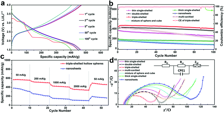 |
| | Fig. 20 Electrochemical properties of as-prepared V2O5 products. (a) Discharge–charge profiles of 3S-V2O5-HMSs for different cycles constantly at 1000 mA g−1. (b) Discharge capacity versus cycle number for the prepared V2O5 hollow microspheres and nanosheets at 1000 mA g−1. (c) Discharge curves of 3S-V2O5-HMSs and V2O5 nanosheets at different current densities. (d) EIS for multi-shelled V2O5 hollow spheres and V2O5 nanosheets (RΩ, external resistance; Rct, charge transfer resistance; CPE1, constant phase element; Zw, Warburg impedance). Reprinted with permission from ref. 56. Copyright 2013, Nature Publishing Group. | |
Besides V2O5, other MS-HMSs cathode materials (such as LiMn2O4) have also been reported,90–92 which all show a much improved LIB performance compared to the commercial ones. For example, we have reported the synthesis of uniform multi-shelled LiMn2O4 hollow microspheres with a high purity.91 Benefiting from the structural features of multi-shelled hollow structures, LiMn2O4 hollow microspheres exhibit a better cycling stability than all the reported results based on uncoated or un-doped LiMn2O4 (the capacity fading rate is only 0.10% per cycle).
Besides cathode materials, some anode materials also share the same insertion/extraction charge-storage mechanism and have also been designed as multi-shelled hollow structures for lithium-ion batteries. For example, our group firstly reported the synthesis of MS-TiO2-HMS with a controlled shell number, shell thickness and inter-shell spacing, which demonstrated significantly improved electrochemical properties.76Fig. 21a shows that the obtained initial discharge capacities of 1S-, 2S- and 3S-TiO2-HMS, and 2S-, 3S-, and 4S-TiO2-HMS-CDS (with closed exterior double-shells) were calculated to be 172, 204, 260, 97, 122, and 154 mA h g−1, respectively. The much higher capacity obtained compared to the theoretical value (∼167 mA h g−1 for rutile/anatase TiO2) was ascribed to the extra capacity contribution from surface lithium storage among the surrounding nano-materials.94 In addition, Fig. 21b highlights that all the multi-shelled structures exhibited a significantly improved cycling performance compared to that of the commercial Degussa P25, especially 3S-TiO2-HMSs which demonstrated the highest specific capacity and best cycling performance. The highest capacity (up to 237 mA h g−1) with minimal irreversible capacity after 100 cycles was achieved with a current rate of 1C (167.5 mA g−1). The reason is that the 3S-TiO2-HMSs have a higher surface area and greater quantity of 10 nm nanopores than those of the 1S- and 2S-TiO2-HMSs, which improves electrolyte transport and Li+ diffusion during the charge/discharge process. Besides, the nano-sized particles of the hierarchical structures, as well as their superior structural stability, allow them to posses a high rate capability and the ability to mitigate strain/stress during the consecutive charge/discharge processes, thus a superior cycling performance is achieved.
 |
| | Fig. 21 (a) Initial charge–discharge voltage profiles and (b) the cycling performance (discharge capacities) with a current rate of 1C between 1.0 and 3.0 V. (c) Cycling performance (discharge capacities) at various charge–discharge current rates for the MS-TiO2-HMS and MS-TiO2-HMS-CDS between 1.0 and 3.0 V. Reprinted with permission from ref. 76. Copyright 2014, American Chemical Society. | |
4.2 Alloying/de-alloying type
The alloying/de-alloying mechanism is another common charge-storage mechanism, which usually occurs in elemental substrates (Si, Ge, Sn, Bi, etc.) and their corresponding oxides or sulfides (such as GeO2, SnS and so on).| | | MOx + 2xLi+ + 2xe− → M + xLi2O | (3) |
| | | MSx + 2xLi+ + 2xe− → M + xLi2S | (4) |
| | | M + xLi+ + xe− → LixM (M = Si, Sn, Sb, and Ge) | (5) |
In the case of pure Zn, Ge, Sn and Si electrodes, charges are stored by forming alloying compounds like LixZn, LixGe, LixSn and LixSi, respectively (eqn (5)). On the other hand, the metal oxide or sulfide based electrodes involve both conversion and alloying/de-alloying mechanisms to form Li2O/Li2S and M, according to eqn (3)/(4) and (5).
Choi et al.96 reported the formation of yolk–shell SnS powders from yolk–shell SnO2. Firstly, the yolk–shell SnO2 structures were prepared directly from a spray solution containing SnSO4 and sucrose, using spray pyrolysis. Notably, spherical, densely structured carbon–SnO2 composite powders were formed as intermediate products in the front part of the reactor through decomposition of SnSO4, polymerization and carbonization processes of the sucrose. Then repeated combustion and contraction processes of the carbon–SnO2 composite occurred in a step-by-step manner to produce a double-shelled SnO2 yolk–shell powder.
Finally, subsequent sulfidation of the yolk–shell SnO2 powders using hydrogen sulfide gas led to the SnS powders. As an anode material for LIBs, the yolk–shell SnS delivers a discharge capacity of 672 mA h g−1 after 150 cycles at a constant rate of 1 A g−1, and the corresponding capacity retention measured after the first cycle was 89%. Besides, the Coulombic efficiency of the yolk–shell SnS powder reached approximately 99% after the third cycle and was maintained in subsequent cycles. Moreover, a capacity of 480 mA h g−1 can still be maintained at a high current density of 5 A g−1 (Fig. 22), indicating an excellent rate capability. The good cycling and rate performance of the yolk–shell SnS powders may be ascribed to their unique structure: the porous yolk–shell structure of the SnS powders provides a reduced Li+ ion diffusion distance and rapid Li+ ion diffusion. The large void volume between the shell and the core facilitates easy and complete penetration of the electrolyte into the microspheres and improves the structural stability of the powder during repeated lithiation and delithiation processes.
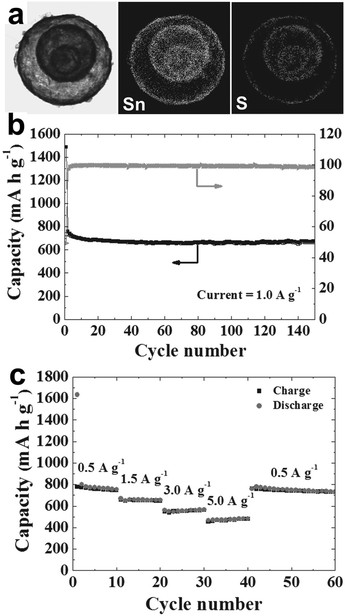 |
| | Fig. 22 (a) Dot-mapping images of the SnS yolk–shell powders; (b) cycle performance and Coulombic efficiencies at a constant current density of 1 A g−1; (c) rate performance. Reprinted with permission from ref. 96. Copyright 2014, John Wiley & Sons. | |
4.3 Conversion reaction type
The conversion reaction mechanism is applicable for most transition-metal oxides, such as Co3O4, Fe2O3, Mn2O3, NiO and AB2O4 (A, B = Mn, Co, Fe, Ni, Cu, Zn). The conversion reactions occur according to the following equation:| | | MzOx + 2xLi+ + 2xe− → zM + xLi2O (M = Mn Fe, Co, and Ni) | (6) |
Since the resulting elementary M (Co, Fe, Mn and Ni) is electrochemically inactive, the main capacity contribution arises from the decomposition and reformation of a Li2O amorphous matrix during the charge/discharge process.
As a representative anode material for LIBs, Co3O4 can deliver a high theoretical capacity of ∼890 mA h g−1. Through forming multi-shelled hollow nanostructures, a much better LIB performance can be achieved compared with commercial materials.43,98,99 Our group has demonstrated that the LIB performance of Co3O4 multi-shelled hollow microspheres could be optimized through accurately controlling the number of shells (1–4) and their interior structures using a hard-template method.43Fig. 23a shows that after 30 cycles, the specific capacities of the single-, double-, triple-, and quadruple-shelled Co3O4 microspheres remained as high as 792.7, 1303, 1615.8 and 1011.5 mA h g−1, respectively, while that of commercial Co3O4 was only 287.5 mA h g−1. Even at a high current density of 2000 mA h g−1, the triple-shelled Co3O4 microspheres could still deliver a capacity of at least 1117.3 mA h g−1. Remarkably, a stable high capacity of 1505 mA h g−1 could still be attained when the current density was reduced back to 50 mA g−1 (see Fig. 23b). This result might suggest that the elastic multi-shelled structures are indeed very “breathable”. In addition, the LIB performance of the triple-shelled Co3O4 microspheres was apparently superior to that of the commercial Co3O4 powder and the three other types of multi-shelled Co3O4 hollow microspheres. This discrepancy may be explained by the different volume-occupying rates of the different microsphere types after Li uptake. As discussed in Section 2.2.2, an appropriate volume-occupying rate, such as that of the triple-shelled Co3O4 microspheres, can guarantee a high volumetric specific capacity as well as a good structure stability, thus leading to the highest lithium storage and best cycling performance.
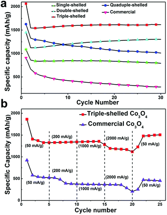 |
| | Fig. 23 (a) Discharge capacity versus cycle number for the prepared Co3O4 hollow microspheres and commercial Co3O4 at a current density of 50 mA g−1; (b) discharge curves for the triple-shelled Co3O4 hollow microspheres and commercial Co3O4 at different current densities. Reprinted with permission from ref. 43. Copyright 2013, John Wiley & Sons. | |
Besides Co3O4, α-Fe2O3 has been studied by several groups79,100–102 as an anode material for LIBs due to its lower toxicity and higher theoretical capacity (1018 mA h g−1). Our group reported the synthesis of multi-shelled α-Fe2O3 hollow microspheres using carbonaceous microsphere sacrificial templates and utilized them for high capacity anode materials in LIBs.79 Their structural aspects, including the shell thickness, number of internal multi-shells, and shell porosity, were controlled using various synthesis parameters to produce hollow microspheres with a maximum lithium capacity and stable cycling behaviour. Fig. 24a shows the charge–discharge profiles of thin triple-shelled hollow microspheres during de/lithiation, which are consistent with the reversible redox conversion of α-Fe2O3 to Fe(0) and Li2O. Fig. 24b demonstrates that the thin-shell hollow microspheres outperformed the thick-shell microspheres, with stable capacities of 1508, 1607, and 1702 mA h g−1 for the single, double, and triple-shelled α-Fe2O3 hollow microspheres, respectively. The reason is that the lithium storage capacity for the thick-shell hollow microspheres is limited by their slow de/lithiation reaction kinetics and also that the capacity retention fades considerably with cycle number. As expected, the triple-shelled hollow spheres also show a good rate capability: a stable capacity of 1100 mA h g−1 still can be obtained at a high current density of 1000 mA g−1.
 |
| | Fig. 24 Comparative cycling performance showing (a) discharge–charge voltage profiles of thin triple-shelled hollow microspheres at different cycle numbers with a constant current density of 50 mA g−1, (b) discharge capacities of thin and thick α-Fe2O3 multi-shelled hollow spheres at a current density of 50 mA g−1, and (c) the rate performance of the thin-shell hollow spheres according to the cycling rate sequence: 50, 100, 200, 500, 1000 and 50 mA g−1. All galvanostatic tests were performed between 0.05 and 3 V. Capacities reported are based on the mass of α-Fe2O3 in the anodes. Reprinted with permission from ref. 84. Copyright 2014, Royal Society of Chemistry Publishing. | |
Improved lithium storage properties have also been reported for many other electrode materials through adopting hollow micro-/nanostructures, including Mn2O3,103,104 NiO,105 CuO@NiO,106 and even complex binary AxB2−xO448,78,107–112 and ternary AxByC2−x−yO4 (A, B, C = Zn, CO, Mn, Ni, Cu, Fe)113 metal oxides. All these results clearly prove the great advantages of using multi-shelled hollow micro-/nanostructured materials as electrodes for LIBs. However, to achieve industrial-grade success with these multi-shelled hollow micro-/nanostructures as LIB electrodes, continued fundamental advances in the science and engineering of the materials' composition, morphology and structure are still urgently needed.
5. Summary and outlook
In summary, due to their fascinating structural characteristics, such as a larger surface area, tunable shell number, thickness, spacing and grain size, multi-shelled hollow micro/nanostructures demonstrate promising potential for use in lithium-ion batteries with abundant Li storage sites, a shorter transport path length and improved buffering of the volume change induced by stress/strain in consecutive cycling. In this review article, we firstly discussed the principle charge storage mechanisms of lithium ion batteries and correlated the basic compositional and geometric parameters of multi-shelled hollow micro-/nanostructures with the Li storage performance characteristics. After carefully uncovering the structure–performance relationship for multi-shelled hollow micro-/nanostructures, we have presented methodologies for fine control of the compositional and geometric characteristics of multi-shelled hollow micro-/nanostructures. Lastly, the recent progress made in the application of multi-shelled hollow micro-/nanostructures in LIBs was reviewed according to the three different Li storage mechanisms (insertion/extraction, alloying/de-alloying and conversion reaction) to illuminate the advantages of multi-shelled hollow micro-/nanostructures for improving the capacity, stability and rate capability of lithium ion batteries simultaneously and substantially.
While multi-shelled hollow micro-/nanostructures have provided great success within lithium ion batteries, challenges still exist within both the material synthesis and electrochemical performance, and future research is still necessary for various aspects. Firstly, there is still a lack of a series of general high-throughput methods for synthesizing high quality multi-shelled hollow micro-/nanostructures with accurately controlled geometric and compositional parameters. As discussed above, compared to other methods, the sequential templating method is more general and more likely to develop into a universal method for synthesizing various multi-shelled hollow micro-/nanostructures with the shell parameters accurately controlled through adjustment of the synthesis parameters, such as the precursor solution, solvent type, pH value, solution temperature, adsorption duration, heating rate, temperature and atmosphere. As we can expect, with the help of theoretical modelling and calculations, the synthesis parameters for these special-composition structures could be quantified, thus achieving accurate control over the geometric parameters of the multi-shelled hollow micro-/nanostructures.
Secondly, the structure–performance relationship of multi-shelled hollow structures for LIBs is still ambiguous, for example, concerning the atomic-level reaction process that occurs during the Li insertion/extraction. Some in situ and ex situ characterization is still needed to fully understand the structural advantages of multi-shelled hollow structures for use in LIBs. Also, basic theoretical calculations and modeling may help to unravel the detailed atomic processes. Finally, the development of large-scale, low-cost fabrication strategies for the fabrication of electrodes with a desirable performance is an important challenge. For example, carbon coating and/or hybridization with other efficient conductive materials have already been demonstrated as effective ways to further improve the high rate performance, as reported in the literature. However, the volume capacity and tap density of the multi-shelled hollow structures are still bottlenecks toward their large-scale commercial application and should be explored extensively.
Acknowledgements
This work was supported financially by the National Natural Science Foundation of China (No. 51172235, 21203201, 51202248, 21201167, 51272165, 51372245, 51302266, 51472244, 51572261, 21401199, 51362024 and 21590795), CAS Interdisciplinary Innovation Team, Australian Research Council (ARC) Discovery Project (No. 160104817), and National Science Fund for Distinguished Young Scholars (No. 21325105).
Notes and references
- Y. Wang and G. Z. Cao, Adv. Mater., 2008, 20, 2251 CrossRef CAS.
- B. Wang, Y. Wang, B. Sun, P. Munroe and G. X. Wang, RSC Adv., 2013, 3, 5069 RSC.
- K. X. Wang, X. H. Li and J. S. Chen, Adv. Mater., 2014, 27, 527 CrossRef PubMed.
- G. G. Eshetu, M. Armand, B. Scrosati and S. Passerini, Angew. Chem., Int. Ed., 2014, 53, 13342 CrossRef PubMed.
- S. Evers and L. F. Nazar, Acc. Chem. Res., 2013, 46, 1135 CrossRef CAS PubMed.
- P. Poizot, S. Laruelle, S. Grugeon, L. Dupont and J.-M. Tarascon, Nature, 2000, 407, 496 CrossRef CAS PubMed.
- J. B. Goodenough and Y. Kim, Chem. Mater., 2010, 22, 587 CrossRef CAS.
- Y. Idota, T. Kubota, A. Matsufuji, Y. Maekawa and T. Miyasaka, Science, 1997, 276, 1395 CrossRef CAS.
- X. W. Lou, L. A. Archer and Z. C. Yang, Adv. Mater., 2008, 20, 3987 CrossRef CAS.
- X. L. Wu, Y. G. Guo and L. J. Wan, Chem. – Asian J., 2013, 8, 1948 CrossRef CAS PubMed.
- M. P. Palacín, Chem. Soc. Rev., 2009, 28, 2565 RSC.
- M. V. Reddy, G. V. S. Rao and B. V. R. Chowdari, Chem. Rev., 2013, 113, 5364 CrossRef CAS PubMed.
- H. Wu and Y. Cui, Nano Today, 2012, 7, 414 CrossRef CAS.
- J. Liu and D. F. Xue, Nanoscale Res. Lett., 2010, 5, 525 Search PubMed.
- C. K. Chan, H. L. Peng, G. Liu, K. McIlwrath, X. F. Zhang, R. A. Huggins and Y. Cui, Nat. Nanotechnol., 2008, 3, 31 CrossRef CAS PubMed.
- X. L. Ji, K. T. Lee and L. F. Nazar, Nat. Mater., 2009, 8, 500 CrossRef CAS PubMed.
- H. Kim, B. Han, J. Choo and J. Cho, Angew. Chem., Int. Ed., 2008, 47, 10151 CrossRef CAS PubMed.
- G. Derrien, J. Hassoun, S. Panero and B. Scrosati, Adv. Mater., 2007, 19, 2336 CrossRef CAS.
- S. Li, J. J. Niu, Y. C. Zhao, K. P. So, C. Wang, C. A. Wang and J. Li, Nat. Commun., 2015, 6, 7872 CrossRef CAS PubMed.
- J. F. Ye, H. J. Zhang, R. Yang, X. G. Li and L. M. Qi, Small, 2010, 6, 296 CrossRef CAS PubMed.
- J. Chen, L. Xu, W. Y. Li and X. L. Gou, Adv. Mater., 2005, 17, 582 CrossRef CAS.
- F. Zhan, B. Geng and Y. Guo, Chem. – Eur. J., 2009, 15, 6169 CrossRef CAS PubMed.
- B. Varghese, M. V. Reddy, Z. Yanwu, C. S. Lit, T. C. Hoong, G. V. S. Rao, V. R. Chowdari, A. T. S. Wee, C. T. Lim and C.-H. Sow, Chem. Mater., 2008, 20, 3360 CrossRef CAS.
- Z. Y. Wang, L. Zhou and X. W. Lou, Adv. Mater., 2012, 24, 1903 CrossRef CAS PubMed.
- N. Liu, Z. D. Lu, J. Zhao, M. T. Mcdowell, H.-W. Lee, W. T. Zhao and Y. Cui, Nat. Nanotechnol., 2014, 9, 187 CrossRef CAS PubMed.
- G. Q. Zhang, L. Yu, H. B. Wu, H. E. Hoster and X. W. Lou, Adv. Mater., 2012, 4, 4609 CrossRef PubMed.
- A. Q. Pan, H. B. Wu, L. Yu and X. W. Lou, Angew. Chem., Int. Ed., 2013, 52, 2226 CrossRef CAS PubMed.
- L. F. Shen, L. Yu, H. B. Wu, X.-Y. Yu, X. G. Zhang and X. W. Lou, Nat. Commun., 2015, 6, 6694 CrossRef CAS PubMed.
- X.-Y. Yu, L. Yu and X. W. Lou, Adv. Energy Mater., 2016, 6, 1501333 CrossRef.
- Y. W. Wang, L. Yu and X. W. Lou, Angew. Chem., Int. Ed., 2016, 55, 14668 CrossRef CAS PubMed.
- Y. Zhao and L. Jiang, Adv. Mater., 2009, 21, 3621 CrossRef CAS.
- X. Y. Lai, J. E. Halpert and D. Wang, Energy Environ. Sci., 2012, 5, 5604 CAS.
- J. Qi, X. Y. Lai, J. Y. Wang, H. J. Tang, H. Ren, Y. Yang, Q. Jin, L. J. Zhang, R. B. Yu, G. H. Ma, Z. G. Su, H. J. Zhao and D. Wang, Chem. Soc. Rev., 2015, 44, 6749 RSC.
- C. W. Sun, S. Rajasekhara, J. B. Goodenough and F. Zhou, J. Am. Chem. Soc., 2011, 133, 2132 CrossRef CAS PubMed.
- X. B. Yu, B. Qu, Y. Zhao, C. Y. Li, Y. J. Chen, C. W. Sun, P. Gao and C. L. Zhu, Chem. – Eur. J., 2016, 22, 1638 CrossRef CAS PubMed.
- M. Sasidharan and K. Nakashima, Acc. Chem. Res., 2014, 47, 157 CrossRef CAS PubMed.
- G. L. Li, H. Möhwald and D. G. Shchukin, Chem. Soc. Rev., 2013, 42, 3628 RSC.
- Y. S. Li and J. L. Shi, Adv. Mater., 2014, 26, 3176 CrossRef CAS PubMed.
- M. S. Whittingham, Chem. Rev., 2004, 104, 4271 CrossRef CAS PubMed.
- M. Hu, X. L. Pang and Z. Zhen, J. Power Sources, 2013, 237, 229 CrossRef CAS.
- Z. Chen, C. Wang, J. L. Lopez, Z. D. Lu, Y. Cui and Z. N. Bao, Adv. Energy Mater., 2015, 1401826 CrossRef.
- D. C. Lin, Z. D. Lu, P.-C. Hsu, H. R. Lee, N. Liu, J. Zhao, H. T. Wang, C. Liu and Y. Cui, Energy Environ. Sci., 2015, 8, 2371 CAS.
- J. Y. Wang, N. L. Yang, H. J. Tang, Z. H. Dong, Q. Jin, M. Yang, D. Kisailus, H. J. Zhao, Z. Y. Tang and D. Wang, Angew. Chem., Int. Ed., 2013, 52, 6417 CrossRef CAS PubMed.
- H. S. Zhou, D. L. Li, M. Hibino and I. Honma, Angew. Chem., Int. Ed., 2005, 44, 797 CrossRef CAS PubMed.
- X. Li, L. Wang, J. Shi, N. Du and G. He, ACS Appl. Mater. Interfaces, 2016, 8, 17276 CAS.
- X. Y. Lai, J. Li, B. A. Korgel, Z. H. Dong, Z. M. Li, F. B. Su, J. Du and D. Wang, Angew. Chem., Int. Ed., 2011, 50, 2738 CrossRef CAS PubMed.
- Z. M. Li, X. Y. Lai, H. Wang, D. Mao, C. J. Xing and D. Wang, J. Phys. Chem. C, 2009, 113, 2792 CAS.
- G. Q. Zhang and X. W. Lou, Angew. Chem., Int. Ed., 2014, 53, 9041 CrossRef CAS PubMed.
- W. Cho, Y. H. Lee, H. J. Lee and M. Oh, Adv. Mater., 2011, 23, 1720 CrossRef CAS PubMed.
- Y. J. Hong, M. Y. Son, B. K. Park and Y. C. Kang, Small, 2013, 13, 2224 CrossRef PubMed.
- S. L. Xiong and H. C. Zeng, Angew. Chem., Int. Ed., 2012, 51, 949 CrossRef CAS PubMed.
- S. H. Choi and Y. C. Kang, ACS Appl. Mater. Interfaces, 2015, 7, 24694 CAS.
- J. A. Acapuco Jr., S. Hong, S. K. Kim and S. Park, J. Colloid Interface Sci., 2016, 461, 376 CrossRef PubMed.
- Z. Y. Wang, Z. C. Wang, H. B. Wu and X. W. Lou, Sci. Rep., 2013, 3, 1391 Search PubMed.
- J. Y. Wang, H. J. Tang, H. Ren, R. B. Yu, J. Qi, D. Mao, H. J. Zhao and D. Wang, Adv. Sci., 2014, 1, 1400011 CrossRef PubMed.
- J. Y. Wang, H. J. Tang, L. J. Zhang, H. Ren, R. B. Yu, Q. Jin, J. Qi, D. Mao, M. Yang, Y. Wang, P. R. Liu, Y. Zhang, Y. R. Wen, L. Gu, G. H. Ma, Z. G. Su, Z. Y. Tang, H. J. Zhao and D. Wang, Nat. Energy, 2016, 1, 16072 CrossRef.
- M. J. Chen, J. Y. Wang, H. J. Tang, Y. Yang, B. Wang, H. J. Zhao and D. Wang, Inorg. Chem. Front., 2016, 3, 1065 RSC.
- Z. Z. Li, Y. Zhang, Z. Z. Chen and E. W. Shi, J. Inorg. Mater., 2009, 24, 1263 CAS.
- J. Liu, S. B. Hartono, Y. G. Jin, Z. Li, G. Q. Lu and S. Z. Qiao, J. Mater. Chem., 2010, 20, 4595 RSC.
- F. Zhang, K. X. Wang, X. Y. Wang, G. D. Li and J. S. Chen, Dalton Trans., 2011, 40, 8517 RSC.
- C. C. Yec and H. C. Zeng, Chem. Mater., 2012, 24, 1917 CrossRef CAS.
- Z. H. Dong, H. Ren, C. M. Hessel, J. Y. Wang, R. B. Yu, Q. Jin, M. Yang, Z. D. Hu, Y. F. Chen, Z. Y. Tang, H. J. Zhao and D. Wang, Adv. Mater., 2014, 26, 905 CrossRef CAS PubMed.
- X. M. Ma, X. T. Zhang, L. Yang, K. Wang, K. Jiang, Z. P. Wei and Y. M. Guo, CrystEngComm, 2014, 16, 7933 RSC.
- Z. H. Yang, F. F. Xu, W. X. Zhang, Z. S. Mei, B. Pei and X. Zhu, J. Power Sources, 2014, 246, 24 CrossRef CAS.
- J. Q. Zhao and Y. Wang, ECS Trans., 2014, 61, 83 CrossRef.
- J. Qi, K. Zhao, G. D. Li, Y. Gao, H. J. Zhao, R. B. Yu and Z. Y. Tang, Nanoscale, 2014, 6, 4072 RSC.
- Z. G. Teng, X. D. Su, Y. Y. Zheng, J. J. Zhang, Y. Liu, S. J. Wang, J. Wu, G. T. Chen, J. D. Wang, D. Y. Zhao and G. M. Lu, J. Am. Chem. Soc., 2015, 137, 7935 CrossRef CAS PubMed.
- H. M. Sun, L. M. Wang, D. Q. Chu, Z. C. Ma and A. X. Wang, Mater. Lett., 2015, 140, 158 CrossRef CAS.
- Z. Sun, X. F. Song, P. Zhang and L. Gao, RSC Adv., 2015, 5, 3657 RSC.
- L. B. Zong, P. F. Xu, Y. J. Ding, K. Zhao, Z. M. Wang, X. C. Yan, R. B. Yu, J. Chen and X. R. Xing, Small, 2015, 11, 2768 CrossRef CAS PubMed.
- L. Wu, H. J. Zhang, M. H. Wu, Y. F. Zhong, X. W. Liu and Z. Jiao, Microporous Mesoporous Mater., 2016, 228, 318 CrossRef CAS.
- X. M. Ma, X. T. Zhang, L. Yang, G. Wang, K. Jiang, G. Wu, W. G. Cui and Z. P. Wei, Nanoscale, 2016, 8, 8687 RSC.
- M. P. Nikhila and N. K. Renuka, RSC Adv., 2016, 6, 24210 RSC.
- J.-S. Kim, J.-W. Yoon, Y. J. Hong, Y. C. Kang, F. Abdel-Hady, A. A. Wazzan and J.-H. Lee, Sens. Actuators, B, 2016, 229, 561 CrossRef CAS.
- Z. H. Dong, X. Y. Lai, J. E. Halpert, N. L. Yang, L. X. Yi, J. Zhai, D. Wang, Z. Y. Tang and L. Jiang, Adv. Mater., 2012, 24, 1046 CrossRef CAS PubMed.
- H. Ren, R. B. Yu, J. Y. Wang, Q. Jin, M. Yang, D. Mao, D. Kisailus, H. J. Zhao and D. Wang, Nano Lett., 2014, 14, 6679 CrossRef CAS PubMed.
- X. W. Lou, C. L. Yuan and L. A. Archer, Small, 2007, 3, 261 CrossRef CAS PubMed.
- S. H. Choi, S. K. Park, J.-K. Lee and Y. C. Kang, J. Power Sources, 2015, 284, 481 CrossRef CAS.
- S. M. Xu, C. M. Hessel, H. Ren, R. B. Yu, Q. Jin, M. Yang, H. J. Zhao and D. Wang, Energy Environ. Sci., 2014, 7, 632 CAS.
- W. Xia, C. Mei, X. Zeng, S. Chang, G. Wu and X. Shen, Appl. Phys. Lett., 2016, 108, 113902 CrossRef.
- T. Gan, A.-X. Zhao, S.-H. Wang, Z. Lv and J.-Y. Sun, Sens. Actuators, B, 2016, 235, 707 CrossRef CAS.
- S. Niu, Y. Wang, S. Lu, D. Wang and P. Wang, Solid State Sci., 2016, 56, 63 CrossRef CAS.
- Z. Wang, W. Jia, M. Jiang, C. Chen and Y. Li, Nano Res., 2016, 9, 2026 CrossRef CAS.
- S. K. S. Patel, S. H. Choi, Y. C. Kang and J.-K. Lee, Nanoscale, 2016, 8, 6728 RSC.
- T. Wang, W. Cui, M. Peng, S. Ouyang and S. Wang, J. Mater. Chem. A, 2016, 4, 8584 CAS.
- S. Yuvaraj, R. K. Selvan and Y. S. Lee, RSC Adv., 2016, 6, 21448 RSC.
- D. Deng, Energy Sci. Eng., 2015, 3, 385 CrossRef.
- A. Q. Pan, H. B. Wu, L. Zhang and X. W. Lou, Energy Environ. Sci., 2013, 6, 1476 CAS.
- G. D. Du, K. H. Seng, Z. P. Guo, J. Liu, W. X. Li, D. Z. Jia, C. Cook, Z. W. Liu and H. Liu, RSC Adv., 2011, 1, 690 RSC.
- B. Li, X. G. Wei, Z. R. Chang, X. N. Chen, X.-Z. Yuan and H. J. Wang, Mater. Lett., 2014, 135, 75 CrossRef CAS.
- F. Wang, J. Y. Wang, H. Ren, H. J. Tang, R. B. Yu and D. Wang, Inorg. Chem. Front., 2016, 3, 365 RSC.
- X. F. Niu, Y. F. Li, Y. J. Hu, H. Jiang, X. Y. Hou, W. G. Li, S. J. Qiu and C. Z. Li, New J. Chem., 2016, 40, 1839 RSC.
- J. Zang, J. C. Ye, X. L. Fang, X. W. Zhang, M. S. Zheng and Q. F. Dong, Electrochim. Acta, 2015, 186, 436 CrossRef CAS.
- Y. F. Zhukovskii, P. Balaya, E. A. Kotomin and J. Maier, Phys. Rev. Lett., 2006, 96, 058302 CrossRef PubMed.
- G. Wu, H. Wu, K. Wang, C. Zheng, Y. Wang and A. Feng, RSC Adv., 2016, 6, 58069 RSC.
- S. H. Choi and Y. C. Kang, Small, 2014, 10, 474 CrossRef CAS PubMed.
- H. Wu, Y. Wang, C. Zheng, J. Zhu, G. Wu and X. Li, J. Alloys Compd., 2016, 685, 8 CrossRef CAS.
- X. Wang, X. L. Wu, Y. G. Guo, Y. T. Zhong, X. Q. Cao, Y. Ma and J. N. Yao, Adv. Funct. Mater., 2010, 20, 1680 CrossRef CAS.
- G. D. Park, J.-H. Lee, J.-K. Lee and Y. C. Kang, Nano Res., 2014, 7, 1738 CrossRef CAS.
- L. Zhou, H. Y. Xu, H. W. Zhang, J. Yang, S. B. Hartono, K. Qian, J. Zou and C. Z. Yu, Chem. Commun., 2013, 49, 8695 RSC.
- Z. G. Wu, Y. J. Zhong, J. T. Li, X. D. Guo, L. Huang, B. H. Zhong and S. G. Sun, J. Mater. Chem. A, 2014, 2, 12361 CAS.
- Z. Padashbarmchi, A. H. Hamidian, H. W. Zhang, L. Zhou, N. Khorasani, M. Kazemzad and C. Z. Yu, RSC Adv., 2015, 5, 10304 RSC.
- H. B. Lin, H. B. Rong, W. Z. Huang, Y. H. Liao, L. D. Xing, M. Q. Xu, X. P. Li and W. S. Li, J. Mater. Chem. A, 2014, 2, 14189 CAS.
- Y. Wang, S. S. Niu and S. Lu, Mater. Lett., 2015, 158, 416 CrossRef CAS.
- L. H. Chu, M. C. Li, Y. Wang, X. D. Li, Z. P. Wan, S. Y. Dou and Y. Chu, J. Nanomater., 2016, 4901847 Search PubMed.
- W. X. Guo, W. W. Sun and Y. Wang, ACS Nano, 2015, 9, 11462 CrossRef CAS PubMed.
- H. Shin and W.-J. Lee, J. Mater. Chem. A, 2016, 4, 12263 CAS.
- M. H. Kim, Y. J. Hong and Y. C. Kang, RSC Adv., 2013, 3, 13110 RSC.
- L. F. Shen, L. Yu, X.-Y. Xu, X. G. Zhang and X. W. Lou, Angew. Chem., Int. Ed., 2015, 54, 1868 CrossRef CAS PubMed.
- S. H. Choi and Y. C. Kang, ChemSusChem, 2013, 6, 2111 CrossRef CAS PubMed.
- X. Zhang, Y. L. Wang, H. F. Jiu, H. Y. Qiu and H. Y. Wang, Ceram. Int., 2015, 41, 9655 CrossRef.
- S. H. Choi and Y. C. Kang, Chem. – Eur. J., 2014, 20, 3014 CrossRef CAS PubMed.
- Z. L. Zhang, Y. J. Ji, J. Li, Q. Q. Tan, Z. Y. Zhong and F. B. Su, ACS Appl. Mater. Interfaces, 2015, 7, 6300 CAS.
Footnote |
| † These authors contributed equally. |
|
| This journal is © the Partner Organisations 2017 |
Click here to see how this site uses Cookies. View our privacy policy here. 


![[double bond, length as m-dash]](https://www.rsc.org/images/entities/char_e001.gif) O and –C–O–C) in the carbonaceous microsphere templates endows them with the capability to chemically adsorb VO3− despite their negatively charged nature because of the much smaller electrostatic repulsion energy between VO3− and O-containing groups compared with their coordination interactions (chemical bonding effect, as oxygen (O) prefers to donate its p electrons to the empty d orbits of V5+). This concept of competitive anion adsorption by carbon templates overcomes a previous limitation of metal precursors and greatly enriches the variety of available metal oxide hollow microspheres (V2O5, MnO2, MoO3, Cr2O3 and WO3).56
O and –C–O–C) in the carbonaceous microsphere templates endows them with the capability to chemically adsorb VO3− despite their negatively charged nature because of the much smaller electrostatic repulsion energy between VO3− and O-containing groups compared with their coordination interactions (chemical bonding effect, as oxygen (O) prefers to donate its p electrons to the empty d orbits of V5+). This concept of competitive anion adsorption by carbon templates overcomes a previous limitation of metal precursors and greatly enriches the variety of available metal oxide hollow microspheres (V2O5, MnO2, MoO3, Cr2O3 and WO3).56


