 Open Access Article
Creative Commons Attribution 3.0 Unported Licence
Location of CO2 during its uptake by the flexible porous metal–organic framework MIL-53(Fe): a high resolution powder X-ray diffraction study†
Nathalie
Guillou
a,
Sandrine
Bourrelly
b,
Philip L.
Llewellyn
b,
Richard I.
Walton
*c and
Franck
Millange
*a
aInstitut Lavoisier Versailles, Université de Versailles, UMR 8180, 78035 Versailles, France. E-mail: franck.millange@uvsq.fr
bAix-Marseille University, Laboratoire MADIREL, UMR CNRS 7246, Centre de St Jérôme, 13397 Marseille Cedex 20, France
cDepartment of Chemistry, University of Warwick, Coventry, CV4 7AL, UK. E-mail: r.i.walton@warwick.ac.uk
First published on 5th September 2014
Abstract
The interaction of CO2 with the porous metal–organic framework material MIL-53(Fe), FeIII(OH)0.8F0.2[O2C–C6H4–CO2] has been studied by complementary gas adsorption and high resolution powder X-ray diffraction as a function of gas pressure. It has been shown that CO2 adsorption occurs in three steps, with firstly the formation of an “Intermediate” (INT) form [S. G. P![[1 with combining macron]](https://www.rsc.org/images/entities/char_0031_0304.gif) ; V = 916.80(6) Å3] at room temperature and 2 bar, followed by the transition to a “Narrow Pore” (NP) form [S. G. C2/c; V = 1083.01(2) Å3] at 10 bar. The “Large Pore” (LP) form [S. G. Imcm; V = 1563.10(4) Å3] is obtained also at 10 bar but by decreasing the temperature to 220 K. Crystal structures of the three CO2 materials MIL-53(Fe)[nCO2], with n = 0.22, 0.63 and 2.72, have been solved and refined, which has allowed precise localisation of guest CO2 molecules, not previously determined. This shows that the (INT) form presents two types of tunnels of different sizes, with only the largest ones are occupied by the CO2 molecules. In the (NP) and (LP) forms, all tunnels become equivalent and are occupied by CO2. The huge unit cell volume increase of the (LP) form leads to drastic increase in the amount of CO2 adsorbed. In the three forms, CO2 molecules are located in order to favour interactions between their oxygen atoms and the OH/F groups of the framework and there is no evidence for guest–guest interactions until the highest loading where short contacts of a similar distance found in solid CO2 are observed.
; V = 916.80(6) Å3] at room temperature and 2 bar, followed by the transition to a “Narrow Pore” (NP) form [S. G. C2/c; V = 1083.01(2) Å3] at 10 bar. The “Large Pore” (LP) form [S. G. Imcm; V = 1563.10(4) Å3] is obtained also at 10 bar but by decreasing the temperature to 220 K. Crystal structures of the three CO2 materials MIL-53(Fe)[nCO2], with n = 0.22, 0.63 and 2.72, have been solved and refined, which has allowed precise localisation of guest CO2 molecules, not previously determined. This shows that the (INT) form presents two types of tunnels of different sizes, with only the largest ones are occupied by the CO2 molecules. In the (NP) and (LP) forms, all tunnels become equivalent and are occupied by CO2. The huge unit cell volume increase of the (LP) form leads to drastic increase in the amount of CO2 adsorbed. In the three forms, CO2 molecules are located in order to favour interactions between their oxygen atoms and the OH/F groups of the framework and there is no evidence for guest–guest interactions until the highest loading where short contacts of a similar distance found in solid CO2 are observed.
1. Introduction
Porous metal organic frameworks (MOFs) are presently attracting much attention for applications as adsorbents for a variety of guest molecules, in particular for molecular separation and storage of gases such as CO2, CH4 and H2 for environmental and energy reasons, but also of much larger molecules, typically encountered in the liquid phase, ranging from simple hydrocarbons to complex drug molecules.1 In terms of CO2 adsorption the goal of this research is often the capture and storage of large volumes of the gas at close to ambient conditions. In real situations CO2 must often be captured in competition with other potential adsorbate molecules, such as water, sulfur and nitrogen oxides or hydrocarbons, for example, where combustion exhaust gases are being processed. Recent progress in CO2 capture by MOFs has been the subject of several extensive review articles,2 to which the reader is referred. It is clear from this work that diverse methods are being explored to optimise CO2 binding in MOFs, such as inclusion of open metal sites,3 engineering of ligand defects,4 post synthesis partial exchange of metal ions,5 in addition to the use of constricted pores (molecular sieving) familiar from zeolite science.6One interesting strategy in the field of adsorption by porous MOFs is to make use of so-called breathing frameworks whose structure is able to respond to an external stimulus whilst overall connectivity of the structure is maintained.7,8 Such materials have adaptable porosity depending on gas pressure and temperature, for example, which may allow the development of smart porous materials whose structure can respond to conditions of use. Materials with the MIL-53 structure are among the most well-studied examples of breathing MOFs: the structure undergoes a large and reversible structural swelling depending on the presence or absence of guest molecules, an effect which may also be brought about by temperature or pressure.8,9 MIL-53 materials have an anisotropic, three-dimensional structure, being constructed from infinite inorganic chains (trans-corner shared M3+-centred octahedra), cross-linked in two dimensions by the bidentate 1,4-benzenedicarboxylate ligand to give diamond-shaped channels. The trivalent metal in the prototype material may be any one of Cr, Al, Fe, V, Ga, In, Sc, and mixed-metal variants are also known.10 Although some previous studies of CO2 uptake in MIL-53 materials have been reported,11–13 the precise location of the adsorbate as a function of loading has not been determined in most cases. This is largely due to the fact that the materials are only available as polycrystalline samples and structure solution from powder diffraction with large-volume unit cells is not necessarily straightforward; furthermore crystallographic characterisation requires long-range order of guest molecules, which may not always occur in the dynamic conditions of gas adsorption. In this paper we present a study of CO2 uptake by MIL-53(Fe) in which we use knowledge gained from gas adsorption studies to interpret high-resolution powder X-ray diffraction patterns from samples loaded in situ with CO2. The use of high-resolution synchrotron X-ray powder diffraction has the allowed a full structure solution and refinement of the host–guest materials, providing accurate information about the location of the CO2 guest molecules in this archetypical MOF material.
2. Experimental section
2.1. Synthesis
MIL-53(Fe)[H2O] was synthesised as reported in previous work.14 The advantage of the fluorinated sample over its non-fluorinated analogue is its superior crystallinity for this fundamental study. MIL-53(Fe)[DMF] was first isolated as a pure-phase pale orange crystalline powder under reflux conditions (set at 423 K for 12 hours) from equimolar amounts of iron(III) chloride hydrate, FeCl3·xH2O (Aldrich, 97%), 1,4-benzenedicarboxylic acid, HO2C–(C6H4)–CO2H (Alfa 97%), hydrofluoric acid, HF (Prolabo, 40% in water) in excess N,N-dimethylformamide (DMF, Aldrich 99%). The light orange MIL-53(Fe)[MeOH] powder was obtained after dispersion of the as-synthesised material (which contains solvent) into methanol to remove the DMF guest molecules from the pores. Exchange with water was then performed to finally obtain the hydrated form MIL-53(Fe)[H2O]. Quantitative elemental analyses (performed using ICP-MES for Fe, Schöniger flask combustion followed by titration for fluorine and by combustion analysis for CHN, by Medac Ltd., U.K.) gave the following results: Fe: 23.7%; C: 35.6%; H: 2.68% and F: 1.31% which compares well with the composition calculated from the formula FeIII(OH)0.8F0.2[O2C–C6H4–CO2]·H2O: Fe: 21.9%; C: 37.6%; H: 2.68% and F: 1.48%, bearing in mind that surface termination by organics and the presence of a small amount of solvent will increase the carbon content, and that the analysis for fluorine in the presence of oxygen gives inherent errors in analysis.2.2. Powder X-ray diffraction
Powder X-ray diffraction data were collected on ID31 at the European Synchrotron Radiation Facility (ESRF). The beamline receives X-rays from the synchrotron source (which operates with an average energy of about 6 GeV) from an undulator device. The incident X-ray wavelength was 0.79984 Å using an incident beam size of 2.0 mm (horizontal) × 1.0 mm (vertical). A powdered sample was contained in 1 mm diameter quartz capillary directly connected to an in-house built gas dosing system.15 This equipment does not allow rapid sample spinning during data collection; nevertheless the sample can be oscillated over an angular range of approximately 120° to ensure better powder averaging. Prior to the measurements, the sample was outgassed under 10−3 mbar at 473 K for several hours. The activated sample [named “Closed Pore” (CP) form] was brought back to room temperature and successive doses of CO2 were then introduced. A large number of scans were collected over the range of pressure (0–10 bars) and temperature (RT–220 K) to assess the various distinct phases present. Since our aim was to refine accurately the structures of these distinct structures, and the location of CO2 within, we focussed on measuring the three different phases we observed. After a delay of one hour at each of these points, to be sure that no structural evolution was observed during that time, the powder data of each phase was measured precisely (6–8 hours data collection over the 2θ range 2–45°) to ensure the pattern was of sufficient quality for structure solution and refinement. Extraction of the peak positions, patterns indexing, direct space strategy used to complete the structural models, difference Fourier maps and Rietveld refinements were carried out with the TOPAS program.16 For all three forms, unit cells and possible space groups were found by the LSI-Indexing method with satisfactory figures of merit (see Table 1).| “Intermediate” (INT) MIL-53(Fe)[0.22CO2] | “Narrow Pore” (NP) MIL-53(Fe)[0.63CO2] | “Large Pore” (LP) MIL-53(Fe)[2.72CO2] | |
|---|---|---|---|
| n max | 0.25 | 1 | 3 |
| S. G. |
P![[1 with combining macron]](https://www.rsc.org/images/entities/char_0031_0304.gif) |
C2/c | Imcm |
| a/Å | 6.8722(2) | 20.8595(2) | 16.5679(2) |
| b/Å | 11.1022(4) | 8.2508(1) | 13.6384(3) |
| c/Å | 13.9274(4) | 6.8738(1) | 6.91760(5) |
| α/° | 108.314(2) | — | — |
| β/° | 92.603(3) | 113.7310(8) | — |
| γ/° | 112.299(4) | — | — |
| V/Å3 | 916.80(6) | 1083.01(2) | 1563.10(4) |
| Z | 4 | 4 | 4 |
| M 20 | 42 | 172 | 166 |
| N ref | 1721 | 517 | 432 |
| Structural parameters | 45 | 19 | 19 |
| R B | 0.031 | 0.042 | 0.070 |
| R WP, RP | 0.078, 0.059 | 0.088, 0.062 | 0.104, 0.072 |
2.3. Adsorption isotherms and microcalorimetry
Adsorption experiments at 303 K were carried out up to 55 bars using a commercial gravimetric adsorption device (Rubotherm Präzisionsmeßtechnik GmbH).17,18 A step by step gas introduction mode was used. Prior to each experiment, the sample was outgassed at 523 K for 16 hours. Equilibrium was assumed when the variation of weight remained below 0.03% for 20 minutes. The adsorption isotherm obtained at 230 K was obtained with a commercial volumetric apparatus (Omnisorp 100, Coulter) which was adapted to use a helium cryostat allowing experiments to be carried out to 1 bar in the temperature range from 30 K to 300 K. To complete the adsorption isotherm data with energetic information, a manometric adsorption apparatus coupled with a Tian-Calvet type microcalorimeter was used.19 This apparatus measures the isotherm and the enthalpy of adsorption simultaneously using a point by point introduction of gas to the sample. Prior to each adsorption experiment, the samples were outgassed at 423 K under a vacuum of 10−3 mbar. The CO2 was obtained from Air Liquide (Alphagaz, France) of minimum purity N48 (minimum 99.998% depending on the gas). Each experiment was repeated several times, and both isotherms and enthalpy values at low coverage were obtained by averaging over all the experiments.3. Results and discussion
3.1. CO2 adsorption and microcalorimetry
The behaviour of MIL-53(Fe) towards carbon dioxide was probed under various conditions of temperature and pressure (see Fig. 1 and 2). The isotherms show two general plateau regions. A first plateau is observed for an uptake of around 1.3 mmol g−1 (≈ 0.3 molCO2/molMIL‐53(Fe)) whose length depends on the temperature region explored. Indeed, at 195 K this region seems to be a shoulder in the isotherm whereas this plateau is stable in the region 0.05–0.3 bar at 230 K and in the region 0.1–4.5 bars at 303 K. This is then followed by a second step and ‘plateau’ which is seen to vary in the region 3.2 (≈ 0.8 molCO2/molMIL‐53(Fe)) to almost 4 mmol g−1 (≈ 1 molCO2/molMIL‐53(Fe)) depending on temperature and pressure. A Van't Hoff plot following the position of this step with pressure (see Fig. 1b) shows a straight line region whose slope can be used to deduce energy. Here, this energy is estimated at 19 kJ mol−1, which compares well to the experimentally observed enthalpy of 17 kJ mol−1 (see below). The amount adsorbed after this second step corresponds well to the uptake observed in the NP structures of MIL-53(Al) and MIL-53(Cr).20 In the high pressure experiment, an upswing in the isotherm can be observed which suggests the formation of a third plateau. However with the equipment at our disposition it was not possible to reach higher pressures.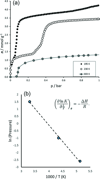 | ||
| Fig. 1 Adsorption of CO2 on MIL-53(Fe) to 1 bar. (a) Isotherms to 1 bar at 195 K, 230 K and 303 K. (b) Van't Hoff plot. | ||
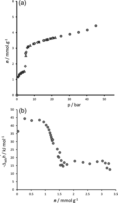 | ||
| Fig. 2 Adsorption of CO2 on MIL-53(Fe) at 303 K. (a) Isotherm repeated 5 times. (b) Enthalpies measured by calorimetry. | ||
The adsorption enthalpies are shown in Fig. 2b. Two main enthalpy regions can be distinguished which can be associated with the two filling regimes. For the first filling region, an enthalpy of around 42 kJ mol−1 is measured; however enthalpies in the region of the enthalpy of liquefaction (17 kJ mol−1) are measured during the second filling step. It is interesting to compare these results with those previously obtained with the MIL-53(Cr) and MIL-53(Al) structures.20,21 Indeed, the energies of adsorption in the NP form of these structures is estimated in the region of 41 kJ mol−1 in the aluminium solid and 45 kJ mol−1 in the chromium solid. In this work, such energies are associated with the filling of the INT structure (see below), in which half of the pores have the same opening as the NP form. Interesting though, lower energies are associated with the filling of the NP structure of MIL-53(Fe) (17 kJ mol−1) and this is more probably associated with the energy equally required to transform the structures from the INT to NP form. This behaviour is observed during the NP → LP transition in both MIL-53(Al) and MIL-53(Cr) and was again associated with the energy required for the structural transition.
3.2. CO2 localization by X-ray powder diffraction
As previously observed,11 the host MIL-53(Fe) undergoes structural swelling depending on the applied CO2 pressure. Starting from the “Closed Pore” (CP) form, three different phases can be observed (see Fig. 3). At room temperature and a pressure around 2 bar, corresponding to the middle of the first plateau seen in the adsorption isotherm, the “Intermediate” (INT) form was isolated. When reaching 10 bar at room temperature, a “Narrow Pore” (NP) form of the MIL-53(Fe)[nCO2] can be obtained, while maintaining the pressure at 10 bar and decreasing the temperature down to 220 K, the fully open “Large Pore” (LP) form was successfully isolated. Indexing of the three powder patterns [(INT), (NP) and (LP)] shows similarities with the unit cells previously reported for MIL-53(Fe)_int,22 MIL-53(Fe)[H2O] (ref. 23) and MIL-53(Fe)[2,6-lutidine,H2O].14 That led us to use directly the atomic coordinates of the frameworks of these three MIL-53 materials as starting models in the Rietveld refinements of the CO2-loaded structures. At this stage, RB and Rwp factors reached the following values for the (INT), (NP) and (LP) forms, respectively (RB = 0.058/RWP = 0.109, RB = 0.051/RWP = 0.096 and RB = 0.158/RWP = 0.191). The CO2 guest molecules were then localised by both difference Fourier map calculations and a direct space approach based on simulated annealing. During Rietveld refinements, 1,4-benzenedicarboxylate ions were treated as rigid bodies along with the CO2 molecules. The anisotropic line broadening effect was modelled by using spherical harmonics series. The final Rietveld refinements gave satisfactory crystal structure model indicators and profile factors (see Table 1). It should be noticed that the (LP) form was not obtained as a pure phase under the working conditions (T = 220 K, P = 10 bars) since this one coexists with the (NP) form, whose amount was estimated (from quantitative analysis using the Rietveld method) at only 2.56(4)% in weight. The thermal factor of CO2 molecules was arbitrarily fixed to 4 Å2 in the three structural models and it is clear that the errors on occupancy factors of guest molecules are underestimated. For the three filling states, the CO2/Fe ratio was refined and converged to a value of 0.22, 0.63 and 2.72 for the (INT), (NP) and (LP) form, respectively. The corresponding chemical formulae are therefore FeIII(OH)0.8F0.2[O2C–C6H4–CO2]·0.22CO2 for (INT), FeIII(OH)0.8F0.2[O2C–C6H4–CO2]·0.63CO2 for (NP) and FeIII(OH)0.8F0.2[O2C–C6H4–CO2]·2.72CO2 for (LP). These are written below using the notation MIL-53(Fe)[nCO2] to be consistent with our earlier notation of MIL-53(M)[guest] materials.14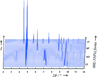 | ||
| Fig. 3 Adsorption of CO2 on MIL-53(Fe) followed by X-ray powder diffraction. Four different phases can be identified depending on the pressure and/or temperature (anhydrous CP, INT, NP and LP forms). | ||
The filling of the pores by the CO2 guest molecules leads to three different structures depending on pressure, for which the topology of the MOF skeleton is identical. The (INT) form crystallises in a triclinic unit cell (see Table 1). The crystallographic asymmetric unit contains two independent iron atoms and two OH/F groups on general positions, three carboxylate moieties [two on symmetry centres and one on general position] and one CO2 molecule also localised on a symmetry centre [occupancy of 0.881(6)]. As already observed in the metastable phase MIL-53(Fe)_int obtained during the dehydration of the MIL-53(Fe)[H2O],22 has two sets of tunnels with different sizes (described using the P![[1 with combining macron]](https://www.rsc.org/images/entities/char_0031_0304.gif) space group). The structure can be conveniently described in terms of iron–iron distances. Along the small diagonal of the largest lozenge (c-axis), the distances between two nearest iron(III) cations increase significantly from Fe2–Fe2 = 7.762 Å and Fe1–Fe1 = 7.499 Å in MIL-53(Fe)_int to Fe2–Fe2 = 8.127 Å and Fe1–Fe1 = 8.109 Å in the( INT) form, while the in the smallest lozenge, there are nearly no changes (Fe2–Fe2 = 5.723 Å and Fe1–Fe1 = 5.993 Å in MIL-53(Fe)_int to Fe2–Fe2 = 5.847 Å and Fe1–Fe1 = 5.846 Å in the( INT) form). It is obvious that the smallest tunnels remain empty during the first stage of CO2 uptake, and that the guests can only lie in half of the channels, the largest ones (see Fig. 4). The difference Fourier map calculations reveal unambiguously the exact position of the CO2 molecule located at the centre of the largest pores, whereas no electron density was observed in the smallest ones. Analysis of the position of the CO2 molecules led us to understand the nature of the host–guest and guest–guest interactions. Contrary to what has been observed in MIL-53(Sc)-int in which the CO2 molecules are aligned with the long diagonal of the rhombic cross section of the channel,13 in our case the CO2 molecules are stacked along the a-axis in such a way that they are (i) almost parallel to each other and (ii) nearly parallel to the inorganic chains. However, a small tilt of the CO2 molecule with the inorganic chain is observed in order to favour interactions between the oxygen atom (O3) of the guest molecule and the OH/F group (O1) of the two opposite inorganic chains in the direction of the small diagonal of the lozenge with a distance d(O3⋯O1) = 2.83(2) Å. All hydroxyl groups of the filled tunnels are then involved in hydrogen bonding with the guest molecule but there is no interaction between the CO2 molecules themselves d(O3⋯O3) = 4.793(3) Å.
space group). The structure can be conveniently described in terms of iron–iron distances. Along the small diagonal of the largest lozenge (c-axis), the distances between two nearest iron(III) cations increase significantly from Fe2–Fe2 = 7.762 Å and Fe1–Fe1 = 7.499 Å in MIL-53(Fe)_int to Fe2–Fe2 = 8.127 Å and Fe1–Fe1 = 8.109 Å in the( INT) form, while the in the smallest lozenge, there are nearly no changes (Fe2–Fe2 = 5.723 Å and Fe1–Fe1 = 5.993 Å in MIL-53(Fe)_int to Fe2–Fe2 = 5.847 Å and Fe1–Fe1 = 5.846 Å in the( INT) form). It is obvious that the smallest tunnels remain empty during the first stage of CO2 uptake, and that the guests can only lie in half of the channels, the largest ones (see Fig. 4). The difference Fourier map calculations reveal unambiguously the exact position of the CO2 molecule located at the centre of the largest pores, whereas no electron density was observed in the smallest ones. Analysis of the position of the CO2 molecules led us to understand the nature of the host–guest and guest–guest interactions. Contrary to what has been observed in MIL-53(Sc)-int in which the CO2 molecules are aligned with the long diagonal of the rhombic cross section of the channel,13 in our case the CO2 molecules are stacked along the a-axis in such a way that they are (i) almost parallel to each other and (ii) nearly parallel to the inorganic chains. However, a small tilt of the CO2 molecule with the inorganic chain is observed in order to favour interactions between the oxygen atom (O3) of the guest molecule and the OH/F group (O1) of the two opposite inorganic chains in the direction of the small diagonal of the lozenge with a distance d(O3⋯O1) = 2.83(2) Å. All hydroxyl groups of the filled tunnels are then involved in hydrogen bonding with the guest molecule but there is no interaction between the CO2 molecules themselves d(O3⋯O3) = 4.793(3) Å.
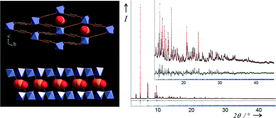
The (NP) form crystallises in a monoclinic unit cell (see Table 1). The crystallographic asymmetric unit contains one independent iron atom (on a symmetry centre), one OH/F group (on the twofold axis) and one carboxylate moiety (also on a symmetry centre). The disordered CO2 molecule was localised on general position with occupancy of 0.313(2). Contrary to the (INT) form, all of the tunnels are equivalent and now filled by the CO2 guest molecule at the centre of the pores. Along the small diagonal of the largest lozenge (b-axis), the distance between two nearest iron(III) cations is Fe–Fe = 8.251 Å in the (NP) form (see Fig. 5). This distance is close to that previously observed in the largest filled tunnel in the (INT) form and much larger than the one seen in MIL-53(Fe)[H2O] (Fe–Fe = 7.643 Å) as expected taking into account the kinetic diameter of both different guest molecules.23 In this (NP) form, the CO2 molecules are closely aligned with the long diagonal of the rhombic cross section of the channels and stacked along the c-axis in such a way that they are (i) almost parallel to each other and (ii) nearly perpendicular to the inorganic chains. This stacking seen in the (NP) form is in closed agreement with the one found from ab initio molecular dynamics simulations for MIL-53(Sc)-int, even if only half the pores were filled by CO2 in that case.13 Half of the OH/F groups (O1) now interact with only one oxygen atom of the CO2 guest molecule (O3) with a distance d(O3⋯O1) = 2.923(4) Å. Like in the (INT) form, no guest–guest interactions can be identified with the closest distance d(O3⋯O3) = 4.659(1) Å.
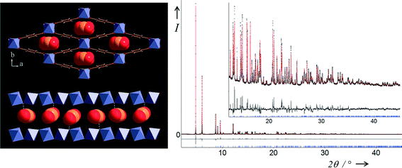 | ||
| Fig. 5 Two views of the structure of MIL-53(Fe)[0.63CO2] (top left) in the ab plane showing stacked CO2 molecules within all the lozenge-shaped channels and (bottom left) view of a single channel in the almost perpendicular direction. Final Rietveld plot (right) for MIL-53(Fe)[0.63CO2] from X-ray powder diffraction data measured at RT and 10 bar. Legend as Fig. 4. | ||
The (LP) form crystallises in an orthorhombic unit cell (see Table 1). The crystallographic asymmetric unit contains one independent iron atom sited on the 4d Wyckoff position, one OH/F group (4e) and one carboxylate moiety (centred on 4b) and two disordered independent CO2 molecules, the first one being centered on 8h (occupancy of 0.5) and the second one on general position [occupancy of 0.430(2)]. In that form, a huge increase of the small diagonal of the lozenge has been observed (Fe–Fe = 13.638 Å) suggesting drastic changes in the amount of CO2 inside the pores in comparison with the two previous forms (see Fig. 6). This is reminiscent of both the structure of the superhydrated chromium form MIL-53(Cr)[6.2H2O] (Fe–Fe = 15.245 Å)24 and the structure of the MIL-53(Fe)[2,6-lutidine,H2O] (Fe–Fe = 14.392 Å).14 In the (LP) form, the two CO2 molecules are no longer localised at the centre of the pores: the first type (named A) are now located either side of the large diagonal of the lozenge, while the second type (named B) are sited either side of the small diagonal, which leads to a split of all CO2 sites. This can explain the nmax value (see Table 1) corresponding to the maximum quantity of CO2 able to fit in each MIL-53(Fe)[nCO2]. Indeed, knowing that the nmax values for the two corresponding (INT) and (NP) forms are 0.25 and 1 respectively, and taking into account that (i) all channels are filled and (ii) all CO2 sites are split in the (LP) form, this leads to a nmax value of 3 (2 × 2 × 0.25 + 2 × 1) for this latter form. The A molecules adopt almost the same orientation as in the (INT) form: they are stacked along the inorganic chains (c-axis) and parallel to these chains, and they are strictly parallel to each other. The B molecules adopt almost the same orientation as in the (NP) form: they are mostly aligned with the long diagonal of the rhombic cross section of the channel and stacked along the c-axis in such a way that (i) the torsion angle between two adjacent CO2 molecules is about 30° and that they are (ii) nearly perpendicular to the inorganic chains. Contrary to the (INT) form where each CO2 molecule is sharing two OH/F groups of two adjacent inorganic chains, all the OH/F groups (O1) are now involved in hydrogen bonding but with only one oxygen atom of the A molecule (O2) with a distance d(O2⋯O1) = 3.014(6) Å. There is no interaction between the A molecules themselves d(O2⋯O3) = 4.578(1) Å. However, the carbon atom of this A molecule is in close contact with one oxygen atom of two B molecules [d(C2⋯O5) = 3.239(1) Å and d(C2⋯O5) = 3.200(1) Å)]. This short contact agrees well with the closest distance between two adjacent molecules found in the solid CO2 structure, where d(C⋯O) = 3.107(1) Å even if the orientation is different: in the solid, CO2 molecules arrange themselves in successive planes but pointing in the opposite direction relative to each other.25 Therefore, the neighboring B molecules are closely packed along the long diagonal of the lozenge-shaped tunnels with some evidence of guest–guest interaction.
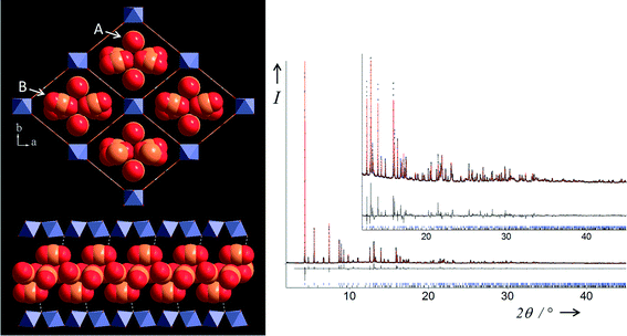 | ||
| Fig. 6 Two views of the structure of MIL-53(Fe)[2.72CO2] (top left) in the ab plane showing stacked CO2 molecules (two types, labelled A and B) within all the lozenge-shaped channels and (bottom left) view of a single channel in the almost perpendicular direction. Final Rietveld plot (right) for MIL-53(Fe)[2.72CO2] from X-ray powder diffraction data measured at 220 K and 10 bar. Legend as Fig. 4. The blue tickmarks (upper) indicate Bragg peak positions of the LP form (97.44(4)% weight) and the black ones (lower) those of the NP form observed as an impurity (2.56(4)% weight). | ||
4. Conclusions
We have determined accurate information regarding the location of adsorbent molecules in one of the prototypical flexible metal–organic frameworks. Although studies of CO2 adsorption in various forms of MIL-53 have previously been reported and the location of the guest molecules determined from simulation, this study is the only one to locate accurately from powder diffraction the positions of the guest molecules at various stages of the multi-step adsorption process. The nmax values for the two corresponding (INT) and (NP) forms are in good agreement with the CO2 uptake seen on the two plateau regions. Like the Sc3+ analogue of the material (one of the rare cases where guest location has been reported),13 the Fe3+ form takes up CO2 at low pressures to give a structure in which alternate channels are filled, but in order to favour interactions between the oxygen atom of the guest molecule and the framework OH/F groups the CO2 molecules are orientated differently. At higher pressure all pores are occupied and filled by the CO2 guest molecule at their centres: again the predominant interaction appears to be with the framework OH/F groups rather than guest–guest interactions. At the highest pressure applied the CO2 molecules are no longer found at the centre of the pores: one type is located either side of the large diagonal of the lozenge, while a second type is sited either side of the small diagonal. Here guest–guest interactions, similar to seen in solid CO2 are also observed. In this form the MIL-53 structure is fully open and the CO2 capacity is maximised.Acknowledgements
We thank the ESRF for beamtime on ID31. We are grateful to Dr Andy Fitch and Dr Adrian Hill of the ESRF for their assistance with running the experiments on ID31. Some of the authors would like to acknowledge the financial support of the European Community STREP project “DeSANNS” (no. FP6-SES6-020133).References
- Functional Metal-Organic Frameworks: Gas Storage, Separation and Catalysis, ed. M. Schröder, Springer-Verlag Berlin Heidelberg, 2010 CrossRef CAS PubMed; Metal-Organic Frameworks: Applications from Catalysis to Gas Storage, Separation and Catalysis, ed. D. Farrusseng, Wiley-VCH Verlag, Weinheim, 2011 CrossRef CAS PubMed; S. T. Meek, J. A. Greathouse and M. D. Allendorf, Adv. Mater., 2011, 23, 249 CrossRef CAS PubMed; H. Furukawa, K. E. Cordova, M. O'Keeffe and O. M. Yaghi, Science, 2013, 341, 974 CrossRef PubMed.
- J.-R. Li, Y. Ma, M. C. McCarthy, J. Sculley, J. Yu, H.-K. Jeong, P. B. Balbuena and H.-C. Zhou, Coord. Chem. Rev., 2011, 255, 1791 CrossRef CAS PubMed; Y. S. Bae and R. Q. Snurr, Angew. Chem., Int. Ed., 2011, 50, 11586 CrossRef PubMed; J. Liu, P. K. Thallapally, B. P. McGrail, D. R. Brown and J. Liu, Chem. Soc. Rev., 2012, 41, 2308 RSC; Y. Liu, Z. U. Wang and H.-C. Zhou, Greenhouse Gases: Sci. Technol., 2012, 2, 239 CrossRef; B. Li, H. L. Wang and B. L. Chen, Chem. – Asian J., 2014, 9, 1474 CrossRef PubMed; Z. J. Zhang, Y. G. Zhao, Q. H. Gong, Z. Li and J. Li, Chem. Commun., 2013, 49, 653 RSC.
- D. Britt, H. Furukawa, B. Wang, T. G. Glover and O. M. Yaghi, Proc. Natl. Acad. Sci. U. S. A., 2009, 106, 20637 CrossRef CAS PubMed.
- H. Wu, Y. S. Chua, V. Krungleviciute, M. Tyagi, P. Chen, T. Yildirim and W. Zhou, J. Am. Chem. Soc., 2013, 135, 10525 CrossRef CAS PubMed.
- C. H. Lau, R. Babarao and M. R. Hill, Chem. Commun., 2013, 49, 3634 RSC.
- J. W. Yoon, S. H. Jhung, Y. K. Hwang, S. M. Humphrey, P. T. Wood and J. S. Chang, Adv. Mater., 2007, 19, 1830 CrossRef CAS.
- S. Kitagawa and K. Uemura, Chem. Soc. Rev., 2005, 34, 109 RSC; S. Bureekaew, S. Shimomura and S. Kitagawa, Sci. Technol. Adv. Mater., 2008, 9 Search PubMed; A. Schneemann, V. Bon, I. Schwedler, I. Senkovska, S. Kaskel and R. A. Fischer, Chem. Soc. Rev., 2014, 43, 6062 RSC.
- G. Férey and C. Serre, Chem. Soc. Rev., 2009, 38, 1380 RSC.
- F. Millange, C. Serre and G. Férey, Chem. Commun., 2002, 822 RSC.
- F. Nouar, T. Devic, H. Chevreau, N. Guillou, E. Gibson, G. Clet, M. Daturi, A. Vimont, J. M. Grenèche, M. I. Breeze, R. I. Walton, P. L. Llewellyn and C. Serre, Chem. Commun., 2012, 48, 10237 RSC; M. I. Breeze, G. Clet, B. C. Campo, A. Vimont, M. Daturi, J.-M. Grenèche, A. J. Dent, F. Millange and R. I. Walton, Inorg. Chem., 2013, 52, 8171 CrossRef CAS PubMed.
- T. Devic, F. Salles, S. Bourrelly, B. Moulin, G. Maurin, P. Horcajada, C. Serre, A. Vimont, J.-C. Lavalley, H. Leclerc, G. Clet, M. Daturi, P. L. Llewellyn, Y. Filinchuk and G. Férey, J. Mater. Chem., 2012, 22, 10266 RSC.
- S. Couck, E. Gobechiya, C. E. A. Kirschhock, P. Serra-Crespo, J. Juan-Alcaniz, A. M. Joaristi, E. Stavitski, J. Gascon, F. Kapteijn, G. V. Baron and J. F. M. Denayer, ChemSusChem, 2012, 5, 740 CrossRef CAS PubMed; L. Chen, J. P. S. Mowat, D. Fairen-Jimenez, C. A. Morrison, S. P. Thompson, P. A. Wright and T. Düren, J. Am. Chem. Soc., 2013, 135, 15763 CrossRef PubMed.
- J. P. S. Mowat, V. R. Seymour, J. M. Griffin, S. P. Thompson, A. M. Z. Slawin, D. Fairen-Jimenez, T. Düren, S. E. Ashbrook and P. A. Wright, Dalton Trans., 2012, 41, 3937 RSC.
- F. Millange, N. Guillou, M. E. Medina, G. Férey, A. Carlin-Sinclair, K. M. Golden and R. I. Walton, Chem. Mater., 2010, 22, 4237 CrossRef CAS.
- P. L. Llewellyn, P. Horcajada, G. Maurin, T. Devic, N. Rosenbach, S. Bourrelly, C. Serre, D. Vincent, S. Loera-Serna, Y. Filinchuk and G. Férey, J. Am. Chem. Soc., 2009, 131, 13002 CrossRef CAS PubMed.
- Topas V4.2: General Profile and Structure Analysis Software for Powder Diffraction Data, Bruker AXS Ltd, 2008 Search PubMed.
- G. De Weireld, M. Frere and R. Jadot, Meas. Sci. Technol., 1999, 10, 117 CrossRef CAS.
- A. Ghoufi, L. Gaberova, J. Rouquerol, D. Vincent, P. L. Llewellyn and G. Maurin, Microporous Mesoporous Mater., 2009, 119, 117 CrossRef CAS PubMed.
- P. L. Llewellyn and G. Maurin, C. R. Chim., 2005, 8, 283 CrossRef CAS PubMed.
- S. Bourrelly, P. L. Llewellyn, C. Serre, F. Millange, T. Loiseau and G. Férey, J. Am. Chem. Soc., 2005, 127, 13519 CrossRef CAS PubMed.
- N. A. Ramsahye, G. Maurin, S. Bourrelly, P. L. Llewellyn, C. Serre, T. Loiseau, T. Devic and G. Férey, J. Phys. Chem. C, 2008, 112, 514 CAS.
- F. Millange, N. Guillou, R. I. Walton, J.-M. Grenèche, I. Margiolaki and G. Férey, Chem. Commun., 2008, 4732 RSC.
- N. Guillou, R. I. Walton and F. Millange, Z. Kristallogr. - Cryst. Mater., 2010, 225, 552 CrossRef CAS.
- N. Guillou, F. Millange and R. I. Walton, Chem. Commun., 2011, 47, 713 RSC.
- A. Simon and K. Peters, Acta Crystallogr., Sect. B: Struct. Crystallogr. Cryst. Chem., 1980, 36, 2750 CrossRef.
Footnote |
| † Electronic supplementary information (ESI) available: Crystal structure data in cif format. See 10.1039/c4ce01393j |
| This journal is © The Royal Society of Chemistry 2015 |

