
 Open Access Article
 This Open Access Article is licensed under a
 Creative Commons Attribution 3.0 Unported Licence
Efficient orange organic light-emitting diodes employing a central aniline bridged multiresonant thermally activated delayed fluorescence emitter†
Sen Wu‡
a,
Ya-Nan
Hu‡
b,
Jingxiang
Wang
a,
Dianming
Sun
*a,
Kai
Wang
 b,
Xiao-Hong
Zhang
*bc and
Eli
Zysman-Colman
*a
b,
Xiao-Hong
Zhang
*bc and
Eli
Zysman-Colman
*a
aOrganic Semiconductor Centre, EaStCHEM School of Chemistry, University of St Andrews, St Andrews, Fife KY16 9ST, UK. E-mail: eli.zysman-colman@st-andrews.ac.uk; sd235@st-andrews.ac.uk; Fax: +44-1334 463808; Tel: +44-1334 463826
bInstitute of Functional Nano & Soft Materials (FUNSOM), Joint International Research Laboratory of Carbon-Based Functional Materials and Devices, Soochow University, Suzhou, Jiangsu 215123, P. R. China. E-mail: xiaohong_zhang@suda.edu.cn
cJiangsu Key Laboratory of Advanced Negative Carbon Technologies, Soochow University, Suzhou, 215123, Jiangsu, P. R. China
First published on 3rd April 2024
Abstract
Multiresonant thermally activated delayed fluorescence (MR-TADF) compounds are attractive for use in organic light-emitting diodes as they show narrowband emission, are bright, and can harvest both singlet and triplet excitons for the emission of light. Reflected in the paucity of examples of orange-to-red emitters, developing MR-TADF emitters that emit beyond the green remains an outstanding materials design challenge. In this work, we report one of the first carbonyl-based orange MR-TADF emitters, DDiKTa-A, which is based on the dimerization of the sky-blue emitting DiKTa through a central aniline bridge. DDiKTa-A emits at λPL of 562 nm and has high photoluminescence quantum yield of 92% in 2 wt% doped films in mCP. DDiKTa-A exhibits temperature dependent steady-state photoluminescence in 2-MeTHF, acting as an indirect indicator of the polarity of the medium. The OLEDs with DDiKTa-A showed an EQEmax of 20.3%, but with significant efficiency roll-off (EQE100 of 13.2%). The EQEmax was improved, and the efficiency roll-off mitigated by incorporating an assistant dopant, 4CzIPN, within the emissive layer of the device. The hyperfluorescence device showed an EQEmax of 24.3%, which decreased to 22.5 and 14.6% at 100 and 1000 cd m−2, respectively.
Introduction
Multiresonant thermally activated delayed fluorescence (MR-TADF) materials show significant potential as emitters in organic light-emitting diodes (OLEDs) as they have the requisite narrowband emission to produce the required saturated colors for high-definition displays.1–5 Unlike conventional donor–acceptor (D–A) TADF emitters, the structural rigidity inherent in most MR-TADF emitters reduces geometric relaxation upon excitation, resulting in a narrowband emission. The disposition of electron-rich and electron-deficient groups within the polycyclic aromatic hydrocarbon skeleton produces an emissive excited state of short-range charge-transfer (SRCT) character where there is a small exchange integral reflected in the moderately small singlet–triplet energy gap, ΔEST, that enables TADF.To date, numerous MR-TADF emitters have been developed, some of which produce OLEDs that show fantastic performance including examples where the maximum external quantum efficiency (EQEmax) exceeds 40%.6 There are now many reported blue and green MR-TADF OLEDs including examples that approach the B.T. 2020 industry standard for green7–11 and blue emission.12–15 However, examples of orange/red MR-TADF OLEDs remain relatively rare due to the challenges in emitter design to red-shift the emission of the emitters.6 There are currently two primary methods for shifting the emission to the red: (1) Enhancing the donor and acceptor strength by constructing systems with electron-accepting (A) and donating atoms (D) in A-para-A and D-para-D regiochemistry;16–19 (2) Decorating the MR-TADF core with donor or acceptor substituents to tune the energy of the emissive core;20,21 note that the use of too strong donors or acceptors results in the excited state being of long-range charge transfer (LRCT) character, resulting in less bright and broader emission. Dimerization of MR-TADF emitters is a distinct strategy for realizing red-shifted emission via extending the conjugation area. To date, there are only limited samples that have been reported based on this latter strategy.22–24 Our group reported the first example of a dimeric MR-TADF emitter by connecting two DiKTa units (aka QAO or QAD)25–27 through a single bond in DDiKTa (Scheme S1, ESI†).22 The photoluminescence (PL) was observed to red-shift from 451 nm for DiKTa to 470 nm for DDiKTa in toluene. Yasuda and co-workers reported another two isomeric MR-TADF dimers formed by tethering two MR-TADF fragments with different regiochemistry, para-B-π-B for p-CzB and para-N-π-N for m-CzB, as shown in Scheme S1 (ESI†).23 Compared to DtBuCzB (λPL = 489 nm), p-CzB and m-CzB emit at 504 and 515 nm in toluene, representing a modest red-shift of their PL.28 The devices with p-CzB and m-CzB showed EQEmax of 20.2 and 23.5%, respectively. Lan and co-workers reported another two MR-TADF dimeric emitters, DBF-DBN and DBT-DBN (Scheme S1, ESI†).24 The OLEDs with DBF-DBN and DBT-DBN emitted at 514 and 516 nm and showed EQEmax of 21.5 and 31.3%, respectively. Each of these three reports documents a red-shifted emission of the dimeric emitters compared to their monomeric counterparts; however, the emission is in the green region and no example to date demonstrates that this strategy can be used to push the emission further to the red.
Here, we report the emitter DDiKTa-A, a compound that contains two DiKTa units bridged by a central aniline (Fig. 1). Using this design based on a synergy between a compound containing para-N-π-N conjugation and two emissive luminophores leads to a strong red-shift of the emission from blue (λPL = 453 nm) for DiKTa29 to yellow (λPL = 551 nm) for DDiKTa-A in toluene solution. The emission of DDiKTa-A shows a significant temperature sensitivity in 2-MeTHF, reflected in a color change from 566 to 638 nm across a temperature range from 123 to 298 K. In 2 wt% doped films in 1,3-bis(N-carbazolyl)benzene (mCP), DDiKTa-A emits at 562 nm, has a high photoluminescence quantum yield, ΦPL, of 92%, and a delayed lifetime, τd, of 279 μs. The OLEDs with DDiKTa-A showed an EQEmax of 20.3% at λEL of 573 nm but with a severe efficiency roll-off (EQE100 of 13.2%). To tackle the observed efficiency roll-off, hyperfluorescence (HF) devices incorporating 4CzIPN as the assistant dopant were fabricated and showed much improved performance, with an enhanced EQEmax of 24.3% and a reduced efficiency roll-off with EQE100 of 22.5% and EQE1000 of 14.6% at λEL of 574 nm.
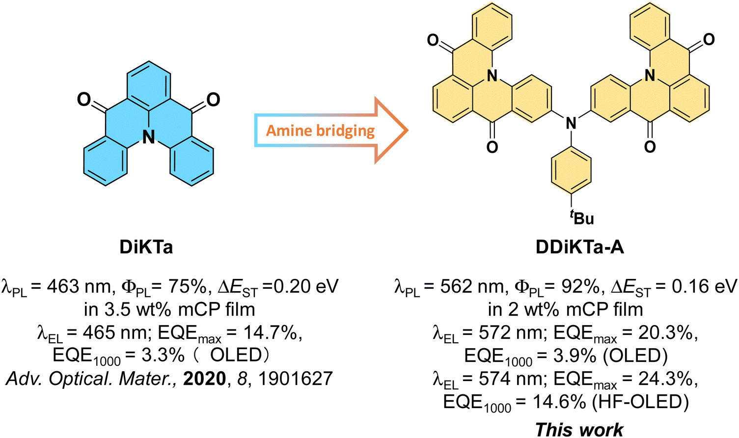 | ||
| Fig. 1 Chemical structures, photophysical and device properties of DiKTa and DDiKTa-A. | ||
Results and discussion
DDiKTa-A was obtained in one step from DiKTa-Br22via a two-fold palladium-catalysed Buchwald-Hartwig cross-coupling reaction with 4-tert-butylaniline (Scheme S1, ESI†). DDiKTa-A was purified by column chromatography and then by gradient-temperature vacuum sublimation. The identity and purity of DDiKTa-A was assessed using a combination of 1H & 13C nuclear magnetic resonance spectroscopy, high-resolution mass spectrometry, melting point determination, high-pressure liquid chromatography and elemental analysis (Fig. S1–S5, ESI†).The optoelectronic properties of DDiKTa-A were firstly modelled using a combination of density functional theory (DFT) and wavefunction-based methods as the latter have been previously shown to accurately predict the excited state energies of MR-TADF compounds, including the structurally related DiDOBNA-N.15,30 The geometry in the ground state and the HOMO/LUMO levels were calculated at the PBE0/6-31G(d,p) level. As shown in Fig. 2a, the LUMO is mostly localized on the DiKTa moieties, while the HOMO is delocalized across the whole molecule. Compared to the HOMO/LUMO levels of DiKTa (−6.20/−2.23 eV)31 and DDiKTa (−6.04/−2.34) the HOMO of DDiKTa-A is significantly destabilized while the LUMO is effectively unchanged (−5.39/−2.24 eV). The resulting energy gap (ΔE) of 3.15 eV is smaller than those of DiKTa (3.97 eV) and DDiKTa (3.70 eV).32 As a result of the amine, there is considerable conformational flexibility in DDiKTa-A, reflected in the differences in geometry between the ground and singlet excited state (RMSD value of 0.2757, Fig. S6, ESI†), which will likely lead to a broad emission similar to that observed for DiDOBNA-N.15 The energies of the low-lying singlet and triplet excited states were calculated at the SCS-ADC(2)/cc-pVDZ level (Fig. S2b, ESI†).33,34 The difference density plots reveal the expected alternating pattern of increasing and decreasing electron density in the excited states as compared to the ground state, reflective of states of SRCT character. The plots also show that the electron density is delocalized across both DiKTa moieties and the bridging nitrogen atom. The distribution pattern for the S2/T2 is similar to that of the S1/T1 states but does not involve as significantly the bridging aniline. The S1 energy level is 3.08 eV, which is stabilized compared to that of DDiKTa of 3.39 eV and DiKTa of 3.46 eV, indicating that the emission should be lower in energy. The calculated ΔEST of 0.22 eV is smaller than the predicted value of 0.27 eV for both DiKTa and DDiKTa. The SOC matrix element (SOCME) between S1 and T1 at the T1-optimized geometry (Fig. S7, ESI†) was calculated to be 0.49 cm−1 while that from T2 to S1 was 0.44 cm−1 (Fig. S8, ESI†).
 | ||
| Fig. 2 (a) Distributions of the frontier molecular orbitals (isovalue: 0.02) of DDiKTa-A, calculated in the gas phase at the PBE0/6-31G(d,p) level; (b) difference density plots (isovalue: 0.001) of S1/S2 and T1/T2 excited states (calculated in the gas phase at the SCS-ADC(2)/cc-pVDZ level) for DDiKTa-A. f is the oscillator strength. | ||
The electrochemical properties were investigated using cyclic voltammetry (CV) and differential pulse voltammetry (DPV) in dichloromethane (Fig. S10, ESI†). The CV of DDiKTa-A shows reversible oxidation and reduction waves. The oxidation (Eox) and reduction potentials (Ered), determined from the respective peaks in the DPV, are 0.98 and −1.32 eV versus a saturated calomel electrode (SCE). The corresponding HOMO and LUMO levels are calculated to be −5.32 and −3.02 eV. The HOMO is destabilized while the LUMO is of similar energy to those of DiKTa (−6.12 eV/−3.00 eV),29 reflecting the predictions from DFT.
The UV-vis absorption spectrum of DDiKTa-A in dilute toluene solution (10−5 M) at room temperature is shown in Fig. 3a. There are three identifiable absorption bands with peaks of 323, 397 and 473 nm, which generally match with the simulated absorption spectra (Fig. S9, ESI†). The two intense, higher energy bands (ε of 3.0 × 10⁴ and 1.6 × 10⁴ M−1 cm−1, respectively) are associated, respectively, with π–π* transitions across the DiKTa backbone (λabs = 334 nm, ε = 3.5 × 10³ M−1 cm−1)25 and the whole skeleton, based on an analysis of the TDA-DFT calculations (Fig. S9, ESI†). The absorption band at 474 nm (ε = 1.2 × 10⁴ M−1 cm−1) is associated with the characteristic SRCT state and is both red-shifted and weaker compared to the SRCT band of DiKTa (λabs = 435 nm with ε = 2.1 × 10⁴ M−1 cm−1), likely implicating that this state in DDiKTa-A contains an admixture of SRCT and LRCT character.25 The steady-state photoluminescence (PL) spectrum in toluene of DDiKTa-A is broad, having a peak at λPL of 551 nm and a FWHM of 76 nm. This emission is significantly red-shifted and broader compared to that of DDiKTa (λPL = 470 nm, FWHM = 47 nm), of DiKTa (λPL = 453 nm, FWHM = 27 nm), and of DiDOBNA-N (λPL = 426 nm, FWHM = 43 nm).25,32 The broader emission is attributed to combination of an emissive excited state possessing an admixture of SRCT and LRCT character and a conformationally flexible structure. Distinct from that observed for these three compounds, there is a more significant positive solvatochromism (Fig. S11, ESI†) that is consistent with of an emissive excited state that possesses mixed SRCT and LRCT character.
 | ||
| Fig. 3 (a) Absorption and steady-state photoluminescence (SS PL) spectra in toluene at RT, λexc = 340 nm. (Inset: photo of DDiKTa-A in toluene and irradiated with a UV torch, λexc = 365 nm.) (b) The SS PL and phosphorescence spectra (1–10 ms in 2-MeTHF glass at 77 K), λexc = 340 nm. | ||
The energies of the S1 and T1 states were determined from the onsets of the steady-state photoluminescence (SS PL) spectra and delayed emission in 2-MeTHF glass at 77 K (Fig. 3b). The extracted S1 and T1 energies are 2.34 and 2.17 eV, respectively, leading to a ΔEST of 0.17 eV, which is smaller than that of DiKTa (0.20 eV), DDiKTa (0.21 eV), and DIDOBNA-N (0.22 eV). The time-resolved PL (TR PL) decays in toluene are shown in Fig. S12b (ESI†). The emission decays with biexponential kinetics, with prompt lifetime, τp, of 16.3 ns and delayed lifetime, τd, of 41.0 μs under N2; the delayed emission was quenched upon exposure to air (Fig. S12a, ESI†). The ΦPL decreases from 44 to 36% upon exposure to air. The inferred kinetics rate constants are summarized in Table S2 (ESI†) and the rate constant for RISC, kRISC, is 1.63 × 10⁴ s−1. Notably, no delayed lifetime in toluene solution was observed for DiKTa, DDiKTa, and DIDOBNA-N.
As shown in Fig. 4, the SS PL of DDiKTa-A exhibits a temperature dependence in 2-MeTHF solution (123–298 K). DDiKTa-A shows a structureless orange emission at 577 nm at RT and when the temperature decreases to 163 K there is a gradual red-shift of the emission to 638 nm. This phenomenon can be attributed to the increased dielectric constant of 2-MeTHF upon cooling, which stabilizes the LRCT state of DDiKTa-A.35–37 When the temperature is close to the glass transition temperature of 2-MeTHF (131–142 K)38 the emission blue-shifts, ultimately reaching 566 nm at 123 K. This shift is attributed to the longer geometry relaxation time in frozen 2-MeTHF.35 Importantly, this observation suggests that the red-shifted emission is a result of the sensitivity of the singlet state to the polarity of the environment, rather than aggregation during the cooling process.
 | ||
| Fig. 4 (a) Images showing samples in 2-MeTHF irradiated with a UV torch at different temperatures. (b) Temperature-dependent steady-state PL spectra in 2-MeTHF, λexc = 365 nm. (c) CIE diagram associated with steady-state PL spectra in (b) as a function of temperature. | ||
To explore the potential of DDiKTa-A as an emitter in OLEDs, we turned our attention to assessing the photophysical properties in mCP thin films, as this host has a suitably high triplet energy (ET = 3 eV)39 to confine the excitons onto the emitter (Fig. 5). We first explored the dependence of both the SS PL and ΦPL of DDiKTa-A on the doping concentration in mCP (Fig. S13, ESI†). Under N2, the ΦPL decreased from 92 to 74% upon increasing the doping concentration from 2 to 10 wt% in mCP, while the emission red-shifted from 562 to 588 nm, indicating that the emitter tends to aggregate and that these aggregates quench the emission. Therefore, using only the 2 wt% films, we next screened the properties in two other high triplet energy hosts, PPT and DPEPO (Fig. S14, ESI†). In both phosphine oxide-based hosts, the 2 wt% films emit at around 600 nm while the ΦPL are 69 and 50%, respectively. The observed red-shifting of the emission from orange in mCP (λPL = 562 nm, FWHM = 75 nm) to red (λPL = 600 nm, FWHM = 102 nm) in these two hosts can be attributed to the increased stabilization of the LRCT state with increasing host polarity. Due to the high ΦPL and narrower emission in the 2 wt% doped films in mCP, we carried out the subsequent photophysical studies using this film. The ΔEST of DDiKTa-A in this film is 0.16 eV (Fig. S15, ESI†), which is of similar magnitude to that measured in 2-MeTHF glass. The emission is quenched in the presence of air, dropping from a ΦPL of 92 to 80%. There is the characteristic temperature dependence of the delayed emission that is indicative of TADF (Fig. S16, ESI†). The TR PL decay at RT shows multiexponential kinetics under vacuum, the average τP and τd are 15.1 ns and 279 μs, The kinetics rate constants for the 2 wt% doped films in mCP are collected in Table S2 (ESI†) and the kRISC is 1.9 × 10⁴ s−1 for DDiKTa-A, which is similar to that determined in 2 wt% doped film in mCP for DiKTa (kRISC = 2.5 × 10⁴ s−1).31 A summary of the photophysical properties of the 2 wt% doped films in mCP is provided in Table 1.
 | ||
| Fig. 5 (a) Steady-state PL spectra, λexc = 340 nm (Inset: photo of 1 wt% doped film of DDiKTa-A in mCP and irradiated with a UV torch, λexc = 365 nm.) and (b) time-resolved PL decays (inset is the PL decay of prompt component measured by TCSPC method), under vacuum and air of 2 wt% DDiKTa-A in mCP doped film, λexc = 375 nm. | ||
| Emitters | Φ PL/%a | λ PL/nmb | FWHM/nmc | S1/eVd | T1/eVe | ΔEST/eVf | τ p/nsg | τ d/μsg | k RISC/104 s−1 |
|---|---|---|---|---|---|---|---|---|---|
| a The ΦPL was measured using an integrating sphere under nitrogen (λexc = 340 nm). b Obtained at 298 K, λexc = 340 nm. c Full-width at half-maximum. d Obtained from the onset of the steady-state PL spectrum at 77 K. e Obtained from the onset of the delayed emission spectrum (1–10 ms) at 77 K (λexc = 340 nm). f ΔEST = E(S1) – E(T1). g Measured at 300 K under vacuum, λexc = 379 nm. | |||||||||
| DDiKTa-A | 92 | 562 | 75 | 2.36 | 2.20 | 0.16 | 15.1 | 279 | 1.91 |
| DiKTa 31 | 46 | 467 | 46 | 2.75 | 2.55 | 0.2025 | 4.8 | 242 | 2.52 |
Device characterization
Vacuum-deposited OLEDs with DDiKTa-A were firstly fabricated with the device structure of: ITO/TAPC (35 nm)/TCTA (10 nm)/CzSi (10 nm)/x wt% emitter: mCP/(20 nm)/TmPyPB (40 nm)/LiF (1 nm)/Al (100 nm), where indium tin oxide (ITO) is the anode, 4,4′-cyclohexylidenebis[N,N-bis(4-methylphenyl) benzenamine] (TAPC) acts as the hole-transport layer. 9-(4-tert-butylphenyl)-3,6-bis(triphenylsilyl)-9H-carbazole (CzSi) is used to block excitons, 1,3,5-tri(m-pyridin-3-ylphenyl)benzene (TmPyPB) acts as the electron-transporting material, and LiF modifies the work function of the aluminum cathode. The device stacks and chemical structures of the materials are shown in Fig. 6b. The device performance is summarized in Fig. 6 and Fig. S17–S21 (ESI†) and Table 2. | ||
| Fig. 6 a) Energy level diagram of materials employed in the devices. (b) Molecular structures of materials used in the devices. (c) Current density and luminance versus voltage characteristics for the devices. (d) External quantum efficiency versus luminance curves for the devices. (e) Electroluminescence spectra of the devices. | ||
| Emissive layer | V on /V | λ EL/nm | FWHMb/nm | CIE (x, y) | L max /cd m−2 | EQEmax/100/1![[thin space (1/6-em)]](https://www.rsc.org/images/entities/char_2009.gif) 000d/% 000d/% |
|---|---|---|---|---|---|---|
|
a Turn on voltage, recorded at 1 cd m−2.
b Full width at half-maximum of the electroluminescence spectrum.
c Maximum luminance.
d Maximum external quantum efficiency/EQE at 100 cd m−2/EQE at 1000 cd m−2.
|
||||||
| DDiKTa-A/mCP | 3.6 | 572 | 69 | 0.49, 0.50 | 12 390 | 20.3/13.2/3.9 |
| DDiKTa-A/4CzIPN/mCP | 3.5 | 574 | 75 | 0.48, 0.50 | 12 310 | 24.3/22.5/14.6 |
| DiKTa/mCP25 | 3.0 | 465 | 39 | 0.14, 0.18 | 10 385 | 14.7/8.3/3.3 |
Considering the small decrease in ΦPL (from 92 to 73%) with an increase in doping concentration from 2 to 10 wt% in spin-coated mCP film, the emissive layers containing different doping concentrations of 2, 5, and 10 wt% in OLEDs were fabricated to assess how device performance is affected by doping concentration. The device with 5 wt% showed the best performance (Fig. S17, ESI†). The device emitted at an electroluminescence peak maximum, λEL, of 572 nm and was comparably broader to that observed in the PL spectrum (FWHM of 69 nm), Fig. 6e. The corresponding Commission Internationale de l’Éclairage (CIE) coordinates are (0.49, 0.50) The device showed an EQEmax of 20.3%; however, there was a significant efficiency roll-off, with the EQE dropping to 13.2% at 100 cd m−2 (efficiency roll-off of 35%), which is attributed to the long τd of 279 μs of the emitter.
To address its rather inefficient exciton harvesting, we proceeded to fabricate a hyperfluorescence device (HF device), identifying 4CzIPN as a suitable assistant dopant. The emissive layer of the optimized HF device consisted of a 5:10:85 ratio for DDiKTa-A/4CzIPN/mCP. The photophysical properties are shown in Fig. S18–S19 (ESI†), and the spin-coated film emits at λPL at 577 nm, has a τp of 32 ns and τd of 149 μs and, importantly a ΦPL of 98%. The corresponding kRISC of this film is 5.47 × 10⁴ s−1 (Table S2, ESI†). The HF device emitted at λEL of 574 nm (FWHM of 75 nm), which is a little broader than the device with only DDiKTa-A. The efficiency of the HF device was noticeably improved, with an EQEmax of 24.3% and the device showed a significantly reduced efficiency roll-off of 7.4% and 40.0% at 100 and 1000 cd m−2 (EQE100/1000 of 22.5 and 14.6%). This CIE coordinates of the HF device was (0.48, 0.50), representing one of only a handful of reported carbonyl-based orange/red MR-TADF OLEDs (Table S3 and Fig. S23, ESI†). Furthermore, it demonstrates a commendable EQEmax of 24.3%, comparable to the literature device (with QAD-mTDPA) showing the highest EQEmax of 26.3% for an orange/red carbonyl-based MR-TADF OLED,40 and achieved the highest EQE100 of 22.5% among carbonyl-based orange/red MR-TADF OLEDs (Fig. S23, ESI†).
Conclusions
In summary, we developed a yellow/orange MR-TADF emitter, DDiKTa-A, based on a design that bridges two DiKTa units via a central aniline. The synergistic combination of a compound containing para-N-π-N conjugation and two emissive luminophores resulted in a significantly red-shifted emission from blue (λPL = 453 nm) for DiKTa to yellow (λPL = 551 nm) for DDiKTa-A in toluene solution. In 2 wt% doped films in mCP, DDiKTa-A emits at 562 nm, with a high ΦPL of 92% and a τd of 279 μs. Notably, in 2-MeTHF, the emission of DDiKTa-A displayed a spectral sensitivity to temperature over 123 to 298 K, reflecting temperature-dependent changes in the environment. The OLEDs with DDiKTa-A exhibited an EQEmax of 20.3% but that showed considerable efficiency roll-off, with an EQE100 of 13.2%. The device performance was markedly improved by employing a hyperfluorescence device stack with 4CzIPN as the assistant dopant, leading to a high EQEmax of 24.3% and a reduced efficiency roll-off with EQE100 of 22.5% and EQE1000 of 14.6% at λEL of 574 nm. This emitter design, where a central aniline bridges two MR-TADF units, provides a straightforward approach to developing MR-TADF compounds where the emission is significantly red-shifted to lower energy.Data availability
The research data supporting this publication can be accessed at https://doi.org/10.17630/7f97b17e-237f-400c-8bd4-1dfa093eedc4.Conflicts of interest
There are no conflicts to declare.Acknowledgements
S. W. and J. X. W. thank the China Scholarship Council (201906250199, 202006250026) for support. Dianming Sun acknowledges support from the Royal Academy of Engineering Enterprise Fellowship (EF2122-13106). E. Z.-C. thanks the Engineering and Physical Sciences Research Council (EP/W015137/1, EP/W007517/1). X.-H. Z. acknowledges support by the National Natural Science Foundation of China (Grant No. 52130304, 51821002) and the Collaborative Innovation Center of Suzhou Nano Science & Technology.References
- S. Madayanad Suresh, D. Hall, D. Beljonne, Y. Olivier and E. Zysman-Colman, Adv. Funct. Mater., 2020, 30, 1908677 CrossRef CAS.
- R. K. Konidena and K. R. Naveen, Adv. Photonics Res., 2022, 3, 2200201 CrossRef CAS.
- T. Hatakeyama, K. Shiren, K. Nakajima, S. Nomura, S. Nakatsuka, K. Kinoshita, J. Ni, Y. Ono and T. Ikuta, Adv. Mater., 2016, 28, 2777–2781 CrossRef CAS PubMed.
- M. Y. Wong and E. Zysman-Colman, Adv. Mater., 2017, 29, 1605444 CrossRef PubMed.
- Y. Tao, K. Yuan, T. Chen, P. Xu, H. Li, R. Chen, C. Zheng, L. Zhang and W. Huang, Adv. Mater., 2014, 26, 7931–7958 CrossRef CAS PubMed.
- H.-Z. Li, F.-M. Xie, Y.-Q. Li and J.-X. Tang, J. Mater. Chem. C, 2023, 11, 6471–6511 RSC.
- X.-C. Fan, K. Wang, Y.-Z. Shi, Y.-C. Cheng, Y.-T. Lee, J. Yu, X.-K. Chen, C. Adachi and X.-H. Zhang, Nat. Photon., 2023, 17, 280–285 CrossRef CAS.
- Y. Zhang, G. Li, L. Wang, T. Huang, J. Wei, G. Meng, X. Wang, X. Zeng, D. Zhang and L. Duan, Angew. Chem., Int. Ed., 2022, 61, e202202380 CrossRef CAS PubMed.
- J. Liu, Y. Zhu, T. Tsuboi, C. Deng, W. Lou, D. Wang, T. Liu and Q. Zhang, Nat. Commun., 2022, 13, 4876 CrossRef CAS PubMed.
- Y. Liu, X. Xiao, Z. Huang, D. Yang, D. Ma, J. Liu, B. Lei, Z. Bin and J. You, Angew. Chem., Int. Ed., 2022, 61, e202210210 CrossRef CAS PubMed.
- S. Uemura, S. Oda, M. Hayakawa, R. Kawasumi, N. Ikeda, Y.-T. Lee, C.-Y. Chan, Y. Tsuchiya, C. Adachi and T. Hatakeyama, J. Am. Chem. Soc., 2023, 145, 1505–1511 CrossRef CAS PubMed.
- H. L. Lee, W. J. Chung and J. Y. Lee, Small, 2020, 16, 1907569 CrossRef CAS PubMed.
- S. Madayanad Suresh, L. Zhang, D. Hall, C. Si, G. Ricci, T. Matulaitis, A. M. Z. Slawin, S. Warriner, Y. Olivier, I. D. W. Samuel and E. Zysman-Colman, Angew. Chem., Int. Ed., 2023, 62, e202215522 CrossRef CAS PubMed.
- C.-Y. Chan, S. Madayanad Suresh, Y.-T. Lee, Y. Tsuchiya, T. Matulaitis, D. Hall, A. M. Z. Slawin, S. Warriner, D. Beljonne, Y. Olivier, C. Adachi and E. Zysman-Colman, Chem. Commun., 2022, 58, 9377–9380 RSC.
- S. M. Suresh, L. Zhang, T. Matulaitis, D. Hall, C. Si, G. Ricci, A. M. Z. Slawin, S. Warriner, D. Beljonne, Y. Olivier, I. D. W. Samuel and E. Zysman-Colman, Adv. Mater., 2023, 33, 2300997 CrossRef PubMed.
- M. Yang, I. S. Park and T. Yasuda, J. Am. Chem. Soc., 2020, 142, 19468–19472 CrossRef CAS PubMed.
- Y. Zhang, D. Zhang, T. Huang, A. J. Gillett, Y. Liu, D. Hu, L. Cui, Z. Bin, G. Li, J. Wei and L. Duan, Angew. Chem., Int. Ed., 2021, 60, 20498–20503 CrossRef CAS PubMed.
- Y. Zou, J. Hu, M. Yu, J. Miao, Z. Xie, Y. Qiu, X. Cao and C. Yang, Adv. Mater., 2022, 34, 2201442 CrossRef CAS PubMed.
- A. T. Gogoulis, R. Hojo, K. Bergmann and Z. M. Hudson, Org. Lett., 2023, 25, 7791–7795 CrossRef CAS PubMed.
- X. Cai, Y. Xu, Y. Pan, L. Li, Y. Pu, X. Zhuang, C. Li and Y. Wang, Angew. Chem., Int. Ed., 2023, 62, e202216473 CrossRef CAS PubMed.
- H. Chen, T. Fan, G. Zhao, D. Zhang, G. Li, W. Jiang, L. Duan and Y. Zhang, Angew. Chem., Int. Ed., 2023, 62, e202300934 CrossRef CAS PubMed.
- D. Sun, S. M. Suresh, D. Hall, M. Zhang, C. Si, D. B. Cordes, A. M. Z. Slawin, Y. Olivier, X. Zhang and E. Zysman-Colman, Mater. Chem. Front., 2020, 4, 2018–2022 RSC.
- M. Yang, R. K. Konidena, S. Shikita and T. Yasuda, J. Mater. Chem. C, 2023, 11, 917–922 RSC.
- M. Wang, Z. Fu, R. Cheng, J. Du, T. Wu, Z. Bin, D. Wu, Y. Yang and J. Lan, Chem. Commun., 2023, 59, 5126–5129 RSC.
- D. Hall, S. M. Suresh, P. L. dos Santos, E. Duda, S. Bagnich, A. Pershin, P. Rajamalli, D. B. Cordes, A. M. Z. Slawin, D. Beljonne, A. Köhler, I. D. W. Samuel, Y. Olivier and E. Zysman-Colman, Adv. Opt. Mater., 2020, 8, 1901627 CrossRef CAS.
- Y. Yuan, X. Tang, X.-Y. Du, Y. Hu, Y.-J. Yu, Z.-Q. Jiang, L.-S. Liao and S.-T. Lee, Adv. Opt. Mater., 2019, 7, 1801536 CrossRef.
- X. Li, Y.-Z. Shi, K. Wang, M. Zhang, C.-J. Zheng, D.-M. Sun, G.-L. Dai, X.-C. Fan, D.-Q. Wang, W. Liu, Y.-Q. Li, J. Yu, X.-M. Ou, C. Adachi and X.-H. Zhang, ACS Appl. Mater. Interfaces, 2019, 11, 13472–13480 CrossRef CAS PubMed.
- Y. Xu, Z. Cheng, Z. Li, B. Liang, J. Wang, J. Wei, Z. Zhang and Y. Wang, Adv. Opt. Mater., 2020, 8, 1902142 CrossRef CAS.
- D. Hall, S. M. Suresh, P. L. dos Santos, E. Duda, S. Bagnich, A. Pershin, P. Rajamalli, D. B. Cordes, A. M. Z. Slawin, D. Beljonne, A. Köhler, I. D. W. Samuel, Y. Olivier and E. Zysman-Colman, Adv. Opt. Mater., 2020, 8, 1901627 CrossRef CAS.
- D. Hall, J. C. Sancho-García, A. Pershin, G. Ricci, D. Beljonne, E. Zysman-Colman and Y. Olivier, J. Chem. Theory Comput., 2022, 18, 4903–4918 CrossRef CAS PubMed.
- S. Wu, L. Zhang, J. Wang, A. Kumar Gupta, I. D. W. Samuel and E. Zysman-Colman, Angew. Chem., Int. Ed., 2023, 62, 202305182 CrossRef PubMed.
- D. Sun, S. M. Suresh, D. Hall, M. Zhang, C. Si, D. B. Cordes, A. M. Z. Slawin, Y. Olivier, X. Zhang and E. Zysman-Colman, Mater. Chem. Front., 2020, 4, 2018–2022 RSC.
- A. Pershin, D. Hall, V. Lemaur, J.-C. Sancho-Garcia, L. Muccioli, E. Zysman-Colman, D. Beljonne and Y. Olivier, Nat. Commun., 2019, 10, 597 CrossRef CAS PubMed.
- D. Hall, J. C. Sancho-García, A. Pershin, G. Ricci, D. Beljonne, E. Zysman-Colman and Y. Olivier, J. Chem. Theory Comput., 2022, 18, 4903–4918 CrossRef CAS PubMed.
- Z. Zhang, R. M. Edkins, J. Nitsch, K. Fucke, A. Steffen, L. E. Longobardi, D. W. Stephan, C. Lambert and T. B. Marder, Chem. Sci., 2015, 6, 308–321 RSC.
- P. M. Kiefer and J. T. Hynes, Isr. J. Chem., 2004, 44, 171–184 CrossRef CAS.
- P. D. Zoon and A. M. Brouwer, Photochem. Photobiol. Sci., 2009, 8, 345–353 CrossRef CAS PubMed.
- R. R. Tan, X. Shen, L. Hu and F. S. Zhang, Chin. Phys. B, 2012, 21, 086402 CrossRef.
- S. A. Bagnich, A. Rudnick, P. Schroegel, P. Strohriegl and A. Köhler, Philos. Trans. R. Soc., A, 2015, 373, 20130446 CrossRef PubMed.
- F. Huang, K. Wang, Y. Z. Shi, X. C. Fan, X. Zhang, J. Yu, C. S. Lee and X. H. Zhang, ACS Appl. Mater. Interfaces, 2021, 13, 36089–36097 CrossRef CAS PubMed.
Footnotes |
| † Electronic supplementary information (ESI) available: 1H and 13C-NMR spectra, HRMS, EA of the target compounds; supplementary computational, photophysical and device data. See DOI: https://doi.org/10.1039/d4tc00506f |
| ‡ Equal contributions. |
| This journal is © The Royal Society of Chemistry 2024 |