
 Open Access Article
 This Open Access Article is licensed under a Creative Commons Attribution-Non Commercial 3.0 Unported Licence
Atomistic mechanisms underlying plastic flow at ultralow yield stress in ductile carbon aerogels†
Giorgio
Conter
a,
Kailu
Xiao
 b,
Xianqian
Wu
c,
William A.
Goddard
III
*d and
Alessandro
Fortunelli
*de
b,
Xianqian
Wu
c,
William A.
Goddard
III
*d and
Alessandro
Fortunelli
*de
aScuola Normale Superiore, Piazza dei Cavalieri 7, Pisa, 56125, Italy
bDepartment of Materials Science and Engineering, Texas A&M University, College Station, Texas 77840, USA
cInstitute of Mechanics, Chinese Academy of Sciences, Beijing 100190, China
dMaterials and Process Simulation Center (MSC), California Institute of Technology, Pasadena, California 91125, USA. E-mail: wag@caltech.edu
eCNR-ICCOM, Consiglio Nazionale delle Ricerche, ThC2-Lab, via G. Moruzzi 1, Pisa, 56124, Italy. E-mail: alessandro.fortunelli@cnr.it
First published on 28th November 2023
Abstract
We investigated carbon aerogel samples with super low densities of 0.013 g cm−3 (graphite is 2.5) and conducted compression experiments showing a very low yield stress of 5–8 kPa. To understand the atomistic mechanisms operating in these super low density aerogels, we present a computational study of the mechanical response of very low-density amorphous carbonaceous materials. We start from our previously derived atomistic models (based on the DynReaxMas method) with a density of 0.16 g cm−3 representing the core regions of carbon aerogels. We considered three different phases exhibiting either a fiber-like clump morphology interconnected with string-like units or a more reticulated framework. We subjected these phases to compression and shear deformations and analyzed the resulting plastic response via an inherent-structure protocol. Strikingly, we find that these materials possess shear plastic relaxation modes with extremely low values of yield stress, negligible with respect to the finite values predicted outside this “zero-stress” region. This is followed by a succession of two additional regimes with increasing yield stress values. Our analysis of the atomistic relaxation mechanisms finds that these modes have a collective and cooperative character, taking the form of nanoscopic shear bands within the clumps. These findings rationalize our experimental observations of very low-stress plastic deformation modes in carbon aerogels, providing the first steps for developing a predictive multi-scale modeling of the mechanical properties of aerogel materials.
Introduction
There is a great deal of interest in carbonaceous films as supports for heterogeneous and electro-catalysts as well as for capacitors and other applications, ranging from hard coatings to bullet-proof vests.1–3 Although normal graphite and glassy carbon have a density near 2.5 g cm−3, we and others have synthesized carbonaceous films with densities as low as 0.013 g cm−3. For low-density carbon aerogels, important properties are their mechanical stability and response to tension and shear, for which they exhibit unique features. These materials can have quite different mechanical behavior depending on the preparation method, here we focus on those that exhibit ductile characteristics. At the static level, the most striking feature in the stress/strain diagram of these materials is the very low values of yield stress in plastic flow, which we find to be as low as 5–10 kPa for up to large (≥60–70%) strains.4 Indeed, we purposedly prepared carbon aerogel samples via hydrothermal treatment and conducted compression experiments leading to the results shown in Fig. 1 (see the ESI† for details of sample preparation, experimental procedures and general information). | ||
| Fig. 1 Schematic strain/stress diagram of a representative carbon aerogel with a mass density of 0.013 g cm−3. Optical images corresponding to different values of strain are reported in the insets. | ||
It is difficult to reconcile such strikingly low values of yield stress with the typical values of the elastic moduli of graphitic carbonaceous phases, which range from tens or hundreds MPa up to several GPa for in-plane stretching of graphene.5 Examining the morphology of these carbon aerogels experimentally with SEM imaging (see Fig. S1 in the ESI†), we find that their structure is foam-like or mesoporous, with 1–3 μm thick sheets of denser (core) material separated by 20–40 μm voids (or vacuum regions). The overall mass density of 0.01–0.015 g cm−3 thus arises from an average between the denser sheets with a mass density around 0.15–0.22 g cm−3, and the voids (we assumed an average of 2 μm for the thickness of the sheets and an average of 30 μm for the void region whence a factor of 15 in the mass density, which turns the range 0.01–0.015 g cm−3 for the experimental total mass density into 0.15–0.22 g cm−3 for the mass density within the sheets). This value is based on the SEM image of the sample (see Fig. S1 of the ESI†). Despite their foamy morphology with extended vacuum regions, these materials are mechanically very robust, and have been profitably employed, e.g., in bullet-proof vests.3
To understand the atomistic origin underlying this unique behavior, we examine here the mechanical properties and stability of low-density carbon using reactive molecular dynamics (RMD) simulations based on force fields trained with Quantum Mechanics (QM). Our studies build upon atomistic models of low-density carbon developed using the DynReaxMas procedure reported in a previous paper.6 In particular, we choose three DynReaxMax simulation protocols: MM1/MM8 (M18 in the following), MM2/MM6 (M26), and MM3/MM4 (M34), all at a mass density of 0.16 g cm−3. They differ because they were produced by promoting different atomistic processes during their generation (see below for a description of these phases and see ref. 6 for simulation details). Consistent with our experiments, we find that some of these low-density DynReaxMas models support plastic modes with up to 5–10% shear deformation associated with extremely low values of the yield stress. This is smaller by orders of magnitude compared to the yield stresses of several MPa predicted at values of mass density of 0.5 g cm−3 for carbonaceous materials models derived via the same computational protocols. To analyze in detail the atomistic mechanisms associated with these unique modes at different length scales, we use an inherent-structure analysis of the plastic relaxation to discover that they are not correlated with thermal motions, do possess a cooperative or collective character, and lead to formation of nanoscopic shear bands within the fiber-like clumps.
Results and discussion
The phases generated by the M18 and M26 DynReaxMas massages consist of denser regions (1D-fiber-like clumps) interconnected with filaments (or strings) as shown in Fig. 3a and b, whereas the M34 phase possesses a more reticulated, 2D network of bonds as shown in Fig. 3c. | ||
| Fig. 2 Engineering shear (a) and compression (b) strains are defined as the ratios of the red to the blue lines. | ||
 | ||
| Fig. 3 Predicted atomistic structures for the phases generated by the DynReaxMas computational protocol6 using the (a) M18, (b) M26, and (c) M34 massages at a simulation temperature of 2000 K and a mass density of 0.16 g cm−3. (a and b) Correspond to 1D-fiber-like clumps interconnected with filaments or strings while (c) possesses a more reticulated, 2D network of bonds. | ||
The stress–strain plot for the M18 phase in compression along the (y) direction and in shear along the (x, y) plane are reported in Fig. 4a and b, respectively. In Fig. 4 we directly report the result of the inherent-structure analysis as described in the Computational approach section, i.e.: after each deformation we relax the configuration back to its equilibrium to calculate its elastic modulus along the given deformation, and we plot the corresponding parabolas (see the Computational approach section for more details). Note that we compress along a direction (x or y) orthogonal to the fiber-like clump axis (z) and we shear along a plane (x, y) orthogonal to the fiber-like clump axis (z). This is because we assume that the clump possesses mechanical properties in the direction along its axis similar to multi-wall carbon nanotubes, so that they lack low-stress yield modes.
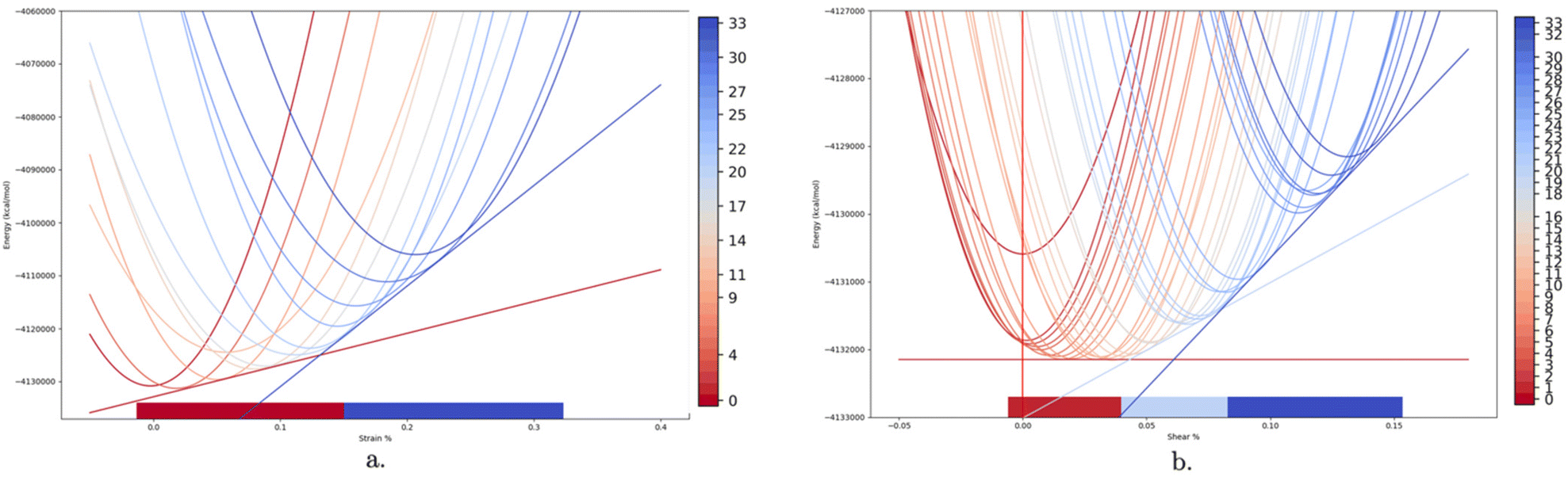 | ||
| Fig. 4 (a) Compression simulations of the M18 phase. (b) Shear simulations of the M18 phase. The parabolas of plastic yield extracted from the analysis are described in the text. | ||
It is important to emphasize the qualitative difference between the plastic response in shear (Fig. 4b) or compression (Fig. 4a) in the stress–strain diagram of the M18 phase. In compression, we find an initial narrow elastic region (up to 5% strain), followed by two plastic flow régimes between 5% and 33% strain (highlighted in orange and blue in Fig. 4, with isotangent plastic flow stresses of 135 MPa and 520 MPa, respectively), finally leading to a hard-wall strain-hardening region for strain >33%.
The stress–strain profile in shear is slightly more irregular, with a re-adjustment of the initial structure observed within a low shear strain of 2%. Most importantly, the analysis of the inherent structures and their associated parabolas provides a key difference between the two strain modes.
As shown in Fig. 4b, in shear we find for M18:
• an initial region, up to 4–5% strain (highlighted in red in Fig. 4b), in which the parabolas shift in their equilibrium shear-strain positions, while their minimum energy stays practically constant around a common value. These transitions, which (to the best of our knowledge) are reported here for the first time, correspond to plastic modes with a very small (almost negligible) yield stress, that we will hereafter refer to as “zero-stress” plastic modes.
This initial zero-stress region (which is absent in compression) is followed by two plastic flow regions at finite values of yield stress (as observed also in compression):
• the first region (between 5% and 8% strain highlighted in light blue in Fig. 4a) has isotangent plastic flow stresses of 45 MPa and
• the second region between 8% and 16% strain, highlighted in dark blue in Fig. 4a, has isotangent plastic flow stresses of 88 MPa and,
• finally, a hard-wall strain-hardening region for strain >16%.
Note that all the isotangent plastic yield stresses in shear (≈0 in the “zero-stress” regions and 45–88 MPa in the following finite stress régime) are significantly smaller than those in compression (135–520 MPa).
This zero-stress plastic flow régime exhibiting negligible values of the yield stress shear is not specific to the M18 phase. Fig. S3 of the ESI† presents the isotangent construction for shear simulations on the M26 phase, showing the same qualitative behavior found for the M18 phase in Fig. 4b: for M26 the zero-stress region applies up to ≈4% strain, which is followed by a plastic flow region with isotangent stress of 56 MPa. Fig. S4b of the ESI† reports the isotangent construction for shear simulations on the M26 phase in the opposite direction (with a zero-stress region up to 4% and an isotangent at 34 MPa for larger strain). Fig. S4a of the ESI† reports the isotangent construction for shear simulations on the M34 phase. Here, we find an approximately similar behavior in that we find a first plastic régime with a low value of the yield stress (about 11 MPa), followed by an interval of strain with a higher yield stress value (93 MPa), then leading to a final strain hardening region. However, the more reticulated morphology of the M34 phase makes that the first plastic yield has a finite (non-negligible) isotangent value of 11 MPa up to 4% shear strain. This corresponds to a yield stress larger by orders of magnitude than in the “zero-stress” régime of the M18 and M26 phases, and therefore to a qualitatively different mechanical response. The M34 phase corresponds in our view6 to materials experimentally obtained at a higher temperature, leading to a more reticulated, 2D network of bonds, and thus larger graphene-like areas. The zero-stress region thus depends on the size of the graphene flakes.
To investigate the dependence of this unique “zero-stress” region upon the mass density of the carbonaceous material, we applied the same protocol for shear calculations to the M18 DynReaxMax phase prepared at 2000 K with a density of 0.50 g cm−3.6 The results are summarized in Fig. 5. As for the 0.16 g cm−3 phase, we observe a similar initial collapse of the structure yielding a phase at lower energy with an equilibrium strain at the minimum shifted by a few percent. Then, we find a first meaningful plastic régime. The isotangent construction in this initial plastic relaxation of the M18 phase at 0.50 g cm−3 differs significantly with respect to those of M18 and M26 at 0.16 g cm−3. Indeed, it shows:
• a non-negligible slope, giving rise to an initial non-zero yield stress of ≈4 MPa and
• a much narrower region of plasticity (of only about 1% strain range).
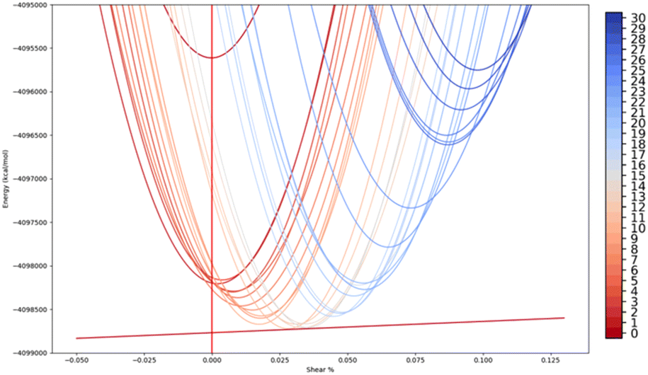 | ||
| Fig. 5 Shear simulations of the M18 phase at 0.5 g cm−3 density. The parabolas of plastic yield extracted from the analysis are described in the text. | ||
Moreover, the M18 0.50 g cm−3 structure stress/strain response exhibits more of an elastic-type behavior than any of the phases at 0.16 g cm−3 for two reasons:
• at least four isotangent constructions are needed to reach 10% deformation, each one enveloping a very small number of parabolas, suggesting that for the 0.50 g cm−3 phase the plastic flow is also due to the discrete sampling of deformations.
• The relaxation paths at step (iii) of the computational protocol (see the Computational approach section below) are longer and converges to lower deformations. For instance, by comparing Fig. 4b and 5, we notice that the minimum of the parabolas at 30% deformation converges to a shear strain of 11.9% and 9.8% respectively, implying that the denser phase is more elastic.
We therefore argue that our finding of a zero-stress region followed by two shear regions of increasing stress and modulus, and terminated by a very stiff region is general: (a) for lower density carbonaceous phases, (b) with a structure similar to M18 and M26, whose morphologies mimic the phases obtained at lower postprocessing temperature.
This makes it important to identify the atomistic mechanisms underlying these modes exhibiting very low yield stresses. To this aim, we calculated the atomic displacement vector fields obtained as the difference of the atomic coordinates between the inherent structure at the beginning of the plastic flow region and the inherent structure at the end of this region. To do this we mapped the Cartesian coordinates into a common reference unit cell via an affine transformation, as detailed in the Computational approach section.
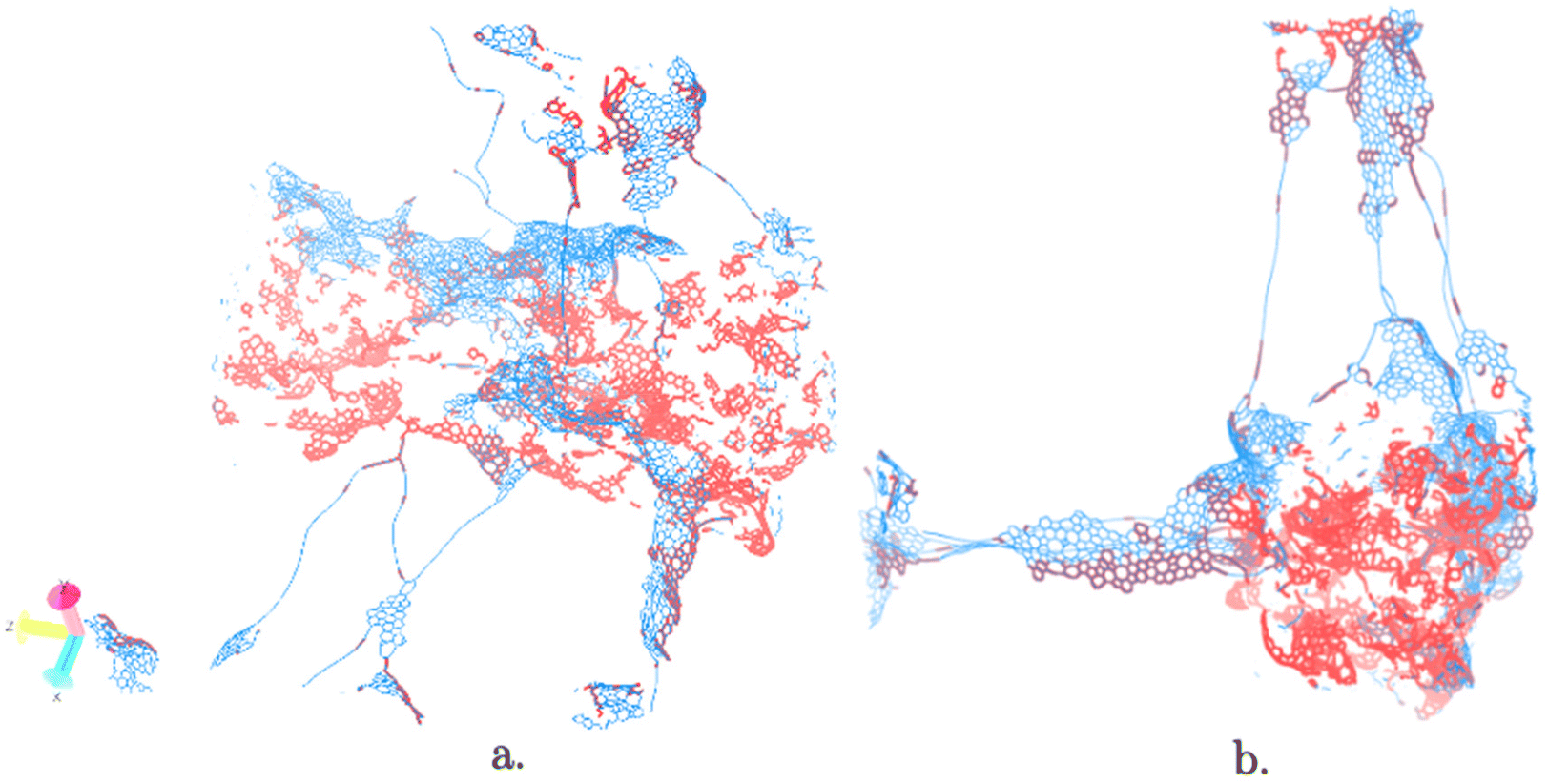
This displacement field can be visualized in various ways to emphasize the regions that undergo the largest displacements. Fig. 6 shows a plot of the scalar field induced by the modulus of the displacement vector field obtained by comparing the inherent structures at the beginning and at the end of the zero-stress flow in shear for the M18 phase (Fig. 4b). The field is visualized as a yellow-black-cyan color scale (yellow for the least displacing atoms, cyan for the most displacing atoms). First, we note that most atoms exhibit a displacement smaller than 0.5 Å (atoms displacing more than 0.5 Å, representing only 0.3% of the total, have been neglected in the plot to maintain clarity). Second, importantly, we can derive from Fig. 6 that the plastic shear mode at zero-stress has a collective character, involving atoms distributed all over the system. This collective character holds regardless of the local density, making it convenient to discuss separately the high-density regions (the fiber-like clumps) that resemble multi-wall carbon nanotubes from the low-density regions that consist mainly of single graphitic sheets or carbon chains. In the high-density clump, two shear bands (in cyan) are apparent, separated by a distance of ≈25 Å with non-mobile regions (yellow) in between. The lower density regions are instead characterized by compression and expansions in the carbon atom chains that are typically wavy, with alternating yellow and cyan parts. By visualizing the displacement field as a vector in a 3D plot, rather than the modulus, it is possible to understand by a closer inspection how the collective mode translates and is realized in terms of local modes. A few of these local modes are illustrated in Fig. 7. Fig. 7a illustrates the bending of the graphitic sheets, which is the dominant effect observed in the low-density regions. In fact, this motion reduces the apparent length of the sheet itself (thereby alleviating stress) in one direction by occupying more space in the orthogonal direction. The mostly empty regions are suited to easily accommodate this expansion. Fig. 7b and c represent instead modes that take place inside the clump. Fig. 7b shows the collective character of the motion of a stack of sheets inside the densest region. Fig. 7c shows what we call a U-closing motion of U-shaped graphitic sheets. We observe that U-sheets respond to stress by exhibiting a relative movement of one side of the U towards the other. We note here that U-closing can relieve stress without causing any expansion in other directions, which would be energy demanding in a higher density region. Combinations of these motions can take place at the same time causing sliding of sheets with respect to each other.
 | ||
| Fig. 6 Nanoscopic shear bands in the M18 phase subject to shear deformation visualized via the modulus of the displacement vector field. Color bar ranges from yellow to cyan upon increasing displacement. | ||
 | ||
| Fig. 7 Visualization of the displacement vector field for the zero-stress shear plastic transformations of the M18 phase for three cases. (a) Torsion movement inside a graphitic sheet for the M18 structure undergoing shear transformation; (b) translational motion of the denser region for the zero stress M18 shear transformation; (c) U-closing. Both walls move in the same direction, but the highlighted one moves more than twice as far as the other, causing a net distance decrease of −0.2 Å. | ||
Finally, it is important to emphasize that the atomic movements within the nanoscopic shear bands within the 1D-fibers associated with the zero-stress plastic mode do not correlate with local properties of the individual carbon atoms, as consistent with the collective character of the plastic mode. To demonstrate this, we performed MD simulations at 300 K for a period of 50 ps and extracted the atomic thermal ellipsoids (Debye–Waller factors) from the final 40 ps of the MD run. We then plotted the carbon atoms in the structure by coloring them according to the modulus of their Debye–Waller factor and of their displacement vector field, trying to match the atoms that displaced the largest displacements in the plastic mode (red) with those possessing the strongest thermal motions (blue). Fig. 8a illustrates the results of this comparison: we see clearly that matching is limited to the strings, which is a very limited portion of the clumps. Thus, we conclude that there is basically no correlation between plastic and thermal motions. The reason of this mismatch is simple: thermal motions are larger in the outside regions (external walls) of the clumps and are uniform in these regions, so that they do not exhibit a stripe (band) distribution, whereas the plastic flow in the inner regions of the fibers are localized in a nanoscopic shear band, as illustrated in Fig. 8b using a different view of the system.
 | ||
| Fig. 8 Simultaneous visualization of the modulus of the thermal ellipsoids and of the displacement vector field for the zero-stress plastic transformation in the M18 phase. Atoms that displaced the most in this plastic mode are colored in red, while those possessing the strongest thermal motions are colored in blue. (a) There is a reasonable match between thermally mobile and plastic atoms in the low-density region, whereas there is very little overlap in the clump region (in the center, along the z axis). (b) A different view of (a) with the axis of the clump orthogonal to the plane to better visualize the observation that the interior of the clump does not move in thermal motions (there is no blue component), whereas it undergoes plastic displacement in shear (red). | ||
Computational approach
Energy and forces were evaluated using the ReaxFF-C-2013 reactive force field, which we denote as C.ff.7,13 This force field was developed to achieve an accurate description of condensed carbon phases and trained against a variety of solid-state systems including diamond, graphene, and amorphous carbon. ReaxFF is in good agreement with quantum mechanics (PBE+D3 flavor of Density Functional Theory (DFT)) and with experimental data for the heat of formation of graphene (−175.0 kcal mol−1, −174.8 kcal mol−1 and −178.4 kcal mol−1, respectively) and bulk diamond (−174.27 kcal mol−1, −172.93 kcal mol−1 and −175.7 kcal mol−1, respectively). However, comparative studies show that the stability of carbon sp bonds is somewhat overestimated by the ReaxFF C.ff, which may affect the linear chain structures.14 Machine-learning force fields for carbon systems have been recently proposed,15 but our strategy here is to test the configurations derived in our previous study, whose atomistic and morphological details have been validated against TEM and spectroscopic experiments (see also Fig. S6 of the ESI†).6All simulations were carried out with the C code version of ReaxFF package available in the Large-scale Atomic/Molecular Massively Parallel Simulator (LAMMPS) code employing 3D-periodic boundary conditions.8 We performed either Molecular Dynamics (MD) simulations at 298 K or local energy minimizations. In the local minimizations we always optimized atomic Cartesian coordinates. The lattice parameters of the unit cell were sometimes frozen and sometimes fully optimized. In other cases, we constrained one cell axis for compression studies or a cell angle parameter for shear simulations. As the minimization of cell parameters and coordinates in the LAMMPS code is an ill-defined problem, we repeatedly cycled between fixed cell relaxations (which, in turn, are well-defined problems) and full/partial (cell and coordinates) relaxations until convergence. This allowed us to redefine the objective function at each iteration ensuring the minimizer does not get stuck in metastable configurations.9 Most often 40 cycles were sufficient for structures that did not undergo excessive deformation (<10%), while more compressed or sheared boxes required extra cycles (up to 60). Additionally, to further reduce the chance of the relaxation getting stuck in a shallow local minimum, we performed random perturbations of the atomic coordinates (|Δr| < 0.01 Å) prior to each minimization, except for the last five cycles whose coordinates were close to convergence. Engineering shear is defined as the ratio of the offset of the two parallel faces which undergo reciprocal displacement to the cell length between them, while compression is defined as one minus the ratio of the current cell side to its original value, as illustrated in Fig. 2.
Our starting atomistic configurations were taken from low-density DynReaxMas simulations at 2000 K at a density of 0.16 g cm−3, while a medium density configuration at 0.50 g cm−3 was included for comparison.6 The DynReaxMas computational approach generates atomistic structures of amorphous carbonaceous materials in excellent agreement with experimental data on porosity and with TEM imaging, as illustrated in Fig. S6 of the ESI† where we compare some simulated TEM images from DynReaxMas phases to two very different experimental phases from ref. 16,17. We underline that the simulated DynReaxMas TEM images were generated without any reference to experimental structures and the comparison was performed only a posteriori with high quality, high resolution TEM experimental images from recent literature. Our simulation cells contain 25![[thin space (1/6-em)]](https://www.rsc.org/images/entities/char_2009.gif) 056 carbon atoms with an initial size of 145 × 145 × 145 Å3. As discussed in ref. 6, choosing various ReaxFF parameters to be subjected to the massaging procedure in the DynReaxMas approach produces diverse phases, that correspond to different experimental synthesis conditions. In the current paper, we focus on three phases, generated by the M18, M26, and M34 DynReaxMas massages (see Fig. 1 of ref. 6 for the definition of the massaging parameters and the atomistic depiction of these initial phases). Before applying stress simulations to the structures, we first further minimized the coordinates and the cell parameters, leading to very small deviations from the published ones (<0.1% in a, b, c parameters, <0.05° in α, β, γ parameters).
056 carbon atoms with an initial size of 145 × 145 × 145 Å3. As discussed in ref. 6, choosing various ReaxFF parameters to be subjected to the massaging procedure in the DynReaxMas approach produces diverse phases, that correspond to different experimental synthesis conditions. In the current paper, we focus on three phases, generated by the M18, M26, and M34 DynReaxMas massages (see Fig. 1 of ref. 6 for the definition of the massaging parameters and the atomistic depiction of these initial phases). Before applying stress simulations to the structures, we first further minimized the coordinates and the cell parameters, leading to very small deviations from the published ones (<0.1% in a, b, c parameters, <0.05° in α, β, γ parameters).
We then investigated the mechanical response in the plastic régime of the selected DynReaxMas phases using the “inherent plastic structures” protocol proposed previously to simulate and analyze the plastic deformation of amorphous materials.10 In this approach, the plastic transition is interpreted within a Potential Energy Landscape (PES) theoretical framework as the crossing between ideal (or “inherent”) structures. This protocol consists of the following steps:
(i) we initially subject the DynReaxMas atomistic models to a sequence of fixed-cell shear or compressive deformations of increasing strain;
(ii) step (i) generates a set of deformed configurations that are then subjected to configurational and energy analyses, as follows:
(iii) we take the configurations resulting from fixed-cell deformations and fully relax them in both atomic Cartesian coordinates and lattice parameters of the unit cell;
(iv) step (iii) typically finds that structures resulting from increasing values of fixed-cell strain relax to correspondingly increasing values of equilibrium lattice parameters. These fully relaxed structures provide atomistic configurations representative of increasing values of strain;
(v) next, we calculate the elastic PES of each inherent structure by calculating the elastic modulus along the strain path and plot the corresponding parabolas as a function of the strain;
(vi) we take the isotangent envelope of the parabolas to graphically define the plastic yield stress in appropriate intervals of strain, as described below, depicted in Fig. S5 of the ESI† and applied in Fig. 4, Fig. 5, and Fig. S3, S4 of the ESI†;
(vii) finally, to single out, map, and visualize the atomistic mechanisms corresponding to plastic modes, we use a variant of the approach employed in ref. 10 to compare two inherent structures possessing different values of the unit-cell lattice parameters, based on visualizing the displacement field as described below.
For step (vi), the idea behind the isotangent envelope construction is that deformations with values of strain intermediate between sampled ones are realized by the system developing microstructures, i.e., fine mixtures of phases in equilibrium and satisfying compatibility conditions at interfaces.11 The plastic yield stress can then be obtained via an isotangent construction, as illustrated in Fig. S5 of the ESI† and discussed in detail in ref. 10.
In step (vii), to compare the atomic configurations of two inherent structures possessing different values of the unit-cell lattice parameters, we transform the Cartesian coordinates of one inherent structure into that appropriate to the lattice parameters of the other inherent structure through an affine transformation, and then we define, visualize, and analyze the vector field corresponding to the atomic displacement vectors between the atoms in the initial and final structure.
Note that at step (v), we did not implement in the present case a full “sweeping” protocol of performing fixed-cell energy minimizations moving back and forth along the strain path to define its stability range, and we limited ourselves to single geometry relaxations.10 Finally, Fig. S7 of the ESI† tests and shows the reproducibility of our measurements.
Conclusions
Stimulated by our experiments on very low-density aerogels, we investigated computationally the mechanical response of atomistic models of very low-density amorphous carbonaceous materials recently derived from our DynReaxMas approach.6 We focused on DynReaxMas graphitic phases with a mass density of 0.16 g cm−3, which correspond to the density estimated for the core regions of carbon aerogels (Fig. S1 and S6 in ESI†), and we considered three phases derived via different DynReaxMas massages (M18, M26, and M34) at a temperature of 2000 K. These phases exhibit two types of morphology, either:• made of denser regions (fiber-like clumps) alternating with string-like connectors (M18 and M26), or
• made of more reticulated frameworks (M34).
We subjected these 3 phases to compression and shear deformations and analyzed the resulting mechanical response in the plastic régime in terms of the “inherent plastic structures” protocol in which the plastic transition is interpreted within a Potential Energy Landscape (PES) theoretical framework as the crossing between ideal (or “inherent”) structures.10
The most important outcome of the present study is that low-density amorphous carbonaceous materials exhibit plastic relaxation modes in shear with an extremely low value of yield stress, negligible with respect to the finite values in shear outside this “zero-stress” region or in compression. Analysis of the atomistic relaxation mechanisms shows that these modes involve both the clumps and the strings with a collective and cooperative character that does not correlate with thermal motions. In the clumps, this collective mode assumes the form of nanoscale shear bands, which translate into local movements such as translations, twisting, or U-closing of graphitic sheets. Our simulations rationalize our and other experimental observations of extremely low-stress plastic deformation modes in carbon aerogels.3 This provides the basis for multi-scale modeling of these materials, to eventually derive a constitutive model describing their mechanical response and plasticity.12
Author contributions
G. C.: investigation; data curation; resources; software; visualization; writing – original draft/K. X. & X. W.: validation; writing – review & editing/W. A. G.: conceptualization; supervision; funding; writing – review & editing/A. F.: conceptualization; methodology; formal analysis; supervision; writing – review & editing.Conflicts of interest
There are no conflicts to declare.Acknowledgements
G. C. gratefully acknowledges the Center for High Performance Computing (CHPS) and Prof. Gigi Rolandi at Scuola Normale Superiore for providing CPU time within his B. Sc. thesis, as well as computational support within the ISCRA program of the Italian Cineca Supercomputing Center. This work has taken inspiration within International Research Network IRN on Nanoalloys (CNRS) and the COST Action CA21101 “Confined molecular systems: from a new generation of materials to the stars” (COSY) supported by COST (European Cooperation in Science and Technology). A. F. and W. A. G. received support from NSF (CBET-1805022, CBET-2005250, and CBET-2311117).Notes and references
- H. Hu, et al. , Adv. Mater., 2018, 25, 2219–2223 CrossRef PubMed.
- A. Thakur, Mater. Today: Proc., 2022, 65, 3369–3376 Search PubMed.
- A. Lele, Disruptive Technologies for the Militaries and Security, Springer, Singapore, 2018 Search PubMed.
- H. Zhuo, et al. , Adv. Mater., 2018, 30, 1706705 CrossRef PubMed.
- C. Lee, et al. , Science, 2008, 321, 385 CrossRef PubMed.
- S. Monti, et al. , ACS Nano, 2021, 15(4), 6369–6385 CrossRef PubMed.
- K. D. Nielson, et al. , J. Phys. Chem. A, 2005, 109, 493–499 CrossRef PubMed; A. C. T. Van Duin, et al. , J. Phys. Chem. A, 2001, 105, 9396–9409 CrossRef.
- S. Plimpton, J. Comput. Phys., 1995, 117, 1–19 CrossRef.
- LAMMPS manual, https://docs.lammps.org/fix_box_relax.html, accessed June 26, 2023.
- A. Fortunelli, et al. , J. Chem. Phys., 2004, 121(10), 4941–4950 CrossRef PubMed.
- S. Müller , presented in part at Centro Internazionale Estivo (C.I.M.E.), Cetraro, Italy, June 1996; S. Müller, in Calculus of Variations and Geometric Evolution Problems, ed. F. Bethuel, G. Huisken, S. Müller, K. Steffen, S. Hildebrandt and M. Struwe, Springer, Berlin, 1999 Search PubMed.
- A. Fortunelli and M. Ortiz, Phys. Rev. E: Stat., Nonlinear, Soft Matter Phys., 2007, 76, 041806 CrossRef PubMed.
- S. G. Srinivasan, et al. , J. Phys. Chem. A, 2015, 119(4), 571–580 CrossRef PubMed.
- C. de Tomas, et al. , Carbon, 2019, 155, 624–634 CrossRef.
- P. Rowe, et al. , J. Chem. Phys., 2020, 153(3), 159901 CrossRef PubMed.
- D. Liu, et al. , Small Methods, 2020, 4, 1900827 CrossRef.
- H. Zhang, et al. , Small Methods, 2020, 4, 2000016 CrossRef.
Footnote |
| † Electronic supplementary information (ESI) available. See DOI: https://doi.org/10.1039/d3nr04067d |
| This journal is © The Royal Society of Chemistry 2023 |