 Open Access Article
How an ACE2 mimicking epitope-MIP nanofilm recognizes template-related peptides and the receptor binding domain of SARS-CoV-2†‡
Xiaorong
Zhang
 a,
Armel T.
Waffo
 b,
Aysu
Yarman
ac,
Norbert
Kovács
 d,
Zsófia
Bognár
 de,
Ulla
Wollenberger
a,
Ibrahim M.
El-Sherbiny
 f,
Rabeay Y. A.
Hassan
f,
Frank F.
Bier
a,
Róbert E.
Gyurcsányi
f,
Rabeay Y. A.
Hassan
f,
Frank F.
Bier
a,
Róbert E.
Gyurcsányi
 *de,
Ingo
Zebger
 b and
Frieder W.
Scheller
*a
aInstitute of Biochemistry and Biology, University of Potsdam, Karl-Liebknecht Str. 24–25, 14476 Potsdam, Germany. E-mail: fschell@uni-potsdam.de
bInstitut für Chemie, PC 14 Technische Universität Berlin, Straße des 17. Juni 135, 10623 Berlin, Germany
cMolecular Biotechnology, Faculty of Science, Turkish-German University, Sahinkaya Cad, 86, Beykoz, Istanbul 34820, Turkey
dDepartment of Inorganic and Analytical Chemistry, Faculty of Chemical Technology and Biotechnology, Budapest University of Technology and Economics, Műegyetem rkp. 3, H-1111 Budapest, Hungary. E-mail: gyurcsanyi.robert@vbk.bme.hu
eELKH-BME Computation Driven Chemistry Research Group, Műegyetem rkp. 3, H-1111 Budapest, Hungary
fNanoscience Program, University of Science and Technology (UST) & Center for Materials Science (CMS), Zewail City of Science and Technology, Giza 12578, Egypt
First published on 15th November 2022
Abstract
Here we aim to gain a mechanistic understanding of the formation of epitope-imprinted polymer nanofilms using a non-terminal peptide sequence, i.e. the peptide GFNCYFP (G485 to P491) of the SARS-CoV-2 receptor binding domain (RBD). This epitope is chemisorbed on the gold surface through the central cysteine 488 followed by the electrosynthesis of a ∼5 nm thick polyscopoletin film around the surface confined templates. The interaction of peptides and the parent RBD and spike protein with the imprinted polyscopoletin nanofilm was followed by electrochemical redox marker gating, surface enhanced infrared absorption spectroscopy and conductive AFM. Because the use of non-terminal epitopes is especially intricate, here we characterize the binding pockets through their interaction with 5 peptides rationally derived from the template sequence, i.e. implementing central single amino acid mismatch as well as elongations and truncations at its C- and N- termini. Already a single amino acid mismatch, i.e. the central Cys488 substituted by a serine, results in ca. 15-fold lower affinity. Further truncation of the peptides to tetrapeptide (EGFN) and hexapeptide (YFPLQS) results also in a significantly lower affinity. We concluded that the affinity towards the different peptides is mainly determined by the four amino acid motif CYFP present in the sequence of the template peptide. A higher affinity than that for the peptides is found for the parent proteins RBD and spike protein, which seems to be due to out of cavity effects caused by their larger footprint on the nanofilm surface.
1. Introduction
COVID-19 diagnoses are based on three main approaches:1(i) detection of the viral genome by RT-PCR or isothermal amplification, most notably loop-mediated isothermal amplification (LAMP),2–4
(ii) detection of antibodies raised against COVID-19 as a result of the viral infection, and
(iii) detection of the antigenic segments of the virus, spike protein (S-protein) or the nucleocapside protein (N-protein).
In terms of antigenic segments, the spike glycoprotein (S-protein), which is a 150 kDa transmembrane protein located on the surface of the virus, is especially well suited for specific identification of SARS-CoV-2. Its 26 kDa receptor binding domain (RBD) is the docking area of the virus to the angiotensin converting enzyme 2 (ACE2) for entering the host cell by establishing a non-covalent interaction with an equilibrium dissociation constant in the lower nanomolar range.5 The sequence of RBD is unique to SARS-CoV-2, thus indicating that the RBD avoids cross reactivity with other human corona viruses. Since mutations may affect this recognition site, efforts have been made to implement affinity ligands that can be generated in a rapid manner for the relevant target proteins without the need for animal experiments and cell cultures. In this respect, molecularly imprinted polymers (MIPs) which are fully synthetic biomimetic recognition elements may substitute antibodies in binding assays and sensors.6–15 For the MIP-based detection of SARS-CoV-2 until now three different type of templates have been used for imprinting,16i.e., (i) the whole virus or virus-like particles17,18 (ii) the N-protein, S-protein or RBD19–24 and recently (iii) exposed peptide regions of the spike protein, i.e. epitope imprinting.25–27
We have shown earlier that the two-step approach involving oriented preimmobilization of the peptide on planar surfaces leads to higher density binding sites upon subsequent electropolymerization of the functional monomer as compared with the single-step “random” imprinting, which involves the electropolymerization of a premixed solution of the monomer and peptide.28 Indeed, the epitope imprinting approach proved effective at the selective recognition of SARS-CoV-2 and already the first such study proved high affinity and selective recognition of the RBD and the relevant virus like particle.25 The peptide chain of the RBD starting with L455 up to Y505 is the binding area of the RBD to ACE25 and we developed a MIP which used the nonapeptide 485–493 of the RBD as the epitope template. The peptide GFNCYFPLQ was first microspotted onto gold Surface Plasmon Resonance Imaging (SPRi) chips followed by the deposition of a polyscopoletin nanofilm and then the template removal by anodic potential pulses. The parent protein RBD was bound by these peptide imprinted nanofilms in the lower nanomolar concentration range with an affinity constant ranging from 2 to 18 nM, while human serum albumin (HSA) had no effect in 0.5% Tween20 solution.25 The utility of peptide sequences from the L445–Y505 region of the RBD was confirmed also by Mizaikoff's group which used the peptide 486–502 for the synthesis of MIP-covered magnetic nanoparticles (NPs) concluding that such MIPs can differentiate between different virus peptides.26 While the rebinding of the parent protein (or the whole virus) has utmost importance in terms of the analytical goal, the easy variation of the peptide sequences beyond proving the selectivity for the template sequence could be also used to gain further information on the binding sites formed by epitope imprinting. Therefore, while in our previous study we focused on the analytical performance of parent protein rebinding, here we attempted to “map” the binding properties of the formed imprints by a set of rationally designed peptides. As the template for the epitope imprinting we used the heptapeptide GFNCYFP (G485 to P491, G-Peptide) of the receptor binding domain with Cys488 at the central position. After the chemisorption of the peptide through the cysteine, a polyscopoletin nanofilm was electrosynthesised and the template was removed by oxidative anodic stripping (Scheme 1). A series of target peptides were designed to study the binding cavity as compiled in Table 1. This includes changing the central cysteine to serine (S-Peptide), and extending the C-terminal site up to Q493 along with extending the N-terminal site with E484 (E-Peptide) that is exchanged by lysine in the Beta and Gamma variants.29,30 Further truncation and extensions to the G-Peptide template were made on the N- and C-terminal flanks of the central Cys488, e.g. the tetrapeptide EGFN and the hexapeptide YFPLQS.
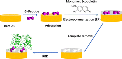 | ||
| Scheme 1 Workflow of MIP preparation and binding of RBD (PDB code: 6M0J). It was assumed that the template G-Peptide (GFNCYFP) was adsorbed “horizontally” via Cys488 on the bare gold. | ||
| Peptide | Abbreviation | Note |
|---|---|---|
| The length of the peptide chain was systematically varied at both termini of the central cysteine (Cys488, in the parent protein). Notably, the amino acids chosen for the elongation of the template G-Peptide are present in this exact order in the amino acid sequence of RBD (E484 to S494). | ||
| GFNCYFP | G-Peptide | G485 to P491 of SARS-CoV-2 RBD, the template |
| EGFNCYFPLQ | E-Peptide | E484 to Q493 of SARS-CoV-2 RBD |
| ___NSYFPLQ | S-Peptide | Cys488 was replaced by serine |
| ___CYFPLQS | C-Peptide | Cys488 to S494 of SARS-CoV-2 RBD |
| ___YFPLQS | Y-Peptide | C-terminal branch of the template |
| EGFN___ | FN-Peptide | N-terminal branch of the template |
2. Experimental section
2.1. Materials and methods
To prepare the MIP, the clean gold wire electrode was first incubated in 5 μM G-Peptide in PBS for 1.5 min at room temperature. The polyscopoletin layer was then deposited on the electrode by electropolymerizing a solution containing 0.5 mM scopoletin in 10 mM NaCl (5% (V/V) ethanol) with 20 pulse cycles starting with 0 V for 5 s followed by 0.7 V for 1 s. Non-imprinted polymers (NIPs) were prepared in the same way but without G-Peptide. After the synthesis of the polymer layer, the electrodes were carefully rinsed with water and then dried gently under a nitrogen stream.
To remove the immobilized G-Peptide from the polymer, anodic oxidation was performed in PBS by applying 900 mV for 30 s on the MIP electrode in two consecutive steps. After template removal, the MIP electrode was rinsed with water several times and gently dried with a nitrogen stream. For measuring the target binding the electrodes were then placed in 1 ml stirred ferri/ferrocyanide solution in PBS and 2 μl of the peptide or the parent protein solution at a specified concentration was injected. Both the template removal and rebinding were followed in time by SWV measurements performed every 5 min in the quiescent solution until the peak current stabilized.
![[double bond, length as m-dash]](https://www.rsc.org/images/entities/char_e001.gif) O) stretching vibration mode. The peptide was removed from the gold surface by applying a potential of 0.9 V (vs. Ag/AgCl in 3 M KCl) for 30 s. Subsequently, the corresponding spectral changes were traced in the IR-regime. NIP was prepared following the same workflow, thereby omitting the initial peptide immobilization. Binding of peptides and the RBD was verified by means of SEIRA spectroscopy via their characteristic amide I/II bands.
O) stretching vibration mode. The peptide was removed from the gold surface by applying a potential of 0.9 V (vs. Ag/AgCl in 3 M KCl) for 30 s. Subsequently, the corresponding spectral changes were traced in the IR-regime. NIP was prepared following the same workflow, thereby omitting the initial peptide immobilization. Binding of peptides and the RBD was verified by means of SEIRA spectroscopy via their characteristic amide I/II bands.
3. Results and discussion
3.1. Epitope-imprinted polymer electrosynthesis and template binding
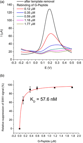
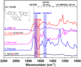
The epitope-imprinted polymer was synthesized using G-Peptide as the template and all steps were monitored by SWV in ferrocyanide solution. The peptide adsorption resulted in a significant decrease of the peak current of the bare gold electrode (650 μA) suggesting that around 70% of the gold surface is blocked to the access of the redox mediator, i.e., occupied by the template peptide. After electropolymerization of scopoletin the signal was completely suppressed indicating the deposition of an insulating polyscopoletin film. The template removal was performed by anodic stripping of the peptide at 900 mV as we found earlier that under these conditions the Cys-containing peptides are released from the electrode surface while the polymer integrity is unaltered.28 The successful removal is supported by the recovery of the SWV signal to ca. 130 μA indicative of the formation of template liberated free cavities in the polymer film through which the redox mediator regains access to the underlying gold electrode. The template G-Peptide binding at increasing concentrations could be clearly detected through the decrease in the peak current owing to the gradual filling of the imprinted cavities (Fig. 1A). The concentration dependence of the G-Peptide binding followed closely the Langmuir adsorption model from which a dissociation constant KD of 57.6 ± 0.01 nM was obtained (Fig. 1B).Further insight into the same succession of the synthesis and rebinding of the template was obtained by SEIRA spectroscopy. SEIRA measurements also confirmed the G-Peptide chemisorption onto the gold surface via the amide I and amide II bands centred at 1673 cm−1 and 1515 cm−1, respectively (Fig. 2, trace 1, black). The electrosynthesis of the polyscopoletin around the chemisorbed G-Peptide template on the gold surface was monitored through the characteristic polymer bands (trace 2, blue), namely the carbonyl ν(C![[double bond, length as m-dash]](https://www.rsc.org/images/entities/char_e001.gif) O) stretching vibration (1715 cm−1), aromatic and vinyl ν(C
O) stretching vibration (1715 cm−1), aromatic and vinyl ν(C![[double bond, length as m-dash]](https://www.rsc.org/images/entities/char_e001.gif) C) stretching modes (1600–1400 cm−1), ν(C–O) stretching vibration of the ester group (1280 cm−1), and the ν(C–O–C) stretching of alkyl ethers (1160 cm−1).28,34 The anodic pulse induced electrochemical removal of the G-Peptide from the polymer matrix was confirmed through the broad absorption band at ca. 1640 cm−1 that appears following the removal (trace 4, red). This is attributed to the δ(O–H) bending vibrations (red rectangle) of water molecules reaching the gold surface via the created MIP cavities. Subsequent rebinding of target molecules including G-Peptide (trace 4, red) and RBD (Fig. 7A, trace 2) leads to the (re)appearance of amide I and II bands, which can be better visualized from the corresponding difference spectrum (diff 4–3, violet) between trace 4 and trace 3.
C) stretching modes (1600–1400 cm−1), ν(C–O) stretching vibration of the ester group (1280 cm−1), and the ν(C–O–C) stretching of alkyl ethers (1160 cm−1).28,34 The anodic pulse induced electrochemical removal of the G-Peptide from the polymer matrix was confirmed through the broad absorption band at ca. 1640 cm−1 that appears following the removal (trace 4, red). This is attributed to the δ(O–H) bending vibrations (red rectangle) of water molecules reaching the gold surface via the created MIP cavities. Subsequent rebinding of target molecules including G-Peptide (trace 4, red) and RBD (Fig. 7A, trace 2) leads to the (re)appearance of amide I and II bands, which can be better visualized from the corresponding difference spectrum (diff 4–3, violet) between trace 4 and trace 3.
3.2. Revealing the presence of epitope-imprinted binding sites
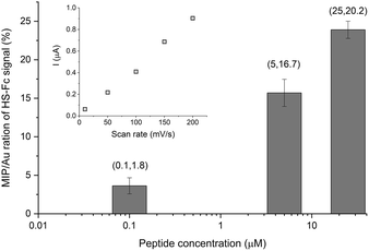
We further developed two original methods to confirm the full liberation of the binding cavities by the electrochemical template removal, i.e. the gold surface at the bottom of the binding cavities is exposed, as well as the surface concentration of the liberated sites scales with the surface concentration of the immobilized epitopes. To estimate the density of the binding cavities gold electrodes were modified with different G-Peptide concentrations and after the template removal we used a surface confined redox molecule, 6-(ferrocenyl)hexanethiol (HS-Fc). Thus, after template removal the MIP nanofilm was incubated in a 1 mM ethanolic solution of HS-Fc for 1 h and after thoroughly washing the excess of reagent the signal of the surface confined ferrocene derivative was measured by CV (see the ESI‡ for details of the procedure). The linear dependence of the peak current on the scan rate confirms the surface confinement (Fig. 3 inset). Fig. 3 shows the NIP corrected ratios of the HS-Fc anodic peak for the MIP after the template removal and for the free gold indicative of the ratio of the respective surface areas. There is a clear dependence on the peptide concentration used for immobilization and the gold surface exposed through the free binding sites, which at the experimental conditions used further in this paper (5 μM peptide) makes up ca. 17% of the nanofilm covered area.We set to provide a more explicit confirmation of the physical presence of the binding cavities by AFM. The contact AFM measurements coupled with nanolithography to remove locally the polymer layer showed that the electrosynthesised polyscopoletin film is ca. 5 nm thick (Fig. S1‡) and is fully insulating as revealed by c-AFM measurements (Fig. S2‡). Such ultrathin films are necessary for surface imprinting to ensure an efficient exchange of the template with the solution, i.e. to avoid entrapment of the immobilized templates in the polymer film. After the template removal the physical model suggests that nanocavities in contact with the underlying gold surface are formed, but it is extremely difficult to detect the presence of such molecular dimension cavities in a polymer nanofilm by topographic AFM and by c-AFM measurements (Fig. S3‡). This is due to the inherent roughness of the gold and the polymer layer to which adds that the conductive tips are not sufficiently sharp and that for appropriate electrical contact higher forces need to be applied that may damage the polymer film. Therefore, we explored for the first time the use of gold plating to reveal the presence of the binding cavities. Our hypothesis was that gold is electrodeposited in the open binding cavities and by growing out of the cavity generates gold particles on the surface, which can be readily assessed by AFM. Fig. 4 shows side-by-side the topography and the current map of the exact same location on a NIP and a MIP surface. On the NIP surface there are a few pinholes/defects that could be revealed by the gold plating. When correlating the topographic image of the NIP with the current map it is interesting to note that there are more protuberances visible in the topographic mode that are, however, absent from the current map. This confirms the discriminative power of the c-AFM measurements, i.e. only the gold particles connected to the underlying electrode surface are detected.
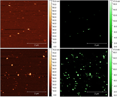 | ||
| Fig. 4 AFM (A and C) and conductive AFM (B and D) images of the NIP (A and B) and MIP (C and D) films after a 30 s electrodeposition of gold from a 0.2 mM HAuCl4 solution. | ||
In the case of the MIPs there is a clear correlation between the detected local elevation in the topographic mode and the conducting spots in the current map. However, the current map, in contrast to the NIPs, is more sensitive and identifies a higher number of binding pockets than the topographic image. The size of the detected gold nanoparticles (> ca. 10 nm) as shown also by high resolution current maps (Fig. S2‡) is larger than that expected for a molecular dimension cavity, which is most likely due to the rapid growth of the gold in a mushroom type manner, i.e. extending laterally. While at this stage we made no effort for a full optimization of the methodology, the results qualitatively enforce the “physical identity” of the epitope generated binding pockets.
3.3. “Mapping” the binding pocket through their peptide sequence recognition
The selectivity of the G-Peptide-imprinted polyscopoletin nanofilms was investigated through binding studies of different peptides with amino acid motifs derived from the G-Peptide template (Table 1). The purpose was to identify the length and the sequence motifs that are recognized by the MIP and their contribution to the affinity of the interaction. The highest affinity was found for the template epitope G-Peptide (KD = 58 nM) and the Cys-containing C-Peptide which is strongly truncated at the N-terminus with 3 amino acids and elongated at the C-terminus with another 3 amino acids (Fig. 5). The high toleration towards elongation suggests that the tetrapeptide sequence CYFP is at the core of the high affinity recognition. This is confirmed by replacing in the G-Peptide the central cysteine (Cys488 in the native protein) with a serine, which results in a ca. 15-fold decrease in the affinity, i.e. a 15-fold higher KD value of 859.6 ± 0.1 nM. Interestingly, if keeping the CYFP motif but elongating the peptide with a single amino acid at the N-terminus (E-Peptide) decreases the affinity even more than the central amino acid mismatch.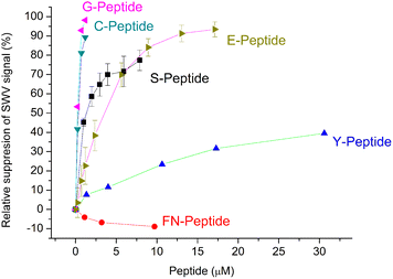 | ||
| Fig. 5 Comparison of the binding of the template peptide (G-Peptide) and related peptides to the MIP. Error bars for n = 3. | ||
Further confirmation of the importance of CYFP is provided by the again dramatically decreased binding shown by the hexapeptide Y missing just the cysteine from the core sequence (Fig. 5) which is supported by SEIRAS measurements (Fig. S4‡). Finally, the tetrapeptide FN that has no overlapping with the core sequence and is additionally elongated at the N-terminus shows no binding at all to the G-Peptide imprinted polymer.
The results are consistent with a previous finding of Piletsky's group that at least four common amino acids with the target are required for effective binding of the peptides to the MIP,35i.e. the peptides that share only 3 amino acids with the core motif of the template Cys-free Y- and FN-Peptides show the lowest binding to the MIP.
The linear measuring range obtained for the RBD-derived peptides is comparable with the values for the MIPs described for the epitopes of cardiac troponin T (TnT) and human serum albumin (HSA),36,37 but almost one order of magnitude lower than that for MIPs for cytochrome c-derived peptides38,39 and oxytocin.40 Only some studies, which claim measuring ranges in the pM concentration range, e.g., for pro-gastrin releasing peptide and insulin,41,42 shows values superior to the KD values reported here.
3.4. Protein recognition
Certainly the epitope-imprinted polymers are prepared with the intention to selectively bind the parent proteins, which in this case are the RBD and spike protein of SARS-CoV-2. The redox marker gating measurements using SW voltammetry revealed binding to the MIP in the lower nM-range reaching saturation around 50% suppression of the peak current after template removal (Fig. 6). At the same time the MIP exhibits a very low affinity towards HSA.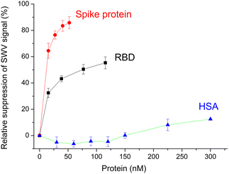 | ||
| Fig. 6 Concentration dependences of the binding of RBD, spike protein and HSA to the MIP. Error bars for n = 3. | ||
Indeed, when testing the binding of RBD and spike protein to the MIP in the 1![[thin space (1/6-em)]](https://www.rsc.org/images/entities/char_2009.gif) :
:![[thin space (1/6-em)]](https://www.rsc.org/images/entities/char_2009.gif) 20 diluted Hotgen buffer (the sample extraction buffer for the SARS-CoV-2 antigen test with a high HSA background) we observed a tolerable suppression of the binding signal of up to 20% in comparison with the signal measured in the absence of Hotgen buffer (Fig. S5‡).
20 diluted Hotgen buffer (the sample extraction buffer for the SARS-CoV-2 antigen test with a high HSA background) we observed a tolerable suppression of the binding signal of up to 20% in comparison with the signal measured in the absence of Hotgen buffer (Fig. S5‡).
Compared to the G-Peptide, the affinity of the MIP toward the RBD was almost four-fold higher as reflected by the KD of 14.7 ± 0.9 nM and even higher towards the spike protein (KD = 10.8 ± 0.6 nM). The lower nM KD values are comparable with the values that were recently determined by SPRi for RBD binding in a similar system, but with the epitope-imprinted nanofilms prepared on a planar chip by a combination of peptide microspotting and electrosynthesis, i.e. 2.2 ± 0.4 nM.25
Since theoretically there is 1![[thin space (1/6-em)]](https://www.rsc.org/images/entities/char_2009.gif) :
:![[thin space (1/6-em)]](https://www.rsc.org/images/entities/char_2009.gif) 1 binding between the MIP and all type of targets (peptide and parent proteins) the KD values should not change. The fact that they change suggests additional contributions in the case of the larger molecular weight proteins. Their footprint upon binding to the MIP is larger on the surface than that of the peptide and may contribute to blocking adjacent binding sites from the access of the redox marker without a specific interaction. Fig. 6 shows clearly that the relative suppression of the SWV signal by the 138 kDa spike protein is over 80% while for ∼26 kDa RBD levels it is at only ca. 50% confirming the contribution of the molecular size of the target.
1 binding between the MIP and all type of targets (peptide and parent proteins) the KD values should not change. The fact that they change suggests additional contributions in the case of the larger molecular weight proteins. Their footprint upon binding to the MIP is larger on the surface than that of the peptide and may contribute to blocking adjacent binding sites from the access of the redox marker without a specific interaction. Fig. 6 shows clearly that the relative suppression of the SWV signal by the 138 kDa spike protein is over 80% while for ∼26 kDa RBD levels it is at only ca. 50% confirming the contribution of the molecular size of the target.
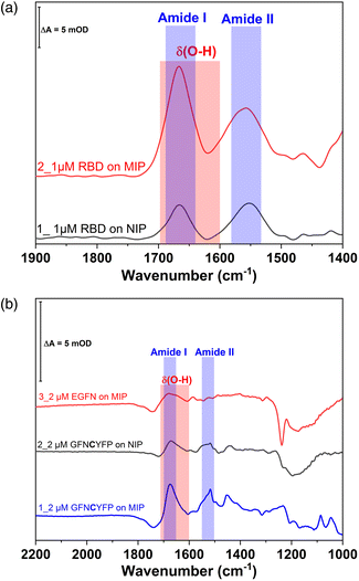
The redox marker gating based readout of the target binding to the MIP assumes that the permeability of the redox marker through the polymer nanofilm reflects the degree of occupancy of the binding cavities by the target analyte. However, non-specific binding of the analyte or of any other component of the sample to the outer surface of the polymer scaffold can also decrease the current signal. Binding of the proteins to the non-imprinted polymer cannot be quantified by this technique because NIPs lack imprinted cavities.28 Therefore, non-specific binding of G-Peptide to the NIP was also investigated by SEIRA spectroscopy (Fig. S6‡). The difference spectrum depicted as trace 3 with amide I and II bands centered at 1673 and 1517 cm−1 indicates a weak non-specific binding of the G-Peptide to the polyscopoletin film. This non-specific binding could not be suppressed in 3 M NaCl. Compared with the MIP (Fig. 2), the band intensity, which reflects the binding of G-Peptide to NIP was around 4-fold lower (Fig. 7B). The degree of non-specific binding of RBD was comparable with that of the G-Peptide. As represented in Fig. 7A, the intensity of the amide I band for the adsorbed RBD was almost 3.5-fold higher at the MIP than for the NIP.
4. Conclusions
In our view, using a peptide epitope for imprinting has essential advantages in terms of cost effectiveness and selectivity.39 Peptides, especially short peptides, can be generated by chemical synthesis in large quantities and with high purities in a reproducible manner with emerging bioinformatic approaches for their selection.43 In contrast, pure virus formulations suitable as templates for imprinting are very hard to obtain, and the use of the protein antigens comes at higher costs. Finally, it is inherently advantageous to use a unique peptide sequence instead of the parent protein that may show a high degree of homology with other virus proteins and accordingly lead to cross-reactivity of the respective MIPs. In this paper we addressed several open questions concerning the formation and target binding mechanism of epitope-imprinted polymers which are still controversially discussed in the literature. This includes proposing new methods for the qualitative visualization, at this stage, of the imprinted binding cavities and evaluation of their density as well as investigating and mapping the binding sites with various sequence peptide targets. Our results show that it is possible to identify the main contributor in terms of the imprinted sequence to the affinity of the epitope-imprinted polymer. We consider that these add significantly to the understanding of the epitope-imprinted nanofilms.Minuni's group37 reported that a MIP which used an “upright” oriented linear peptide as the template cannot bind inner (“horizontal”) epitopes of the parent protein. Here we tackled this problem utilizing a peptide from the binding area of the RBD to the ACE2 receptor as the template, with a cysteine in the center for the electrosynthesis of the MIP. Chemisorption of the peptide via the cysteine to the gold electrode surface resulted in cavities allowing effective recognition of the RBD and the spike protein.
Intuitively, it is expected that epitope-imprinted MIPs have lower affinity (larger KD) for the parent proteins, that bind 1![[thin space (1/6-em)]](https://www.rsc.org/images/entities/char_2009.gif) :
:![[thin space (1/6-em)]](https://www.rsc.org/images/entities/char_2009.gif) 1 to the MIP through a single cavity, as the peptide epitope. In fact, in our earlier study on a cytochrome c-MIP with fluorescence readout we found that the target peptide shows a stronger binding than the parent protein.38
1 to the MIP through a single cavity, as the peptide epitope. In fact, in our earlier study on a cytochrome c-MIP with fluorescence readout we found that the target peptide shows a stronger binding than the parent protein.38
This might be explained by the fact that during “indirect” detection methods, like the redox marker gating, the binding of the parent protein results in the “blockage” of several epitope cavities due to the larger footprint of the protein on the surface. Because the cross section of a globular protein will increase with the square root of the molecular weight, the observed apparently higher affinity of the total spike protein as compared to the smaller RBD can be explained by this “shielding” effect. However, non-specific interactions as shown by SEIRA at the polymer surface can also result in apparently larger affinity. Measurements with the MIP sensors in real biological samples, e.g., blood, or in our case in “splitting buffer” are still complicated by the presence of highly abundant proteins in the g L−1 region, e.g., albumin, while biomarkers are typically in the mg L−1 to ng L−1 range.34 Since MIP sensors represent only one “separation plate”, it is challenging to reach the required selectivity. Typically, a cross-reactivity of 10% has been reported based on the measurement of the separate binding of the analyte and the interferent.44 However, for measurements in real samples the simultaneous interaction of both species with the MIP is relevant. Accordingly, we demonstrated the binding of the RBD in the presence of a high excess of HSA and in the diluted splitting buffer.
Author contributions
X. Z., A. T. W., N. K., and Z. B.: investigation, formal analysis and visualization, and writing—original draft preparation; U. W., I. M. E., R. Y. A. H., R. E. G. and F. F. B.: funding acquisition and writing—review and editing; A. Y., R. E. G., I. Z., and F. W. S.: conceptualization, supervision, and writing—review and editing; and F. W. S.: project administration.Conflicts of interest
There are no conflicts to declare.Acknowledgements
The research reported in this paper is part of project no. BME -EGA-02 and BME-NVA-02, implemented with the support provided by the Ministry of Innovation and Technology of Hungary from the National Research, Development and Innovation Fund, financed under the TKP2021 funding scheme F. W. S. and A. Y. received support from DFG (EXC 2008–390540038–UniSysCat) and F. F. B. and X. Z. from the German Ministry of Education and Research (BMBF, 01DH20018).References
- M. Yüce, E. Filiztekin and K. G. Özkaya, Biosens. Bioelectron., 2021, 172, 112752 CrossRef PubMed.
- A. Ganguli, A. Mostafa, J. Berger, M. Y. Aydin, F. Sun, S. A. Stewart de Ramirez, E. Valera, B. T. Cunningham, W. P. King and R. Bashir, Proc. Natl. Acad. Sci. U. S. A., 2020, 117, 22727–22735 CrossRef CAS PubMed.
- S. Agarwal, C. Warmt, J. Henkel, L. Schrick, A. Nitsche and F. F. Bier, Anal. Bioanal. Chem., 2022, 414, 3177–3186 CrossRef CAS PubMed.
- V. L. Dao Thi, K. Herbst, K. Boerner, M. Meurer, L. P. M. Kremer, D. Kirrmaier, A. Freistaedter, D. Papagiannidis, C. Galmozzi, M. L. Stanifer, S. Boulant, S. Klein, P. Chlanda, D. Khalid, I. B. Miranda, P. Schnitzler, H. G. Kräusslich, M. Knop and S. Anders, Sci. Transl. Med., 2020, 12, 7075 CrossRef PubMed.
- Z. Liu, X. Xiao, X. Wei, J. Li, J. Yang, H. Tan, J. Zhu, Q. Zhang, J. Wu and L. Liu, J. Med. Virol., 2020, 92, 595–601 CrossRef CAS PubMed.
- G. Wulff and A. Sarhan, Angew. Chem., 1972, 84, 364–364 CrossRef.
- R. Arshady and K. Mosbach, Makromol. Chem., 1981, 182, 687–692 CrossRef CAS.
- S. Ramanavičius, I. Morkvėnaitė-vilkončienė, U. Samukaitė-bubnienė, V. Ratautaitė, I. Plikusienė, R. Viter and A. Ramanavičius, Sensors, 2022, 22, 1282 CrossRef PubMed.
- O. Hayden, P. A. Lieberzeit, D. Blaas and F. L. Dickert, Adv. Funct. Mater., 2006, 16, 1269–1278 CrossRef CAS.
- M. Menger, A. Yarman, J. Erdőssy, H. Yildiz, R. Gyurcsányi and F. Scheller, Biosensors, 2016, 6, 35 CrossRef PubMed.
- A. Yarman, S. Kurbanoglu, I. Zebger and F. W. Scheller, Sens. Actuators, B, 2021, 330, 129369 CrossRef CAS.
- S. Ramanavicius, A. Jagminas and A. Ramanavicius, Polymers, 2021, 13, 974 CrossRef CAS PubMed.
- R. Schirhagl, D. Podlipna, P. A. Lieberzeit and F. L. Dickert, Chem. Commun., 2010, 46, 3128–3130 RSC.
- E. Moczko, A. Guerreiro, C. Cáceres, E. Piletska, B. Sellergren and S. A. Piletsky, J. Chromatogr. B: Anal. Technol. Biomed. Life Sci., 2019, 1124, 1–6 CrossRef CAS PubMed.
- O. I. Parisi, F. Francomano, M. Dattilo, F. Patitucci, S. Prete, F. Amone and F. Puoci, J. Funct. Biomater., 2022, 13, 12 CrossRef CAS PubMed.
- A. Yarman and S. Kurbanoglu, Biomimetics, 2022, 7, 58 CrossRef CAS PubMed.
- H. A. Hussein, A. Kandeil, M. Gomaa, R. Mohamed El Nashar, I. M. El-Sherbiny and R. Y. A. Hassan, ACS Sens., 2021, 6, 4098–4107 CrossRef CAS PubMed.
- N. Cennamo, G. D'Agostino, L. Pasquardini, F. Arcadio, C. Perri, N. Coppola, I. F. Angelillo, L. Altucci, F. Di Marzo, E. M. Parisio, G. Camarlinghi and L. Zeni, Results Opt., 2021, 5, 100177 CrossRef.
- A. Raziq, A. Kidakova, R. Boroznjak, J. Reut, A. Öpik and V. Syritski, Biosens. Bioelectron., 2021, 178, 113029 CrossRef CAS PubMed.
- V. Ratautaite, R. Boguzaite, E. Brazys, A. Ramanaviciene, E. Ciplys, M. Juozapaitis, R. Slibinskas, M. Bechelany and A. Ramanavicius, Electrochim. Acta, 2022, 403, 139581 CrossRef CAS PubMed.
- O. I. Parisi, M. Dattilo, F. Patitucci, R. Malivindi, V. Pezzi, I. Perrotta, M. Ruffo, F. Amone and F. Puoci, bioRxiv, 2020, 120709.
- T. Zhang, L. Sun and Y. Zhang, Anal. Methods, 2021, 13, 5772–5776 RSC.
- M. Amouzadeh Tabrizi, J. P. Fernández-Blázquez, D. M. Medina and P. Acedo, Biosens. Bioelectron., 2022, 196, 113729 CrossRef CAS PubMed.
- A. G. Ayankojo, R. Boroznjak, J. Reut, A. Öpik and V. Syritski, Sens. Actuators, B, 2022, 353, 131160 CrossRef CAS PubMed.
- Z. Bognár, E. Supala, A. Yarman, X. Zhang, F. F. Bier, F. W. Scheller and R. E. Gyurcsányi, Chem. Sci., 2022, 13, 1263–1269 RSC.
- B. Fresco-Cala, S. Rajpal, T. Rudolf, B. Keitel, R. Groß, J. Münch, A. D. Batista and B. Mizaikoff, Nanomaterials, 2021, 11, 2985 CrossRef CAS PubMed.
- J. McClements, L. Bar, P. Singla, F. Canfarotta, A. Thomson, J. Czulak, R. E. Johnson, R. D. Crapnell, C. E. Banks, B. Payne, S. Seyedin, P. Losada-Pérez and M. Peeters, ACS Sens., 2022, 7, 1122–1131 CrossRef PubMed.
- G. Caserta, X. Zhang, A. Yarman, E. Supala, U. Wollenberger, R. E. Gyurcsányi, I. Zebger and F. W. Scheller, Electrochim. Acta, 2021, 381, 138236 CrossRef CAS.
- M. H. Cheng, J. M. Krieger, A. Banerjee, Y. Xiang, B. Kaynak, Y. Shi, M. Arditi and I. Bahar, iScience, 2022, 25, 103939 CrossRef CAS PubMed.
- S. S. Negi, C. H. Schein and W. Braun, Sci. Rep., 2022, 12, 1128 CrossRef CAS PubMed.
- M. Osawa, in Near-Field Optics and Surface Plasmon Polaritons, Springer Berlin Heidelberg, Berlin, Heidelberg, 2001, pp. 163–187 Search PubMed.
- H. Miyake, S. Ye and M. Osawa, Electrochem. Commun., 2002, 4, 973–977 CrossRef CAS.
- R. Wen, A. H. Zhang, D. Liu, J. Feng, J. Yang, D. Xia, J. Wang, C. Li, T. Zhang, N. Hu, T. Hang, G. He and X. Xie, ACS Appl. Mater. Interfaces, 2019, 11, 43936–43948 CrossRef CAS PubMed.
- X. Zhang, G. Caserta, A. Yarman, E. Supala, A. F. T. Waffo, U. Wollenberger, R. E. Gyurcsányi, I. Zebger and F. W. Scheller, Chemosensors, 2021, 9, 128 CrossRef CAS.
- J. Settipani, K. Karim, A. Chauvin, S. M. Ibnou-Ali, F. Paille-Barrere, E. Mirkes, A. Gorban, L. Larcombe, M. J. Whitcombe, T. Cowen and S. A. Piletsky, J. Chin. Adv. Mater. Soc., 2018, 6, 301–310 CrossRef CAS.
- X. T. Ma, X. W. He, W. Y. Li and Y. K. Zhang, Sens. Actuators, B, 2017, 246, 879–886 CrossRef CAS.
- P. Palladino, M. Minunni and S. Scarano, Biosens. Bioelectron., 2018, 106, 93–98 CrossRef CAS PubMed.
- D. Dechtrirat, K. J. Jetzschmann, W. F. M. Stöcklein, F. W. Scheller and N. Gajovic-Eichelmann, Adv. Funct. Mater., 2012, 22, 5231–5237 CrossRef CAS.
- H. Nishino, C.-S. Huang and K. J. Shea, Angew. Chem., Int. Ed., 2006, 45, 2392–2396 CrossRef CAS PubMed.
- P. S. Sharma, Z. Iskierko, K. Noworyta, M. Cieplak, P. Borowicz, W. Lisowski, F. D'Souza and W. Kutner, Biosens. Bioelectron., 2018, 100, 251–258 CrossRef CAS PubMed.
- C. Rossetti, A. Abdel Qader, T. G. Halvorsen, B. Sellergren and L. Reubsaet, Anal. Chem., 2014, 86, 12291–12298 CrossRef CAS PubMed.
- C. Zhao, X. Ma and J. Li, Chin. J. Anal. Chem., 2017, 45, 1360–1366 CAS.
- A. M. Bossi and L. Pasquardini, Methods Mol. Biol., 2021, 2359, 269–283 CrossRef PubMed.
- J. Pang, P. Li, H. He, S. Xu and Z. Liu, Chem. Sci., 2022, 13, 4589–4597 RSC.
Footnotes |
| † This article is devoted to Klaus Mosbach on the occasion of his 90th birthday. |
| ‡ Electronic supplementary information (ESI) available. See DOI: https://doi.org/10.1039/d2nr03898f |
| This journal is © The Royal Society of Chemistry 2022 |

