In search of structure–function relationships in transition-metal based rectifiers†
Received
19th March 2014
, Accepted 30th April 2014
First published on 5th May 2014
Abstract
Heterometallic chains have been proposed as potential current rectifiers in molecular electronics, their left–right asymmetry providing, at least in principle, a mechanism for differentiation of current flow in forward and reverse directions. Here we compare two known extended metal atom chains (EMACs), Ru2Ni(dpa)4(NCS)2 and Ru2Cu(dpa)4(NCS)2, both of which meet the first criterion for rectification in so much as they are physically asymmetric. In both cases the dominant transport channel is a doubly degenerate π* orbital localised, to a first approximation, on the Ru2 unit. As a result, current is limited by tunnelling across the Au–SCN–Ni/Cu junction. The paramagnetic Ni centre tunes the left–right delocalisation of the channel, making the minority-spin (β) channel more transparent than its spin-α counterpart and this difference provides the basis for asymmetry in the current under forward and reverse bias.
Introduction
The discipline of molecular electronics is motivated by the desire to replace the semiconductor-based components of contemporary devices with molecular-based analogues.1 As a result, there is a great deal of interest in designing molecules which, when supported between two electrodes, may reproduce the functionality of wires, diodes and even transistors. As with all types of mimicry, even when the gross function (viz. electronic conduction or rectification) is replicated, it is not always clear that the underlying mechanism is the same. This point is illustrated by the recent surge in literature reports of ‘molecular rectifiers’, components which will allow the preferential flow of current in one direction.2–14 The p–n junction diode which lies at the heart of conventional semiconductor devices is the inspiration behind these studies, but to what extent do the physics and chemistry in these putative mimics really reflect the key features of the original? It is clear that the presence of any element of asymmetry, either in a molecule or its contact to an electrode, eliminates the possibility that current flow is rigorously identical in both directions. The question then becomes one of degrees: to what extent does the asymmetric perturbation impact on the observable of interest, the flow of current.
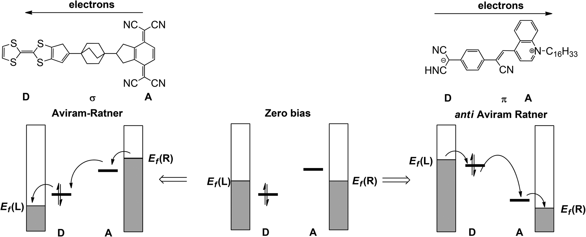
In the seminal 1974 paper15 where they identified the potential rectifying properties of the Donor–bridge-Acceptor (D–σ-A or D–π-A) architecture (Fig. 1, left), Aviram and Ratner argued that under applied bias electrons should flow preferentially from the source electrode to the vacant LUMO on the acceptor to the (filled) HOMO of the donor and finally to the drain electrode (the ‘Aviram–Ratner direction’). If the acceptor and donor are identified with the p- and n-doped regions of the semiconductor, then this implies the opposite direction for facile electron transport to that observed in a p–n junction (i.e. from electron-poor to electron-rich regions). Indeed a later study of the Aviram–Ratner diode using density functional theory suggested that the potential drop was localised at the electrode–molecule interface, and the computed rectification ratio was low.2 The Aviram–Ratner architecture shown in Fig. 1 (left) has not been realised synthetically but a number of closely related D–σ-A and D–π-A triads (Fig. 1, right, for example)4,5 have show rectification ratios of up to 60, albeit with preferential electron flow from the donor to the acceptor: i.e. in the ‘anti Aviram–Ratner’ direction.4a This direction of electron flow can be understood in terms of the strength of coupling of the donor and acceptor groups to the electrodes: i.e. the extent to which the orbitals localised on these two units follow the potential of the source or drain. In Aviram and Ratner's model, the Fermi levels of the electrodes are raised or lowered relative to fixed HOMO (D) or LUMO (A) energies, with the result that electrons flow in the A→D direction (Fig. 1, left). If, in contrast, the HOMO of the donor and the LUMO of the acceptor are strongly coupled to their neighbouring electrodes, the HOMO of the donor can be driven above the LUMO of the acceptor and electron flow is then in the anti Aviram–Ratner direction (Fig. 1, right). These bias-induced shifts in zeroth-order energy levels can lead to dramatic changes in left–right delocalisation of the channel, particularly when the levels come into resonance.
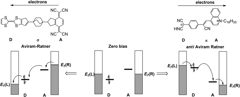 |
| | Fig. 1 Current flow in the Aviram–Ratner (left) and anti-Aviram–Ratner directions in molecular rectifiers. | |
Much of the recent progress in molecular electronics has come in the context of organic systems where a conjugated π system provides the dominant transport channel. However arrays of transition metal ions have much to offer,16 not least because the relative lability of the coordinate bond provides a potent tool for custom design of molecules. The so-called Extended Metal Atom Chains (EMACs), arrays of transition metal ions supported by polydentate ligands, are a case in point: advances in synthetic technique mean that it is now possible to vary systematically both their length (3–11 metal atoms) and composition.17 The major barrier to the full exploitation of these systems is the lack of clear correlations between structure and function, function in this case being the ability to support current flow. Such models are relatively well established in organic electronics where the relationship between the properties of the frontier π orbital domain and current flow is well understood.18,19 The situation is less clear-cut in transition metal ions because the generally poor d–d overlap and strong electron–electron repulsions can lead to a densely populated window around the Fermi level. Systematic trends in conductance have begun to emerge through the experimental measurements of Peng, Hsien and co-workers, who have established its dependence on composition (Cr3, Co3, Ni3, Ru3),20 on chain length (M3, M5)21 and also on the valency of the metals ([Ni5]10+, [Ni5]8+).22 At the same time we23 and others24–26 have begun to explore these properties from a theoretical perspective.
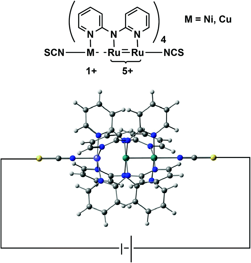
In this paper we address a simple question: what electronic features of an extended metal atom chain do we need to take into account when designing an effective molecular rectifier? As a platform for this study we choose a pair of molecules, Ru2Ni(dpa)4(NCS)2 and Ru2Cu(dpa)4(NCS)2 shown in Fig. 2 (dpa = dipyridylamido), the chloride-capped analogues of which have been synthesised by Peng and co-workers.27 The authors noted that both molecules meet the first requirement of rectification, in so much as they are obviously asymmetric. Moreover, they are somewhat unusual in the context of EMAC chemistry in that their ground states are best formulated as {Ru2}5+ M1+ (M = Ni, Cu) rather than the more common isovalent {M2+}3. The charge separation reflects the substantial electronic differences between late first row (Ni, Cu) and mid second row (Ru) transition metal ions, and suggests that the molecular orbitals should be spatially localised on one side or the other. This, in turn, should offer the potential for substantial current rectification, but which of the two is more effective?
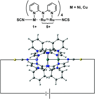 |
| | Fig. 2 Structure of an asymmetric EMAC, Ru2M(dpa)4(NCS)2. | |
Computational methods
All calculations of the gas-phase electronic structure of Ru2M(dpa)4(NCS)2, M = Ni, Cu were performed using the Amsterdam Density Functional package ADF2013![[thin space (1/6-em)]](https://www.rsc.org/images/entities/char_2009.gif) 28 package. A double-ζ Slater-type basis set, extended with a single polarization function (DZP) was used to describe the main group atoms, while ruthenium, copper and nickel were modeled with a triple-ζ basis set with a single polarization function (TZP). Electrons in orbitals up to and including 1s {C, N}, 2p {S}, 2p {Ni, Cu} and 3d {Ru} were considered part of the core and treated in accordance with the frozen core approximation. The local density approximation was employed for the optimizations,29 along with the local exchange–correlation potential of Vosko, Wilk and Nusair30 and gradient corrections to exchange and correlation proposed by Perdew, Becke and Ernzerhof (PBE).31 Scalar relativistic effects were introduced through the zeroth order relativistic approximation (ZORA). Different configurations were defined using the ‘occupations’ key. Transport calculations were performed with the ATK12.8.232,33 package using the LDA functional with the self-interaction correction (SIC) of Perdew and Zunger (LSDA.PZ).34 The methodology combines a density functional theory treatment of the electronic structure with the Keldysh non-equilibrium Green's function approach to simulating coherent transport.35 The scattering region contained the EMAC sandwiched between 6 × 6 layer of the Au (111) surface of the source and the drain, respectively. The sulfur atoms of the two NCS− ligands are located in a hollow site on the Au (111) surface with Au–S distance 2.52 Å. The precise details of the contact geometry remain a significant issue in all transport calculations – the ‘hollow-site’ geometry with a gold–sulfur distance of 2.52 Å (corresponding to a distance of ∼1.9 Å between the sulfur and the surface) adopted here has been established as the global minimum for many examples of sulfur coordination to Au (111)36 and is used in the majority of comparative studies.37 A double-ζ basis set, extended with single polarization function (DZP) was used to describe all atoms except gold which was modelled using a single-ζ basis set, extended with single polarization function (SZP). Core electrons were described by norm-conserving pseudopotentials.38 The electronic structure of the two-probe systems at equilibrium was converged using a 100 Ry mesh cut-off, finite temperature of 300 K at the electrodes. Sampling of the Brillouin zone was performed using a Monkhorst–Pack grid39 with 100 k-points along the transport direction. In the calculation of the transmission spectra and currents, a 5 × 5 grid was used to sample the Brillouin zone, and the bias window was sampled at 0.01 eV intervals. The initial spin density for the two-probe calculations was polarized to be consistent with the net spin densities of the isolated molecules in their gas phase ground states. A full set of Cartesian coordinates for the two-probe system is provided in the ESI (Table S1†).
28 package. A double-ζ Slater-type basis set, extended with a single polarization function (DZP) was used to describe the main group atoms, while ruthenium, copper and nickel were modeled with a triple-ζ basis set with a single polarization function (TZP). Electrons in orbitals up to and including 1s {C, N}, 2p {S}, 2p {Ni, Cu} and 3d {Ru} were considered part of the core and treated in accordance with the frozen core approximation. The local density approximation was employed for the optimizations,29 along with the local exchange–correlation potential of Vosko, Wilk and Nusair30 and gradient corrections to exchange and correlation proposed by Perdew, Becke and Ernzerhof (PBE).31 Scalar relativistic effects were introduced through the zeroth order relativistic approximation (ZORA). Different configurations were defined using the ‘occupations’ key. Transport calculations were performed with the ATK12.8.232,33 package using the LDA functional with the self-interaction correction (SIC) of Perdew and Zunger (LSDA.PZ).34 The methodology combines a density functional theory treatment of the electronic structure with the Keldysh non-equilibrium Green's function approach to simulating coherent transport.35 The scattering region contained the EMAC sandwiched between 6 × 6 layer of the Au (111) surface of the source and the drain, respectively. The sulfur atoms of the two NCS− ligands are located in a hollow site on the Au (111) surface with Au–S distance 2.52 Å. The precise details of the contact geometry remain a significant issue in all transport calculations – the ‘hollow-site’ geometry with a gold–sulfur distance of 2.52 Å (corresponding to a distance of ∼1.9 Å between the sulfur and the surface) adopted here has been established as the global minimum for many examples of sulfur coordination to Au (111)36 and is used in the majority of comparative studies.37 A double-ζ basis set, extended with single polarization function (DZP) was used to describe all atoms except gold which was modelled using a single-ζ basis set, extended with single polarization function (SZP). Core electrons were described by norm-conserving pseudopotentials.38 The electronic structure of the two-probe systems at equilibrium was converged using a 100 Ry mesh cut-off, finite temperature of 300 K at the electrodes. Sampling of the Brillouin zone was performed using a Monkhorst–Pack grid39 with 100 k-points along the transport direction. In the calculation of the transmission spectra and currents, a 5 × 5 grid was used to sample the Brillouin zone, and the bias window was sampled at 0.01 eV intervals. The initial spin density for the two-probe calculations was polarized to be consistent with the net spin densities of the isolated molecules in their gas phase ground states. A full set of Cartesian coordinates for the two-probe system is provided in the ESI (Table S1†).
Results and discussion
Electronic structure at equilibrium
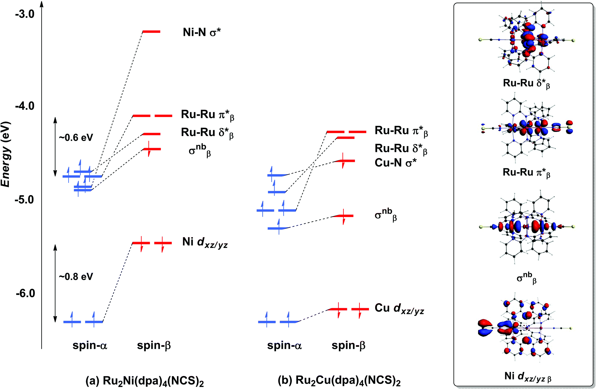
With only minor caveats, the picture of the ground state electronic structure of Ru2Ni(dpa)4(NCS)2 in the gas phase that emerges from our calculations is consistent with the previously published model of Bénard, Rohmer and Peng which predicts a quintet ground state (S = 2).27 The only significant difference is that the perfectly linear (C4 symmetric) Ru2Ni array proves not to be a minimum on the potential energy surface of Ru2Ni(dpa)4(NCS)2: a bent structure with an Ru–Ru–Ni angle of approximately 172° is marginally (0.05 eV) more stable (Table 1). We return to a discussion of the bending and its origins later, but as it has little impact on the electronic structure, at least to first order, we focus the discussion below on the less stable linear isomer. As shown by Bénard, the ground state of Ru2Ni(dpa)4(NCS)2 is best formulated as Ni1+–{Ru2}5+ rather than Ni2+–{Ru2}4+: the Mulliken charges are 0.45, 1.38 and 1.19 for Ni, Ruc and Rut, respectively (Ruc and Rut denote central and terminal, ruthenium centres, respectively) and the Mulliken spin density of 1.08 at nickel is more consistent with a d9 configuration (Ni1+) than d8 (Ni2+). The presence of vacancies in the spin-β components of the Ni–N σ* (dx2−y2) and the Ru–Ru π* and δ* orbitals is apparent in the Kohn–Sham molecular orbital diagram shown in Fig. 3(a). The critical left (Ni)–right (Ru2) localisation of the orbitals of π and δ symmetry is apparent in contour plots in Fig. 3. In contrast the orbitals of σ symmetry show appreciable left–right delocalisation, with the σnb orbital having almost equal amplitudes on Ni dz2 and Rut dz2. The splitting between the spin-α and spin-β components of the different orbitals is particularly relevant to the subsequent discussion of electron transport: the smaller separation between the π*α/β levels (∼0.6 eV) relative to Ni dxz/yz α/β (∼0.8 eV) reflects the stronger electron–electron repulsions in the smaller 3d orbital.
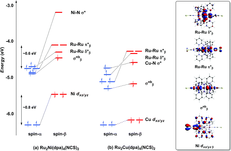 |
| | Fig. 3 Comparison of the frontier Kohn–Sham orbitals (a) for Ru2Ni(dpa)4(NCS)2 and (b) for Ru2Cu(dpa)4(NCS)2. Contour plots are shown for the Ru2Ni(dpa)4(NCS)2 case. | |
Table 1 Computed bond lengths (Å) and angles Ru–Ru–M (°), M = Ni, Cu, Mulliken charges (Q) and spin densities (ρ) and relative energies (eV) of Ru2Ni(dpa)4(NCS)2 and Ru2Cu(dpa)4(NCS)2 in both linear (C4v) and bent (C1) geometries. X-ray data for the Ru2M(dpa)4Cl2 are shown for comparison22
| |
M–Ruc |
Ruc–Rut |
θ
|
M–N |
Ruc–N |
Rut–N |
Q(M) |
Q(Ruc) |
Q(Rut) |
ρ(M) |
ρ(Ruc) |
ρ(Rut) |
E/eV |
|
The terminal Ru and Ni positions in this data set could not be distinguished: the authors note that actual uncertainties in bond lengths are likely to be much higher.
This value represents the average of four distinct Cu–N bond lengths varying between 2.126 and 2.226 Å.
|
| Ru2Ni(dpa)4(NCS)2 (C4v) |
2.43 |
2.37 |
180 |
4 × 2.12 |
4 × 2.06 |
4 × 2.11 |
0.45 |
1.38 |
1.19 |
1.08 |
1.28 |
0.82 |
0.0 |
| Ru2Ni(dpa)4(NCS)2 (C1) |
2.43 |
2.38 |
172.5 |
2.06–2.22 |
2.03–2.09 |
2.08–2.14 |
0.47 |
1.37 |
1.20 |
1.17 |
1.23 |
0.75 |
−0.05 |
| Ru2Ni(dpa)4Cl2a |
2.349(5) |
2.341(4) |
180 |
2.102(3) |
2.012(3) |
2.106(3) |
|
|
|
|
|
|
|
| Ru2Cu(dpa)4(NCS)2 (C4) |
2.58 |
2.35 |
180 |
4 × 2.23 |
4 × 2.06 |
4 × 2.11 |
0.29 |
1.47 |
1.20 |
0.16 |
1.35 |
0.86 |
0.0 |
| Ru2Cu(dpa)4Cl2 |
2.575(3) |
2.246(3) |
180 |
2.173(6)b |
2.046(2) |
2.136(4) |
|
|
|
|
|
|
|
The tendency for the Ru2Ni(dpa)4(NCS)2 species to bend can be traced to the energetic proximity of the occupied σnbβ orbital to the vacant π*β: removing the axial symmetry allows the two to mix, further stabilising the lower-lying orbital (a second order Jahn–Teller distortion). The bending of the Ru2Ni framework also introduces a significant variation in the Ni–N bond lengths (computed values vary between 2.06 and 2.22 Å). It is difficult to validate the prediction of bending against experimental data due to the disorder in the crystal structure of Ru2Ni(dpa)4(Cl)2, but it is possible that the bending is in fact the source of the disorder. What is clear is that the closely related homometallic Ru3 chains are strongly bent for all but the most electron donating terminal ligands, and for very similar electronic reasons.23d
Turning to the copper analogue Ru2Cu(dpa)4(NCS)2, the Cu 3d manifold is now stabilised (relative to Ni) due to the increase in effective nuclear charge and both spin components of the Cu–N σ* orbital are now occupied (Cu1+, d10). This has several consequences for the molecular orbital array, the most obvious being that the distinction between the spin-α and spin-β components of Cu dxz/yz is much reduced compared to Ru2Ni(dpa)4(NCS)2. Moreover, the σnb orbital, with similar amplitudes on Cu and Rut, is stabilised relative to the Ru–Ru π* and δ* orbitals which have only relatively minor contributions from the heterometal. The increased σnb–π* separation reduces the driving force for the bending distortion, and in fact we have been unable to locate a bent local minimum in the Ru2Cu(dpa)4(NCS)2 case: all attempts reverted back to the linear structure. This observation is consistent with the fact that disorder problems were less acute in the crystal structure determination in this case, although the residual variation within the experimental Cu–N bond lengths (2.126–2.226 Å) suggests that the potential energy surface for the bending remains flat.
The electronic structure model developed for the gas phase persists in the device configuration where the molecules are supported between the (111) faces of two bulk gold electrodes (Fig. 4(a and b)). The Mulliken spin densities on the metal centres in Ru2Ni(dpa)4(NCS)2, for example, are very similar to those in the gas-phase (1.15, 1.22 and 0.66 for Ni, Ruc and Rut, respectively compared to values of 1.08, 1.28 and 0.82 in Table 1). The zero-bias transmission spectrum of Ru2Ni(dpa)4(NCS)2 shown in Fig. 4(a) further emphasises the close relationship between the molecule in isolation and in situ between the electrodes: there is a near one-to-one correspondence between the Kohn–Sham eigenvalues of the isolated molecule (Fig. 3(a)) and the position of the resonances in the transmission spectrum. The corresponding transmission spectrum calculated using the PBE functional is shown in ESI, Fig. S2.†
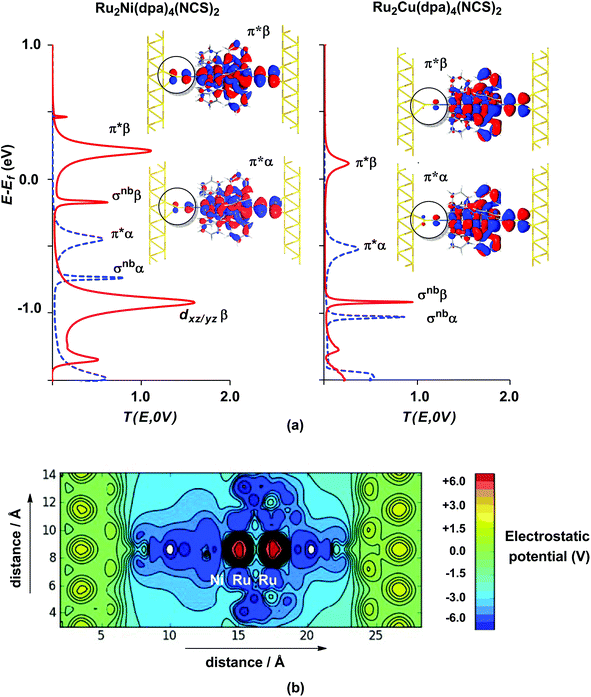 |
| | Fig. 4 Equilibrium electronic structure of Ru2M(dpa)4(NCS)2 in the device configuration where the molecule is supported between the (111) faces of two bulk gold electrodes: (a) zero-bias transmission spectrum and (b) electrostatic difference potential between the self consistent density and that of free atoms. Note that in (a) spin-α levels/channels are shown in blue, spin-β levels/channels in red. All isosurfaces are shown at the same contour level (0.008 au). | |
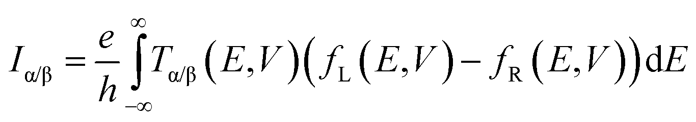
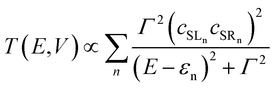
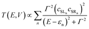
The connection between current flow and the underlying electronic structure is established through the voltage- and energy-dependent transmission function, T(E, V):40
| |  | (1) |
where
fL(
E,
V) and
fR(
E,
V) are the Fermi functions of the left and right electrodes, respectively. The transmission function is computed through:
| | | T(E, V) = tr[ΓLGR†MΓRGRM] | (2) |
where
GRM is the retarded Green's function of the molecular region. Assuming the electrode establishes contact only through the two terminal atoms of the molecule (in this case the sulfur atoms of the left and right NCS ligands), the transmission function can be approximated by:
| |  | (3) |
where
εn is the eigenvalue of the
nth molecular orbital and
cSLn,
cSRn are the coefficients of this orbital at the left and right sulphur atoms.
Γ is the imaginary part of the self energy of the electrode which has the effect of broadening the resonance.
Eqn (3) establishes the critical point that the degree of left–right delocalisation, encapsulated in the product of coefficients
cSLncSRn, determines the magnitude of the transmission function and hence, through
eqn (1), the current. The current is then effectively limited by the size of the smaller of these two coefficients.
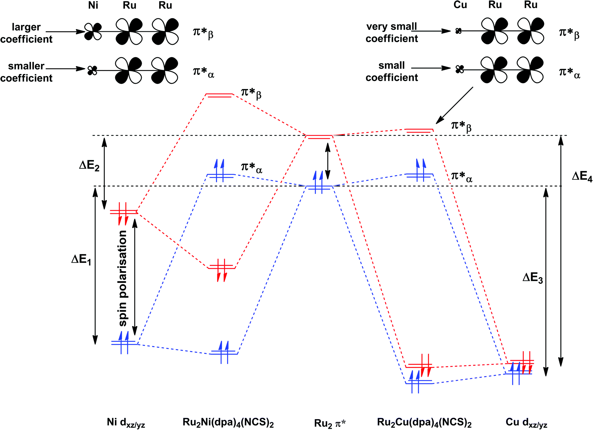
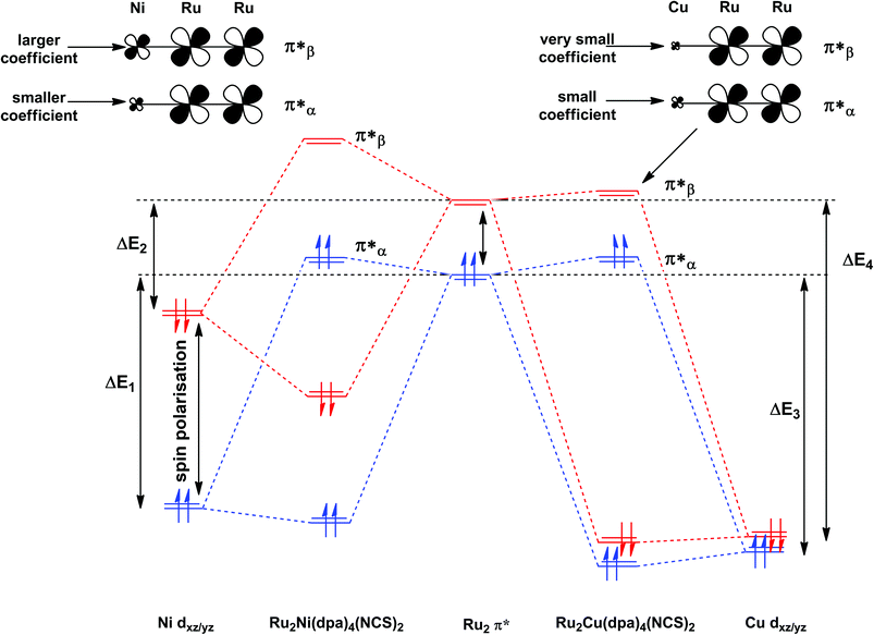
The most significant features of Fig. 4 from an electron transport perspective are the channels which lie close to the Fermi level at zero bias, namely the spin-α and spin-β components of the π* channel which, to a first approximation, are localised on the Ru2 unit and therefore couple more strongly to the right hand electrode (i.e. cSLn < cSRn). The magnitude of the transmission is therefore limited by the value of cSLn, the coefficient on the heterometal end of the molecule: physically, entry/escape of the electron from the Ni/Cu side of the molecule onto the left hand electrode is current-limiting. The spin-β component of π* in the transmission spectrum of Ru2Ni(dpa)4(NCS)2 is strikingly more intense than its spin-α counterpart, indicating a greater degree of left–right delocalisation in the former, a point confirmed by the circled regions in the isosurface plots shown in Fig. 4(a). The spatial difference between π*α and π*β is undeniably small, but it is responsible for a significant increase in transmission. In Ru2Cu(dpa)4(NCS)2, in contrast, it is the lower lying spin-α component of the π* channel that carries the greater intensity, although the difference is less marked in this case. The spin dependence of the delocalisation of the π* channels can be understood in qualitative terms using the spin polarised molecular orbital model shown in Scheme 1. The key feature here is that the orbital arrays for the spin-α (blue) and spin-β (red) manifolds need to be constructed separately, taking account of the energies of the component orbitals (i.e. those on M and those on Ru2) in zeroth order. On the left and centre of the figure are the valence orbitals of isolated Ni1+ (dxz/yz) and {Ru2}5+ (Ru–Ru π*) units, respectively. In both cases the spin-α levels (blue) lie below their spin-β counterparts (red) because all three metal atoms carry positive spin density in the quintet ground state. The splitting between the spin-α and spin-β components of the dxz/yz orbitals on Ni1+ and the π* on {Ru2}5+ (shown as black double headed arrows) is determined by the magnitude of the electron–electron repulsion, which is greater on Ni than on Ru (cf. the discussion of Fig. 3). When the two fragments are allowed to interact, the degree of delocalisation of the π*α and π*β channels will be determined by the zeroth order splittings between the same-spin components of Ni dxz/yz and Ru–Ru π* (ΔE1 and ΔE2) in Scheme 1. As a result of the greater spin polarisation at Ni vs. Ru2, this zeroth order splitting is lowest in the spin-β manifold (ΔE2 < ΔE1 in Scheme 1), and the π*β channel is therefore the more delocalised. In effect, the Au–SCN–Ni junction is more transparent to spin-β electrons than to spin-α. In Ru2Cu(dpa)4(NCS)2 the lower energy of the 3d orbitals on Cu reduces the degree of delocalisation, and hence the transmission, in both spin channels. Moreover, the absence of spin density on Cu (closed-shell d10 configuration) means that the splitting of the spin components is now greater in the {Ru2}5+ π* orbital than in Cu dxz/yz. It is therefore the spin-α components that have the smaller zeroth order separation (ΔE4 > ΔE3) and hence the greater delocalisation (although the difference between π*α and π*β is small).
 |
| | Scheme 1 Origin of the spin-dependence of the delocalisation of the π* channels in Ru2Ni(dpa)4(NCS)2 and Ru2Cu(dpa)4(NCS)2. Red and blue lines denote the spin-β and spin-α manifolds, respectively. | |
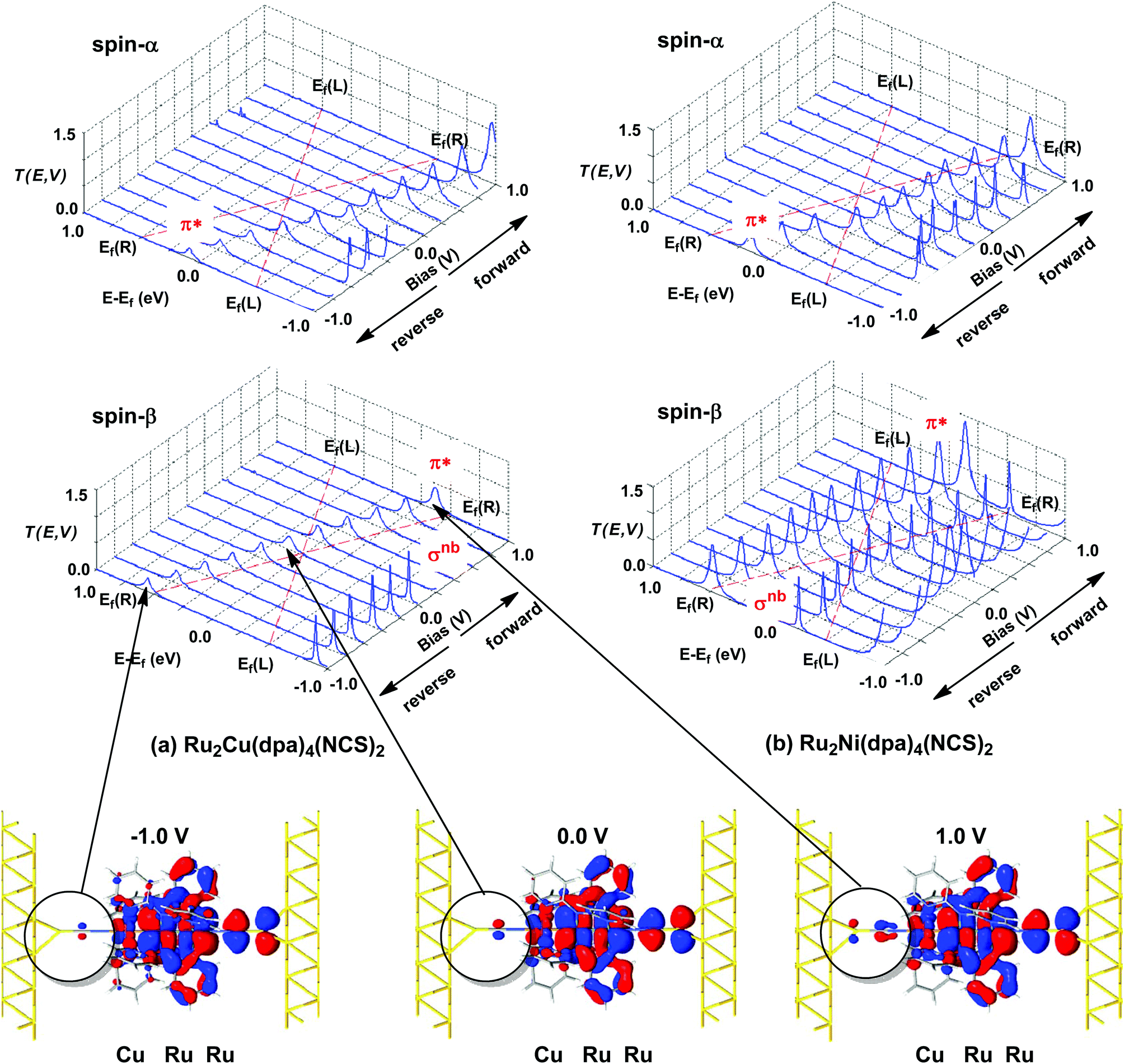
Current–voltage characteristics
The current–voltage curves for Ru2Ni(dpa)4(NCS)2 and Ru2Cu(dpa)4(NCS)2 are compared in Fig. 5, while the voltage dependence of the transmission spectra is summarised in the stack plots in Fig. 6. The Ru2Cu(dpa)4(NCS)2 system provides a convenient reference point for the discussion because in this case current flow in both forward and reverse directions is dominated by the π* channels. Under forward bias the current is carried almost entirely by the spin-β component of the π* channel (spin-filtering efficiency, (Iβ − Iα)/(Iβ + Iα) × 100% = 98%). This channel is localised primarily on the {Ru2} subunit and so it tracks the Fermi level of the right hand electrode, entering the bias window from above at +0.1 V (Fig. 6). The forward current reaches a plateau value of ∼1.0 μA at ∼+0.3 V and then continues to rise slightly as the bias increases further. The reverse bias current, in contrast, is dominated almost entirely by the spin-α component of the π* channel, which lies below the Fermi level at equilibrium and enters the bias window at −0.4 V. The current again reaches a plateau of ∼1.0 μA but then, in contrast to the forward current, tails off at more negative bias. The similar plateau currents in forward and reverse direction correlate with the similar intensities of the π*α and π*β peaks in the transmission spectrum which, in turn, reflect their very similar degrees of left–right delocalisation. The different gradients of the current at higher voltages can also be tracked to the delocalisation of the channel, and specifically now to its dependence on bias. Forward bias stabilises the {Ru2} side of the molecule relative to Cu, and so the zeroth order separation between the orbitals in Scheme 1 (ΔE1, ΔE2) is reduced, leading to greater delocalisation. Conversely, reverse bias stabilises the Cu side, increasing the zeroth order energy gaps and reducing delocalisation. These trends are apparent in Fig. 6(a), where the π* channels (both α and β) increase in intensity on going from left (reverse bias) to right (forward bias). Under forward bias the current-carrying channel therefore becomes more transparent as voltage increases whereas under reverse bias the channel closes off, giving a weak negative differential resistance (NDR) feature.
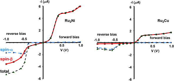 |
| | Fig. 5 Computed current–voltage characteristics for Ru2Ni(dpa)4(NCS)2 and Ru2Cu(dpa)4(NCS)2. Forward bias is defined where VR > VL (i.e. EfR < EfL and the flow of electrons is from Ni to Ru). | |
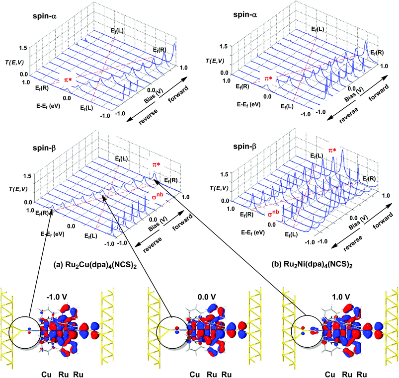 |
| | Fig. 6 Voltage dependence of transmission spectra of (a) Ru2Cu(dpa)4(NCS)2 and (b) Ru2Ni(dpa)4(NCS)2. Isosurface plots for the π*β channel of Ru2Cu(dpa)4(NCS)2 at equilibrium and under forward and reverse bias (±1.0 V), highlighting the increasing left–right delocalisation under forward bias. The bias window is indicated by dashed red lines. | |
Turning to the Ru2Ni(dpa)4(NCS)2 analogue, the forward current is again dominated by the π*β channel, and plateaus at ∼5 μA before increasing further at higher voltage. The 5-fold increase in plateau current compared to Ru2Cu(dpa)4(NCS)2 is a direct result of the spin polarisation of the dxz/yz levels on Ni which enhances the left–right delocalisation of the π*β channel and raises the intensity of the corresponding transmission peak. The behaviour under reverse bias is more complicated because there are now significant contributions to the current from both spin-α and spin-β manifolds. The spin-α current is again carried by the π* channel, which plateaus at ∼2 μA before tailing off to higher bias for exactly the same reasons as discussed above. In the absence of the spin-β component of the current, therefore, the π* manifold could support a rectification ratio of ∼3.0 at biases in excess of 1 V. In the present case, however, the rectification is compromised by the presence of a substantial spin-β component carried by the σnb channel, which also enters the bias window at −0.5 V (Fig. 6(b)).
Conclusions and outlook
The arguments set out in this paper identify the features of electronic structure that can lead to asymmetric current flow. Physical asymmetry of the kind present in both Ru2Ni(dpa)4(NCS)2 and Ru2Cu(dpa)4(NCS)2 is a necessary condition for rectification, but is not sufficient to guarantee substantial rectification ratios. There are in fact three distinct features of the system that combine to afford the observed rectification. (1) The presence of a spin moment, which displaces the spin-α and spin-β components of the π* channel below and above the Fermi, respectively. (2) The localisation of the channel on the Ru2 unit, which means that the current is always limited by the rate of entry/escape from the left hand electrode to the Ni/Cu end of the molecule. This localisation also ensures that both spin components track the potential of the right hand electrode, with the result that the spin-β and spin-α channels carry current under forward and reverse bias, respectively. (3) The presence of a paramagnetic heteroatom (Ni) which tunes the left–right delocalisation of the spin-α and spin-β channels to different extents. The result is that the Au–SCN–Ni junction is more transparent to spin-β electrons than to spin-α, giving a larger current under forward bias. Whilst the calculated rectification ratios are small in these particular systems, the model presented here provides a set of underlying principles that can underpin the rational design of molecules with improved functionality.
Acknowledgements
We acknowledge the EPSRC (UK) for financial support (EP/K021435/1).
Notes and references
-
(a) G. C. Solomon, C. Herrmann and M. A. Ratner, Top. Curr. Chem., 2012, 313, 1 CrossRef CAS;
(b)
J. Jortner, A. Nitzan and M. A. Ratner, in Introducing Molecular Electronics, Springer, Heidelberg, 2005 Search PubMed;
(c) A. R. Rocha, V. M. Garcia-Suarez, S. W. Bailey, C. J. Lambert, J. Ferrer and S. Sanvito, Nat. Mater., 2005, 4, 335 CrossRef CAS PubMed;
(d) W. Y. Kim, Y. C. Choi, S. K. Min, Y. Cho and K. S. Kim, Chem. Soc. Rev., 2009, 38, 2319 RSC.
- K. Stokbro, J. Taylor and M. Brandbyge, J. Am. Chem. Soc., 2003, 125, 3674 CrossRef CAS PubMed.
- D. DeBrincat, O. Keers and J. E. McGrady, Chem. Commun., 2013, 49, 9116 RSC.
-
(a) R. M. Metzger and D. Mattern, Top. Curr. Chem., 2012, 313, 39 CrossRef CAS;
(b) T. Zu, I. R. Peterson, M. V. Lakshmikantham and R. M. Metzger, Angew. Chem., Int. Ed., 2001, 40, 1749 CrossRef.
- G. J. Ashwell, J. R. Sambles, A. S. Martin, W. G. Parker and M. Szablewski, J. Chem. Soc., Chem. Commun., 1990, 1374 RSC.
-
(a) R. Stadler, V. Geskin and J. Cornil, J. Phys.: Condens. Matter, 2008, 20, 374105 CrossRef CAS PubMed;
(b) R. Stadler, V. Geskin and J. Cornil, Adv. Funct. Mater., 2008, 18, 1119 CrossRef CAS.
-
(a) A. Troiisi and M. A. Ratner, J. Am. Chem. Soc., 2002, 124, 14528 CrossRef PubMed;
(b) A. Troisi and M. A. Ratner, Nano Lett., 2004, 4, 591 CrossRef CAS.
- A. Batra, P. Darancet, Q. Chen, J. S. Meisener, J. R. Widawsky, J. B. Neaton, C. Nuckolls and L. Venkataraman, Nano Lett., 2013, 12, 6233 CrossRef PubMed.
-
(a) A. Staykov, D. Nozaki and K. Yoshizawa, J. Phys. Chem. C, 2007, 111, 11699 CrossRef CAS;
(b) Y. Tsuji, A. Staykov and K. Yoshizawa, J. Phys. Chem. C, 2012, 116, 2575 CrossRef CAS;
(c) Y. Tsuji and K. Yoshizawa, J. Phys. Chem. C, 2012, 116, 26625 CrossRef CAS;
(d) A. Staykov, X. Li, Y. Tsuji and K. Yoshizawa, J. Phys. Chem. C, 2012, 116, 18451 CrossRef CAS;
(e) A. Staykov and P. Tzenov, J. Phys. Chem. C, 2013, 117, 13644 CrossRef CAS.
-
(a) Y. Min, J. H. Fang, C. G. Zhong, Z. C. Dong, C. P. Chen and K. L. Yao, Comput. Mater. Sci., 2014, 81, 418 CrossRef CAS PubMed;
(b) L. Zhu, K. L. Yao and Z. L. Liu, Chem. Phys., 2012, 397, 1 CrossRef CAS PubMed.
- Z. Li, J. Zheng, Z. Ni, R. Quhe, Y. Wang, A. Gao and J. Lu, Nanoscale, 2013, 5, 6999 RSC.
-
(a) H. Liu, H. Wang, J. Zhao and M. Kiguchi, J. Comput. Chem., 2013, 34, 360 CrossRef CAS PubMed;
(b) H. Liu, N. Wang, P. Li, X. Yin, C. Yu, N. Gao and J. Zhao, Phys. Chem. Chem. Phys., 2011, 13, 1301 RSC;
(c) H. Liu, J. Zhao, F. Boey and H. Zhang, Phys. Chem. Chem. Phys., 2009, 11, 10323 RSC.
- Z. Li and D. S. Kosov, J. Phys. Chem. B, 2006, 110, 9893 CrossRef CAS PubMed.
- J. Zhao, C. Zeng, X. Cheng, K. Wang, G. Wang, J. Yang, J. G. Hou and Q. Zhu, Phys. Rev. Lett., 2005, 95, 045502 CrossRef.
- A. Aviram and M. A. Ratner, Chem. Phys. Lett., 1974, 29, 277 CrossRef CAS.
-
(a) A. Soncini, T. Mallah and L. F. Chibotaru, J. Am. Chem. Soc., 2010, 132, 8106 CrossRef CAS PubMed;
(b) L. A. Zotti, E. Leary, M. Soriano, J. C. Cuevas and J. J. Palacios, J. Am. Chem. Soc., 2013, 135, 2052 CrossRef CAS PubMed;
(c) Q.-Q. Sun, Y.-J. Li, J.-L. He, W. Yang, P. Zhou, H.-L. Lu, S.-J. Ding and D. W. Zhang, Appl. Phys. Lett., 2013, 102, 093104 CrossRef PubMed;
(d) Y. Matsuura, J. Chem. Phys., 2013, 138, 014311 CrossRef PubMed;
(e) H. Hao, X. Zheng, Z. Dai and Z. Zeng, J. Appl. Phys., 2011, 110, 023702 CrossRef PubMed.
-
(a) J. F. Berry, Struct. Bonding, 2010, 136 Search PubMed;
(b)
J. F. Berry, in Multiple Bonds Between Metal Atoms, ed. F. A. Cotton, C. A. Murillo and R. A. Walton, Springer, New York, USA, 2005 Search PubMed;
(c)
C.-Y. Yeh, C.-C. Wang, C.-h. Chen and S.-M. Peng, in Redox Systems Under Nano-Space Control, ed. T. Hirao, Springer, Berlin, 2006 Search PubMed.
- C. Herrmann, G. C. Solomon and M. A. Ratner, J. Am. Chem. Soc., 2010, 132, 3682 CrossRef CAS PubMed.
- Y. Tsuji, A. Staykov and K. Yoshizawa, J. Phys. Chem. C, 2012, 116, 16325 CAS.
- K.-N. Shih, M.-J. Huang, H.-C. Lu, M.-D. Fu, C.-K. Kuo, G.-C. Huang, G.-H. Lee, C.-h. Chen and S.-M. Peng, Chem. Commun., 2010, 46, 1338 RSC.
-
(a) S.-Y. Lin, I.-W. P. Chen, C.-h. Chen, M.-H. Hsieh, C.-Y. Yeh, T.-W. Lin, Y.-H. Chen and S.-M. Peng, J. Phys. Chem. B, 2004, 108, 959 CrossRef CAS;
(b) I.-W. P. Chen, M.-D. Fu, W.-H. Tseng, J.-Y. You, S.-H. Wu, C.-J. Ku, C.-h. Chen and S.-M. Peng, Angew. Chem., Int. Ed., 2006, 45, 5814 CrossRef CAS PubMed.
- I. P.-C. Liu, M. Bénard, H. Hasanov, I.-W. P. Chen, W.-H. Tseng, M.-D. Fu, M.-M. Rohmer, C.-h. Hsien, G.-H. Lee and S.-M. Peng, Chem. – Eur. J., 2007, 31, 8667 CrossRef PubMed.
-
(a) V. P. Georgiev and J. E. McGrady, Inorg. Chem., 2010, 49, 5591 CrossRef CAS PubMed;
(b) V. P. Georgiev and J. E. McGrady, J. Am. Chem. Soc., 2011, 133, 12590 CrossRef CAS PubMed;
(c) V. P. Georgiev, W. M. C. Sameera and J. E. McGrady, J. Phys. Chem. C, 2012, 116, 20163 CrossRef CAS;
(d) V. P. Georgiev, P. J. Mohan and J. E. McGrady, Chem. Sci., 2012, 3, 1319 RSC;
(e) V. P. Georgiev, P. J. Mohan, D. DeBrincat and J. E. McGrady, Coord. Chem. Rev., 2013, 257, 290 CrossRef CAS PubMed.
- Y. Kitagawa, T. Matsui, Y. Nakanishi, Y. Shigeta, T. Kawakami, M. Okumura and K. Yamaguchi, Dalton Trans., 2013, 42, 16200 RSC.
- D. A. Luzhbin, S. S. Kaun and E. A. Bondar, Metallofiz. Noveishie Tekhnol., 2008, 30, 19 CAS.
-
(a) L. Y. Hsu, Q.-R. Huang and B.-Y. Jin, J. Phys. Chem. C, 2008, 112, 10538 CrossRef CAS;
(b) T. W. Tsai, Q.-R. Huang, S.-M. Peng and B.-Y. Jin, J. Phys. Chem. C, 2010, 114, 3641 CrossRef CAS.
- G.-C. Huang, M. Bénard, M.-M. Rohmer, L.-A. Li, M.-J. Chiu, C.-Y. Yeh, G.-H. Lee and S.-M. Peng, Eur. J. Inorg. Chem., 2008, 11, 1767 CrossRef.
-
(a) G. te Velde, F. M. Bickelhaupt, S. J. A. van Gisbergen, C. Fonseca Guerra, E. J. Baerends, J. G. Snijders and T. Ziegler, J. Comput. Chem., 2001, 22, 931 CrossRef CAS;
(b) C. Fonseca Guerra, J. G. Snijders, G. te Velde and E. J. Baerends, Theor. Chem. Acc., 1998, 99, 391 Search PubMed;
(c)
ADF2013, SCM, Theoretical Chemistry, Vrije Universiteit, Amsterdam, The Netherlands, http://www.scm.com Search PubMed.
-
R. G. Parr and W. Yang, Density Functional Theory of Atoms and Molecules, Oxford University Press, Oxford, 1989 Search PubMed.
- S. H. Vosko, L. Wilk and M. Nusair, Can. J. Phys., 1980, 58, 1200 CrossRef CAS PubMed.
- J. P. Perdew, K. Burke and M. Ernzerhof, Phys. Rev. Lett., 1996, 77, 3865 CrossRef CAS.
-
http://www.quantumwise.com/
.
-
(a) M. Brandbyge, J.-L. Mozos, P. Ordejon, P. Taylor and K. Stokbro, Phys. Rev. B: Condens. Matter, 2002, 65, 165401 CrossRef;
(b) J. M. Soler, E. Artacho, J. D. Gale, A. Garcia, J. Unquera, P. Ordejon and D. Sanchez-Portal, J. Phys.: Condens. Matter, 2002, 14, 2745 CrossRef CAS;
(c) J. Taylor, H. Guo and J. Wang, Phys. Rev. B: Condens. Matter, 2001, 63, 245407 CrossRef.
- J. P. Perdew and A. Zunger, Phys. Rev. B: Condens. Matter, 1981, 23, 5048 CrossRef CAS.
-
(a)
S. Datta, Electron Transport in Mesoscopic Systems, Cambridge University Press, Cambridge, UK, 1997 Search PubMed;
(b)
S. Datta, Quantum Transport: Atom to Transistor, Cambridge University Press, Cambridge, UK, 2005 Search PubMed;
(c) S. Lindsay, Faraday Discuss., 2006, 131, 403 RSC;
(d) R. H. Smit, Y. Noat, C. Untiedt, N. D. Lang, M. C. van Hemert and J. M. van Ruitenbeek, Nature, 2002, 419, 906 CrossRef CAS PubMed;
(e) L. H. Yu, Z. K. Keane, J. W. Ciszek, L. Cheng, M. P. Stewart, J. M. Tour and D. Natelson, Phys. Rev. Lett., 2004, 93, 266802 CrossRef CAS.
- C. Toher and S. Sanvito, Phys. Rev. B: Condens. Matter, 2008, 77, 155402 CrossRef.
-
(a) R. Cohen, K. Stokbro, J. M. L. Martin and M. A. Ratner, J. Phys. Chem. C, 2007, 111, 14893 CrossRef CAS;
(b) H. Liu, C. Yu, N. Gao and J. Zhao, ChemPhysChem, 2010, 11, 1895 CAS;
(c) K. Tagami and M. Tsukuda, J. Phys. Chem. B, 2004, 108, 6441 CrossRef CAS PubMed.
- N. Troullier and J. L. Martins, Phys. Rev. B: Condens. Matter, 1991, 43, 1993 CrossRef CAS.
- H. J. Monkhorst and J. D. Pack, Phys. Rev. B: Solid State, 1976, 13, 5188 CrossRef.
- M. Buttiker, Y. Imry, R. Landauer and S. Pinhas, Phys. Rev. B: Condens. Matter, 1985, 31, 6207 CrossRef.
Footnote |
| † Electronic supplementary information (ESI) available. See DOI: 10.1039/c4qi00038b |
|
| This journal is © the Partner Organisations 2014 |
Click here to see how this site uses Cookies. View our privacy policy here.