 Open Access Article
Insights into Li+ storage mechanisms, kinetics, and reversibility of defect-engineered and functionalized multi-walled carbon nanotubes for enhanced energy storage†
Lingping
Kong
*a,
Yuntong
Zhu
 b,
P. Jason
Williams
c,
Mohamad
Kabbani
c,
Fikile R.
Brushett
 a and
Jennifer L. M.
Rupp
 *bdef
*bdef
aDepartment of Chemical Engineering, Massachusetts Institute of Technology, Cambridge, MA 02139, USA. E-mail: lpkong@mit.edu
bDepartment of Materials Science and Engineering, Massachusetts Institute of Technology, Cambridge, MA 02139, USA. E-mail: jrupp@mit.edu
cShell Catalysts and Technologies LP, Houston, TX 77082, USA
dDepartment of Electrical Engineering and Computer Science, Massachusetts Institute of Technology, Cambridge, MA 02139, USA
eDepartment of Chemistry, Technical University of Munich, 85748 Garching, Germany
fTUM.int. Energy Research, 85748 Garching, Germany
First published on 19th January 2024
Abstract
Lithium-ion batteries (LIBs) are approaching their theoretical energy density limits due to the low capacity of electrode materials, and their charging rates are hindered by the intrinsically slow lithium cation (Li+) storage kinetics in graphite. To overcome these challenges, multi-walled carbon nanotubes (MWCNTs) have been explored as an alternative, offering Li+ storage within the interplanar space between graphene sheets, along with excellent electrical conductivity, and eco-friendliness. However, the defect-rich and functionalized configuration for reversible Li+ storage in MWCNTs is still the subject of debate. Here, we report the design and synthesis of defect-engineered MWCNT-COOH using an acid-treatment method. We conduct an extensive study of Li+ storage mechanisms, kinetics, and reversibility, by employing a suite of electrochemical and structural characterization techniques. The acid treatment successfully introduced extra Li+ storage active sites into MWCNTs, such as oxygen functional groups, structural defects, disordered carbon regions, voids/nanopores in the sidewalls, and uncapped hollow cores, as confirmed by Raman, XPS, and TEM analyses. These multiple active sites enable diverse pathways for Li+ storage, resulting in high overall capacities of up to 855.6 mA h g−1 at 100th cycle at 100 mA g−1, surpassing the pristine MWCNTs with a capacity of 424.1 mA h g−1 under the same conditions. Moreover, defect-engineered MWCNT-COOH exhibits good rate performance, delivering a capacity of 350 mA h g−1 at 500 mA g−1, as well as fast Li+ diffusion coefficients on the order of 10−11 to 10−10 cm2 s−1. The superior electrochemical performance of defect-engineered MWCNT-COOH allows for an increase in the energy density and a decrease in the charging time of LIBs, while maintaining a long lifetime and other performance metrics. Overall, this study provides crucial insights into Li+ storage mechanisms, kinetics, and reversibility of defect-engineered MWCNT materials and their synthesis for future battery designs.
1. Introduction
In the pursuit of zero-carbon emissions, lithium-ion batteries (LIBs) have been continuously considered as a successful clean technology, when recharged only with renewable energy sources.1 LIBs, as electrochemical energy storage devices, can store significant amounts of energy in the form of lithium chemical potential, which can later be discharged to generate electricity. Over the past few decades, LIBs have gained widespread adoption in consumer electronics and electric vehicles, owing to their lightweight, high-energy density, and long cycling lifetime. However, the current LIBs employing graphite anodes, lithium oxide cathodes, and liquid or gel electrolytes are approaching their theoretical energy density limits.1–3 The intrinsically slow Li+ storage kinetics of graphite anodes restrict the charging time of LIBs to several hours.4 To address these challenges, the development of novel materials with fast charge storage kinetics, high-capacity cathodes with high de-lithiation potentials, and high-capacity anodes with low lithiation potentials has proven fruitful in enhancing the energy density and fast-charging capabilities of LIBs.Currently, the LIB market heavily relies on graphite anodes, where graphite serves as a host structure for Li+, allowing the storage of one Li+ for every six carbon atoms in the graphitic plane, with d002 spacing expanding to 0.372 nm. This yields a theoretical capacity of 372 mA h g−1, with flat lithiation curves observed between 0.25–0.01 V vs. Li/Li+.4–6 However, the low theoretical capacity of graphite restricts further improvements in energy density. Another challenge associated with graphite anodes is the occurrence of Li-metal plating when charging rates exceed the Li+ intercalation rate into graphitic planes and the solid-state diffusion rate of Li into the bulk structure of graphite. This leads to reduced coulombic efficiency (CE) and even Li dendrite growth, causing direct shorting of the cell.7 To address the limitations of graphite anodes, numerous alternative anode materials have been investigated in pursuit of high energy and power densities, long-term cycling stability, and improved safety.8 For instance, lithium titanate (Li4Ti5O12), as a zero-strain material during Li+ (de-)intercalation, exhibits the ability to (dis-)charge at high rates of up to 10 C, with over 80% capacity retention and excellent cycling stability.9 However, the high Li+ intercalation potential (1.55 V vs. Li/Li+) and low theoretical capacity (175 mA h g−1, corresponding to Li7Ti5O12) significantly attenuate the energy density. Similar phenomena are observed in other transition metal oxides, such as Nb2O5 and TiO2 anodes.10–12 Silicon (Si), an alloying-type anode material, exhibits a low lithiation potential (below 0.3 V vs. Li/Li+) and a high theoretical capacity of 4212 mA h g−1 (corresponding to Li4.4Si), offering an advantage in terms of high energy density. However, the large volume expansion during Li-alloying (up to 400 vol%) generates significant mechanical stress, leading to material pulverization and continuous reconstruction of solid electrolyte interface (SEI) layer, resulting in rapid capacity fading and poor cycling stability.13 Similar characteristics are observed in other alloying anodes, such as Ge, Sn, and P.14 To overcome these challenges, several strategies have been proposed, including building 3D nanoporous structures and surface coating layers to improve cycling performance.15
Carbonaceous materials are regarded as promising anode candidates for LIBs due to their low lithiation potentials and high Li+ storage capacities. Among them, carbon nanotubes (CNTs) have gained significant attention as Li+ host structures. The electrochemical properties of CNTs are primarily determined by their morphology, structure, and surface chemistry.16–19 Factors such as the number of graphene layers, inner and outer diameters, tube length, alignment, as well as the presence of uncapped or capped ends, lateral defects in the sidewalls, and graphitized structure, all impact their electrochemical performance. Additionally, surface chemistry, including heteroatom doping and functional chemical groups, plays a crucial role in determining their electrochemical behavior. Careful consideration of these factors is essential when designing CNTs-based anodes for LIBs, and further research is needed to fully comprehend and optimize their electrochemical performance.
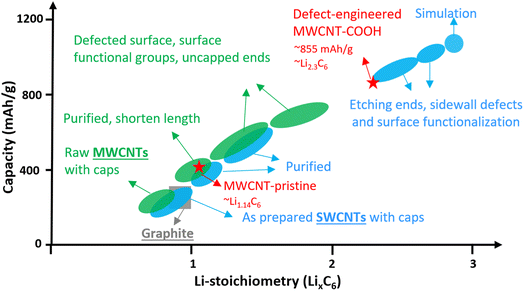
Single-walled carbon nanotubes (SWCNTs) consist of just one graphene sheet rolled into a cylinder, and they can be either metallic or semiconducting depending on their diameter and chirality. Metallic SWCNTs are preferred as Li+ hosts due to their lower Li+ adsorption potentials and 5× higher capacity compared to semiconducting SWCNTs.20 SWCNTs can form bundles with interstitial spaces suitable for Li+ storage.21–24 While, the lithiation potential of well-structured SWCNTs is comparable to graphite, their Li+ density can reach Li1.7C6, corresponding to 632 mA h g−1, surpassing graphite.25 Introducing structural defects, surface functionalization, shortening tube length, and uncapped ends can significantly increase Li+ density in SWCNTs up to Li3C6, corresponding to a remarkable storage capacity of up to 1116 mA h g−1, as shown in Fig. 1 (blue color). These features also facilitate easier Li+ diffusion into the interior space of the tubes.24–27
Multi-walled carbon nanotubes (MWCNTs) are composed of multiple layers of graphene sheets rolled into concentric cylindrical tubes and exhibit excellent electrical conductivity due to dissimilar chirality between the layers. The adjacent graphene layers are spaced approximately 0.34–0.42 nm apart via van der Waals forces, enabling MWCNTs to store Li+ in a similar way to graphite. The Li+ storage capacity of MWCNTs has been enhanced to over 600 mA h g−1 through various methods like ball-milling, high-temperature and/or wet-chemical processing.28–43 The improvements can be attributed to surface functionalization, defect-engineered surfaces, shortened length, and uncapped ends,31,38–42 which are summarized in Fig. 1 (green color). However, the detailed study of Li+ storage processes in defect-engineered MWCNTs and the impact of morphology, structure, and surface chemistry on electrochemical behaviors require further investigation in the field. Understanding the structure–property relationship of defect-engineered MWCNTs is essential to ensure their long-term cycling stability.
To this end, we synthesized defect-engineered MWCNT-COOH by optimizing the acid treatment duration. Microscopic morphology and nanostructure characterization through scanning electron microscopy (SEM), transmission electron microscopy (TEM), and Raman spectroscopy, revealed defected features, including surface structural defects, voids/nanopores in the sidewalls, disordered carbon regions, and uncapped ends. Additionally, X-ray photoelectron spectroscopy (XPS) clearly demonstrated the presence of oxygen functional groups introduced into defect-engineered MWCNT-COOH after acid treatment. Subsequently, we conducted a comprehensive investigation into the influence of these defected features and oxygen functional groups on Li+ storage mechanisms, kinetics, and reversibility, employing electrochemical characterization techniques. A significant finding was that defect-engineered MWCNT-COOH exhibited twice the capacity, reaching to 857 mA h g−1, in comparison to pristine MWCNTs. This increase in capacity can be attributed to the additional active sites resulting from the increased number of defects and voids/nanopores in sidewalls and oxygen functional groups. Moreover, defect-engineered MWCNT-COOH displayed a high Li+ diffusion coefficient of 10−11 to 10−10 cm2 s−1 and demonstrated excellent rate performance, which can be explained by defected structure facilitating Li+ transport. Through material synthesis and fundamental studies on the structure-to-electrochemical properties, we have established a rational approach for the design of defect-engineered MWCNT-COOH as Li+ storage materials. This approach aims to develop functional electrodes that enable high-energy and fast-charging capabilities of LIBs.
2. Experiment
2.1 Preparation of functionalized multi-walled carbon nanotubes
The commercial MWCNTs (diameter 10–30 nm, received from Sigma-Aldrich) were functionalized through chemical oxidation in a mixture of nitric acid (HNO3, 68%) and sulfuric acid (H2SO4, 98%) (v/v = 3![[thin space (1/6-em)]](https://www.rsc.org/images/entities/char_2009.gif) :
:![[thin space (1/6-em)]](https://www.rsc.org/images/entities/char_2009.gif) 7) (Thermo Fisher Scientific) at room temperature (∼22 °C) for various durations. The resulting mixture was quenched in deionized water, filtered, and washed several times until the pH reached ∼7. Subsequently, the acid-treated powders were dried under vacuum at 120 °C. The degree of functionalization was controlled by adjusting the acid-treatment time. The most optimal functionalized sample was referred to as defect-engineered MWCNT-COOH (shortened as MWCNT-COOH in the figures). The as-received commercial MWCNTs were labeled MWCNT-pristine.
7) (Thermo Fisher Scientific) at room temperature (∼22 °C) for various durations. The resulting mixture was quenched in deionized water, filtered, and washed several times until the pH reached ∼7. Subsequently, the acid-treated powders were dried under vacuum at 120 °C. The degree of functionalization was controlled by adjusting the acid-treatment time. The most optimal functionalized sample was referred to as defect-engineered MWCNT-COOH (shortened as MWCNT-COOH in the figures). The as-received commercial MWCNTs were labeled MWCNT-pristine.
2.2 Materials characterization
The morphology and structure of the samples were characterized using a scanning electron microscope (SEM, Zeiss Merlin high-resolution SEM with in-lens secondary electron detector) operating at an accelerating voltage of 7 kV and a working distance of 4.8 mm as well as a transmission electron microscope (TEM, FEI Tecnai) operating at an accelerating voltage of 120 kV. Raman spectroscopy measurements were performed on a Raman spectrometer (HoloLab series 5000, Kaiser Optical Systems) at 532 nm laser excitation. All spectra were collected with 5-time accumulations of 10 s per scan. Crystallinity was evaluated using X-ray diffraction (XRD) patterns acquired with an analytical (X'Pert) diffractometer using Cu-Kα radiation (k = 0.154 nm) at an accelerating voltage of 45 kV and a current of 200 mA, with 2θ range from 5° to 90°. Surface chemistry was characterized using X-ray photoelectron spectroscopy (XPS, Thermo Scientific K-Alpha) with an analyzer pass energy of 200 eV for a low-energy-resolution survey scan and 50 eV for a high-energy-resolution scan. The microstructure of cycled samples was analyzed using a Titan Themis Z G3 Cs-Corrected S/TEM at 60 kV.2.3 Preparation of MWCNTs electrode discs
Before slurry coating electrodes, the MWCNTs materials were thoroughly dried under vacuum at 120 °C overnight. In order to precisely study the Li+ storage mechanism of the MWCNTs, we intentionally avoided using a conductive agent (e.g., carbon black) to prevent the interference at the low cut-off voltage. For electrode preparation, we mixed MWCNTs and polyvinylidene fluoride (PVDF) (purity >99.5%, MTI Corporation) binder in a mass ratio of 9![[thin space (1/6-em)]](https://www.rsc.org/images/entities/char_2009.gif) :
:![[thin space (1/6-em)]](https://www.rsc.org/images/entities/char_2009.gif) 1, using N-methyl pyrrolidinone (NMP) (anhydrous, purity >99.5%, Sigma-Aldrich) as the solvent. After magnetic stirring for 2 hours, the slurry was spread onto a copper foil (purity ≥99.8%, MTI Corporation) using a Mini tape casting coater (MSK-AFA-HC100, MTI Corporation). The resulting wet film was dried at 100 °C under a vacuum of 30′′ Hg and then punched into electrode discs with a diameter of 14 mm. The areal mass loading of MWCNTs was estimated to be ca. 0.7–1.0 mg cm−2.
1, using N-methyl pyrrolidinone (NMP) (anhydrous, purity >99.5%, Sigma-Aldrich) as the solvent. After magnetic stirring for 2 hours, the slurry was spread onto a copper foil (purity ≥99.8%, MTI Corporation) using a Mini tape casting coater (MSK-AFA-HC100, MTI Corporation). The resulting wet film was dried at 100 °C under a vacuum of 30′′ Hg and then punched into electrode discs with a diameter of 14 mm. The areal mass loading of MWCNTs was estimated to be ca. 0.7–1.0 mg cm−2.
2.4 Assembling coin cells
CR2032 coin cell cases were purchased from Guangdong Canrd New Energy Technology, China. Coin cells were assembled in an Argon-filled glove box (Innovative Technology Pure Lab Glove Box) with a water/oxygen content <1 ppm. The Li discs with a diameter of 15.6 mm and a thickness of 560 μm (Guangdong Canrd New Energy Technology, China) were used as the counter and reference electrodes. 1 M lithium hexafluorophosphate (LiPF6) in ethylene carbonate (EC)/ethyl methyl carbonate (EMC) with 50/50 (v/v) (Sigma-Aldrich) was used as the electrolyte without any additives. Celgard-2500 (Celgard) was employed as the separator.2.5 Electrochemical measurements
All the electrochemical measurements were conducted using a VMP-300 Potentiostat (Biologic, USA) at ∼22 °C. The current density and specific capacity were calculated based on the mass of the active materials, and the working potential of the MWCNT electrodes was set between 0.005–3.0 V (vs. Li/Li+). Cyclic voltammetry (CV) test was carried out at a scan rate of 1 mV s−1 between 0.005 and 3 V for 100 cycles. Scan-rate test was performed at different scan rates ranging from 0.5 to 20 mV s−1. The relationship between the peak current (i, mA) and scan rate (ν, mV s−1) is assumed to follow the power-law equation:| i = aνb | (1) |
2.6 GITT test
To study the Li+ diffusion behavior of different MWCNTs, the galvanostatic intermittent titration technique (GITT) was employed. Prior to the GITT measurements, the cells were discharged/charged for 100 cycles at a constant current density of 100 mA g−1. During the GITT, a galvanostatic current pulse was passed through the cell (discharged for 10 minutes at 100 mA g−1), and the relaxation voltage curve was recorded with a relaxation time of 60 minutes. Assuming negligible self-discharge, the voltage decay during cell relaxation was attributed to the diffusion-controlled process, signifying the recovery of a homogeneous lithium concentration throughout the solid. The Li+ diffusion coefficient (DLi+) can be estimated based on Fick's second law (1): | (2) |
3. Results and discussion
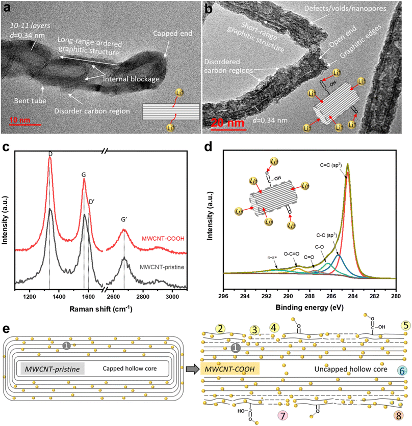
High-resolution transmission electron microscopy (HR-TEM) imaging is used to characterize the morphology and structural changes of MWCNTs during acid treatment. In the pristine state (Fig. 2a), MWCNT-pristine exhibits a multiwalled-tubular structure with long-range graphitic ordering, comprising approximately 10–11 graphene layers with a capped end. The average outer and inner diameters of the nanotubes are ∼12 and 5 nm, respectively, and the distance between adjacent graphene layers is calculated to be ∼0.34 nm using line profile of the HR-TEM image (inserted in Fig S1f†). Surprisingly, MWCNT-pristine, received from the vendor, displays some unexpected disordered carbon regions lacking d-spaced graphene layers and internal blockages consisting of 2–3 graphene layers across the tube. Upon acid treatment, defect-engineered MWCNT-COOH (Fig. 2b) exhibits uncapped ends and an overall increase in surface roughness. The acid treatment not only unzips the nanotube ends but also disrupts the long-range graphitic ordering, causing damage to the exterior graphene layers. This results in the formation of lateral defects in benzene rings, disordered carbon regions, and voids/nanopores in sidewalls, along with the introduction of oxygen functional groups (confirmed with XPS, as detailed below). Despite these changes, short-range ordered regions consisting of a few graphene layers with an interlayer distance of ∼0.34 nm still remained, facilitating rapid electron transport along the axial direction of the tube. Microscopic morphology examination through SEM and low-magnification TEM in Fig. S1† reveals that both MWCNT-pristine and defect-engineered MWCNT-COOH consist of randomly and loosely tangled tubes, with lengths of roughly 10–20 μm. The crystallinity is probed using X-ray diffraction (XRD, in Fig. S2†), showing a lattice constant of ∼0.345 nm, which aligns with the TEM findings. More detailed discussions can be found in ESI.† We hypothesize that the uncapped ends may promote the use of the hollow inner cores for Li+ diffusion,40 which, in turn, impact the reversible capacity and observed kinetics.Raman spectroscopy is used to characterize structural defects and graphitic sizes of MWCNTs. In Fig. 2c, all the Raman peak positions (D and D′ bands, G and G′ bands) remain unchanged when comparing MWCNT-pristine and defect-engineered MWCNT-COOH, but the intensity ratio of Raman peaks shows differences. Specifically, ID/IG, IG′/IG, and IG′/ID are calculated and analyzed as presented in Table S1.† The first-order G band (centered at ∼1580 cm−1) originates from the in-plane stretching vibrations of sp2-bonded carbon atoms in the graphene layer, while the second-order G′ band (centered at ∼2670 cm−1) originates from the tangential mode of the same vibrations.43,44 Consequently, the relative intensity of the G′ and G bands (IG′/IG) can be used to estimate the degree of graphitic ordering property in MWCNTs. The disorder-induced D band has centered at ∼1350 cm−1 which is about half of the frequency of the G′ band, and D′ band has centered at ∼1615 cm−1 arising from defect-assisted intervalley scattering process. This phenomenon can be attributed to double resonance of sp3-hybridized carbon in the disordered carbon regions.44,45 Furthermore, the structural defect density and the degree of graphitization of nanotubes can be evaluated from ID/IG and IG′/ID, respectively.44–47 After acid treatment, defect-engineered MWCNT-COOH shows an increased ID/IG (increased by ∼20%) and decreased IG′/IG and IG′/ID (decreased by ∼30–40%) compared to MWCNT-pristine. Acid treatment of MWCNTs breaks the long-range ordered graphitic structure, reduces the graphitization degree, generates structural defects, and forms disordered carbon regions, all of which are consistent with the TEM analysis in Fig. 2b.
The surface chemistry is characterized by X-ray photoelectron spectroscopy (XPS). The high-resolution C 1s spectra of defect-engineered MWCNT-COOH and MWCNT-pristine are deconvoluted using a Gaussian function in Fig. 2d and S3b,† respectively. The Gaussian deconvoluted spectra include a main peak at 284.46 eV for C![[double bond, length as m-dash]](https://www.rsc.org/images/entities/char_e001.gif) C (attributing to a sp2-carbon in graphitic structure), a low-intensity peak at 285.36 eV for C–C (attributing to sp3-hybridized carbon atoms), and other peaks at 286.31 eV (C–O), 287.49 eV (C
C (attributing to a sp2-carbon in graphitic structure), a low-intensity peak at 285.36 eV for C–C (attributing to sp3-hybridized carbon atoms), and other peaks at 286.31 eV (C–O), 287.49 eV (C![[double bond, length as m-dash]](https://www.rsc.org/images/entities/char_e001.gif) O), 289.10 eV (O–C
O), 289.10 eV (O–C![[double bond, length as m-dash]](https://www.rsc.org/images/entities/char_e001.gif) O), and 290.90 eV (plasmon π–π*).48 After area fitting for different carbon chemical bonds, the atomic ratio of different carbon chemical bonds is calculated and presented in Table S2.† Furthermore, the survey spectra of defect-engineered MWCNT-COOH and MWCNT-pristine only show C 1s and O 1s in Fig. S3a.† The atomic ratio of oxygen to carbon in defect-engineered MWCNT-COOH is ∼0.119, which is ∼10× that of MWCNT-pristine. Additionally, the high-resolution O 1s spectra are deconvoluted in Fig. S3c and d† for the interpretation of the C 1s, and more O double bonds are observed in defect-engineered MWCNT-COOH. Comparing with MWCNT-pristine, defect-engineered MWCNT-COOH exhibits a lower content of C
O), and 290.90 eV (plasmon π–π*).48 After area fitting for different carbon chemical bonds, the atomic ratio of different carbon chemical bonds is calculated and presented in Table S2.† Furthermore, the survey spectra of defect-engineered MWCNT-COOH and MWCNT-pristine only show C 1s and O 1s in Fig. S3a.† The atomic ratio of oxygen to carbon in defect-engineered MWCNT-COOH is ∼0.119, which is ∼10× that of MWCNT-pristine. Additionally, the high-resolution O 1s spectra are deconvoluted in Fig. S3c and d† for the interpretation of the C 1s, and more O double bonds are observed in defect-engineered MWCNT-COOH. Comparing with MWCNT-pristine, defect-engineered MWCNT-COOH exhibits a lower content of C![[double bond, length as m-dash]](https://www.rsc.org/images/entities/char_e001.gif) C (by ∼55.33%) and a higher content of C–C, C–O, C
C (by ∼55.33%) and a higher content of C–C, C–O, C![[double bond, length as m-dash]](https://www.rsc.org/images/entities/char_e001.gif) O and O–C
O and O–C![[double bond, length as m-dash]](https://www.rsc.org/images/entities/char_e001.gif) O, indicating the successful introduction of disordered and defected carbon regions and oxygen function groups after acid treatment.
O, indicating the successful introduction of disordered and defected carbon regions and oxygen function groups after acid treatment.
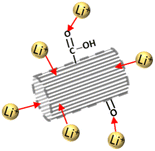
The major structural and chemical findings related to defect-engineered MWCNT-COOH and MWCNT-pristine are summarized in Table 1 and Fig. 2e, listing the potential Li+ storage active sites. Compared to MWCNT-pristine, defect-engineered MWCNT-COOH exhibits a great number of Li+ storage active sites, including ② disordered carbon regions, ③ lateral structure defects, ④ voids/nanopores, ⑤ the broken graphitic edges created by unzipping the caps, ⑥ uncapped hollow-inner cores, ⑦ oxygen functional groups (–COOH and –OH groups), ⑧ unstable surface carbon layer, as well as ① graphitic layers. These additional active sites hold promise for increasing Li+ storage capacity, but a thorough understanding of the Li+ storage mechanism, kinetics, reversibility, and the effect of uncapped hollow cores is necessary.
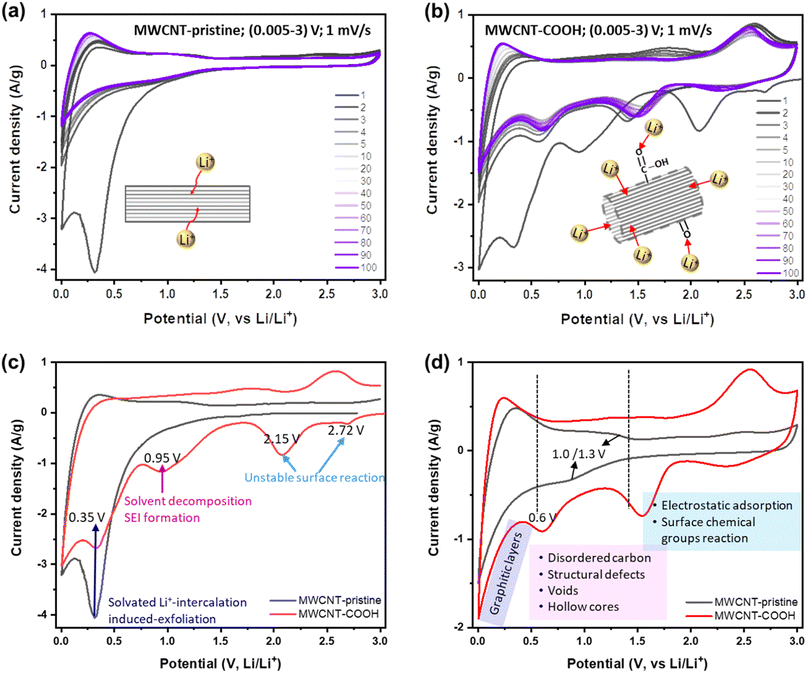
To this end, Li+ storage mechanisms, kinetics, and reversibility in different structurally and chemically engineered MWCNTs have been investigated using various electrochemical techniques. Fig. 3a and b display the CV curves of MWCNT-pristine and defect-engineered MWCNT-COOH cycled at the scan rate of 1 mV s−1 for 100 times, respectively. In the 1st cycle, both samples exhibit a higher capacity for the cathodic process compared to the anodic process, indicating significant capacity loss due to the irreversible reactions. However, in subsequent cycles, both MWCNT-pristine and defect-engineered MWCNT-COOH exhibit reversible Li+ storage reactions. To gain insights into the impact of different structural and chemical features on irreversible reactions in the 1st cycle, the 1st CV curves of MWCNT-pristine and defect-engineered MWCNT-COOH are compared in Fig. 3c, discharging from the open-circuit voltage (OCV). Defect-engineered MWCNT-COOH exhibits a higher OCV (∼3.05 V) than MWCNT-pristine (∼2.78 V) due to the presence of surface oxygen functional groups introduced by acid-treatment.31,42,49 Notably, cathodic peaks at ∼2.72, 2.15, and 0.95 V are observed for defect-engineered MWCNT-COOH, but not for MWCNT-pristine, which may be attributed to the electrochemically irreversible reactions of oxygen functional groups with Li+,49 irreversible Li+ trapping in structural defects, organic carbonate solvent decomposition and SEI layer formation on both interior and exterior surfaces.17,25,49,50 However, SEI-related reduction peak at around 0.95 V for MWCNT-pristine is not as distinct and might have been obscured by the high-intensity peak at ∼0.35 V. This is likely because only the exterior surface is available for SEI, and the interior surface in the capped hollow cores does not contribute to this process, as discussed in the next session. A broad cathodic peak at ∼0.35 V with no corresponding anodic peak is observed in both samples, corresponding to solvated Li+-intercalation-induced exfoliation of unstable graphitic layers on the surface, which has been confirmed by evidence of carbon fragments on the Celgard separator in Fig. S4.† The stresses induced by intercalation between the graphitic layers in the sidewalls can cause the weak van der Waals interaction between the graphene layers to break, leading to exfoliation. This phenomenon has been also observed in MWCNTs with an inner core diameter of 10 nm and a wall thickness of 5 nm using EC (ethylene carbonate)-based electrolyte.51 Therefore, the large capacity loss in the 1st cycle is related to a series of electrochemically irreversible reactions, contingent upon the morphology, structure, and surface chemistry of MWCNTs.
After the 1st cycle, MWCNT-pristine and defect-engineered MWCNT-COOH demonstrate reversible Li+ storage processes but distinct voltage profiles due to their different surface chemistry and microstructure. To delve deeper into these disparate Li+ storage mechanisms, the 5th CV curves are compared in Fig. 3d. MWCNT-pristine shows a sharp reduction tail near 0.005 V and a broad oxidation hump at around 0.25 V, arising from Li+ intercalation/extraction into/from the interplanar space between graphene sheets (graphitic layers). Additionally, MWCNT-pristine exhibits a pair of reduction/oxidation plateaus at approximately 1.0/1.3 V, attributed to Li+ storage in structural defects and disordered carbon (observed by TEM, Raman, and XPS). Furthermore, MWCNT-pristine reveals a quasi-rectangular region between 1.5-3.0 V, featuring a low-capacity contribution from electrostatic adsorption of Li+ on the surface area and possibly a faradaic reaction of Li+ with the low content of oxygen functional groups (oxygen content 1.38 atm% confirmed by XPS). In contrast, defect-engineered MWCNT-COOH exhibits multiple Li+ storage processes due to the introduction of multiple active sites through acid treatment. In addition to Li+ intercalation/extraction into/from graphitic layers below 0.5 V, a higher capacity-contribution occurs from 0.5–3.0 V. Specifically, defect-engineered MWCNT-COOH, with a confirmed oxygen content of 10.64 atm% via XPS, demonstrates broad cathodic/anodic peaks between 1.5–3.0 V, indicating reversible faradaic reactions between Li+ and oxygen functional groups, resulting in the generation of Li carboxylic salt –COO(Li) and/or –O(Li).31,52 Additionally, a reduction peak at ∼0.6 V suggests Li+ diffusion/adsorption into the uncapped hollow cores, while Li+ extraction from the uncapped hollow cores can occur at any voltage greater than 0.6 V.28,33 We note that further follow-up investigation is required to understand the Li chemical state inside the hollow cores. Li+ doping into amorphous carbon regions, surface defects, and graphitic edges, and the accommodation of Li+ in the voids/nanopores may take place within 0.5–1.5 V with a certain likelihood. A similar group of peaks has been observed in SWCNTs purified with acid treatment and physical processing.25
Furthermore, a voltage hysteresis is observed in Li+ storage/extraction in/from both MWCNT-pristine and defect engineered MWCNT-COOH, a common phenomenon in carbon-based anodes, such as MWCNTs,25,29,34,42 SWCNTs,53 hard carbons,24 and soft carbons.24 This is due to the high barrier of Li+ extraction processes. For instance, Li+ intercalation into graphitic layers occurs below 0.5 V, while, Li+ extraction from the graphitic layers can occur gradually at any voltage above 0.005 V, but mainly below 0.5 V. The voltage hysteresis of Li+ intercalation/extraction into/from graphitic layers is shown in Fig. S5.† In the 1st cycle, defect-engineered MWCNT-COOH exhibits a larger voltage hysteresis (∼0.45 V) than MWCNT-pristine (∼0.35 V), due to its higher content of defects and oxygen functional groups. However, the Li+ extraction potential of defect-engineered MWCNT-COOH decreases to ∼0.21 V after 100 cycles, indicating that the structural defects promote Li+ extraction from graphitic layers. Additionally, Li+ extraction from inner cores also presents a high barrier (intercalation/extraction potentials at ∼0.6/1.8 V) in Fig. 3b, which may be due to the strong coupling Li+ inside the cores and/or the high Li+ diffusion resistance at the uncapped ends caused by Li+ doping at the tube edges. The peak of Li+ extraction from the inner cores at ∼1.8 V flattens during cycles, suggesting that Li+ might be smoothly extracted from the inner cores at any voltage above 0.6 V.
To better understand the Li+ storage kinetics in defect-engineered MWCNT-COOH, scan-rate tests are performed, with scan rates ranging from 0.5 to 20 mV s−1, corresponding to discharge times ranging from 100 to 2.5 minutes, as shown in Fig. 4a. Based on the main cathodic processes, we classify three distinct Li+ storage processes including: peak I at 0.005 V, associated with Li+ intercalation into graphitic layers, peak II at ∼0.6 V, related to Li+ adsorption in defects, voids, and hollow cores, and peak III at ∼1.6 V, linked to the Li+ reaction with oxygen-containing chemical groups. The linearly fitted plots for these three redox peaks, according to eqn (1), are presented in Fig. 4b. The obtained b values are about 0.51, 0.80, and 0.83 for peak I, II, and III, respectively. This indicates that Li+ intercalation into graphitic layers (peak I) is mainly governed by solid-state diffusion. On the other hand, Li+ storage in defects, voids, and hollow cores (peak II), as well as Li+ reaction with oxygen functional groups (peak III), exhibit a combination of diffusion-controlled process and surface-controlled capacitive behavior. The active sites and corresponding reaction peaks are depicted in Fig. 4c. For comparison, the scan-rate test results of MWCNT-pristine and the corresponding calculated b values are given in Fig. S6.† It is evident that the defected structure and surface functional groups contribute to the overall improvement in Li+ storage kinetics. The lower charge-transfer resistance of defect-engineered MWCNT-COOH electrode (after cycling), compared to MWCNT-pristine electrode, can further explain the fast charge transfer kinetics by Electrochemical impedance spectroscopy test in Fig. S7.†
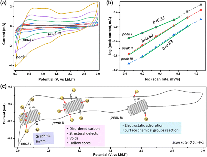 | ||
| Fig. 4 (a) Scan-rate tests of defect-engineered MWCNT-COOH from 0.5–20 mV s−1, (b) the calculated b-value at different peaks, and (c) the active sites and the corresponding reaction peaks. | ||
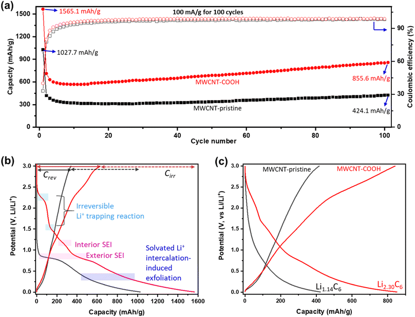
The Li+ storage capacity, reversibility, and cycling stability of MWCNTs are studied using GCD. The discharge capacity (related to Li+ storage capacity) and coulombic efficiency (CE) vs. cycle number at a current density of 100 mA g−1 are shown in Fig. 5a. Selected GCD curves are presented in Fig. S8.† Defect-engineered MWCNT-COOH exhibits a significantly higher capacity, about 2 times of MWCNT-pristine, attributed to the multi-active sites as shown in Fig. 2e. In the initial cycles, both materials experience a capacity decrease: Defect-engineered MWCNT-COOH decreased from 1565.1 mA h g−1 to 568 mA h g−1 at the 10th cycle; MWCNT-pristine decreased from 1027.7 mA h g−1 to 309 mA h g−1 at 17th cycle. The decrease in capacity can be assigned to irreversible side reactions and ohmic resistance. However, in subsequent cycles, both materials display a capacity increase: defect-engineered MWCNT-COOH increased to 855.6 mA h g−1 and MWCNT-pristine increased to 424.1 mA h g−1 at 100th cycle, which can be explained by the electro-activation processes (for more details, refer to Fig. S9†). Compared to MWCNT-pristine, the defect-engineered MWCNT-COOH shows an overall higher CE, indicating improved Li+ storage efficiency due to the defected structure and functionalized surface. Even after 500 cycles at 500 mA g−1, defect-engineered MWCNT-COOH maintained a capacity retention at ∼88.2%, as shown in Fig. S9b.†
To further investigate the irreversible-electrochemical processes in the 1st cycle, Fig. 5b compares the 1st discharge–charge curves of defect-engineered MWCNT-COOH and MWCNT-pristine. Defect-engineered MWCNT-COOH delivers a higher overall discharge capacity of ∼1565.1 mA h g−1, a higher reversible capacity (Crev) of 626.1 mA h g−1, and a higher irreversible capacity (Cirr) of ∼939.0 mA h g−1 than MWCNT-pristine (overall discharge capacity of ∼1027.7 mA h g−1, a Crev of 340.2 mA h g−1, and a Cirr of ∼687.5 mA h g−1). The additional active sites in defect-engineered MWCNT-COOH (as shown in Fig. 2e) not only enhance reversible Li+ storage but also contribute to more irreversible side reactions, such as electrolyte decomposition, SEI formation on the exterior and interior surface of the carbon nanotubes, irreversible Li+ trapping, and solvated Li+ intercalation-induced exfoliation. As a result, the 1st cycle exhibits low CE of 40.0% and 33.1% for defect-engineered MWCNT-COOH and MWCNT-pristine, respectively. However, in both materials, CE increases to over 80% in the 2nd cycle and gradually increases to over 98% after around 20 cycles, indicating a gradually stabilizing electrochemical system.
Fig. 5c provides a comparison of the different reversible Li+ storage processes in defect-engineered MWCNT-COOH and MWCNT-pristine. MWCNT-pristine shows two main Li+ storage processes: a steep slope region between 2–0.5 V related to Li+ storage in the amorphous region and initial defects, and a flat slope region below 0.5 V associated with Li+ intercalation into graphitic layers. In contrast, defect-engineered MWCNT-COOH exhibits multiple Li+ storage processes, including Li+ reactions with surface chemical groups, Li+ doping in defects and accommodation in voids and storage in amorphous carbon regions, Li+ diffusion into hollow cores, and Li+ intercalation into graphitic layers, resulting in a high reversible capacity of 855.6 mA h g−1 at the 100th cycle. To directly compare Li-content with graphite and other published data, Li+ storage capacity is converted to Li-intensity (regardless of the O content). Defect-engineered MWCNT-COOH exhibits a higher Li-intensity of Li2.30C6 than MWCNT-pristine (Li1.14C6) and graphite (Li1.0C6), and suppresses the achievements reported in similar MWCNTs as compared in Fig. 1. The higher Li+ storage capacity and Li-intensity in defect-engineered MWCNT-COOH are attributed to the multiple active sites. Thus, we proposed that optimizing the morphology, microstructure, and surface chemistry of MWCNTs can lead to an improvement in the reversible Li+ storage capacity.
High-angle annular dark-field scanning transmission electron microscopy (HAADF-STEM) is utilized to characterize the changes of morphology and structure before and after lithiation. Fig. 6a and b show the exterior and interior SEI in defect-engineered MWCNT-COOH with the uncapped ends. Notably, the interior SEI with ∼20 nm thickness preferentially blocks the end of the hollow core. In contrast, Fig. 6c shows MWCNT-pristine with a capped end, where only exterior SEI is observed, and the hollow core remains clean after cycling. The uncapped structure facilitates Li+ diffusion along the hollow core, resulting in a high capacity. However, it also contributes to irreversible reactions associated with the formation of interior SEI, leading to an unavoidable irreversible capacity. This phenomenon could also explain why the peak at 1.8 V in Fig. 3b becomes flat within 20 cycles.
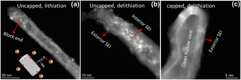 | ||
| Fig. 6 HAADF-STEM images of defect-engineered MWCNT-COOH with (a) fully lithiation and (b) fully de-lithiation, (c) MWCNT-pristine with fully de-lithiation. | ||
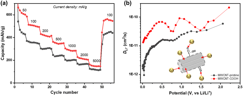
To assess the rate performance and the fast-charging capabilities of defect-engineered MWCNT-COOH, a fresh coin cell with two electrodes (Li-metal as counter/reference electrode) is tested at different current densities ranging from 50 to 5000 mA g−1, as shown in Fig. 7a. The selected discharge–charge curves at each current density are presented in Fig. S10.† Defect-engineered MWCNT-COOH exhibits discharge capacities of ∼600, 500, 420, 350, 290, and 200 mA h g−1 at current densities of 50, 100, 200, 500, 1000, and 2000 mA g−1, respectively. These capacities surpass those of MWCNT-pristine, graphene-carbon nanotubes composite, graphene-wrapped carbon nanotubes, and nano-drilled MWCNTs.35,54–56 Converting the current density to discharge time, defect-engineered MWCNT-COOH delivered a capacity of ∼350 mA g−1 in ∼42 minutes and a capacity of ∼290 mA g−1 in ∼17 minutes. The excellent rate performance depicted in Fig. 7a provides evidence that defect-engineered MWCNT-COOH holds the potential to decrease charging time in future full-cell configurations. It is noteworthy that even after high-rate testing, the discharge capacity of defect-engineered MWCNT-COOH can still recover to ∼550 mA h g−1 at 100 mA g−1. The excellent rate performance of defect-engineered MWCNT-COOH can be attributed to its defected structure and functionalized surface with a low energy barrier, resulting in rapid Li+ storage kinetics. However, it is essential to consider that Li-stripping and plating kinetics at the Li-metal electrode, especially at high current densities, may also affect the Li+ storage performance of MWCNTs, which means that rate performance could be underestimated with the two-electrode configuration.
Li+ diffusion coefficient (DLi+) is a crucial parameter in understanding the diffusion kinetics of Li+, and it can be used as an alternative method to elucidate diffusion process. Here, we employ the galvanostatic intermittent titration technique (GITT) to investigate DLi+ at different states of discharge. Fig. 7b shows the log-scale representation of DLi+ as a function of potential, and additional details on GITT measurements can be found in Fig. S12.† Both defect-engineered MWCNT-COOH and MWCNT-pristine exhibit changes in DLi+ during discharge, indicating varying Li+ diffusivity with lithiation degree. When the potential is below 0.5 V, corresponding to Li+ intercalation into graphitic layers, DLi+ decreases continuously for both materials due to steric factors and electrostatic repulsive interactions between neighboring Li+ as more Li+ intercalates into the graphitic layers. However, the DLi+ of defect-engineered MWCNT-COOH (ranging from 10−11–10−10 cm2 s−1) is about one order of magnitude higher than that of MWCNT-pristine. We propose that defects/voids enhance Li+ diffusion into the graphitic layers. These findings suggest that defect engineering may be an effective strategy for improving Li+ diffusivity in MWCNTs.
4. Conclusion
In summary, this study investigated the potential of defect-engineered MWCNT-COOH as an anode material, aiming to address the limitations of energy density and charge rate in current LIBs with graphite anodes. Through a one-step acid-treatment method, we successfully introduced oxygen functional groups onto the surface, unzipped the ends, and partially transformed the ordered graphitic structure into a disordered and defected microstructure with voids/nanopores in sidewalls. As a result, additional Li+ storage active sites were created, including oxygen functional groups, uncapped inner hollow cores, disordered carbon regions, structural defects, and voids/nanopores. We further investigated the impact of these structural and chemical features on electrochemical processes of defect-engineered MWCNT-COOH, revealing multiple-active sites contributing to improved reversible Li+ storage capacity of up to 855.6 mA h g−1 (at 100 mA g−1) after 100 cycles. These active sites enabled various reversible Li+ storage processes, such as Li+ reaction with oxygen functional groups, Li+ doping in defects and accommodation in voids, Li+ storage in amorphous carbon regions, Li+ diffusion into hollow cores, and Li+ intercalation into graphitic layers. Moreover, defect-engineered MWCNT-COOH demonstrated excellent rate performance, delivering a capacity of 350 mA h g−1 at 500 mA g−1, and a fast Li+ diffusion coefficient of 10−11 to 10−10 cm2 s−1, attributed to the defected structure and functionalized surface with low energy barrier, resulting in fast Li+ storage kinetics. The superior electrochemical performance of defect-engineered MWCNT-COOH makes it a promising candidate for enhancing the energy density and reducing the charging time without compromising lifetime and other performance metrics. Additionally, we observed interior SEI inside the hollow cores after cycling, contributing to the large capacity loss in the 1st cycle. To improve the 1st cycle CE, we recommend pre-lithiation as a potential approach. In conclusion, this study highlights defect engineering and functionalization with chemical groups as effective strategies for creating additional active sites, enhancing Li+ storage capacity, and improving Li+ diffusivity within carbon nanotubes. Overall, defect-engineered MWCNT-COOH shows the potential in advancing the development of high-energy and high-power LIBs.Author contributions
LK, JLMR, and MK conceived the original idea. PJW and MK provided the materials. LK and YZ performed the structural characterization. LK performed the electrochemical testing. LK and JLMR wrote and discussed the manuscript. LK, FRB, and JLMR edited the manuscript.Conflicts of interest
The authors declare no conflict of interest.Acknowledgements
This work made use of the MIT MRL and MIT Nano Shared Experimental Facilities, supported by Shell International Exploration and Production, Inc. under account number 6941860.References
- C. Bauer, S. Burkhardt, N. P. Dasgupta, L. A. W. Ellingsen, L. L. Gaines, H. Hao, R. Hischier, L. Hu, Y. Huang, J. Janek, C. Liang, H. Li, J. Li, Y. Li, Y. C. Lu, W. Luo, L. F. Nazar, E. A. Olivetti, J. F. Peters, J. L. M. Rupp, M. Weil, J. F. Whitacre and S. Xu, Nat. Sustain., 2022, 5, 176–178 CrossRef.
- K. J. Kim, J. J. Hinricher and J. L. M. Rupp, Nat. Energy, 2020, 5, 278–279 CrossRef CAS.
- K. J. Kim, M. Balaish, M. Wadaguchi, L. Kong and J. L. M. Rupp, Adv. Energy Mater., 2021, 11, 2002689 CrossRef CAS.
- T. Ohzuku, Y. Iwakoshi and K. Sawai, J. Electrochem. Soc., 1993, 140, 2490–2498 CrossRef CAS.
- J. Asenbauer, T. Eisenmann, M. Kuenzel, A. Kazzazi, Z. Chen and D. Bresser, Sustainable Energy Fuels, 2020, 4, 5387–5416 RSC.
- Y. Nishi, J. Power Sources, 2001, 100, 101–106 CrossRef CAS.
- J. B. Goodenough and Y. Kim, Chem. Mater., 2010, 22, 587–603 CrossRef CAS.
- C. L. Ma, Z. H. Hu, N. J. Song, Y. Zhao, Y. Z. Liu and H. Q. Wang, Rare Met., 2021, 40, 837–847 CrossRef CAS.
- A. S. Prakash, P. Manikandan, K. Ramesha, M. Sathiya, J. M. Tarascon and A. K. Shukla, Chem. Mater., 2010, 22, 2857–2863 CrossRef CAS.
- L. Kong, C. Zhang, J. Wang, W. Qiao, L. Ling and D. Long, Sci. Rep., 2016, 6, 1–10 CrossRef.
- L. Kong, C. Zhang, J. Wang, W. Qiao, L. Ling and D. Long, ACS Nano, 2015, 9, 11200–11208 CrossRef CAS PubMed.
- Y. Liu, S. P. Jiang and Z. Shao, Mater. Today Adv., 2020, 7, 100072 CrossRef.
- J. Cho, J. Mater. Chem., 2010, 20, 4009–4014 RSC.
- A. Eftekhari, Energy Storage Mater., 2017, 7, 157–180 CrossRef.
- L. Lin, X. Xu, C. Chu, M. K. Majeed and J. Yang, Angew. Chem., 2016, 128, 14269–14272 CrossRef.
- L. Xie, C. Tang, Z. Bi, M. Song, Y. Fan, C. Yan, X. Li, F. Su, Q. Zhang and C. Chen, Adv. Energy Mater., 2021, 11, 202101650 Search PubMed.
- S. Flandrois and B. Simon, Carbon, 1999, 37(2), 165–180 CrossRef CAS.
- J. R. Dahn, T. Zheng, Y. Liu and J. S. Xue, Science, 1995, 270, 590–593 CrossRef CAS.
- B. Gao, C. Bower, J. D. Lorentzen, L. Fleming, A. Kleinhammes, X. P. Tang, L. E. McNeil, Y. Wu and O. Zhou, Chem. Phys. Lett., 2000, 327, 69–75 CrossRef CAS.
- S. Kawasaki, T. Hara, Y. Iwai and Y. Suzuki, Mater. Lett., 2008, 62, 2917–2920 CrossRef CAS.
- B. Song, J. Yang, J. Zhao and H. Fang, Energy Environ. Sci., 2011, 4, 1379–1384 RSC.
- C. Garau, A. Frontera, D. Quiñonero, A. Costa, P. Ballester and P. M. Deyà, Chem. Phys. Lett., 2003, 374, 548–555 CrossRef CAS.
- A. Udomvech, T. Kerdcharoen and T. Osotchan, Chem. Phys. Lett., 2005, 406, 161–166 CrossRef CAS.
- J. Zhao, A. Buldum, J. Han and J. P. Lu, Phys. Rev. Lett., 2000, 85, 1706–1709 CrossRef CAS PubMed.
- L. A. Montoro, E. Y. Matsubara and J. M. Rosolen, J. Power Sources, 2014, 257, 205–212 CrossRef CAS.
- M. P. Mercer, C. Peng, C. Soares, H. E. Hoster and D. Kramer, J. Mater. Chem. A, 2021, 9, 492–504 RSC.
- S. Xiao, H. Zhu, L. Wang, L. Chen and H. Liang, Phys. Chem. Chem. Phys., 2014, 16, 16003–16012 RSC.
- D. T. Welna, L. Qu, B. E. Taylor, L. Dai and M. F. Durstock, J. Power Sources, 2011, 196, 1455–1460 CrossRef CAS.
- J. Y. Eom, D. Y. Kim and H. S. Kwon, J. Power Sources, 2006, 157, 507–514 CrossRef CAS.
- X. X. Wang, J. N. Wang, H. Chang and Y. F. Zhang, Adv. Funct. Mater., 2007, 17, 3613–3618 CrossRef CAS.
- S. Klink, E. Ventosa, W. Xia, F. La Mantia, M. Muhler and W. Schuhmann, Electrochem. Commun., 2012, 15, 10–13 CrossRef CAS.
- J. Kwon, W. J. Lee and S. O. Kim, J. Phys. Chem. C, 2019, 123, 6220–6228 CrossRef CAS.
- Z. hong Yang and H. qing Wu, Solid State Ionics, 2001, 143, 173–180 CrossRef.
- J. Y. Eom, H. S. Kwon, J. Liu and O. Zhou, Carbon, 2004, 42, 2589–2596 CrossRef CAS.
- H. S. Oktaviano, K. Yamada and K. Waki, J. Mater. Chem., 2012, 22, 25167–25173 RSC.
- C. Masarapu, V. Subramanian, H. Zhu and B. Wei, Adv. Funct. Mater., 2009, 19, 1008–1014 CrossRef CAS.
- X. X. Wang, J. N. Wang and L. F. Su, J. Power Sources, 2009, 186, 194–200 CrossRef CAS.
- J. H. Park, H. J. Lee, J. Y. Cho, S. Jeong, H. Y. Kim, J. H. Kim, S. H. Seo, H. J. Jeong, S. Y. Jeong, G. W. Lee and J. T. Han, ACS Appl. Mater. Interfaces, 2020, 12, 1322–1329 CrossRef CAS PubMed.
- Y. Matsumura, S. Wang and J. Mondori, Carbon, 1995, 33, 1457–1462 CrossRef CAS.
- H. Shimoda, X. P. Tang, A. Kleinhammes, L. Fleming, Y. Wu, O. Zhou, B. Gao, Y. Wu and O. Zhou, Phys. Rev. Lett., 2002, 88, 4 Search PubMed.
- N. A. Kaskhedikar and J. Maier, Adv. Mater., 2009, 21, 2664–2680 CrossRef CAS PubMed.
- J. L. Elman, Mach. Learn., 1991, 7, 195–225 Search PubMed.
- G. Wang, M. Yu and X. Feng, Chem. Soc. Rev., 2021, 50, 2388–2443 RSC.
- R. Saito, M. Hofmann, G. Dresselhaus, A. Jorio and M. S. Dresselhaus, Adv. Phys., 2011, 60, 413–550 CrossRef CAS.
- J. H. Lehman, M. Terrones, E. Mansfield, K. E. Hurst and V. Meunier, Carbon, 2011, 49, 2581–2602 CrossRef CAS.
- A. C. Ferrari and D. M. Basko, Nat. Nanotechnol., 2013, 8, 235–246 CrossRef CAS PubMed.
- M. S. Dresselhaus, A. Jorio, M. Hofmann, G. Dresselhaus and R. Saito, Nano Lett., 2010, 10, 751–758 CrossRef CAS PubMed.
- U. Pakdee, S. Chiangga, S. Suwannatus and P. Limsuwan, J. Nanomater., 2017, 2017, 1–11 Search PubMed.
- H. C. Shin, M. Liu, B. Sadanadan and A. M. Rao, J. Power Sources, 2002, 112, 216–221 CrossRef CAS.
- Z. H. Yang and H. Q. Wu, Mater. Chem. Phys., 2001, 71, 7–11 CrossRef CAS.
- D. Zhang, Y. Zhao, J. B. Goodenough, Y. Lu, C. Chen, L. Wang and J. Liu, Electrochem. Commun., 2011, 13, 125–128 CrossRef.
- S. W. Lee, B. M. Gallant, Y. Lee, N. Yoshida, D. Y. Kim, Y. Yamada, S. Noda, A. Yamada and S. H. Yang, Energy Environ. Sci., 2012, 5, 5437–5444 RSC.
- B. Gao, A. Kleinhammes, X. P. Tang, C. Bower, L. Fleming, Y. Wu and O. Zhou, Chem. Phys. Lett., 1999, 307(3–4), 153–157 CrossRef CAS.
- Y. Hu, X. Li, J. Wang, R. Li and X. Sun, J. Power Sources, 2013, 237, 41–46 CrossRef CAS.
- S. Chen, W. Yeoh, Q. Liu and G. Wang, Carbon, 2012, 50, 4557–4565 CrossRef CAS.
- M. Sahoo and S. Ramaprabhu, Electrochim. Acta, 2015, 186, 142–150 CrossRef CAS.
Footnote |
| † Electronic supplementary information (ESI) available. See DOI: https://doi.org/10.1039/d3ta07362a |
| This journal is © The Royal Society of Chemistry 2024 |

