 Open Access Article
One-pot synthesis of LiAlO2-coated LiNi0.6Mn0.2Co0.2O2 cathode material
Ouardia
Touag
,
Gaël
Coquil
,
Mathieu
Charbonneau
,
Gabrielle
Foran
 ,
Amrita
Ghosh
,
Denis
Mankovsky
and
Mickaël
Dollé
,
Amrita
Ghosh
,
Denis
Mankovsky
and
Mickaël
Dollé
 *
*
Laboratory of Chemistry and Electrochemistry of Solids, Departement de Chimie, Universite de Montreal, 1375 Avenue Therese-Lavoie-Roux, Montreal, Quebec, Canada H2V 0B3. E-mail: mickael.dolle@umontreal.ca
First published on 20th March 2023
Abstract
For the first time, a one-pot synthesis of LiAlO2-coated LiNi0.6Mn0.2Co0.2O2 particles, using a continuous stirred-tank reactor, is reported. Two methods of surface coating were compared with the pristine sample. The composition and morphology of the coated and uncoated cathode materials were characterised by MP-AES, XPS, SEM, and EDX. 27Al MAS NMR coupled with structural characterisation of the materials confirms the presence of a coating layer of LiAlO2 on the surface of the NMC particle with partial diffusion of Al3+ from the surface coating to the NMC structure. By comparing electrochemical performances and thermal stabilities of the coated and uncoated NMC particles at high temperature (45 °C) and at high cut-off voltage (3.0–4.4 V vs. Li+/Li), the coated samples indicate a significant improvement in cycling performance (specific capacity, capacity retention, and rate capability). EIS confirms that the LiAlO2 coating layer prevents side reactions resulting in reduced cathode electrolyte interphase formation and charge-transfer resistance.
1. Introduction
Lithium-ion batteries (LIB) have developed rapidly and are considered as the technology of choice in the market of batteries for electric vehicles (EV). The success of LIBs is mostly due to their high energy density, long cycling life and power characteristics.1,2 Likewise, EVs are a green replacement to internal combustion engine vehicles, and their success is mostly due to their higher energy efficiency, low operating cost, and eco-friendliness compared to gasoline powered vehicles.3For EV batteries, a wide range of cathode materials have been developed such as LiFePO4 (LFP), LiCoO2 (LCO), LiMn2O4 (LMO), LiNiO2 (LNO) and Li[Ni1−x−yMnxCoy]O2 (NMC). Among them, Ni-rich NMC offers lower cost than LCO and higher thermal stability than LNO.2 On the one hand, there is a drive to reduce the amount of cobalt in LIBs due to its high cost and unsustainable production.4 On the other hand, the high nickel content provides superior battery specifications through higher energy density and enhanced safety.2,5
However, Ni-rich NMC exhibits several limitations, which lead to decreased cell performance over time. One reason for that is its undesired interfacial side reactions with the electrolyte. It has been reported that when charging the battery to 4,3 V vs. Li+/Li, the oxidation of Ni+3 to Ni+4 is accompanied by a release of oxygen that causes the degradation of the electrolyte and the production of heat.6 Another reason can be attributed to Li+/Ni2+ cation mixing which manifests as Ni2+ ion occupying 3b Li sites in the Li slab because of their similar radii (0.076 nm for Li+ and 0.069 nm for Ni2+).7 This cation mixing leads to a higher activation energy barrier for Li+ diffusion and causes mechanical stress in the secondary particle structure, which reduces the specific capacity of the battery.
To address these pitfalls, different strategies have been developed such as elemental doping,8 core–shell structure,9 and surface coating. Surface modification via coating is an effective method to prevent several degradation processes including transition metal dissolution and side reactions between the cathode surface and the electrolyte. Additionally, the coating layer can prevent phase transformation from layered to spinel/rock-salt phase during cycling. Indeed, a plethora of compounds have been investigated as cathode treatments such as metal oxides (e.g., ZrO2,10 ZnO,11 TiO2,12 Al2O3,12,13 SiO214), metal fluorides (e.g., LiF,15 LiAlF4,16 AlF317), metal phosphates (e.g., AlPO4,18 FePO4,19 Li3PO420), carbon,21 and polymers.22 They all act as a physical barrier between the electrolyte and the cathode material to suppress side reactions.23
With respect to the coating of LiAlO2, the most common methods used are wet-chemical deposition,24 sol–gel deposition,25 atomic layer-deposition,26 and dry powder coating.27 Hence, in the present study, we aim to develop a simple, scalable, cost-effective and one-pot LiAlO2 coating by using only a continuous stirred-tank reactor (CSTR).
In this article, we present the preparation and the surface and structural modification of Li[Ni0.6Mn0.2Co0.2]O2 (NMC622) through a one-pot synthesis followed by the annealing process which successfully coats the material with LiAlO2. Notably, the significant effect of the coating is underlined by an improvement of the cycling performance at high temperature (45 °C) and at high cut-off voltage (3.0–4.4 V vs. Li+/Li). The results also reveal an enhancement in terms of specific capacity, capacity retention, rate capability as well as the polarisation behaviour. Two synthesis methods have been compared and one of the two reveals that an excess of aluminium can harm the cycling performance of a battery.
2. Experimental
2.1. Synthesis of cathode materials
The reagents used for the synthesis of the Ni0,6Mn0,2Co0,2(OH)2 include nickel(II) sulfate hexahydrate (NiSO4·6H2O, 98%, Strem Chem.), manganese sulfate monohydrate (MnSO4·H2O, ≥98%, Sigma Aldrich), cobalt sulfate heptahydrate (CoSO4·7H2O ≥ 98%, Sigma Aldrich), sodium hydroxide (NaOH, ≥98%, Sigma Aldrich), and ammonium hydroxide (NH4OH, 32%, Merck).The Ni0.6Mn0.2Co0.2(OH)2 precursors were prepared via co-precipitation in a CSTR (Radleys Reactor-Ready™ Lab Reactor, 1 L capacity). The details of the synthesis of similar precursors was described by Van Bommel et al.28
Briefly, an aqueous solution of NMC sulfate (2 M) and NH4OH (2.6 M), used as a chelating agent, are pumped into the CSTR using peristaltic pump systems. Simultaneously, an aqueous solution of NaOH (3 M) is pumped into the CSTR as necessary to maintain a pH of 11 required for optimal precipitation.
Nitrogen gas is bubbled into the CSTR at 4 L min−1. The vessel is kept at 60 °C and the contents are stirred using an overhead stirrer at 1500 rpm. The pumping rates are set to achieve approximately 10 h of residence time. After this time, the peristaltic pumps are stopped and the contents of the CSTR remain at the same temperature with stirring for a duration of 12 h.
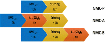
The coating is applied to the material remaining in the CSTR by pumping 2 M of aluminium sulfate hydrate (Al2(SO4)3·H2O, 98%, Sigma Aldrich) for 1 h. As shown in Fig. 1, two ways of adding Al precursor were performed. The sample NMC-P stands for the pristine sample, which follows the preparation procedure described previously. The sample NMC-A represents the synthesis where aluminium precursor is pumped just before the 12 h-stirring. The sample NMC-B represents the synthesis where aluminium sulfate is pumped right after the 12 h-stirring.
Following the synthesis, the precursors are washed with DI water, filtered, and dried under vacuum at 80 °C. They are then mixed with ground lithium hydroxide monohydrate (LiOH·H2O, 98%, Strem Chem). LiOH was added in excess, with a molar ratio of (1![[thin space (1/6-em)]](https://www.rsc.org/images/entities/char_2009.gif) :
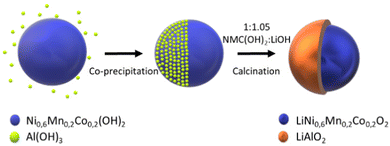
:![[thin space (1/6-em)]](https://www.rsc.org/images/entities/char_2009.gif) 1.05), to ensure the lithiation of NMC as well as the coating precursors. The mixture is then annealed in air at 450 °C and 850 °C for 4 h and 12 h, respectively, as schematised in Fig. 2.
1.05), to ensure the lithiation of NMC as well as the coating precursors. The mixture is then annealed in air at 450 °C and 850 °C for 4 h and 12 h, respectively, as schematised in Fig. 2.
2.2. Characterisation techniques
Powder X-Ray diffraction (XRD) was carried out in a PanAlytical Empyrean 3 equipped with a Cu target X-Ray tube, CuKα, λ = 1.54178 Å operated at 45 kV and 40 mA. Diffraction patterns were collected in the scattering angle (2θ) range of 10–80 at 0.0131° step size for 1 h measurement. XRD patterns were collected and sequentially Rietveld-refined by HighScore v.4.9.A Hitachi Tabletop microscope TM3030 Plus scanning electron microscope (SEM) and a Thermo Scientific Quattro environmental scanning electron microscope (ESEM) in high vacuum mode (10–15 kV) were used to study the morphology of precursors and sintered samples. The SEM is equipped with a Bruker QUANTAX EDS for SEM energy-dispersive X-Ray spectrometer (EDX) that was used to confirm the composition of the coating.
A VG Escalab 220i XL X-Ray Photoelectron Spectroscopy (XPS) was used to study the chemical bonds and the electronic structure of the surface coating. The X-ray source used was an achromatic Al Kα radiation (1486.6 eV), under a pressure of 1 to 3 × 10⁻⁹ mbar. Survey spectra were recorded with a pass energy of 100 eV and, for high-resolution spectra, a pass energy of 20 eV was used. For the deconvolution of the spectra, the Thermo Avantage software was used.
A 4210 MP-AES Agilent Microwave Plasma Atomic Emission Spectrometer was used to quantify elements of interest: Al, Ni, Mn, Co, and Li. The samples were digested in an aqua regia solution at 80 °C for 1 h. As shown in Table 1, two wavelengths were used for the detection of each of the elements, with 5 read replicates per wavelength.
| Al | Ni | Mn | Co | |
|---|---|---|---|---|
| λ 1 (nm) | 394.401 | 310.155 | 279.482 | 340.512 |
| λ 2 (nm) | 396.152 | 361.939 | 403.076 | 350.631 |
27Al Magic Angle Spinning Nuclear Magnetic Resonance Spectroscopy (27Al MAS NMR) Experiments were performed at a field of 9.4 T, Larmor frequency of 104 MHz, and a rotor-synchronised echo pulse sequence with a pulse width of 3.6 μs. Diamagnetic species were determined at a pulse delay of 10 s while paramagnetic species were identified with 0.0002 s. A spinning speed of 5 kHz was used at 298 K with a 4 mm probe.
Electrochemical measurements were carried out via galvanostatic charge/discharge cycling using standard CR2032 coin cells with lithium metal (99.9%, Alfa Aesar) as the anode. Electrodes were formulated with a ratio of 90 wt% Active Material to 5 wt% super C-65 conductive carbon black (TIMCAL) to 5 wt% PVDF binder (polyvinylidene fluoride, Sigma Alrich) with NMP (1-methyl-2-pyrrolidone, Sigma Aldrich) as the solvent. The cathodes were made by casting the slurries on aluminium foil and drying them in a vacuum oven at 120 °C overnight. The loading of the cathodes was about 4.3 mg cm−2. The electrolyte contained 1 M LiPF6 dissolved in ethylene carbonate: ethyl methyl carbonate (3EC:7EMC), with 5% v/v of vinylene carbonate (VC), purchased from Sigma Aldrich. The coin cells were assembled in an argon-filled glove box, with lithium foil as the counter electrode and a Celgard separator. The cells were cycled at two different voltage ranges (3.0–4.2 V and 3.0–4.4 V vs. Li/Li+) at the desired C rate (1C = 160 mA g−1), at room temperature and at high temperature (25 and 45 °C) with an Arbin BT2000 Cycler. For the rate performance tests, the cells were charged and discharged at a voltage range of 3.0–4.2 V vs. Li+/Li with current densities ranging from 0.1 to 10C. Electrochemical impedance spectroscopy (EIS) measurements were performed on VMP potentiostat with a frequency range of 200 kHz to 100 mHz with an AC voltage of 10 mV amplitude. EIS measurements were taken at room temperature on cells that were fully discharged. The setup was composed of three electrodes, using NMC as the working electrode and Li as the reference and the counter electrodes.
3. Results and discussion
The XRD diagrams of pristine and coated NMC-A and NMC-B powders are presented in Fig. 3(a). The structures found for all samples are in good agreement with the hexagonal α-NaFeO2 layered structure, belonging to the R![[3 with combining macron]](https://www.rsc.org/images/entities/char_0033_0304.gif) m space group.
m space group.
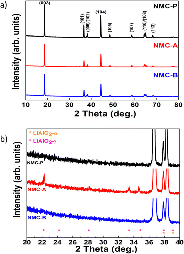 | ||
| Fig. 3 XRD patterns of NMC-P, NMC-A and NMC-B (a), and the zoom plot of the region showing the main LiAlO2 peaks (b). | ||
The NMC peaks are present in all three XRD spectra. In addition, coated samples exhibited new diffraction peaks corresponding to the LiAlO2 structure, Fig. 3(b).
Sample NMC-A shows the presence of two LiAlO2 phases (α-LiAlO2 and γ-LiAlO2), while only the α-LiAlO2 phase is found in NMC-B.
The distinct splitting of the (006)/(102) and (108)/(110) doublets of all samples indicate good crystallinity and a well developed layered structure.25 To investigate the structural properties of the different samples, Rietveld refinement was performed in this regard, and the results are reported in Table 2. The parameters c/3a and the I003/I104 ratios of coated samples are all larger than 1.6333 and 1.2, respectively. This indicates that the structures are well ordered, and the cation mixing between Li+ and Ni2+ is almost negligible.29
| NMC-P | NMC-A | NMC-B | |
|---|---|---|---|
| a (Å) | 2.8719(6) | 2.8674(7) | 2.8670(1) |
| c (Å) | 14.2354(4) | 14.2362(4) | 14.2377(7) |
| c/3a | 1.6522 | 1.6549 | 1.6554 |
| I (003)/I(104) | 1.07 | 1.23 | 1.31 |
| V (Å3) | 101.7 | 101.4 | 101.3 |
| R | 0.475 | 0.479 | 0.434 |
| T TM | 2.159 | 2.19 | 2.154 |
| T Li | 2.586 | 2.555 | 2.592 |
| R (expected)/% | 9.7763 | 7.1949 | 7.3662 |
| R (profile)/% | 7.9338 | 7.1602 | 6.8918 |
| R (weighted profile)/% | 10.6542 | 9.4677 | 9.1462 |
| GOF | 1.0898 | 1.3159 | 1.2416 |
| d-Statistic | 0.4908 | 0.4057 | 0.2891 |
| Occupancy factor | |||
| Li | 0.938 | 0.924 | 0.928 |
| Ni | 0.636 | 0.636 | 0.56 |
| Mn | 0.21 | 0.21 | 0.239 |
| Co | 0.214 | 0.21 | 0.238 |
| Al | 0 | 0 | 0.021 |
The other indicator generally used to confirm the hexagonal structure is the R factor (R = (I006 + I102)/I101). The lower the R factor, the better the hexagonal ordering, and it would suggest better electrochemical performance.30
As shown in Table 2, sample NMC-B has a lower R, which stipulates better hexagonal ordering of its lattice than that of NMC-A, which in turn is better than that of NMC-P.
The cell parameters show that a decreases by 0.15% and 0.17% in NMC-A and NMC-B respectively compared to that of the pristine sample. On the contrary, c increases by 0.0056% and 0.016% in NMC-A and NMC-B respectively compared to the reference sample.
As mentioned previously, NMC-A displays the presence of two phases of LiAlO2.
These two phases have been quantified, and the results obtained after refinement are 7.8% of α-LiAlO2 and 2.2% of γ-LiAlO2. While only the α-LiAlO2 is found at 1.8% in NMC-B. The formation of this coating requires the consumption of lithium from the NMC lattice, referred to as lithium loss. Hence, lithium loss is slightly more pronounced in NMC-A than in NMC-B. This is confirmed, notably in Table 2, by the occupancy factor of lithium which is lower in NMC-A compared to that of NMC-B. To shed light on the obtained lattice parameters, we will use the concept of charge compensation as well as the radii of the ions in the lattice.31–33 Thereby, the decrease in lattice parameter a can be explained by the oxidation of Ni2+ (0.69 Å) to Ni3+ (0.56 Å). This oxidation may be due to a charge transfer that can be induced by the charged Al3+ of the LiAlO2 coating. Another possible explanation is the non-faradaic migration of Li+ from NMC lattice to the LiAlO2 coating.34 Meanwhile, the TM slabs become positively charged and repel each other along the c-axis causing the lattice parameter c to increase, justifying the variation in cell parameters.35
To better comprehend these variations, another variable must be considered, namely the possibility of substitution of TM ions by Al3+ ions in the TM slab.
The Rietveld refinement of the diffracted patterns was carried out considering the possible occupancy of Al3+ in the TM planes of the lattice structure of NMC. It is known that dopant ions would be inserted on sites that minimise the cost in Coulombic energy, meaning that Al3+ can substitute trivalent ions. It is therefore possible that Al3+ substitutes Ni3+ and Co3+. Also, since the ionic radii of Ni3+ (0.56 Å), Co3+ (0.545 Å), and Mn4+ (0.54 Å) are close to that of Al3+ (0.53 Å), substitution may occur.36,37 Due to a large difference in ionic radii between Al3+ (0.53 Å), Li+ (0.76 Å, 3a) and Ni2+ (0.69 Å), the substitution in these cases cannot occur. Refinement of the occupancy factor also confirms this hypothesis since the occupation of Co, Mn, and Ni is reduced, which means that they have been substituted by another element, in this case Al3+. As the radius of the latter is the smallest among the elements it can substitute, its introduction into the lattice structure induces a small shrinking in the cell volume of NMC.
Essentially, the variation observed in the cell parameter of NMC-A could be explained by a loss of lithium for the formation of two phases of LiAlO2. Regarding the NMC-B sample, the variation is slightly more pronounced due to both lithium loss for the formation of the α-LiAlO2 phase and the Al3+ diffusion.
Additional information was extracted from the Rietveld refinement such as the thickness of the TM-O2 planes (TTM) and the inter-slab space (TLi). In the case of NMC-A, the TTM increased, whereas the TLi decreased compared to that of NMC- P. In contrast, in NMC-B, the TTM decreased, whereas TLi increased compared to that of NMC-P. It has been reported that an increased TLi could enable Li+ intercalation/deintercalation kinetics.37 This property is obviously beneficial for the electrochemical behaviour observed in NMC-B, leading to expected better performances in NMC-B compared to NMC-A and NMC-P.
The morphology of the coated and uncoated samples was investigated via SEM. As shown in Fig. 4, the synthetized samples present a homogeneous particles’ morphology for each material. Moreover, the appearances of all three NMC samples are similar, and they exhibit spherical secondary particles that are 10–14 μm in diameter, which is the standard particle size found in literature.38
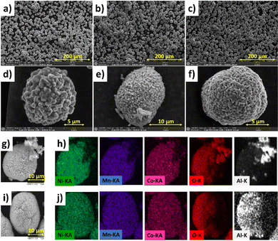 | ||
| Fig. 4 SEM micrographs of NMC-P (a and d), NMC-A (b and e) and NMC-B (c and f) at 10 kV. SEM/EDX mapping of NMC-A (g and h) and NMC-B (i and j). | ||
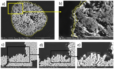
Correspondingly, Fig. 4(g and h) shows the EDX mapping of a single particle for both coated samples presenting the elemental distribution. The elements Ni, Mn, Co, and O are uniformly distributed all over the particles. In both cases, the presence of aluminium on the surface is evidenced. The cross-section of NMC-B, Fig. 5 demonstrates the coating layer on secondary particles. The coating is distinguishable from the NMC particle by the difference in chemical contrast observed using a backscattered electron detector. The coating is probably inhomogeneous in thickness (20–150 nm), but is well distributed across the NMC secondary particle surface.
However, NMC-A shows the presence of Al agglomerates on the surface, unlike the NMC-B sample which presents a homogeneous distribution of Al over the entirety of the surface.
Aluminium sulfate was pumped into the reaction mixture during a period of one hour in both cases, meaning that we expected to find the same percentage of aluminium in both samples. However, the amount of aluminium found in the two samples varied. Table 3 represents the concentrations of the elements of interest in all three samples analysed by MP-AES. The concentrations of Ni, Mn and Co agree with the desired composition of NMC622. However, the amount of Al found in NMC-A is higher than that of NMC-B.
| Al (mol) | Ni (mol) | Mn (mol) | Co (mol) | x (mol) LiAlO2 | y (mol) Li(NMC)O2 | |
|---|---|---|---|---|---|---|
| NMC-P | 0.00 | 0.61 | 0.21 | 0.21 | 0.00 | 1.00 |
| NMC-A | 0.13 | 0.60 | 0.20 | 0.20 | 0.13 | 0.87 |
| NMC-B | 0.05 | 0.56 | 0.24 | 0.24 | 0.05 | 0.95 |
The method used for the preparation of the NMC-A sample initiates a complex mechanism of precipitation/dissolution of aluminium on the surface of the particles. The pH of the solution, being very high (pH 11), induces dissolution of aluminium sulfate in the CSTR.39 In parallel, continuous stirring for a period of 12 hours causes precipitation of aluminium hydroxide nanoparticles on the germination sites formed at the surface of NMC particles.39,40 In addition to forming a thin coating layer, aluminium hydroxide also heterogeneously agglomerates on the surface of NMC-A particles as shown in Fig. 4.
In contrast, the NMC-B method yields smoother particle surface due to increased collisions during the stirring period, after which, the dissolved aluminium precipitates on the germination sites of secondary particles’ surface. Firstly, the Al(OH)3 precipitates by filling the pores between the primary particles, then by precipitating on the surface of primary particles, it covers the entirety of the secondary particles homogeneously. The precursor thus synthesised is recovered directly after the injection of aluminium, which prevents agglomeration. Then, by reacting Al(OH)3 with LiOH during the precursor heat treatment, the produced LiAlO2 forms a crystalline dense layer.41
XPS surface analysis was conducted to study the electronic state of Al in the coating on the synthesised cathode material.
The survey spectrum of NMC-P shown in Fig. 6(a) displays the main electronic state of d-ions in the surface layer of particles corresponding to Ni, Co, Mn, and O. No impurity other than the carbon used for XPS spectrum calibration (284.6 eV) was detected. The survey spectrum of coated NMC displayed peaks ascribed to Al 2p, which proves the presence of Al species on the surface of NMC-A and NMC-B. A detailed spectrum in the region between 80 and 65 eV is shown in Fig. 6(d, e and f). Further deconvolution reveals that this region includes the Al 2p core levels and the Ni 3p peaks. The contribution of the peak's Ni 3p was fit into 2 components, one at binding energy of 67.48 eV (Ni 3p3/2) and the other at 71.58 eV (Ni 3p1/2).
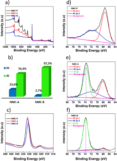 | ||
| Fig. 6 XPS Survey spectra (a). Contribution of Ni and Al found on the surface of coated samples (b). O 1s spectra (c). Ni 3p and Al 2p XPS spectra of NMC-P (d), NMC-A (e) and NMC-B (f). | ||
Coated samples indicate the presence of Al3+ at 73.7 eV and 73.8 eV for NMC-A and NMC-B respectively.42,43 The area under the deconvoluted curves was used to quantify the coating on the particle's surface by comparing signals of Nickel versus that of Aluminium, Fig. 6(b). Nickel was found in lower concentration on the surface of NMC-B, indicating that the surface has been well coated. Also, according to the survey spectra, the relative intensity of O 1s peak, Fig. 6(c), at around 530 eV was higher for the coated samples. This supports the claim that the LiAlO2 coating layer is present on the particles’ surface.44
To get deeper insight into the chemical structure of the coating and the possible aluminium insertion from the surface to the bulk, 27Al MAS NMR spectroscopy measurements were performed.
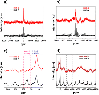
The first analysis was conducted to study the diamagnetic Aluminium species at the particle surface by using a delay time of 10 s, as shown in Fig. 7(a and c). According to Han et al., 4-coordinate 27Al peaks at ∼69 ppm represent the formation of γ-LiAlO2, and 6-coordinate 27Al peaks at ∼15 ppm can be assigned to the presence of α-LiAlO2.45 Both coated samples NMC-A and NMC-B show the presence of a broad and distorted peak at ∼15 ppm which can be assigned to the presence of α-LiAlO2 coating. Nevertheless, only NMC-A showed a peak at ∼69 ppm which can be attributed to the formation of γ-LiAlO2. These results corroborate the XRD analyses discussed further.
Additionally, the study of the paramagnetic species on the Al3+ was performed to evaluate the possibility of Al diffusion from the surface to the lattice core, Fig. 7(b). The signature of Al3+ diffusion into the bulk is detected at −200, −400, −600 and −1000 ppm which correspond to a lattice composed of Al–1Ni–5Co, Al–2Ni–4Co, Al–3Ni–3Co and Al–5Ni–1Co respectively.46
Fig. 7(d) shows that there is no peak related to the diffusion of Al3+ into the lattice of NMC-A, or that it is below the limit of detection.
Nevertheless, the NMC-B spectrum shows broad peaks centered around −600 ppm, revealing the presence of an Al lattice within the transition metal layers.
This is due to the insertion of Al3+ from the coating surface into the core of the NMC particle during high temperature annealing.
Electrochemical testing of all samples is carried out to elucidate the influence of the coating on the cyclability. Long-term cycling experiment was carried out at 3.0–4.2 V vs. Li+/Li at room temperature, Fig. 8(a).
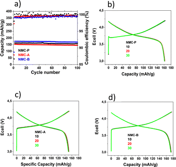 | ||
| Fig. 8 Electrochemical performances of various samples at room temperature from 3.0 V to 4.2 V vs. Li+/Li (a). Charge/discharge curves for NMC-P (b), NMC-A (c) and NMC-B (d). | ||
The cells were initially cycled at C/20 for one cycle. Thereafter, the long-term cycling stability was evaluated at C/5 in the same potential range.
Fig. 8(b, c and d) shows the galvanostatic charge/discharge profiles of pristine, NMC-A and NMC-B materials after the 10th, 20th and 30th cycle. All three electrodes display similar curves, with a typical plateau at 3.75 V, which indicate that LiAlO2 coating layer does not affect the electrochemical behaviour of NMC.
Pristine NMC shows initial discharge specific capacity of 162.4 mA h g−1 and the corresponding coulombic efficiency is 99.5%. While the initial discharge capacity of NMC-A and NMC-B are 152.4 mA h g−1 (99.4%), and 174.6 mA h g−1 (99.2%) respectively, the coated NMC-B sample shows a higher initial discharge capacity when compared to the pristine sample. This may be the result of the Al3+ diffusion observed for the NMC-B sample, which increased the thickness of the inter-slab space, TLi, and allowed a higher delivered specific capacity. NMC-A electrode shows a lower specific capacity when compared to the pristine sample. This may be the result of the dense agglomerate particles of the coating, which isolate some of the primary particles. This also explains the lower capacity for NMC-A in comparison with NMC-P.
Increasing temperature and cut-off voltage during cycling accelerate undesirable side reactions that occur at the NMC interface. Under these conditions, on one hand, transition metals in the positive electrode can be oxidized and dissolve into the electrolyte. On the other hand, the electrolyte can be oxidized at the positive electrode causing the depletion of the electrolyte's lithium-ion inventory. In both cases, the electrochemical performance of the cell is affected by the loss of its capacity.47 In order to evaluate the effect of LiAlO2 coating on NMC electrodes, cells were cycled under these conditions.
To evaluate the thermal stability of the different cathodes, long-term cycling was carried out at a higher temperature of 45 °C, at 3.0–4.2 V vs. Li+/Li, as shown in Fig. 9(a).
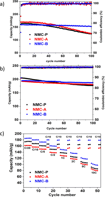 | ||
| Fig. 9 Electrochemical performance at high temperature 45 °C from 3.0 V to 4.2 V vs. Li+/Li (a), at room temperature and high potential window from 3.0 to 4.4 V vs. Li+/Li (b). Rate capability (c). | ||
High temperature cycling shows very clearly the fading capacity of the pristine sample due to the acceleration of undesirable side reactions and demonstrates the need to improve the thermal stability of NMC. Among the two coated samples, NMC-B shows the best cycling properties with great cell polarisation.
The capacity retention obtained by the NMC-B (96.3%) is higher than that of the NMC-A (70.1%) and the pristine (70.2%) samples. The crucial role of the LiAlO2 coating layer is highlighted by the better capacity retention exhibited by NMC-B. In fact, it may be due to the prevention of side reactions between the cathode material surface and the electrolyte. On the other hand, we hypothesized that the high-capacity retention may be explained by the mechanical toughness of the well-coated secondary particles, which improves the cycling performance. Using a chemical approach, the structural stability between the layers may have been improved by the presence of an Al–O bond bringing a higher energy to the Metal–Oxygen bonds.48 When compared to the performance of NMC-P, NMC-A shows a slight loss in capacity retention demonstrating the importance of a uniform coating.
Fig. 9(b) shows a cycling experiment at a higher potential window, 3.0–4.4 V vs. Li+/Li at room temperature. Both coated samples showed a better capacity retention. The calculated capacity retention after 100 cycles equals 86.4% for NMC-P, 93.5% for NMC-A and 96.4% for NMC-B. These results are mainly due to the protection of the cathode surface and demonstrate the important role of the LiAlO2 coating layer, which consists in stabilising the interface structure when charged to higher cut-off voltage.
Fig. 9(c) shows a comparison of the rate capability plot of all electrodes from 0.1 to 10C in the voltage window of 3.0 to 4.2 V versus Li+/Li. The NMC-B coated material shows a higher specific capacity than the pristine and the NMC-A electrodes for each discharge rate. Moreover, the NMC-B electrode showed faster discharge performance than the pristine electrode. Indeed, according to the initial capacity delivered at 0.05C discharge rate, NMC-P delivers capacities equal to 97, 93, 86, 80, 73, 63 and 52% at 0.1, 0.25, 0.5, 1, 2, 5, and 10C discharge rate, respectively. Meanwhile, NMC-B electrode delivers capacities equal to 97, 94, 87, 81, 75, 66 and 56% at corresponding discharge current densities, respectively. This demonstrates that the coating on the NMC-B affects the kinetic positively by providing a much more stable interface for charge transfer. This could be attributed to the improved Li+ ion conductivity due to the presence of Li ion sites inside the coating layer thus allowing the Li+ intercalation/de-intercalation. Nonetheless, the coating method used on NMC-A showed lower specific capacities than the pristine electrode for each discharge rate. However, the NMC-A electrode showed a slight improvement in discharge performance compared to the pristine electrode. Indeed, according to the initial capacity delivered at 0.05 discharge rate, NMC-A delivers capacities equal to 97, 93, 86, 80, 74, 64 and 53% at corresponding discharge current densities, respectively. This may have stemmed from the agglomerates of LiAlO2 found on the surface of the particles.
Since the cells were programmed to go back to C/10 rate after each test, the results showed that full capacities were recovered for all 3 cells, indicating their excellent rate performance and a great restorability.
To better understand the effect of LiAlO2 coating on NMC, electrochemical impedance spectroscopy (EIS) was performed. As shown in Fig. 10.
The first impedance measurements were taken after 5 hours of OCV, before cycling. The second impedance measurement was taken after 2 hours of OCV, after 100 cycles. The cells were compared at the same fully discharged state, before and after 100 cycles. The setup was composed of three electrodes, using NMC as the working electrode and Li as the reference and the counter electrodes.
Fig. 10(a and b) shows the Nyquist plot of all three electrodes before and after cycling. All spectra show two distinct semicircles attributed to the cathode electrolyte interphase resistance (CEI), and the charge-transfer resistance.
The equivalent circuit used is composed of four resistance components: ohmic resistance of liquid electrolyte (RS), high-mid frequency related to the interfacial resistance from the CEI layer (RCEI), a mid-low frequency charge-transfer resistance which represents Li-ion migration at the surface of material (RCT) and a low-frequency mass transfer resistance (W). The RCEI and RCT resistance values according to the fitting results from the equivalent circuits are shown in a column graph in Fig. 10(c and d).
The values obtained for Rs resistance are almost similar, before and after cycling for all three electrodes. This is reasonable since the same electrolyte was used in all cells.
The RCEI of the pristine electrode before cycling is 5.45 Ohm and it increases to 9.03 Ohm after 100 cycles. This increase can be interpreted as the oxidative decomposition of the electrolyte and the formation of the ion conductive CEI layer. In contrast, the RCEI values for both coated electrodes decrease from 23.85 and 86.75 Ohm before cycling to 17.24 and 12.05 Ohm after cycling, for NMC-A and NMC-B respectively. These values are relatively higher than those obtained with the pristine electrode due to the presence of a coating layer on their surface and the activation of the material. However, the RCEI increased with the pristine electrode and decreased with both coated electrodes, after cycling. This may be related to a decrease of the oxidative decomposition of the electrolyte, less passivation of the NMC surface and therefore better surface protection by the LiAlO2 coating.
On the other hand, the decrease of RCEI is more considerable in NMC-B compared to that of NMC-A. Before cycling, NMC-B shows a higher RCEI than NMC- A due to higher thickness of its coating layer. After cycling, NMC-B shows a lower RCEI than NMC-A due to better protection of the interface while forming a more stable and conductive CEI layer.
The same trend was observed with the charge transfer resistance, RCT. The RCT of the pristine electrode before cycling is 26.81 Ohm and it increases to 98.66 Ohm after 100 cycles. This could be interpreted as the formation of the CEI layer, as confirmed by the RCEI obtained. In contrast, the RCT values for both coated electrodes decrease from 12.36 and 15.99 Ohm before cycling to 10.31 and 5.51 Ohm after cycling, for NMC-A and NMC-B respectively. The lower charge-transfer resistance of both LiAlO2 coated samples, compared to NMC-P, after cycling, shows that the coating enhances the charge-transfer kinetics upon prolonged cycling. The NMC-B electrode shows better results for RCEI and RCT over the cycle life of the electrode, demonstrating the effectiveness of the method used to perform the LiAlO2 coating on NMC. However, the chemistry, morphology and growth mechanism intricacies of the CEI formation are still far from being completely understood. Thus, to have a better fundamental understanding of the effect of the LiAlO2 coating layer and Al3+ ions on the CEI formation, it is important to devote a complete separate study to it in the future.
To summarize, the method used for the synthesis of NMC-A sample, where the aluminium sulfate solution is pumped before the stirring period of 12 hours, causes the formation of an uncontrollable excess of LiAlO2 on the surface of the NMC. It appears that such excess can harm the electrochemical performance of the batteries. This effect was noted more particularly during long-term cycling at high temperature.
The method used for the synthesis of the coated NMC-B material, where the aluminium sulfate solution is pumped right after the stirring period of 12 hours, gives better electrochemical results reflected by greater specific and retention capacities at higher potential window and higher temperature.
4. Conclusions
One-pot LiAlO2-coated Li[Ni0.6Mn0.2Co0.2]O2 material with excellent cycling performance was successfully synthetized. In this study, two synthesis methods have been investigated to determine the one that allows better electrochemical properties of the cathode material.The NMC-A sample was synthetized following the same process as that adopted for the pristine sample, adding a step of pumping an aluminium sulfate solution into the CSTR before the stirring period of 12 hours. This method causes the formation of an excess of LiAlO2 agglomerates on the surface, and this can harm the electrochemical cycling of the battery.
The NMC-B sample was synthetized following the same process as that adopted for the pristine sample, adding a step of pumping an aluminium sulfate solution into the CSTR right after the stirring period of 12 hours. The best method allowing the synthesis of a homogeneous LiAlO2 coating layer on NMC622 is that used for the NMC-B sample.
Various techniques were used to study the surface and structural modification of NMC622 by the LiAlO2 coating layer. EDX, XPS, and 27Al MAS NMR results confirmed the presence of a coating layer on the surface of the particles on both coated samples. XRD results confirmed the maintenance of the structural integrity of the NMC. A slight Al+3 diffusion from the surface coating to the lattice core of NMC-B was observed using 27Al MAS NMR and this led to a positive effect on the cycling properties.
Coating improved the material's long-term cycling performance at high temperature (45 °C) and at high cut-off voltage (3.0–4.4 V vs. Li+/Li) reflected by both better specific and retention capacities. EIS confirmed that LiAlO2 coating layer prevents side reactions, resulting in reduced cathode electrolyte interface formation and charge-transfer resistance during cycling.
LiAlO2 coating layer enables the formation of a physical barrier between the cathode active material and the electrolyte. This acts as an efficient protection against the electrolyte decomposition and the degradation of the oxide structure.
This one-pot synthesis method is a useful methodology to adopt not only for modification of the cathode surface, but also as a simple and cost-effective way for large-scale production.
Considering the excellent results obtained with our one pot coating on NMC particles, this method can be simply transposed to other types of coatings for cathode materials using a CSTR.
Author contributions
Ouardia Touag: conceptualisation, data curation, formal analysis, investigation, methodology, software, writing – review & editing, writing – original draft. Gaël Coquil: investigation, methodology, software. Mathieu Charbonneau: investigation, methodology, software. Gabrielle Foran: software. Amrita Ghosh: software. Denis Mankovsky: investigation, software, writing – review & editing. Mickaël Dollé: visualisation, supervision, project administration, funding acquisition, writing – review & editing.Conflicts of interest
There are no conflicts to declare.Acknowledgements
For this study, the authors gratefully acknowledge the financial support provided by a grant from the National Sciences and Engineering Research Council of Canada (NSERC-RDCPJ 537262-18) and from Ministère de l’Économie, de l'Innovation et de l'Énergie, through the organization InnovÉÉ. We are also grateful to Steeve Rousselot from Université de Montréal for his knowledges and help regarding the impedance measurements. We acknowledge Thierry Marris and Daniel Chartrand from Université de Montréal for the help with the XRD measurements. We acknowledge Christophe Chabanier from Institut National de la Recherche Scientifique (INRS) for the help with the XPS measurements.Notes and references
- M. Dixit, et al., Origin of Structural Degradation During Cycling and Low Thermal Stability of Ni-Rich Layered Transition Metal-Based Electrode Materials, J. Phys. Chem. C, 2017, 121(41), 22628–22636 CrossRef CAS.
- A. Chakraborty, et al., Layered Cathode Materials for Lithium-Ion Batteries: Review of Computational Studies on LiNi1–x–yCoxMnyO2 and LiNi1–x–yCoxAlyO2, Chem. Mater., 2020, 32(3), 915–952 CrossRef CAS.
- Q. Wang, et al., Green technology innovation development in China in 1990–2015, Sci. Total Environ., 2019, 696, 134008 CrossRef CAS PubMed.
- C. Banza Lubaba Nkulu, et al., Sustainability of artisanal mining of cobalt in DR Congo, Nat. Sustainable, 2018, 1(9), 495–504 CrossRef PubMed.
- A. L. Lipson, et al., Stabilizing NMC 811 Li-Ion Battery Cathode through a Rapid Coprecipitation Process, ACS Appl. Energy Mater., 2021, 4(2), 1972–1977 CrossRef CAS.
- T. Li, et al., Degradation Mechanisms and Mitigation Strategies of Nickel-Rich NMC-Based Lithium-Ion Batteries, Electrochem. Energy Rev., 2020, 3(1), 43–80 CrossRef.
- G. Sun, et al., The effect of cation mixing controlled by thermal treatment duration on the electrochemical stability of lithium transition-metal oxides, Phys. Chem. Chem. Phys., 2017, 19(44), 29886–29894 RSC.
- A. L. Lipson, et al., Improving the Thermal Stability of NMC 622 Li-Ion Battery Cathodes through Doping During Coprecipitation, ACS Appl. Mater. Interfaces, 2020, 12(16), 18512–18518 CrossRef CAS PubMed.
- P. Hou, et al., Core–shell and concentration-gradient cathodes prepared via co-precipitation reaction for advanced lithium-ion batteries, J. Mater. Chem. A, 2017, 5(9), 4254–4279 RSC.
- J. Ahn, et al., Ultrathin ZrO2 on LiNi0.5Mn0.3Co0.2O2 electrode surface via atomic layer deposition for high-voltage operation in lithium-ion batteries, Appl. Surf. Sci., 2019, 484, 701–709 CrossRef CAS.
- J.-Z. Kong, et al., Ultrathin ZnO coating for improved electrochemical performance of LiNi0.5Co0.2Mn0.3O2 cathode material, J. Power Sources, 2014, 266, 433–439 CrossRef CAS.
- M. J. Herzog, D. Esken and J. Janek, Improved Cycling Performance of High-Nickel NMC by Dry Powder Coating with Nanostructured Fumed Al2O3, TiO2, and ZrO2: A Comparison, Batteries Supercaps, 2021, 4(6), 1003–1017 CrossRef CAS.
- J. Cho, Y. J. Kim and B. Park, Novel LiCoO2 Cathode Material with Al2O3 Coating for a Li Ion Cell, Chem. Mater., 2000, 12(12), 3788–3791 CrossRef CAS.
- K.-L. Chiu, Recovery of Valuable Metals from Spent Lithium Ion Batteries (LIBs) Using Physical Pretreatment and a Hydrometallurgy Process, Adv. Mater., 2019, 8(1), 12 CrossRef CAS.
- X. Xiong, et al., A modified LiF coating process to enhance the electrochemical performance characteristics of LiNi0.8Co0.1Mn0.1O2 cathode materials, Mater. Lett., 2013, 110, 4–9 CrossRef CAS.
- J. Xie, et al., Atomic Layer Deposition of Stable LiAlF4 Lithium Ion Conductive Interfacial Layer for Stable Cathode Cycling, ACS Nano, 2017, 11(7), 7019–7027 CrossRef CAS PubMed.
- H. B. Kim, et al., Electrochemical and thermal characterization of AlF3-coated Li[Ni0.8Co0.15Al0.05]O2 cathode in lithium-ion cells, J. Power Sources, 2008, 179(1), 347–350 CrossRef CAS.
- W. Li, et al., Ultra-Thin AlPO4 Layer Coated LiNi0.7Co0.15Mn0.15O2 Cathodes With Enhanced High-Voltage and High-Temperature Performance for Lithium-Ion Half/Full Batteries, Front. Chem., 2020, 8, 597 CrossRef CAS PubMed.
- G. Li, Z. Yang and W. Yang, Effect of FePO4 coating on electrochemical and safety performance of LiCoO2 as cathode material for Li-ion batteries, J. Power Sources, 2008, 183(2), 741–748 CrossRef CAS.
- P. Zou, et al., Facile and efficient fabrication of Li3PO4-coated Ni-rich cathode for high-performance lithium-ion battery, Appl. Surf. Sci., 2020, 504, 144506 CrossRef CAS.
- S.-J. Sim, et al., Use of carbon coating on LiNi0.8Co0.1Mn0.1O2 cathode material for enhanced performances of lithium-ion batteries, Sci. Rep., 2020, 10(1), 11114 CrossRef CAS PubMed.
- Y. Cao, et al., Conductive Polymers Encapsulation To Enhance Electrochemical Performance of Ni-Rich Cathode Materials for Li-Ion Batteries, ACS Appl. Mater. Interfaces, 2018, 10(21), 18270–18280 CrossRef CAS PubMed.
- L. Li, Z. Chen, Q. Zhang, M. Xu, X. Zhou, H. Zhu and K. A. Zhang, A hydrolysis-hydrothermal route for the synthesis of ultrathin LiAlO2-inlaid LiNi0.5Co0.2Mn0.3O2 as a high-performance cathode material for lithium ion batteries, J. Mater. Chem. A, 2015, 3(2), 894–904 RSC.
- C. Chen, et al., Tunable LiAlO2/Al2O3 Coating through a Wet-Chemical Method To Improve Cycle Stability of Nano-LiCoO2, ACS Appl. Energy Mater., 2019, 2(5), 3098–3113 CrossRef CAS.
- W. Liu, et al., Significantly improving cycling performance of cathodes in lithium ion batteries: The effect of Al2O3 and LiAlO2 coatings on LiNi0.6Co0.2Mn0.2O2, Nano Energy, 2018, 44, 111–120 CrossRef CAS.
- J. S. Park, et al., Ultrathin Lithium-Ion Conducting Coatings for Increased Interfacial Stability in High Voltage Lithium-Ion Batteries, Chem. Mater., 2014, 26(10), 3128–3134 CrossRef CAS.
- M. J. Herzog, et al., Increased Performance Improvement of Lithium-Ion Batteries by Dry Powder Coating of High-Nickel NMC with Nanostructured Fumed Ternary Lithium Metal Oxides, ACS Appl. Energy Mater., 2021, 4(9), 8832–8848 CrossRef CAS.
- A. V. Bommel and J. R. Dahn, Analysis of the Growth Mechanism of Coprecipitated Spherical and Dense Nickel, Manganese, and Cobalt-Containing Hydroxides in the Presence of Aqueous Ammonia, Chem. Mater., 2009, 21, 1500–1503 CrossRef.
- Y. Wei, et al., Enhanced electrochemical performance and safety of LiNi0.8Co0.15Al0.05O2 by LiFePO4 modification, Chem. Phys. Lett., 2020, 751, 137480 CrossRef CAS.
- L. Li, et al., Co-modification by LiAlO2-coating and Al-doping for LiNi0.5Co0.2Mn0.3O2 as a high-performance cathode material for lithium-ion batteries with a high cutoff voltage, J. Alloys Compd., 2018, 768, 582–590 CrossRef CAS.
- R. D. Shannon and C. T. Prewitt, Revised values of effective ionic radii, Acta Crystallogr., Sect. B: Struct. Crystallogr. Cryst. Chem., 1970, 26(7), 1046–1048 CrossRef CAS.
- W. Zhao, L. Zou, H. Jia, J. Zheng, D. Wang, J. Song, C. Hong, R. Liu, W. Xu, Y. Yang and J. Xiao, Optimized Al Doping Improves Both Interphase Stability and Bulk Structural Integrity of Ni-Rich NMC Cathode Materials, ACS Appl. Energy Mater., 2020, 3(4), 3369–3377 CrossRef CAS.
- A. Dianat, N. Seriani, M. Bobeth and G. Cuniberti, Effects of Al-doping on the properties of Li–Mn–Ni–O cathode materials for Li-ion batteries: an ab initio study, J. Mater. Chem. A, 2013, 1(32), 9273–9280 RSC.
- J. L. White, et al., Nickel and Cobalt Oxidation State Evolution at Ni-Rich NMC Cathode Surfaces during Treatment, J. Phys. Chem. C, 2020, 124(30), 16508–16514 CrossRef CAS.
- X.-L. Wang, et al., Visualizing the chemistry and structure dynamics in lithium-ion batteries by in-situ neutron diffraction, Sci. Rep., 2012, 2(1), 747 CrossRef PubMed.
- A. M. Hashem, et al., Doped Nanoscale NMC333 as Cathode Materials for Li-Ion Batteries, Materials, 2019, 12(18), 2899 CrossRef CAS PubMed.
- S. Jeong, et al., Effect of Residual Trace Amounts of Fe and Al in Li[Ni1/3Mn1/3Co1/3]O2 Cathode Active Material for the Sustainable Recycling of Lithium-Ion Batteries, Materials, 2021, 14(9), 2464 CrossRef CAS PubMed.
- S. K. Mylavarapu, et al., Effect of TiOx Surface Modification on the Electrochemical Performances of Ni-Rich (NMC-622) Cathode Material for Lithium-Ion Batteries, ACS Appl. Energy Mater., 2021, 4(10), 10493–10504 CrossRef CAS.
- Y. Sang, et al., Chemical composition evolution of YAG co-precipitate determined by pH during aging period and its effect on precursor properties, Ceram. Int., 2012, 38(2), 1635–1641 CrossRef CAS.
- M. Rahmani, et al., The effects of pH and excess Al3+ content on the microstructure and phase evolution of YAG polycrystals, Ceram. Int., 2017, 43(15), 12563–12571 CrossRef CAS.
- B. Han, et al., Understanding the Role of Temperature and Cathode Composition on Interface and Bulk: Optimizing Aluminum Oxide Coatings for Li-Ion Cathodes, ACS Appl. Mater. Interfaces, 2017, 9(17), 14769–14778 CrossRef CAS PubMed.
- X. Song, et al., A lattice-matched interface between in situ/artificial SEIs inhibiting SEI decomposition for enhanced lithium storage, J. Mater. Chem. A, 2020, 8(22), 11165–11176 RSC.
- N. Andreu, et al., XPS Investigation of Surface Reactivity of Electrode Materials: Effect of the Transition Metal, ACS Appl. Mater. Interfaces, 2015, 7(12), 6629–6636 CrossRef CAS PubMed.
- W. Tang, et al., An effective etching-induced coating strategy to shield LiNi0.8Co0.1Mn0.1O2 electrode materials by LiAlO2, J. Power Sources, 2019, 412, 246–254 CrossRef CAS.
- B. Han, et al., From Coating to Dopant: How the Transition Metal Composition Affects Alumina Coatings on Ni-Rich Cathodes, ACS Appl. Mater. Interfaces, 2017, 9(47), 41291–41302 CrossRef CAS PubMed.
- F. Dogan, et al., Direct Observation of Lattice Aluminum Environments in Li Ion Cathodes LiNi1–y–zCoyAlzO2 and Al-Doped LiNixMnyCozO2via 27Al MAS NMR Spectroscopy, ACS Appl. Mater. Interfaces, 2016, 8(26), 16708–16717 CrossRef CAS PubMed.
- A. J. Smith, et al., Interpreting High Precision Coulometry Results on Li-ion Cells, J. Electrochem. Soc., 2011, 158(10), A1136 CrossRef CAS.
- H. Cao, et al., LiAlO2-coated LiCoO2 as cathode material for lithium ion batteries, Solid State Ionics, 2005, 176(9), 911–914 CrossRef CAS.
| This journal is © The Royal Society of Chemistry 2023 |

