 Open Access Article
Layered double hydroxides and their composites as high-performance photocatalysts for CO2 reduction
Guixiang
Ding†
a,
Chunxue
Li†
b,
Yonghao
Ni
 c,
Lihui
Chen
a,
Li
Shuai
a and
Guangfu
Liao
 *a
*a
aCollege of Materials Engineering, Fujian Agriculture and Forestry University, Fuzhou 350002, China. E-mail: liaogf@mail2.sysu.edu.cn
bCollege of Ecological Environment and Urban Construction, Fujian University of Technology, Fuzhou 350118, China
cLimerick Pulp and Paper Centre, Department of Chemical Engineering, University of New Brunswick, Fredericton, New Brunswick E3B5A3, Canada
First published on 28th April 2023
Abstract
Over the past decade, layered double hydroxides (LDHs) have attracted much attention due to their many advantages in the field of CO2 photoreduction, such as superior CO2 adsorption and tunable photoelectrochemical properties. Moreover, their low price, simple production process and high yield make it easier to realize mass production. This review presents a panorama of the latest developments of LDH-based photocatalysts for CO2 reduction. It starts with the basic principle of photocatalytic CO2 reduction. After that, the fundamentals of LDHs are also illustrated. Later, a series of representative LDH-based photocatalysts (mainly including LDH-based derivatives and LDH composites) for CO2 reduction are exemplified. At the end, this review also offers some new views into the major challenges, opportunities, and heuristic perspectives for future research in this emerging field. There is no doubt that the advanced LDH-based materials can act as highly efficient photocatalysts to achieve new breakthroughs in CO2 photoreduction.
Broader contextPhotocatalytic CO2 reduction technology is inspired by artificial photosynthesis, in which using a semiconductor to capture solar energy is considered as a promising strategy because of its advantages of zero energy consumption, low cost, and low toxicity. Layered double hydroxides (LDHs) have attracted much attention due to their many advantages in the field of CO2 photoreduction, such as superior CO2 adsorption, tunable photoelectrochemical properties and low-cost characteristic. This review presents a panorama of the latest developments of LDH-based photocatalysts for CO2 reduction. It starts with the basic principle of photocatalytic CO2 reduction. After that, the fundamentals of LDHs are also illustrated. Later, a series of representative LDH-based photocatalysts (mainly including derivative LDHs and LDH composites) for CO2 reduction are exemplified. At the end, this review also offers some new views into the major challenges, opportunities, and heuristic perspectives for future research in this emerging field. |
1. Introduction
With the industrialization development of human society, the demand for energy is also increasing day by day.1–7 And the continued energy consumption depends mainly on the limited non-renewable fossil energy sources (coal, oil and natural gas).8–13 As we know, the emission of CO2 produced by burning fossil fuels is the chief culprit leading to global warming.14–18 Therefore, it has become a hot topic in the field of science to reduce the greenhouse effect and excessive energy consumption by converting CO2 into high value-added chemicals (e.g., CH3OH, CO, CH4, HCOOH, etc.).19,20 Recently, strategies that have been applied in converting CO2 into fuel include electrocatalysis, chemical reformation, biochemical transformation, and hydrogenation, as well as thermal catalysis and photocatalytic methods.21,22 Among them, photocatalytic CO2 reduction technology is inspired by artificial photosynthesis, in which using a semiconductor to capture solar energy is considered as a promising strategy because of its advantages of zero energy consumption, low cost, and low toxicity.23–30The phenomenon of photocatalysis was discovered by Honda-Fujishima in the 1970s, where semiconductor TiO2 initiated the decomposition of water under the condition of light radiation.31,32 Subsequently, the photocatalytic mechanism was studied based on the TiO2 platform, and other photocatalytic materials were also developed.16,33–36 As the earliest photocatalyst, TiO2 owns a wide band gap (∼3.2 eV vs. NHE).37–40 However, the wavelength range of visible light is from 400 nm to 760 nm, which means that TiO2 exhibits photocatalytic properties only when driven by ultraviolet (UV) light with high energy.41–44 Meanwhile, the disadvantages inherent to TiO2 such as the rapid recombination of photogenerated carriers and the poor adsorption capacity are also obstacles to the improvement of the photocatalytic performance.39,45–47 Therefore, it has become a mainstream development trend to optimize this material or to explore other outstanding materials for photocatalytic application in the field of photocatalysis.48,49
In view of the above description, advanced photocatalytic materials are the basic demands of photocatalytic CO2 reduction.50–52 Presently, the common semiconductors known to be developed can be roughly divided into oxide (WO3, ZnO, TiO2, Fe2O3, CoxOy, etc.), sulfide (CdS, MoS2, ZnIn2S4, etc.), perovskite (BaTiO3, SrTiO3, etc.), nitrogen and carbon compounds (g-C3N4, SiC, B4C, etc.), and so on.49,53–58 Among the various semiconductors, layered double hydroxides (LDHs) have gained extensive attention, owning to their specific lamellar structure, compositionally tunable structures, and optical properties.59–67 These features endow LDH materials with better CO2 adsorption capacity and optional active sites. Thus, it is absolutely essential to deepen the research and application of LDH-based materials in the field of photocatalytic CO2 reduction.68,69
In this review, we provide a panorama of the latest developments of LDH-based photocatalysts for CO2 reduction. It starts with the basic principle of photocatalytic CO2 reduction. After that, the fundamentals of LDHs are also illustrated. Later, a series of representative LDH-based photocatalysts (mainly including LDH-based derivatives and LDH composites) for CO2 reduction are exemplified. At the end, this review also offers some new views into the major challenges, opportunities, and heuristic perspectives for future research in this emerging field. There is no doubt that the advanced LDH-based materials can act as highly efficient photocatalysts to achieve new breakthroughs in CO2 photoreduction.
2. The fundamentals for CO2 photoreduction
2.1. Mechanism and process for photocatalytic CO2 reduction
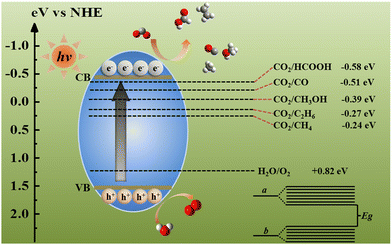
The majority of materials used in photocatalysis are semiconductors and semiconductor-like materials; thus, energy band theory plays an irreplaceable role in understanding photocatalytic procedures.15,70–72 The formation of the energy band is realized by the interaction between atoms.73–76 When atoms are close to each other, the original energy levels of the atoms split into a group of energy levels with small energy difference.77–82 Such a group of energy levels is called the energy band (Fig. 1). Because the energy difference of the energy levels in the a-band is very small, it can be regarded as continuous, and there is a zone without energy levels between the a-band and the b-band, which is called the band gap (Eg).83–86 When the atom is in the unexcited state, the electrons in the atom are arranged from the low-energy level to the high-energy level in turn, and the energy level filled with electrons is called the filled band. For the filled band, the energy level with the highest energy and closest to the empty energy band is denoted the valence band (VB), and the band that is not filled with electrons is the conduction band (CB).87,88 VB electrons driven by light energy remain in the CB and cross Eg, so the excited electron transition leads to the differentiation of positive and negative charges in semiconductors. Excited electrons are called photogenerated electrons (e−).89,90 After the transition, the VB loses negative charges and shows positive charges, which are called holes (h+).91 From a thermodynamic viewpoint, these e−–h+ pairs can cause the surface reduction and oxidation reactions only if their respective reduction and oxidation potentials are located between the CB and VB potentials. The standard redox potentials for CO2 reduction (Table 1) indicate that multi-electron reduction reactions are more conducive to the surface-active sites of semiconductors.| Reaction | E 0 (V) vs. NHE at pH = 7 |
|---|---|
| CO2 (g) + e− → CO2˙− | −1.9 |
| CO2 (g) + 2H+ + 2e− → HCOOH (aq) | −0.61 |
| CO2 (g) + 2H+ + 2e− → CO (g) + H2O (aq) | −0.53 |
| CO2 (g) + 4H+ + 4e− → HCHO (aq) + H2O (aq) | −0.48 |
| CO2 (g) + 6H+ + 6e− → CH3OH (aq) + H2O (aq) | −0.38 |
| CO2 (g) + 8H+ + 8e− → CH4 (aq) + 2H2O (aq) | −0.24 |
| 2CO2 (g) + 6H2O (aq) + 10e− → C2H2 (q) + 10OH− | −0.362 |
| 2CO2 (g) + 8H2O (aq) + 12e− → C2H4 (q) + 12OH− | −0.349 |
| 2CO2 (g) + 9H2O (aq) + 12e− → C2H5OH (aq) + 12OH− | −0.329 |
| 2CO2 (g) + 13H2O (aq) + 18e− → C3H7OH (aq) + 18OH− | −0.31 |
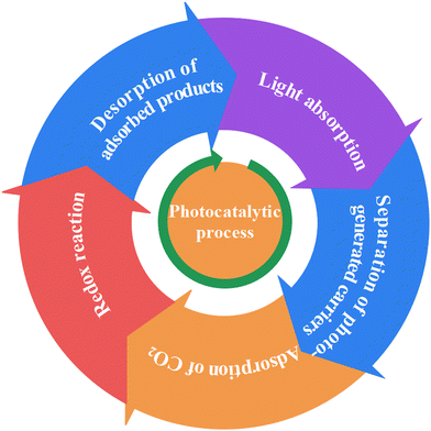
Photocatalytic reaction is the combination of photoreaction and catalytic reaction, which is driven by light energy to promote the photocatalyst to convert reactants into products. Chlorophyll, a natural photocatalyst in plants, is the earliest photocatalyst that human beings came into contact with. The reason why the photocatalyst has catalytic ability under illumination is that when sunlight is irradiated on the photocatalyst surface, it produces reductive e− and oxidizing h+.39,94–99 For photocatalytic CO2 reduction, CO2 combines with e−, chemisorption occurs and then it is further reduced to the target products (Fig. 1). Therefore, the photocatalytic process can be divided into the following 5 processes (Fig. 2),100,101 namely (i) light absorption, (ii) separation of photo-generated carriers, (iii) adsorption of CO2, (iv) redox reaction, and (v) desorption of adsorbed products. The overall photocatalysis efficiency is strongly dependent on the cumulative effect of these four consecutive steps, which can be expressed as below: ηc = ηabs × ηcs × ηcmt × ηcu, where ηc, ηabs, ηcs, ηcmt, and ηcu represent the photonic conversion, photon absorption, charge excitation/separation, charge migration/transport, and charge utilization efficiencies, respectively.102,103 The kinetic obstacles can be summarized as below: (i) the photocatalyst surface morphology affects photon absorption, (ii) the quick recombination kinetics of e−–h+ pairs is one of the most challenging obstacles, (iii) the low specific surface area and significant agglomeration of a nanostructured photocatalyst greatly decrease the surface redox kinetics and increase the diffusion barriers of the reagent, and (iv) as an uphill reaction, CO2 photoreduction, with its slow surface multi-electron reaction, results in the accumulation of photogenerated e− and h+ and thus, e−–h+ recombination and photocorrosion that consequently reduce their photocatalytic activity. Therefore, the kinetic factors are considered to be more important than the thermodynamic factors for the design and development of high-performance CO2 photoreduction catalysts.
2.2. The structure and application of LDHs
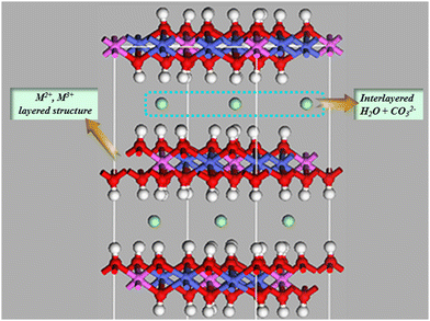
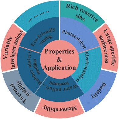
Layered double hydroxides (LDHs), also known as hydrotalcite-like compounds, are a group of 2D original existing and/or artificially synthesized anionic clay materials.104,105 These materials were exposed in Sweden in about 1842, but it was not until 1915 that Manasse reported the precise formula of the natural mineral hydrotalcite: [Mg6Al2(OH)16]CO3·4H2O.103,106 Then, in order to more precisely represent the newly developed members of the LDH family, [M1−x2+ Mx3+ (OH)2(An−)x/n]x+mH2O was introduced.107 Divalent metal ions (M2+) generally included Mg2+, Ni2+, Zn2+, Cu2+, etc. and trivalent metal ions (M3+) usually included Al3+, Fe3+, Ga3+, etc.94 The common monovalent (M+) and tetravalent (M4+) metal ions were Li+ and Ti4+; x denotes the mole fraction of M3+ in the metal ions in the range of 0.20–0.33. Interestingly, the radii of the metal ions M2+ and M3+ in LDHs were similar and the formed cationic plates were balanced by interlayer anions (An−) which could be both inorganic and organic anions (e.g. C6H4(COO)22−, CO32−, Cl−, NO3−, SO42−) (Fig. 3).108–117This material has been developed and used extensively since its emergence as a material with a particularly versatile structure. Its diverse properties (such as rich reactive sites,118 large specific surface area,119,120 basicity,41,121,122 variable interlayer anions,42,121,123 structural memory capabilities,116,124 and so on) allow for a wide range of applications. For instance, He et al. constructed a free-standing electrode FeNi-LDH/CoP/carbon cloth (CC) with an open and hierarchical heterostructure for the oxygen evolution reaction (OER), and FeNi-LDH/CoP/CC shows an extremely small Tafel slope of 33.5 mV dec−1, a large TOF of 0.131 s−1 at η = 254 mv, and a high stability over ∼18.5 h without degradation.125 Then, Iqbal et al. developed an efficient and facile synthetic method for the preparation of a multicomponent CDs/Ag@Mg-Al-Ce-LDH nanocatalyst by using carbon dots (CDs) which can facilitate the electron transfer and migration, as well as stabilize and improve the dispersion of Ag NPs.109 The large specific surface area and the layered structure composed of cations play an important role in the adsorption of pollutants in water bodies.113,126,127 And LDHs can also be invoked in other manufacturing applications, such as rubber material modifiers,128 Eco-friendly coatings,94 photocatalysts,129,130 and so on (Fig. 4). Herein, LDHs have been intensively studied as emerging photocatalytic materials for CO2 reduction, driven by national carbon peaking and carbon neutrality goals.
2.3. Advantages of LDHs for photocatalytic CO2 reduction
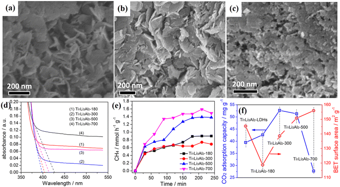 | ||
| Fig. 5 (a and b) The TEM images of Ti/Li/Al-LDHs under different calcination temperatures, (c) surface area and the CO2 adsorption capacity of Ti/Li/Al-LDHs calcined at different temperatures, (d) UV-Vis DRS spectra of Ti1Li3Al2-LDHs calcined at different temperatures, and (e) photocatalytic CH4 yields of Ti/Li/Al-LDHs calcined at different temperatures, and (f) surface area and the CO2 adsorption capacity of Ti1Li3Al2-LDHs calcined at different temperatures (Figures taken with permission from ref. 131 copyright 2023, Nature). | ||
Then, a novel approach where a monolayer of terminal amino groups of APS is grafted onto LDHs (APS/LDHs) for CO2 capture was explored by Tang et al.70 It was found that the enlarged layer spacing pillared by dodecyl sulfonate is beneficial to APS introduction. APS is tethered to the LDH laminates through covalent interaction. The incorporated amino groups contribute a lot to CO2 capture on APS/LDHs both through the zwitterion mechanism and weak bonding as confirmed by DRIFTS results. The CO2 adsorption capacity stabilizes at about 90 mg g−1 during the five cycles of adsorption–desorption, showing a great application potential in the temperature swing adsorption processes.
![[thin space (1/6-em)]](https://www.rsc.org/images/entities/char_2009.gif) :
:![[thin space (1/6-em)]](https://www.rsc.org/images/entities/char_2009.gif) Li
Li![[thin space (1/6-em)]](https://www.rsc.org/images/entities/char_2009.gif) :
:![[thin space (1/6-em)]](https://www.rsc.org/images/entities/char_2009.gif) Al elements in the TiLiAl-LDH structure. UV-Vis DRS (Fig. 6a) analysis indicates that all of those Ti/Li/Al-LDHs show outstanding optical absorption under ultraviolet light and the bandgap gradually changes on modifying the proportion of Ti
Al elements in the TiLiAl-LDH structure. UV-Vis DRS (Fig. 6a) analysis indicates that all of those Ti/Li/Al-LDHs show outstanding optical absorption under ultraviolet light and the bandgap gradually changes on modifying the proportion of Ti![[thin space (1/6-em)]](https://www.rsc.org/images/entities/char_2009.gif) :
:![[thin space (1/6-em)]](https://www.rsc.org/images/entities/char_2009.gif) Li
Li![[thin space (1/6-em)]](https://www.rsc.org/images/entities/char_2009.gif) :
:![[thin space (1/6-em)]](https://www.rsc.org/images/entities/char_2009.gif) Al elements. Then, along with the increase of the Ti
Al elements. Then, along with the increase of the Ti![[thin space (1/6-em)]](https://www.rsc.org/images/entities/char_2009.gif) :
:![[thin space (1/6-em)]](https://www.rsc.org/images/entities/char_2009.gif) Li
Li![[thin space (1/6-em)]](https://www.rsc.org/images/entities/char_2009.gif) :
:![[thin space (1/6-em)]](https://www.rsc.org/images/entities/char_2009.gif) Al molar ratio, Ti1Li3Al2-LDH exhibited the best surface area and CO2 adsorption capacity (Fig. 6c), and this phenomenon explains its highest photocatalytic activity under UV irradiation (Fig. 6b and d). This observation indicated that the adsorption capacity for CO2 should greatly determine the photocatalytic CO2 reduction activities of these obtained Ti/Li/Al-LDH samples. And the increased specific surface area affected by the different ratios of Ti
Al molar ratio, Ti1Li3Al2-LDH exhibited the best surface area and CO2 adsorption capacity (Fig. 6c), and this phenomenon explains its highest photocatalytic activity under UV irradiation (Fig. 6b and d). This observation indicated that the adsorption capacity for CO2 should greatly determine the photocatalytic CO2 reduction activities of these obtained Ti/Li/Al-LDH samples. And the increased specific surface area affected by the different ratios of Ti![[thin space (1/6-em)]](https://www.rsc.org/images/entities/char_2009.gif) :
:![[thin space (1/6-em)]](https://www.rsc.org/images/entities/char_2009.gif) Li
Li![[thin space (1/6-em)]](https://www.rsc.org/images/entities/char_2009.gif) :
:![[thin space (1/6-em)]](https://www.rsc.org/images/entities/char_2009.gif) Al molar ratios is exposing more active sites.
Al molar ratios is exposing more active sites.
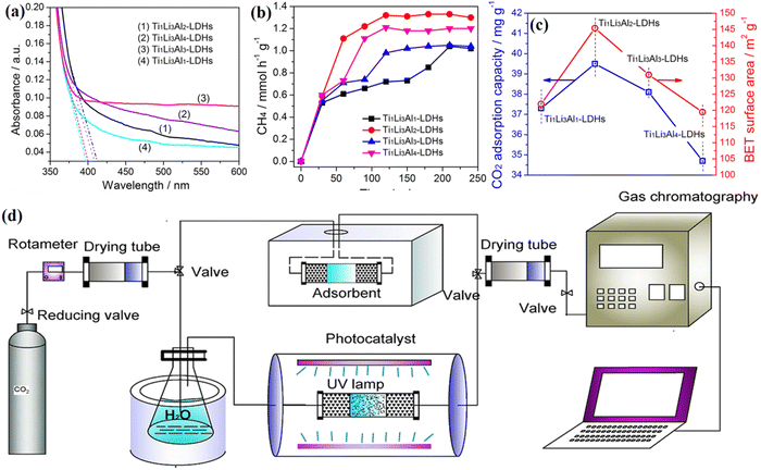 | ||
Fig. 6 UV-Vis DRS spectra of (a) Ti/Li/Al-LDHs with different Ti![[thin space (1/6-em)]](https://www.rsc.org/images/entities/char_2009.gif) : :![[thin space (1/6-em)]](https://www.rsc.org/images/entities/char_2009.gif) Li Li![[thin space (1/6-em)]](https://www.rsc.org/images/entities/char_2009.gif) : :![[thin space (1/6-em)]](https://www.rsc.org/images/entities/char_2009.gif) Al molar ratios. Photocatalytic CH4 yields of (b) Ti/Li/Al-LDHs with different Ti Al molar ratios. Photocatalytic CH4 yields of (b) Ti/Li/Al-LDHs with different Ti![[thin space (1/6-em)]](https://www.rsc.org/images/entities/char_2009.gif) : :![[thin space (1/6-em)]](https://www.rsc.org/images/entities/char_2009.gif) Li Li![[thin space (1/6-em)]](https://www.rsc.org/images/entities/char_2009.gif) : :![[thin space (1/6-em)]](https://www.rsc.org/images/entities/char_2009.gif) Al molar ratios. Surface area and the adsorption capacity of CO2 for (c) Ti/Li/Al-LDHs with different Ti Al molar ratios. Surface area and the adsorption capacity of CO2 for (c) Ti/Li/Al-LDHs with different Ti![[thin space (1/6-em)]](https://www.rsc.org/images/entities/char_2009.gif) : :![[thin space (1/6-em)]](https://www.rsc.org/images/entities/char_2009.gif) Li Li![[thin space (1/6-em)]](https://www.rsc.org/images/entities/char_2009.gif) : :![[thin space (1/6-em)]](https://www.rsc.org/images/entities/char_2009.gif) Al molar ratios, (d) schematic of the apparatus for CO2 adsorption and photocatalytic CO2 reduction (Figures taken with permission from ref. 131 copyright 2023, Nature). Al molar ratios, (d) schematic of the apparatus for CO2 adsorption and photocatalytic CO2 reduction (Figures taken with permission from ref. 131 copyright 2023, Nature). | ||
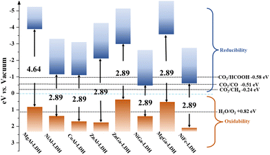
In addition to the category of atoms have a great modulating effect on the light absorption properties of LDHs, LDHs containing different kinds of metal ions have been achieved. One common approach is to identify precursors containing a certain ion prior to synthesis, while another approach uses ion exchange. Teng Wang employed the ion exchange method cleverly to immerse NiCo-LDH into 3 mM Fe(NO3)3·6H2O aqueous solution at room temperature. Product NiCoFe-LDH is successfully synthesized, which provides a convenient idea for the catalytic design of LDHs.132 Thereby, a detailed band gap structure of LDHs with different kinds of metal ions should be provided, as shown in Fig. 7.21,104,133 Fortunately, most of the LDH family can be excited in visible light and, from the inverted band position, their reduction capacity meets the energy required for CO2 conversion. The flexible synthesis method, adjustable composition, and unique microstructure allow for a wide range of tunability in the conductivity and band gap structure of LDHs. Therefore, the application of LDHs for photocatalytic CO2 reduction is inevitable.
| Molar concentrations of NaOH (M) | Average size (μm) | ||
|---|---|---|---|
| PH 9 | PH 10 | PH 11 | |
| 1 | 2.42 | 2.57 | — |
| 0.5 | 2.08 | 2.45 | 3.1 |
| 0.25 | 1.65 | 2.43 | 2.59 |
| 0.1 | 1.97 | 2.85 | 2.24 |
 | ||
| Fig. 8 Schematic illustration of the synthesis and photocatalytic application of the nano-hydroxide and TEM image showing the typical nanostructure of the nano-LDH (Figures taken with permission from ref. 129 copyright 2023, Nature). | ||
In summary, LDHs have a greater potential for development in the field of photocatalysis. This is mainly because the plasticity of their structure drives the favorable enhancement of their photoelectric properties. The unique layered structure provides superior conditions for the uniform distribution of reactive sites. Therefore, studies focusing on structural changes for photocatalytic CO2 reduction enhancement are pivotal to the application status of LDHs in the field of photocatalysis.
3. Methods for enhancing LDH photocatalytic CO2 reduction
3.1. Surface modification
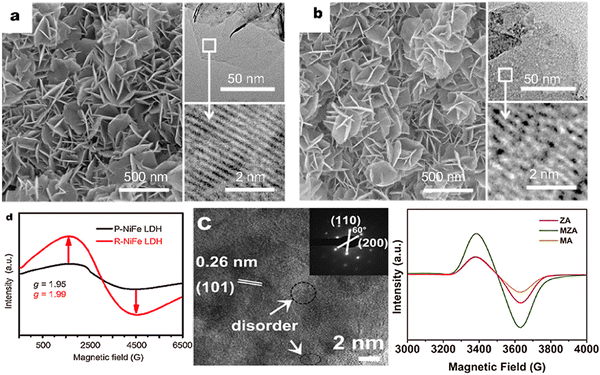 | ||
| Fig. 9 SEM images of the as-prepared (a) P-NiFe LDH and (b) R-NiFe LDH. The insets are the TEM and HRTEM images of P- and R-NiFe LDH, implying the structure with defects after reduction, (c) EPR characterization of P-NiFe LDH and R-NiFe LDH, (d) HR-TEM image and SAED pattern and (e) ESR spectra of the samples of ZnAl-LDH (Figures taken with permission from ref. 137 and 138 copyright 2023, Springer and Elsevier). | ||
Fan et al. proposed an interlayer anion-mediated CO2 reduction reaction in LDHs coupled with 5-HMF oxidation. In this subject paper, it was found that stirring the LDHs in potassium hydroxide solution led to an increase in defect density over time (Fig. 10a).139 These defects were observed to cause subtle changes in the structure of LDHs, which were reflected in the shift of peaks (110) in the XRD pattern (Fig. 10b and c). Also, EPR confirmed the presence of surface defects (Fig. 10d). Defect engineering has a significant impact on the photocatalytic activity of LDH materials due to the formation of electron traps at the defect sites that are favorable for electron aggregation. The vacancies created in the LDH layer can effectively modulate the band gap structure of LDHs, thus increasing their sensitivity to light. As a result of the UV-Vis DRS test in Fig. 11a–d, the defective engineering of the LDHs themselves to make them more suitable for photocatalytic reduction of CO2 is promising.
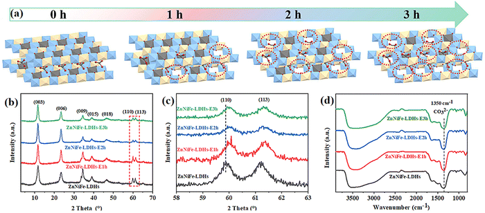 | ||
| Fig. 10 (a) Scheme of progressive etching of ZnNiFe-LDHs with alkali etching for different periods of time, (b and c) XRD patterns, and (d) EPR spectra (Figures taken with permission from ref. 139 copyright 2023, RSC). | ||
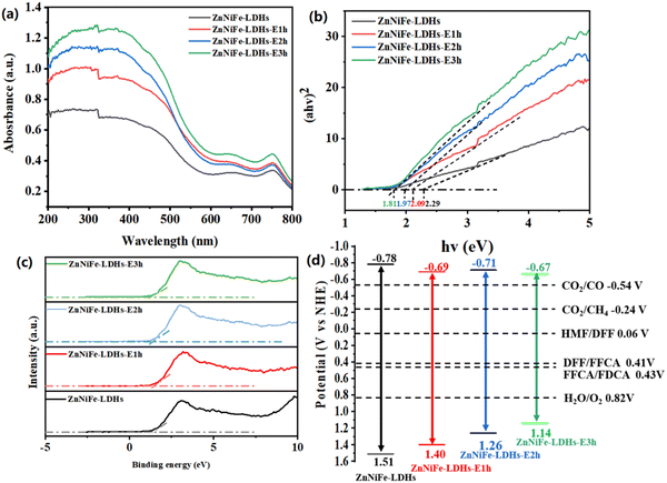 | ||
| Fig. 11 (a) UV-Vis DRS spectra, (b) energy band gap spectrum, (c) valence band spectrum, and (d) energy band structure of a series of ZnNiFe-LDHs before and after etching (Figures taken with permission from ref. 139 copyright 2023, RSC). | ||
3.2. Element doping
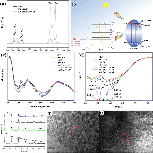 | ||
| Fig. 12 (a) Upconversion emission spectra of LDH, LDH:1% Er, and LDH:1% Er,2% Yb, (b) schematic diagram of photocatalytic CO2 reduction under the irradiation of UV-Vis and NIR light, (c) UV-Vis DRS, (d) band-gap energies of the as-prepared samples, (e) XRD patterns of different contents of Er3+ doped LDH, (f and g) HRTEM images of pure LDH, LDH:1% Er (Figures taken with permission from ref. 147 copyright 2023, Elsevier). | ||
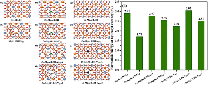 | ||
| Fig. 13 Optimized structural models of (a) MgAl-LDH, (b) MgAl-LDH with one OH vacancy (MgAl-LDH-VOH), (c) Co-MgAl-LDH, (d) Co-MgAl-LDH with one OH vacancy (Co-MgAl-LDH-VOH), (e) Co-MgAl-LDH with one adjacent OH vacancy (Co-MgAl-LDH-VOH-A), (f) Co-MgAl-LDH with two OH vacancies (Co-MgAl-LDH-VOH-2), (g) Cr-MgAl-LDH, (h) Cr-MgAl-LDH with one OH vacancy (Cr-MgAl-LDH-VOH), (i) Cr-MgAl-LDH with one adjacent OH vacancy (Cr-MgAl- LDH-VOH-A) and (j) Cr-MgAl-LDH with two OH vacancies (Cr-MgAl-LDH-VOH-2) (atoms in different colors: yellow-Mg, light blue-Al, green-Co, blue-Cr, red-O, white-H), (k) Formation energy of the hydroxyl vacancy (VOH) of different defect sites on MgAl-LDH, Co-MgAl-LDH and Cr-MgAl-LDH (Figures taken with permission from ref. 149 copyright 2023, Elsevier). | ||
Subsequently, CO2 surface reaction is also analyzed by DFT calculation based on Co and Cr-doped LDHs. The first step for CO2 reaction is the adsorption of a CO2 molecule on the doped metal sites. Around the hydroxyl vacancy of MgAl-LDH-VOH, it may provide two active sites for the adsorption of CO2 (the Al and the Mg site). At the same time, Cr and Co are directly selected as the potential active sites for the reaction. The optimized structural models of CO2 adsorption over four metal sites (Fig. 14a–d) and the calculated CO2 adsorption energies are shown in Fig. 14e. From the images of the adsorption models, the CO2 molecule is obviously bent and the stable structure is broken after adsorption. For MgAl-LDH-VOH, the adsorption energy of CO2 is about −2.59 eV on the Al site while the adsorption energy of CO2 is about −2.47 eV on the Mg site. Therefore, CO2 prefers to bond to the Al site on MgAl-LDH-VOH and the Mg site will be discarded in the following calculation. The adsorption energies of CO2 on Co-MgAl-LDH-VOH and Cr-MgAl-LDH-VOH are −2.83 eV and −2.70 eV. It is found that the doped metal could enhance CO2 adsorption and Co-MgAl-LDH exhibits the advantage of CO2 adsorption compared with Cr-MgAl LDH. In addition to this, a possible reaction mechanism is suggested in the article (Fig. 14f):
| CO2 + * + H+ + e− = *CO2 | (1) |
| *CO2 + H+ + e− = *COOH | (2) |
| *COOH + H++ e− = *CO + H2O | (3) |
| *CO = * + CO | (4) |
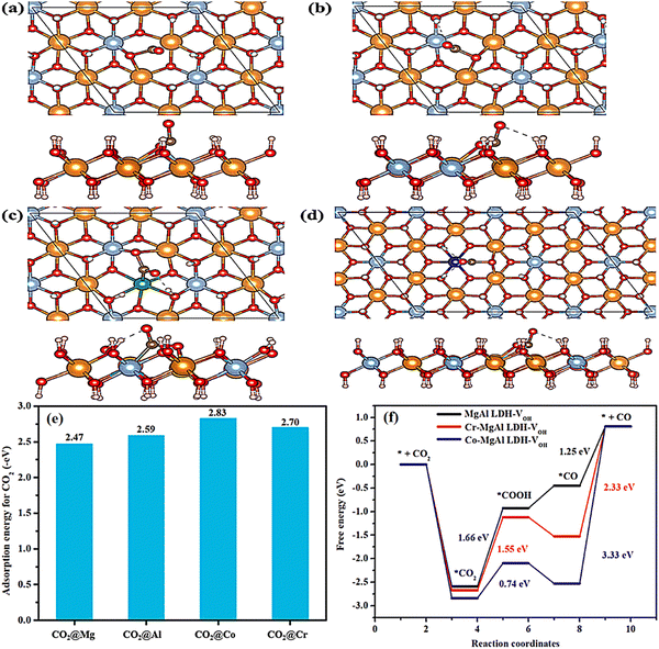 | ||
| Fig. 14 Optimized structural models of CO2 adsorption over (a) Mg, (b) Al, (c) Co and (d) Cr sites (Atoms in different colors: yellow-Mg, light blue-Al, green-Co, blue-Cr, red-O, white-H, black-C), (e) CO2 adsorption energies over different metal sites, and (f) free energy diagram describing the COOH* intermediate from CO2 to CO over three LDHs (Figures taken with permission from ref. 149 copyright 2023, Elsevier). | ||
According to the largest free energy change of the electron-involved reaction step, the CO2 reduction activity trend is that Co-MgAl-LDH-VOH > Cr-MgAl-LDH-VOH > MgAl-LDH-VOH. But in the CO2 surface reaction, Cr-MgAl-LDH is not optimal in CO2 adsorption and electrochemical reduction but its advantage lies in the release of CO.
Doping engineering is effective in enhancing the performance of LDHs in photocatalytic reduction of CO2, but doping with metal ions becomes preferable due to the structure of LDHs. For example, Khan et al. induced facile hydrothermal methodology in the synthesis of La incorporated CoAl-LDH nanoplates with different doping ratios, which exhibited promotional performance with the optimum quantity of Co2Al0.95La0.05-LDH.14 The influence is mainly ascribed to the substitution of Al3+ with La3+ and the synergistic effect of heterogeneous Co2+/Al3+-La3+ with mixed valences. The optimized doping of La resulted in remarkable photocatalytic activity, leading to enhanced production of CO (25.5 μmol gcat−1 h−1) and CH4 (21.80 μmol gcat−1 h−1). Compared to pure LDH, more oxygen vacancies and enhanced basicity caused by the addition of La greatly contribute to the photocatalytic CO2 reduction of Co2Al0.95La0.05-LDH. In addition, similar work has been completed by Deyang Li.150 The Cu-doped ZnAl-LDHs with a good layer structure are prepared by the coprecipitation method. The doping of Cu2+ into the LDH sheets improves the visible light absorption capacity of the ZnAl-LDHs.
3.3. Surface plasma resonance (SPR) effect
Noble metal nanoparticles can greatly promote the photocatalytic reaction, so it is a common method to support noble metals to improve the photocatalytic activity of photocatalysts.151,152 Interestingly, when the diameter of the loaded noble metal nanoparticles is less than 2 nm, they exhibit semiconductor properties, while the nanoparticles with a diameter greater than 2 nm improve the photocatalytic activity through SPR.47,91,153–155 Noble metal nanoparticles usually affect photocatalytic activity directly or indirectly. The direct enhancement means that noble metal nanoparticles react directly with catalyzed substances or through contact with active substances such as free radicals. The indirect way is that the noble metal nanoparticles interact with the semiconductor, then, the semiconductor reacts with the reactant.114,156–158 When the noble metal nanoparticles interact with the semiconductor, the catalytic mechanism is that light irradiation on the photocatalyst causes the noble metal nanoparticles to generate SPR.159–161 Electrons generated by heat on the metal surface cross the Schottky barrier between the metal nanoparticles and the semiconductor.161–164 Subsequently, electrons are injected into the CB of the semiconductor, thus increasing the density of photogenerated carriers in the semiconductor and prolonging the residence time of photogenerated carriers on the semiconductor surface, thus promoting the catalysis. Therefore, the conditions of the SPR effect should be followed: I. The wavelength of incident light is close to or less than the radius of the nanoparticles. II. The nanoparticles have the lens effect. III. The photon density on the surface of the precious metal is higher than that on the semiconductor side.165,166 When the noble metal nanoclusters recombine with semiconductors, e− and h+ are usually produced under illumination, and e− will transfer to the semiconductors or react with the solvents to produce singlet oxygen. This unique photocatalytic gain effect of noble metal nanoparticles can not only act on other semiconductors, but also improve the photocatalytic performance of LDHs. Moreover, LDHs acting as a functional carrier has an unexpected effect on the distribution of such small-sized particles, and it is surprising to prevent the agglomeration of noble metal nanoparticles and cause the uniform distribution of reactive sites.160Zhang and his co-workers reported that Ag@U-LDH acts as a highly efficient photocatalytic CO2 reduction catalyst.167 The Ag loaded on the U-LDH surface was identified by HRTEM (Fig. 15a). The supported Ag nanoparticles disperse on U-LDH nanosheets with uniform size. The lattice fringe spacing of Ag is 0.236 nm corresponding to the (111) plane. The size distribution diagram indicates an average Ag nanoparticle size of 5.7 nm with a narrow distribution (Fig. 15b). Therefore, Ag nanoparticles are successfully loaded on the LDH surface and Ag@U-LDH delivers a higher CO evolution rate of 757 μmol g−1 h−1 than U-LDH (105 μmol g−1 h−1) and a high CO selectivity of 94.5% (Fig. 15c). The enhancement mainly stems from the fact that Ag on the surface of LDHs induces a lower formation energy for the *COOH intermediate (Fig. 15d). The conclusion that SPR of precious metals plays a key role in consuming the formation of reactive intermediates on the surface of LDHs is effectively argued. In the study of Shogo Kawamura, the UV absorption characteristics of the LDH photocatalyst with the SPR effect and photocatalytic CO2 reduction mechanism of the LDH-based photocatalyst loaded with noble metal nanoparticles were investigated and it was found that the SPR effect induces a red-shift in the absorption band when the semiconductor is illuminated, and the light utilization efficiency increases (Fig. 15e and f).168 An efficient photocatalyst for the conversion of CO2 into fuel was prepared on the basis of the self-assembly of Ag or Au nanoparticles with [Zn3Ga(OH)8]2CO3-mH2O layered double hydroxide (Zn3Ga|CO3 LDH). The TEM of Au/Zn3Ga|CO3-reconst makes it clear that metal nanoparticles uniformly disperse on the surface of the LDHs (Fig. 15g). The UV-Vis DRS absorption characteristic peaks of the as-prepared photocatalyst are distributed at 411 and 555 nm attributable to Ag and Au nanoparticles, respectively. And the photocatalytic mechanism with the involvement of SPR is shown in Fig. 15h; the electrons created by SPR of Au are not able to cause photocatalytic CO2 reduction, whereas Eg electrons in the LDHs excited by UV light are trapped in Au and then transferred to CO2-derived species. Due to the higher potential of excited state electrons on Au than on the CB of Zn3Ga|CO3, the oxidation is more favorable for CO formation under UV light.
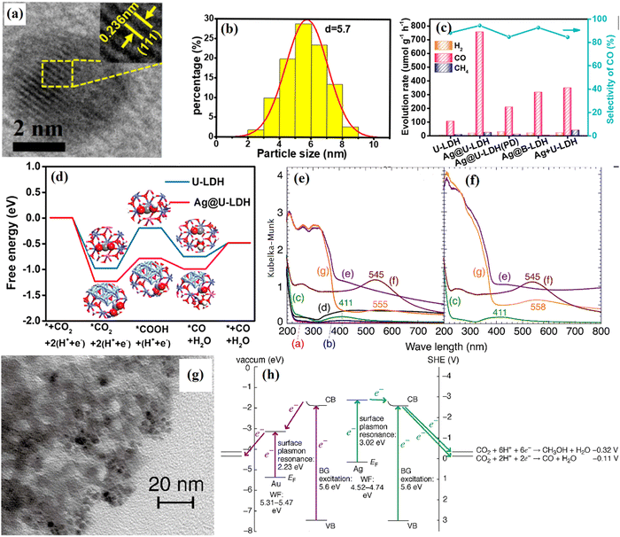 | ||
| Fig. 15 (a and b) HRTEM image of Ag@U-LDH, lattice photograph, and size of Ag nanoparticles, (c) catalytic evaluation of CO2 photoreduction under the irradiation of AM 1.5G filter, 100 mW cm−2 on the series of catalysts; Ag+ U-LDH is Ag@U-LDH that is sonicated in water for a certain time, (d) free energy diagrams of CO2 reduction to CO on U-LDH and Ag@U-LDH (Figures taken with permission from ref. 75 copyright 2023, ACS). (e) UV-Vis DRS spectrum for as-synthesized samples of (a) Zn3Ga|CO3, (b) Ag/Zn3Ga|CO3-IE 353-15, (c) Ag/Zn3Ga|CO3-IE 373-15, (d) Ag/Zn3Ga|CO3-IE 373-180, (e) Ag/Zn3Ga|CO3-reconst, (f) Au/Zn3Ga|CO3-IE, and (g) Au/Zn3Ga|CO3-reconst, and (f) samples that have been photocatalytically tested for 5 h of (c) Ag/Zn3Ga|CO3-IE 373-15, (e) Ag/Zn3Ga|CO3-reconst, (f) Au/Zn3Ga|CO3-IE, and (g) Au/Zn3Ga|CO3-reconst, (g) HRTEM image of Au/Zn3Ga|CO3-reconst, (h) the energy diagram and electron flow in (right) Ag/Zn3Ga|CO3-IE 373-15 and (left) Au/Zn3Ga|CO3-reconst during photocatalytic CO2 reduction (Figures taken with permission from ref. 167 and 168 copyright 2023, Elsevier). | ||
3.4. Heterojunction
Modification of the internal structure of LDHs has indeed led to significant progress in photocatalytic CO2 reduction; however, a lower concentration of photogenerated carriers and fast photogenerated carrier recombination are still a great challenge. Therefore, to overcome the common drawback above, researchers have proposed the form of two semiconductors connected, namely a heterojunction. In addition, according to the electron migration paths and structures, heterojunctions have been classified into type-II, all-solid-state indirect heterojunctions and all-solid-state direct heterojunctions.169,170 Practically, for the photocatalysis of CO2, heterojunctions can also be considered as excellent candidates due to the enhancement toward optical properties.122,171–173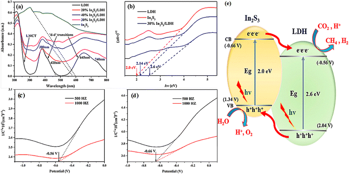 | ||
| Fig. 16 UV-Vis DRS for pure In2S3, pure LDH and In2S3/LDH composites (a) and (αhν)1/2versus energy (hν) for the band gap energies of pure In2S3 and pure LDH (b), Mott–Schottky plots measured for pristine LDH (c) and In2S3 and (d and e) CO2 photoreduction mechanism on the In2S3/LDH composites (Figures taken with permission from ref. 74 copyright 2023, ACS). | ||
In addition to the common SEM and TEM, XPS can also reflect the interactions between semiconductors. Zhang et al. reported a 3D dahlia-like NiAl-LDH/CdS type-II heterosystem coordinating with a 2D/2D interface, and in situ growth of CdS on the surface of the floral spheres of LDHs by a two-step hydrothermal method (Fig. 17a).124 XPS spectrum is a suitable implement to be used to verify the elemental composition (Ni, Al, Co, S, C and O) of the photocatalyst and the intimate contact between the two semiconductors (Fig. 17b). In view of the high-resolution spectrum results (Fig. 17c–f), the main characteristic peaks of both Ni and Al are red-shifted (reduced binding energy) and those of Cd and S are blue-shifted (increased binding energy), which indicates the interaction between NiAl-LDH and CdS. Moreover, according to the variation of the binding energy for NiAl-LDH and CdS after the integration, the electron migration from NiAl-LDH to CdS can be proposed. The observed change in binding energy implies a possible path of migration for photogenerated carriers, which aligns with the characteristics of a type-II heterojunction. And the 3D hierarchical NiAl-LDH/CdS heterosystem presents 12.45 μmol g−1 h−1 of CO production (3.3 and 1.6 folds of pristine NiAl-LDH and CdS) with 96% selectivity and superior stability.
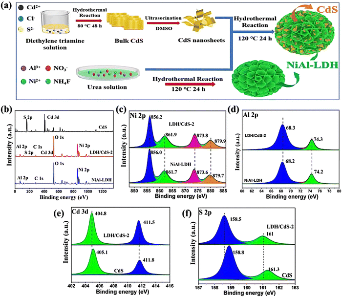 | ||
| Fig. 17 (a) Illustration of the synthesis of the 3D hierarchical NiAl-LDH/CdS hybrid, (b) XPS survey spectra of NiAl-LDH, CdS and NiAl-LDH/CdS-2, (c) Ni 2p, (d) Al 2p, (e) S 2p, (f) Cd 3d and core-level XPS spectra (Figures taken with permission from ref. 124 copyright 2023, Elsevier). | ||
The photoelectric properties of two-dimensional lamellar LDHs are exceptional and can be further improved by creating type-II heterojunction photocatalysts with other semiconductors. Additionally, the heterojunction-reinforced structure is more advantageous for the photocorrosion resistance of LDH-based composite photocatalysts (Fig. 18a).174 The TiO2/NiAl-LDH core-shell hybrid was obtained via a synthesis route involving hydrothermal and calcination treatments but not involving environmentally toxic solvents or surfactants. As shown in Fig. 18b, the result of the steady-state PL spectra means that TiO2/NiAl-LDH is exposed to light, and it experiences a decrease in the fluorescence effect of photogenerated carriers and a significant improvement in the utilization efficiency of photogenerated carriers. At the same time, the impedance of the composite photocatalyst is reduced (Fig. 18d), which is more favorable for the overall transport of the large number of photogenerated carriers generated during illumination (Fig. 18c). This target TiO2/LDH core-shell hybrid exhibits the highest CH4 evolution among the tested samples, with a total yield of 5.14 μmol over 5 h, equating to a rate of 20.56 μmol g−1 h−1, representing remarkable 25.7- and 5.0-fold improvements in CH4 production compared with those of reference TiO2 NPs and TiO2 HSs, respectively. Therefore, from the above examples it can be shown that LHD semiconductors can form close contacts with other semiconductors to improve the LDH photoelectrochemical properties and photocatalytic activity.
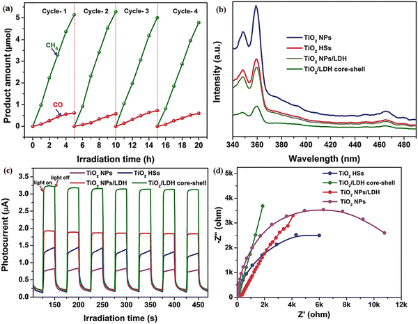 | ||
| Fig. 18 (a) Recycling tests of CH4 and CO evolution over the TiO2/LDH core-shell hybrid, (b) steady-state PL spectra, (c) photocurrent responses, and (d) EIS profiles of the TiO2 NPs, TiO2 HSs, TiO2 NPs/LDH, and TiO2/LDH core-shell hybrid sample (Figures taken with permission from ref. 174 copyright 2023, RSC). | ||
For all-solid-state indirect heterojunctions, excellent conductivity mediators present between the host semiconductor and the guest one, include Ag NPs, Au NPs, Pt NPs and graphite.57,173,179 Compared to liquid-phase media, this approach solves the low dispersion rate of ions that restricts the charge carrier stimulation; however, it causes a shielding effect. Despite such drawbacks, its application for optimizing LDH-based photocatalysts is still effective. It can also show unique advantages over type-II heterojunctions, such as outstanding redox ability. In addition, Z-Scheme heterojunctions show a similar effect to the type-II heterojunctions, including improving the photoelectric properties and catalytic activity of LDH-based photocatalysts. In order to more clearly understand the superiority of Z-Scheme heterojunctions in the field of LDH-based photocatalytic CO2 reduction and clearly distinguish between Z-Scheme heterojunctions and type-II heterojunctions, a novel Z-Scheme mechanism photocatalyst of Ag-modified α-Fe2O3 spherical particles interspersed on hierarchical flower-like NiAl-LDH microspheres (α-Fe2O3/Ag/NiAl-LDH, designated as FALDH) was successfully prepared by a combined in situ hydrothermal and grafting strategy.180 Ascribed to the strong interaction between the NiAl-LDH microspheres and the highly-dispersed Ag/α-Fe2O3 particles, boosted CO2 adsorption capacity and optimized bandgap from α-Fe2O3, and increased utilization efficiency of light from Ag, the optimal sample of FALDH-5/10 exhibits significantly enhanced photocatalytic activity for CO2 reduction to CO under simulated sunlight without any sacrificial reagents and photosensitizers. Photocurrent and EIS measurements were carried out to explain the photoelectric superiority of FALDH-5/10, as shown in Fig. 19a and b. And in terms of fluorescence lifetime (Fig. 19c), the heterojunction improves the residence time of photogenerated carriers on the semiconductor surface, thus enhancing the utilization efficiency of photogenerated carriers. For all-solid-state indirect heterojunctions, there is evidence that the structure of semiconductor (I)-mediator-semiconductor (II) plays a crucial role in this system. Chaorong Chen181 prepared a novel Z-scheme AgBr@Ag/CoAl-LDH photocatalyst, and the Ag NPs are precisely controlled between the two semiconductors, as shown in Fig. 20a and b. Then, one of the main obstacles is that the shielding effect always exists in the Z-Scheme, which is mainly caused by the form of semiconductor (I)-mediator-semiconductor (II).
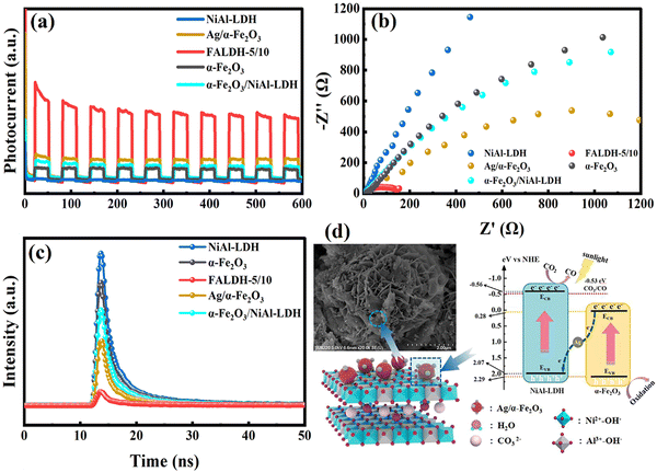 | ||
| Fig. 19 (a) Photocurrents, (b) EIS spectra, (c) time-resolve fluorescence decay spectra, and (d) the mechanism diagram of FALDH-5/10 (Figures taken with permission from ref. 180 copyright 2023, Elsevier). | ||
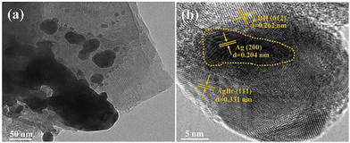 | ||
| Fig. 20 (a) TEM and (b) HR-TEM of 10% AgBr@Ag/LDH (Figures taken with permission from ref. 181 copyright 2023, Elsevier). | ||
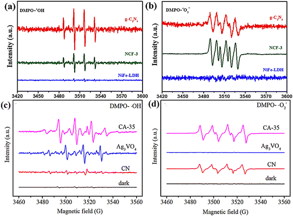
Then, the significant difference for the migration route of photogenerated carriers that exists in Z-Scheme heterojunctions and type-II heterojunctions can be reflected in the ESR spectrum. For example, an enhanced Z-Scheme g-C3N4/Ag3VO4/rGO heterojunction photocatalyst was successfully prepared by Gao et al.182 for photocatalytic CO2 reduction and a type-II g-C3N4 (CN) foam/LDH heterojunction monolith (NCF) was fabricated through growing NiFe-LDH in situ on a porous CN foam substrate by Zhu et al.117 It is obvious from the ESR (Fig. 21a–d) comparison that the Z-Scheme heterojunction releases the full reduction and oxidation capacity of the semiconductor, which is clearly superior to the type-II heterojunction.
 | ||
| Fig. 22 The electrostatic potentials of (a) NiIn-LDH and (b) In2S3, and (c) the DOS of NiIn-LDH/In2S3 (Figures taken with permission from ref. 21 copyright 2023, Elsevier). | ||
Sun et al. synthesized a novel CsPbBr3/NiFe-LDH (CPB/LDH) direct Z-Scheme heterojunction photocatalyst using an easy impregnation, then applied it for artificial photocatalytic CO2 reduction.111 A suitable band gap structure is necessary for semiconductors to form a direct Z-Scheme heterojunction. UV-Vis DRS spectra of NiFe-LDH and CPB/LDH-x (x = 1–3), VB-XPS spectra and Tauc plots of CPB and NiFe-LDH show the band gap structures of the semiconductors (Fig. 23a–d). NiFe-LDH as a semiconductor with strong oxidizing properties becomes the oxidizing part of the catalyst, while PBC is mainly responsible for the reduction of CO2. And from the experimental results, it can be seen that the formation of NiFe-LDH-based heterojunctions improved the adsorption capacity of CO2, and the level of photocatalytic reduction of CO2 was substantially increased (product yield rate of pristine NiFe-LDH (7.4 μmol g−1 h−1) is comparatively lower than that of the CPB/NiFe-LDH-x (x = 1–3) catalysts). Moreover, the electron consumption rate of CPB/NiFe-LDH-2 (39.58 μmol g−1 h−1) is about 2-fold higher than that of pristine NiFe-LDH and CPB, which is counted by Relectrons = 2R(CO) + 8R(CH4) (Fig. 23f and g). This indicated that by adjusting the content of CPB/NiFe-LDH, the photogenerated carriers in the Z-Scheme can be increased efficiently, which casts controllable Z-Scheme photocatalytic reduction performance. The advantages of the all-solid-state direct heterojunction applied in LDH-based photocatalysts are also obvious: the elimination of the interposer is replaced by a tight coupling between the two semiconductors, which greatly shortens the migration path of the photogenerated carriers and eliminates the cost of the interposer compared to the indirect Z-Scheme heterojunction. Combining the advantages of type-II heterojunctions and indirect Z-Scheme heterojunctions with reduced cost may make it easier to be applied in the field of CO2 reduction by LDH photocatalysis.
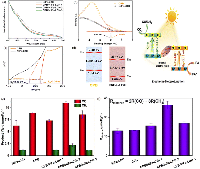 | ||
| Fig. 23 (a) UV-Vis DRS spectra of NiFe-LDH and CPB/LDH-x (x = 1–3), (b and c) VB-XPS spectra and Tauc-plots of CPB and NiFe-LDH, (d) energy band alignments of CPB and NiFe-LDH, (e) the product yield rates of the photocatalysts, (f) the electron consumption of pristine NiFe-LDH, CPB and CPB/NiFe-LDH-x (x = 1–3) (Figures taken with permission from ref. 111 copyright 2023, RSC). | ||
In short, LDH-based catalysts have a bright future for photocatalytic CO2 reduction applications, and the tunability of their crystal structure allows for better coupling with other semiconductors, resulting in tight junctions. The large specific surface area not only provides sufficient loading sites for the distribution of active sites, but also provides naturally advantageous conditions for CO2 adsorption. Although their photoelectric properties are weak and their electrical conductivity is not strong, they are well improved by heterojunctions, noble metal loading, and surface engineering. Therefore, the application of LDH materials in photocatalysis is worthy of deeper exploration and development.
We also compared these improved solutions for increasing the catalytic activity of LDHs, as shown in Table 3. Pure metal oxides can be used as semiconductor photocatalysts, however the performance in terms of activity in photocatalytic CO2 reduction is mediocre compared to LDHs containing this metal. And among those methods, heterojunctions for the enhancement of photocatalytic activity are stronger than others. The density and utilization efficiency of photogenerated carriers may play a more important role in the photocatalytic process. Therefore, it is even more important to increase the lifetime of photogenerated carriers in catalysts. In our mind, to achieve the best catalytic effect, the development of modified LDH derivatives as heterojunction photocatalysts would be a wise choice and a favorable direction.
| Photocatalysts | Light source | Type | Reducing agent | Products | Performance (μmol g−1 h−1) | Ref |
|---|---|---|---|---|---|---|
| ZnO | UV-Vis DRS | — | H2O | CO | 0.7 | 183 |
| Zn1Al1-LDH | UV-Vis DRS | — | H2O | CO | 7.6 | 183 |
| Zn1Al2-LDH | UV-Vis DRS | — | H2O | CO | 6.5 | 183 |
| Zn1Al3-LDH | UV-Vis DRS | — | H2O | CO | 0 | 183 |
| Mg1Al1-LDH | UV-Vis DRS | — | Acetonitrile | CO/CH4 | 202.2/120.7 | 184 |
| Ni3Al1-LDH | 250 W Xe-lamp | — | H2O | CO | 1.63 | 185 |
| LDH:1% Er, 3% Yb | Visible | Elements doping | H2O | CO | 13.20 | 147 |
| NiCo2O4 HCs | Visible | Calcination | 2,2-Bipyridine & acetonitrile | CO | 10.5 | 186 |
| MgCo2O4 | Visible | Calcination | 2,2-Bipyridine & acetonitrile | CO | 6.3 | 186 |
| Ag/NiAl-LDH | 250 W Xe-lamp | Noble metal | H2O | CO | 2.25 | 185 |
| Pt/ZnCr-LDH | UV | Noble metal | H2O | CO | 7.8 | 187 |
| Au/ZnCr-LDH | UV | Noble metal | H2O | CO | 3.3 | 187 |
| Pd/ZnCr-LDH | UV | Noble metal | H2O | CO | 4.6 | 187 |
| g-C3N4/NiAl-LDH | 300 W Xe-lamp | Type-II | Nafion solution | CO | 8.2 | 130 |
| NiAl-LDH/CdS | 300 W Xe-lamp | Type-II | H2O | CO | 12.45 | 124 |
| a-Fe2O3/Ag/NiAl-LDH | 250 W Xe-lamp | Z-Scheme | H2O | CO | 12.7 | 180 |
| CoZnAl-LDH/RGO/gC3N4 | 300 W Xe-lamp | Z-Scheme | H2O | CO | 10.11 | 122 |
| CuO/CoAl-LDH | 250 W high-pressure Hg-lamp | Z-Scheme | Isopropanol | CO | 283.26 | 188 |
| g-C3N4/CoNiFe-LDH | 300 W Xe-lamp | Z-Scheme | H2O | CO | 42 | 116 |
4. Conclusion and outlook
This review comprehensively summarizes recent advances in LDH-based photocatalysts and their application towards photocatalytic CO2 reduction, and also highlights several main research strategies and potential future directions as shown below.One of the most important strategies is using LDHs as a precursor to prepare mixed metal oxides or LDOs. The 2D characteristics of the LDHs have an intrinsic high density and uniform distribution of cations within their structures, which reveals a decisive advantage for designing a photocatalyst with a high density of active sites for photocatalytic CO2 reduction. The use of bimetallic or trimetallic layered hydroxides also has the advantage that the number of active sites can be adjusted by changing the ratio of cations and the type of cationic reaction sites can also have an obvious effect on the photocatalytic reduction of CO2.
Another important direction focuses on the design of LDH-based nanohybrids. Here, the motivation is to enhance the intrinsically short lifetimes of the LDH charge carriers and promote their extraction. Examples of type-II and Z-Scheme heterojunctions have been reported. Notably, many recent works indicate a dramatic effect of the synthesis method and preparation conditions on the type and morphology of the LDH-based nanohybrids. These affect the structural degree of the materials and, in turn, the electronic interactions between the composite components, thus resulting in synergistic effects.
Other works highlight the role of surface-loaded plasmonic materials in enhancing the catalytic activity of the LDH-based nanohybrids. Noble metal nanoparticles usually affect photocatalytic activity directly or indirectly. Although both the direct path (that means noble metal nanoparticles react directly with catalyzed substances or through contact with active substances) and the indirect route (that the noble metal nanoparticles interact with the semiconductor, then, the semiconductor reacts with the reactant) all can promote the performance of photocatalytic CO2 reduction, the mechanism still needs to be determined in detail.
Promoting charge carrier separation is also an important function for LDHs that is favorable for the second composite component to increase light absorption and generation of charge carriers. Here, the formation of intimate interfacial contacts in 2D/2D nanocomposites and heterojunctions often yields enhanced charge separation efficiencies. Based on PL, EIS and photocurrent studies, these works further highlight the role and beneficial effect of such a heterojunction. In addition, some of the works also focused on using LDHs as cocatalysts and active catalytic sites and their role in enhancing performance and charge separation efficiency. Due to their compositional and structural characteristics, LDHs can be considered a tunable catalytic platform to address kinetically more complex reactions such as CO2 reduction. However, some important challenges and insights need to be further discussed and understood, as addressed in the following section:
(i) LDH-derived catalysts and their composite catalysts have shown great potential in the field of photocatalytic CO2 reduction. However, further studies need to unravel the charge transfer directions of the electrons and holes after charge separation. There are still only a few works that have provided detailed insights into the overall mechanism of photocatalytic CO2 reduction.
(ii) The synthesis of pristine LDHs and highly crystalline LDH-based materials has always been difficult. The common methods for preparing these materials are co-precipitation, in situ growth, self-assembly, and hydrothermal and solvothermal methods, which unfortunately have difficulties in controlling the size distribution and layer thickness of the resulting LDH flakes. Achieving highly active and efficient photocatalytic effects requires an effort to reduce the crystal size and weaken the thickness of the flakes. The exfoliation method has attracted much attention because of its ability to obtain LDHs with ultra-thin and separated layers, high surface area, and extended light-harvesting capability. However, only a few studies have reported their use for photocatalytic CO2 reduction processes. Future developments on LDH stripping could open new perspectives for other photocatalytic reactions.
(iii) Although there have been significant developments in the catalytic mechanism, synthesis, design and characterisation of photocatalysts developed on the platform of LDHs, there is still a long way to go before they can move from the laboratory to the practical production and commercial level.
In the future, LDHs, an emerging material for photocatalytic CO2 reduction, will bring a unique opportunity and a great challenge. This review provides meaningful guidance for the rational design and development of LDH-based photocatalysts with high activity, high stability, environmental friendliness and low cost. There is no doubt that there will be a place for LDH-based photocatalysts in the emerging field of photocatalytic reduction of CO2.
Conflicts of interest
There are no conflicts of interest to declare.Acknowledgements
This work was supported by the National Natural Science Foundation of China (grant no. 52203110), the Knowledge Innovation Program of Wuhan-Shuguang Project (grant no. 2022010801020216), and the Scientific Research Foundation of Fujian University of Technology (grant no. GY-Z220182).References
- Q. Wu, X. Yang, J. Yang, P. Liu, G. Ding, Z. Chen and G. Liao, J. Colloid Interfance Sci., 2023, 644, 238–245 CrossRef CAS PubMed.
- X. Liu, Y. Zhang, X. Guo and H. Pang, Adv. Fiber Mater., 2022, 4, 1463–1485 CrossRef CAS.
- G. Liao, Y. Gong, L. Zhang, H. Gao, G.-J. Yang and B. Fang, Energy Environ. Sci., 2019, 12, 2080–2147 RSC.
- G. Liao, C. Li, X. Li and B. Fang, Cell Rep. Phys. Sci., 2021, 2, 100355 CrossRef CAS.
- G. Liao, C. Li, S.-Y. Liu, B. Fang and H. Yang, Trends Chem., 2022, 4, 111–127 CrossRef CAS.
- G. Liao, C. Li, S.-Y. Liu, B. Fang and H. Yang, Phys. Rep., 2022, 983, 1–41 CrossRef CAS.
- C. Li, H. Lu, G. Ding, Q. Li and G. Liao, Catal. Sci. Technol., 2023 10.1039/D3CY00242J.
- R. de_Richter and S. Caillol, J. Photochem. Photobiol. C: Photochem. Rev., 2011, 12, 1–19 CrossRef CAS.
- X. Fang, C. Chen, H. Jia, Y. Li, J. Liu, Y. Wang, Y. Song, T. Du and L. Liu, J. Ind. Eng. Chem., 2021, 95, 16–27 CrossRef CAS.
- D. Hong, L.-M. Lyu, K. Koga, Y. Shimoyama and Y. Kon, ACS Sustainable Chem. Eng., 2019, 7, 18955–18964 CrossRef CAS.
- R. Jia, C. He, Q. Li, S.-Y. Liu and G. Liao, Trends Biotechnol., 2022, 40, 1425–1438 CrossRef CAS PubMed.
- Z. Yan, G. Liao, X. Zou, M. Zhao, T. Wu, Y. Chen and G. Fang, J. Agric. Food Chem., 2020, 68, 8341–8349 CrossRef CAS PubMed.
- Z. Yan, B. Song, G. Fang, T. Wu, N. Chen, M. Zhao, X. Zou and G. Liao, ACS Sustainable Chem. Eng., 2021, 9, 10403–10423 CrossRef CAS.
- A. Ali Khan and M. Tahir, Energy Fuels, 2021, 35, 8922–8943 CrossRef CAS.
- B. Fang, Y. Xing, A. Bonakdarpour, S. Zhang and D. P. Wilkinson, ACS Sustainable Chem. Eng., 2015, 3, 2381–2388 CrossRef CAS.
- X. Hao, L. Tan, Y. Xu, Z. Wang, X. Wang, S. Bai, C. Ning, J. Zhao, Y. Zhao and Y.-F. Song, Ind. Eng. Chem. Res., 2020, 59, 3008–3015 CrossRef CAS.
- S. Liu, L. R. Winter and J. G. Chen, ACS Catal., 2020, 10, 2855–2871 CrossRef CAS.
- C. Li, W. Che, S. Y. Liu and G. Liao, Mater. Today Chem., 2023, 29, 101392 CrossRef CAS.
- J. Li, H. Huang, W. Xue, K. Sun, X. Song, C. Wu, L. Nie, Y. Li, C. Liu, Y. Pan, H.-L. Jiang, D. Mei and C. Zhong, Nat. Catal., 2021, 4, 719–729 CrossRef CAS.
- X. Li, Y. Sun, J. Xu, Y. Shao, J. Wu, X. Xu, Y. Pan, H. Ju, J. Zhu and Y. Xie, Nat. Energy, 2019, 4, 690–699 CrossRef CAS.
- X. Han, B. Lu, X. Huang, C. Liu, S. Chen, J. Chen, Z. Zeng, S. Deng and J. Wang, Appl. Catal., B, 2022, 316, 121587 CrossRef CAS.
- L. Cheng and Y. Ji, Green Energy Environ., 2022 DOI:10.1016/j.gee.2022.07.006.
- Y. Zhao, G. I. N. Waterhouse, G. Chen, X. Xiong, L. Z. Wu, C. H. Tung and T. Zhang, Chem. Soc. Rev., 2019, 48, 1972–2010 RSC.
- C. Li, G. Ding, X. Liu, P. Huo, Y. Yan, Y. Yan and G. Liao, Chem. Eng. J., 2022, 435, 134740 CrossRef CAS.
- C. Li, X. Liu, G. Ding, P. Huo, Y. Yan, Y. Yan and G. Liao, Inorg. Chem., 2022, 61, 4681–4689 CrossRef CAS PubMed.
- C. Li, X. Liu, P. Huo, Y. Yan, G. Liao, G. Ding and C. Liu, Small, 2021, 17, 2102539 CrossRef CAS PubMed.
- C. Li, Y. Zhao, X. Liu, P. Huo, Y. Yan, L. Wang, G. Liao and C. Liu, J. Colloid Interface Sci., 2021, 600, 794–803 CrossRef CAS PubMed.
- B. Yang, X. Li, Q. Zhang, X. Yang, J. Wan, G. Liao, J. Zhao, R. Wang, J. Liu, R. D. Rodriguez and X. Jia, Appl. Catal., B, 2022, 314, 121521 CrossRef CAS.
- Y.-J. Zhang, J.-Z. Cheng, Y.-Q. Xing, Z.-R. Tan, G. Liao and S.-Y. Liu, Mater. Sci. Semicond. Proc., 2023, 161, 107463 CrossRef CAS.
- W. Zhao, M. Ding, P. Yang, Q. Wang, K. Zhang, X. Zhan, Y. Yu, Q. Luo, S. Gao, J. Yang and Y. Xie, EES Catal., 2023, 1, 36–44 RSC.
- B. Dong, T. Liu, C. Li and F. Zhang, Chin. Chem. Lett., 2018, 29, 671–680 CrossRef CAS.
- T. T. Duong, Q. D. Nguyen, S. K. Hong, D. Kim, S. G. Yoon and T. H. Pham, Adv. Mater., 2011, 23, 5557–5562 CrossRef CAS PubMed.
- J.-Z. Cheng, L.-L. Liu, G. Liao, Z.-Q. Shen, Z.-R. Tan, Y.-Q. Xing, X.-X. Li, K. Yang, L. Chen and S.-Y. Liu, J. Mater. Chem. A, 2020, 8, 5890–5899 RSC.
- Z.-R. Tan, Y.-Q. Xing, J.-Z. Cheng, G. Zhang, Z.-Q. Shen, Y.-J. Zhang, G. Liao, L. Chen and S.-Y. Liu, Chem. Sci., 2022, 13, 1725–1733 RSC.
- B. Yang, J. Han, Q. Zhang, G. Liao, W. Cheng, G. Ge, J. Liu, X. Yang, R. Wang and X. Jia, Carbon, 2023, 202, 348–357 CrossRef CAS.
- B. Yang, Z. Wang, J. Zhao, X. Sun, R. Wang, G. Liao and X. Jia, Int. J. Hydrogen Energy, 2021, 46, 25436–25447 CrossRef CAS.
- J. Yu, H. Huang, F. Bian, C. Liang, Y. Xia, J. Zhang, Y. Gan and W. Zhang, ACS Appl. Energy Mater., 2018, 1, 7213–7219 CrossRef CAS.
- B. Zhang, X. He, X. Ma, Q. Chen, G. Liu, Y. Zhou, D. Ma, C. Cui, J. Ma and Y. Xin, Sep. Purif. Technol., 2020, 247, 116932 CrossRef CAS.
- C. Zhao, L. Liu, G. Rao, H. Zhao, L. Wang, J. Xu and Y. Li, Catal. Sci. Technol., 2015, 5, 3288–3295 RSC.
- Y. Zhou, S. Yang, D. Fan, J. Reilly, H. Zhang, W. Yao and J. Huang, ACS Appl. Nano Mater., 2019, 2, 1027–1032 CrossRef CAS.
- Z.-z Yang, J.-j Wei, G.-m Zeng, H.-q Zhang, X.-f Tan, C. Ma, X.-c Li, Z.-h Li and C. Zhang, Coordin. Chem. Rev., 2019, 386, 154–182 CrossRef CAS.
- D. Xu, G. Fu, Z. Li, W. Zhen, H. Wang, M. Liu, J. Sun, J. Zhang and L. Yang, Molecules, 2023, 28, 738 CrossRef CAS PubMed.
- S. Xie, C. Deng, Q. Huang, C. Zhang, C. Chen, J. Zhao and H. Sheng, Angew. Chem., Int. Ed., 2023, 62, e202216717 CAS.
- G. Liao, X. Tao and B. Fang, Matter, 2022, 5, 377–379 CrossRef CAS.
- L. Wang, G. Huang, L. Zhang, R. Lian, J. Huang, H. She, C. Liu and Q. Wang, J. Energy Chem., 2022, 64, 85–92 CrossRef CAS.
- R. Wang, G. Jiang, Y. Ding, Y. Wang, X. Sun, X. Wang and W. Chen, ACS Appl. Mater. Interfaces, 2011, 3, 4154–4158 CrossRef CAS PubMed.
- Z. Xiong, H. Wang, N. Xu, H. Li, B. Fang, Y. Zhao, J. Zhang and C. Zheng, Int. J. Hydrogen Energy, 2015, 40, 10049–10062 CrossRef CAS.
- P. Xia, S. Cao, B. Zhu, M. Liu, M. Shi, J. Yu and Y. Zhang, Angew. Chem., Int. Ed., 2020, 59, 5218–5225 CrossRef CAS PubMed.
- L. Wu, S. Zheng, H. Lin, S. Zhou, A. Mahmoud Idris, J. Wang, S. Li and Z. Li, J. Colloid Interface Sci., 2023, 629, 233–242 CrossRef CAS PubMed.
- W. Wang, D. Jiang, X. Chen, K. Xie, Y. Jiang and Y. Wang, Appl. Surf. Sci., 2020, 515, 145982 CrossRef CAS.
- L. Wang, W. Chen, D. Zhang, Y. Du, R. Amal, S. Qiao, J. Wu and Z. Yin, Chem. Soc. Rev., 2019, 48, 5310–5349 RSC.
- K. Wang, C. Miao, Y. Liu, L. Cai, W. Jones, J. Fan, D. Li and J. Feng, Appl. Catal., B, 2020, 270, 118878 CrossRef CAS.
- S. C. Azimi, F. Shirini and A. Pendashteh, Environ. Sci. Pollut. Res. Int., 2021, 28, 56449–56472 CrossRef CAS PubMed.
- S. Cao, B. Shen, T. Tong, J. Fu and J. Yu, Adv. Funct. Mater., 2018, 28, 1800136 CrossRef.
- S. Li, M. Zhang, Z. Feng, Y. Huang, T. Qian, H. Hu, X. Zheng, P. Liu, H. Liu, T. Xing and M. Wu, Chem. Eng. J., 2021, 424, 130315 CrossRef CAS.
- Z.-D. Lin, R.-T. Guo, Y. Yuan, X.-Y. Ji, L.-F. Hong and W.-g Pan, Appl. Surf. Sci., 2021, 567, 150805 CrossRef CAS.
- X. Wang, S. Li, Y. Ma, H. Yu and J. Yu, J. Phys. Chem. C, 2011, 115, 14648–14655 CrossRef CAS.
- H. Zhu, S. Cai, G. Liao, Z. F. Gao, X. Min, Y. Huang, S. Jin and F. Xia, ACS Catal., 2021, 11, 14751–14771 CrossRef CAS.
- J. W. Wang, L. Jiang, H. H. Huang, Z. Han and G. Ouyang, Nat. Commun., 2021, 12, 4276 CrossRef CAS PubMed.
- Y. Zhao, X. Jia, G. I. N. Waterhouse, L.-Z. Wu, C.-H. Tung, D. O'Hare and T. Zhang, Adv. Energy Mater., 2016, 6, 1501974 CrossRef.
- S. C. Shit, I. Shown, R. Paul, K. H. Chen, J. Mondal and L. C. Chen, Nanoscale, 2020, 12, 23301–23332 RSC.
- S. Sirisomboonchai, S. Li, A. Yoshida, X. Li, C. Samart, A. Abudula and G. Guan, ACS Sustainable Chem. Eng., 2018, 7, 2327–2334 CrossRef.
- L. Sun, R. Zhang, Y. Wang and W. Chen, ACS Appl. Mater. Interfaces, 2014, 6, 14819–14826 CrossRef CAS PubMed.
- R. Sun, Y. Wang, Z. Zhang, Y. Qu, Z. Li, B. Li, H. Wu, X. Hua, S. Zhang, F. Zhang and L. Jing, Chem. Eng. J., 2021, 426, 131266 CrossRef CAS.
- S. Sun, W. Wang, D. Li, L. Zhang and D. Jiang, ACS Catal., 2014, 4, 3498–3503 CrossRef CAS.
- C. Ning, S. Bai, J. Wang, Z. Li, Z. Han, Y. Zhao, D. O'Hare and Y.-F. Song, Coordin. Chem. Rev., 2023, 480, 215008 CrossRef CAS.
- C. Li, B. Cheng, H. Lu, G. Ding, Z. Jiang and G. Liao, Inorg. Chem., 2023, 62, 6843–6850 CrossRef CAS PubMed.
- H. Wang, J. Li, Y. Wan, A. Nazir, X. Song, P. Huo and H. Wang, Appl. Surf. Sci., 2023, 613, 155989 CrossRef CAS.
- D. Uner and M. M. Oymak, Catal. Today, 2012, 181, 82–88 CrossRef CAS.
- N. Tang, T. He, J. Liu, L. Li, H. Shi, W. Cen and Z. Ye, Nanoscale Res. Lett., 2018, 13, 55 CrossRef PubMed.
- B. Fang, A. Bonakdarpour, K. Reilly, Y. Xing, F. Taghipour and D. P. Wilkinson, ACS Appl. Mater. Interfaces, 2014, 6, 15488–15498 CrossRef CAS PubMed.
- G. Liao, J. Fang, Q. Li, S. Li, Z. Xu and B. Fang, Nanoscale, 2019, 11, 7062–7096 RSC.
- A. Khenifi, Z. Derriche, C. Forano, V. Prevot, C. Mousty, E. Scavetta, B. Ballarin, L. Guadagnini and D. Tonelli, Anal. Chim. Acta, 2009, 654, 97–102 CrossRef CAS PubMed.
- Y.-f Miao, R.-t Guo, J.-w Gu, Y.-z Liu, G.-l Wu, C.-p Duan, X.-d Zhang and W.-g Pan, Appl. Surf. Sci., 2020, 527, 146792 CrossRef CAS.
- S. Nayak and K. M. Parida, Sci. Rep., 2019, 9, 2458 CrossRef PubMed.
- S. Nayak, G. Swain and K. Parida, ACS Appl. Mater. Interfaces, 2019, 11, 20923–20942 CrossRef CAS PubMed.
- D. Wang, Y. Wu, Z. Li, H. Pan, Y. Wang, M. Yang and G. Zhang, Chem. Eng. J., 2021, 424, 130357 CrossRef.
- G. Wang, Z. Jin and W. Zhang, J. Colloid Interface Sci., 2020, 577, 115–126 CrossRef CAS PubMed.
- J. Wang, J. Wang, N. Li, X. Du, J. Ma, C. He and Z. Li, ACS Appl. Mater. Interfaces, 2020, 12, 31477–31485 CrossRef CAS PubMed.
- J. Wang, Z. Wang, P. Qu, Q. Xu, J. Zheng, S. Jia, J. Chen and Z. Zhu, Int. J. Hydrogen Energy, 2018, 43, 7388–7396 CrossRef CAS.
- L. Wang, P. Jin, J. Huang, H. She and Q. Wang, ACS Sustainable Chem. Eng., 2019, 7, 15660–15670 CrossRef CAS.
- T. Wang, S. Wang, Z. Cheng, J. Wei, L. Yang, Z. Zhong, H. Hu, Y. Wang, B. Zhou and P. Li, Chem. Eng. J., 2021, 424, 130323 CrossRef CAS.
- W. Tan, Y. Li, W. Jiang, C. Gao and C. Zhuang, ACS Appl. Energy Mater., 2020, 3, 8048–8054 CrossRef CAS.
- K. Wada, C. S. K. Ranasinghe, R. Kuriki, A. Yamakata, O. Ishitani and K. Maeda, ACS Appl. Mater. Interfaces, 2017, 9, 23869–23877 CrossRef CAS PubMed.
- S. Wan, F. Qi, W. Jin, X. Guo, H. Liu, J. Zhao, J. Zhang and C. Tang, J. Alloys Compounds, 2018, 740, 901–909 CrossRef CAS.
- C. Wang, R. L. Thompson, J. Baltrus and C. Matranga, J. Phys. Chem. Lett., 2009, 1, 48–53 CrossRef.
- Y. Lu, W. Dong, Z. Chen, A. Pors, Z. Wang and S. I. Bozhevolnyi, Sci. Rep., 2016, 6, 30650 CrossRef CAS PubMed.
- K. Maeda, K. Ishimaki, Y. Tokunaga, D. Lu and M. Eguchi, Angew. Chem., Int. Ed., 2016, 55, 8309–8313 CrossRef CAS PubMed.
- W. Gao, W. Liu, Y. Leng, X. Wang, X. Wang, B. Hu, D. Yu, Y. Sang and H. Liu, Appl. Catal., B, 2015, 176–177, 83–90 CrossRef CAS.
- F. Zhang, J. Zhang, H. Wang, J. Li, H. Liu, X. Jin, X. Wang and G. Zhang, Chem. Eng. J., 2021, 424, 130004 CrossRef CAS.
- J. Tian, K. Zhong, X. Zhu, J. Yang, Z. Mo, J. Liu, J. Dai, Y. She, Y. Song, H. Li and H. Xu, Chem. Eng. J., 2023, 451, 138392 CrossRef CAS.
- L. Tan, K. Peter, J. Ren, B. Du, X. Hao, Y. Zhao and Y.-F. Song, Front. Chem. Sci. Eng., 2020, 15, 99–108 CrossRef.
- X. Yang, J. Cheng, B. Fang, X. Xuan, N. Liu, X. Yang and J. Zhou, Nanoscale, 2020, 12, 18437–18445 RSC.
- G. Mascolo and M. C. Mascolo, Micropor. Mesopor. Mater., 2015, 214, 246–248 CrossRef CAS.
- H. Park, H. H. Ou, A. J. Colussi and M. R. Hoffmann, J. Phys. Chem. A, 2015, 119, 4658–4666 CrossRef CAS PubMed.
- R. Qiao, M. Mao, E. Hu, Y. Zhong, J. Ning and Y. Hu, Inorg. Chem., 2015, 54, 9033–9039 CrossRef CAS PubMed.
- G. Sahara and O. Ishitani, Inorg. Chem., 2015, 54, 5096–5104 CrossRef CAS PubMed.
- A. K. Samantara, S. Chandra Sahu, A. Ghosh and B. K. Jena, J. Mater. Chem. A, 2015, 3, 16961–16970 RSC.
- Z. Zhang, D. S. Kim, C. Y. Lin, H. Zhang, A. D. Lammer, V. M. Lynch, I. Popov, O. S. Miljanic, E. V. Anslyn and J. L. Sessler, J. Am. Chem. Soc., 2015, 137, 7769–7774 CrossRef CAS PubMed.
- L. Tan, Z. Wang, Y. Zhao and Y. F. Song, Chem. – Asian J., 2020, 15, 3380–3389 CrossRef CAS PubMed.
- J. Sheng, Y. He, J. Li, C. Yuan, H. Huang, S. Wang, Y. Sun, Z. Wang and F. Dong, ACS Nano, 2020, 14, 13103–13114 CrossRef CAS PubMed.
- W. Shangguan, Q. Liu, Y. Wang, N. Sun, Y. Liu, R. Zhao, Y. Li, C. Wang and J. Zhao, Nat. Commun., 2022, 13, 3894 CrossRef CAS PubMed.
- A. Razzaq, S. Ali, M. Asif and S.-I. In, Catalysts, 2020, 10, 1185 CrossRef.
- J. Ren, S. Ouyang, H. Xu, X. Meng, T. Wang, D. Wang and J. Ye, Adv. Energy Mater., 2017, 7, 1601657 CrossRef.
- J. Ran, M. Jaroniec and S. Z. Qiao, Adv. Mater., 2018, 30, 1704649 CrossRef PubMed.
- Z. Qin, J. Wu, B. Li, T. Su and H. Ji, Acta Phys. Chim. Sin., 2020, 37, 2005027 Search PubMed.
- S. F. Ng, M. Y. L. Lau and W. J. Ong, Solar RRL, 2021, 5, 2000535 CrossRef CAS.
- Y.-L. Hu, Z. Wu, X. Zheng, N. Lin, Y. Yang, J. Zuo, D. Sun, C. Jiang, L. Sun, C. Lin and Y. Fu, J. Alloys Compounds, 2017, 709, 42–53 CrossRef CAS.
- K. Iqbal, A. Iqbal, A. M. Kirillov, C. Shan, W. Liu and Y. Tang, J. Mater. Chem. A, 2018, 6, 4515–4524 RSC.
- M. Sohail, H. Kim and T. W. Kim, Sci. Rep., 2019, 9, 7584 CrossRef PubMed.
- H. Sun, R. Tang, X. Zhang, S. Zhang, W. Yang, L. Wang, W. Liang, F. Li, R. Zheng and J. Huang, Catal. Sci. Technol., 2023, 13, 1154–1163 RSC.
- M. Tian, C. Liu, Z. G. Neale, J. Zheng, D. Long and G. Cao, ACS Appl. Mater. Interfaces, 2019, 11, 35977–35986 CrossRef CAS PubMed.
- Z. Wang, P. Fang, P. Kumar, W. Wang, B. Liu and J. Li, Nanomaterials, 2019, 9, 807 CrossRef CAS PubMed.
- Z. Wang, Y. Song, J. Zou, L. Li, Y. Yu and L. Wu, Catal. Sci. Technol., 2018, 8, 268–275 RSC.
- X. Wu, C. Ci, Y. Du, X. Liu, X. Li and X. Xie, Mater. Chem. Phys., 2018, 211, 72–78 CrossRef CAS.
- B. Zhu, Q. Xu, X. Bao, D. Lu, H. Yin, Y. Qin and X.-C. Shen, Catal. Sci. Technol., 2021, 11, 7727–7739 RSC.
- B. Zhu, Q. Xu, X. Bao, H. Yin, Y. Qin and X.-C. Shen, Chem. Eng. J., 2022, 429, 132284 CrossRef CAS.
- Y. Ma, X. Yi, S. Wang, T. Li, B. Tan, C. Chen, T. Majima, E. R. Waclawik, H. Zhu and J. Wang, Nat. Commun., 2022, 13, 1400 CrossRef CAS PubMed.
- K. Mori, T. Taga and H. Yamashita, ACS Catal., 2017, 7, 3147–3151 CrossRef CAS.
- J. Low, B. Cheng and J. Yu, Appl. Surf. Sci., 2017, 392, 658–686 CrossRef CAS.
- X. Yan and Z. Jin, Chem. Eng. J., 2021, 420, 127682 CrossRef CAS.
- Y. Yang, J. Wu, T. Xiao, Z. Tang, J. Shen, H. Li, Y. Zhou and Z. Zou, Appl. Catal., B, 2019, 255, 117771 CrossRef CAS.
- X. Xiang, L. Bai and F. Li, AIChE J., 2010, 56, 2934–2945 CrossRef CAS.
- X. Zhang, Y. Yang, L. Xiong, T. Wang, Z. Tang, P. Li, N. Yin, A. Sun and J. Shen, Chin. Chem. Lett., 2022, 33, 2111–2116 CrossRef CAS.
- K. He, T. Tadesse Tsega, X. Liu, J. Zai, X. H. Li, X. Liu, W. Li, N. Ali and X. Qian, Angew. Chem., Int. Ed., 2019, 58, 11903–11909 CrossRef CAS PubMed.
- Y. Wang, S. Wang, Y. Wu, Z. Wang, H. Zhang, Z. Cao, J. He, W. Li, Z. Yang, L. Zheng, D. Feng, P. Pan, J. Bi, H. Li, J. Zhao and K. Zhang, J. Alloys Compounds, 2021, 851, 156733 CrossRef CAS.
- S. Yoshino, K. Sato, Y. Yamaguchi, A. Iwase and A. Kudo, ACS Appl. Energy Mater., 2020, 3, 10001–10007 CrossRef CAS.
- Q. Shi, X. Zhang, Y. Yang, J. Huang, X. Fu, T. Wang, X. Liu, A. Sun, J. Ge, J. Shen, Y. Zhou and Z. Liu, J. Energy Chem., 2021, 59, 9–18 CrossRef CAS.
- Y. Tokudome, M. Fukui, S. Iguchi, Y. Hasegawa, K. Teramura, T. Tanaka, M. Takemoto, R. Katsura and M. Takahashi, J. Mater. Chem. A, 2018, 6, 9684–9690 RSC.
- S. Tonda, S. Kumar, M. Bhardwaj, P. Yadav and S. Ogale, ACS Appl. Mater. Interfaces, 2018, 10, 2667–2678 CrossRef CAS PubMed.
- T. T. Kong, J. Huang, X. G. Jia, W. Z. Wang and Y. Zhou, Sci. Rep., 2019, 9, 5659 CrossRef PubMed.
- T. Wang, W. Xu and H. Wang, Electrochim. Acta, 2017, 257, 118–127 CrossRef CAS.
- X. Guan, S. S. Mao and S. Shen, ChemNanoMat, 2021, 7, 873–880 CrossRef CAS.
- R. Srivastava, D. Bahadur and H. S. Panda, Bull. Mater. Sci., 2011, 34, 1599–1604 CrossRef.
- Y. Zhao, S. Zhang, R. Shi, G. I. N. Waterhouse, J. Tang and T. Zhang, Mater. Today, 2020, 34, 78–91 CrossRef CAS.
- J. Ashtami, X. Joseph, V. Akhil, S. S. Athira and P. V. Mohanan, Layered 2D Advanced Materials and Their Allied Applications, 2020, pp. 249–281 DOI:10.1002/9781119655190.ch11.
- X. Xiong, Z. Cai, D. Zhou, G. Zhang, Q. Zhang, Y. Jia, X. Duan, Q. Xie, S. Lai, T. Xie, Y. Li, X. Sun and X. Duan, Sci. Chin. Mater., 2018, 61, 939–947 CrossRef CAS.
- X. Chen, J. Wang, Y. Chai, Z. Zhang and Y. Zhu, Adv. Mater., 2021, 33, 2007479 CrossRef CAS PubMed.
- J. Fan, Y. Zhao, Q. Wang, M. Gao, X. Li, D. Li and J. Feng, Dalton Trans., 2023, 52, 1950–1961 RSC.
- G. Liao, L. Zhang, C. Li, S.-Y. Liu, B. Fang and H. Yang, Matter, 2022, 5, 3341–3374 CrossRef CAS.
- Q. Wu, J. Wang, Z. Wang, Y. Xu, Z. Xing, X. Zhang, Y. Guan, G. Liao and X. Li, J. Mater. Chem. A, 2020, 8, 13685–13693 RSC.
- Z.-H. Xue, D. Luan, H. Zhang and X. W. Lou, Joule, 2022, 6, 92–133 CrossRef CAS.
- J. Liu, J. Zhang, L. Xi, Y. Yu, N. Chen, S. Sun, W. Wang, K. M. Lange and B. Zhang, J. Am. Chem. Soc., 2018, 140, 3876–3879 CrossRef PubMed.
- D. Zhang, Y. Li, Y. Li and S. Zhan, SmartMat, 2022, 3, 417–446 CrossRef CAS.
- Z. Qin, M. Qiu, Q. Zhang, S. Yang, G. Liao, Z. Xiong and Z. Xu, J. Mater. Chem. B, 2021, 9, 8882–8896 RSC.
- H. Zhu, C. Zhang, K. Xie, X. Li and G. J. C. E. J. Liao, Chem. Eng. J., 2023, 453, 139775 CrossRef CAS.
- X. Hu, R.-t Guo, Z.-d Lin, Z.-x Bi, X. Chen, J. Wang and W.-g Pan, J. CO2 Utilization, 2022, 62, 102110 CrossRef CAS.
- J. Wu, Y. Huang, W. Ye and Y. Li, Adv. Sci., 2017, 4, 1700194 CrossRef PubMed.
- J. Xu, X. Liu, Z. Zhou, L. Deng, L. Liu and M. Xu, Chem. Eng. J., 2022, 442, 136148 CrossRef CAS.
- D. Li, L. Fan, Y. Shen, M. Qi, M. D. R. Ali, D. Liu and S. Li, J. Nanosci. Nanotechnol., 2019, 19, 1090–1097 CrossRef CAS PubMed.
- Z. Jin and Y. Cao, Sustainable Energy Fuels, 2021, 5, 4690–4700 RSC.
- G. Liao, Y. Gong, L. Zhong, J. Fang, L. Zhang, Z. Xu, H. Gao and B. Fang, Nano Res., 2019, 12, 2407–2436 CrossRef CAS.
- X. Ren, Y. Wang, A. Liu, Z. Zhang, Q. Lv and B. Liu, J. Mater. Chem. A, 2020, 8, 24284–24306 RSC.
- D. Spanu, A. Minguzzi, S. Recchia, F. Shahvardanfard, O. Tomanec, R. Zboril, P. Schmuki, P. Ghigna and M. Altomare, ACS Catal., 2020, 10, 8293–8302 CrossRef CAS.
- C. Wang, R. Yue, H. Wang, C. Zou, J. Du, F. Jiang, Y. Du, P. Yang and C. Wang, Int. J. Hydrogen Energy, 2014, 39, 5764–5771 CrossRef CAS.
- D. Wang, Y. Li, B. Yu, H. Li, W. Jiang, X. Deng, Y. Wen, C. Liu and G. Che, Adv. Powder Technol., 2021, 32, 1653–1662 CrossRef CAS.
- Y. Wei, X. Li, Y. Zhang, Y. Yan, P. Huo and H. Wang, Renewable Energy, 2021, 179, 756–765 CrossRef CAS.
- M. Zhang, B. Li, Y. Du, G. Zhou, Y. Tang, Y. Shi, B. Zhang, Z. Xu and Q. Huang, Chem. Eng. J., 2021, 424, 130356 CrossRef CAS.
- A. Amirjani and D. F. Haghshenas, Sens. Actuators, B, 2018, 273, 1768–1779 CrossRef CAS.
- K. H. Leong, B. L. Gan, S. Ibrahim and P. Saravanan, Appl. Surf. Sci., 2014, 319, 128–135 CrossRef CAS.
- J. Peng, G. Liu, D. Yuan, S. Feng and T. Zhou, Talanta, 2017, 167, 310–316 CrossRef CAS PubMed.
- X. Ji, L. Ge, C. Liu, Z. Tang, Y. Xiao, W. Chen, Z. Lei, W. Gao, S. Blake, D. De, B. Shi, X. Zeng, N. Kong, X. Zhang and W. Tao, Nat. Commun., 2021, 12, 1124 CrossRef CAS PubMed.
- S. Tonda and W.-K. Jo, Catal. Today, 2018, 315, 213–222 CrossRef CAS.
- M. Zhou, J. Li, Z. Ye, C. Ma, H. Wang, P. Huo, W. Shi and Y. Yan, ACS Appl. Mater. Interfaces, 2015, 7, 28231–28243 CrossRef CAS PubMed.
- Q. Zhang, Z. Shi, K. Yin, H. Dong, F. Xu, X. Peng, K. Yu, H. Zhang, C. C. Chen, I. Valov, H. Zheng and L. Sun, Nano Lett., 2018, 18, 5070–5077 CrossRef CAS PubMed.
- M. Li, L. Shen and M.-Q. Yang, Trans. Tianjin Univ., 2022, 28, 506–532 CrossRef CAS.
- T. Zhang, H. Shang, B. Zhang, D. Yan and X. Xiang, ACS Appl. Mater. Interfaces, 2021, 13, 16536–16544 CrossRef CAS PubMed.
- S. Kawamura, M. C. Puscasu, Y. Yoshida, Y. Izumi and G. Carja, Appl. Catal. A: Gen., 2015, 504, 238–247 CrossRef CAS.
- C. Li, H. Che, C. Liu, G. Che, P. A. Charpentier, W. Z. Xu, X. Wang and L. Liu, J. Taiwan Inst. Chem. Eng., 2019, 95, 669–681 CrossRef CAS.
- C. Li, H. Che, Y. Yan, C. Liu and H. Dong, Chem. Eng. J., 2020, 398, 125523 CrossRef CAS.
- X. Li, Z. Yu, L. Shao, H. Zeng, Y. Liu and X. Feng, J. Hazard. Mater., 2020, 386, 121650 CrossRef CAS PubMed.
- S. Megala, P. Ravi, P. Maadeswaran, M. Navaneethan, M. Sathish and R. Ramesh, Nanoscale Adv., 2021, 3, 2075–2088 RSC.
- J. Yang, J. Hao, S. Xu, Q. Wang, J. Dai, A. Zhang and X. Pang, ACS Appl. Mater. Interfaces, 2019, 11, 32025–32037 CrossRef CAS PubMed.
- W.-K. Jo, S. Moru and S. Tonda, J. Mater. Chem. A, 2020, 8, 8020–8032 RSC.
- K. Wang, J. Li and G. Zhang, ACS Appl. Mater. Interfaces, 2019, 11, 27686–27696 CrossRef CAS PubMed.
- S. Bao, Z. Wang, J. Zhang and B. Tian, ACS Appl. Nano Mater., 2020, 3, 8604–8617 CrossRef CAS.
- Y. Che, B. Lu, Q. Qi, H. Chang, J. Zhai, K. Wang and Z. Liu, Sci. Rep., 2018, 8, 16504 CrossRef PubMed.
- Y. Zhou, G. Chen, Y. Yu, L. Zhao, J. Sun, F. He and H. Dong, Appl. Catal., B, 2016, 183, 176–184 CrossRef CAS.
- Z. Xie, Y. Xu, D. Li, L. Chen, S. Meng, D. Jiang and M. Chen, J. Alloys Compounds, 2021, 858, 157668 CrossRef CAS.
- G. Ding, Z. Liu, Q. Wang, Y. Li, W. Liu and Y. Liu, J. Colloid Interface Sci., 2022, 629, 193–205 CrossRef PubMed.
- C. Chen, H. Zeng, J. Xiong, S. Xu and D. An, Appl. Clay Sci., 2020, 192, 105627 CrossRef CAS.
- M. Gao, L. Sun, C. Ma, X. Li, H. Jiang, D. Shen, H. Wang and P. Huo, Inorg. Chem., 2021, 60, 1755–1766 CrossRef CAS PubMed.
- Y. Zhao, G. Chen, T. Bian, C. Zhou, G. I. Waterhouse, L. Z. Wu, C. H. Tung, L. J. Smith, D. O'Hare and T. Zhang, Adv. Mater., 2015, 27, 7824–7831 CrossRef CAS PubMed.
- G. Gao, Z. Zhu, J. Zheng, Z. Liu, Q. Wang and Y. Yan, J. Colloid Interface Sci., 2019, 555, 1–10 CrossRef CAS PubMed.
- M. Elavarasan, W. Yang, S. Velmurugan, J.-N. Chen, Y.-T. Chang, T. C.-K. Yang and T. Yokoi, J. CO2 Utilization, 2022, 56, 101864 CrossRef CAS.
- B. Han, J. Song, S. Liang, W. Chen, H. Deng, X. Ou, Y.-J. Xu and Z. Lin, Appl. Catal., B, 2020, 260, 118208 CrossRef CAS.
- K.-i Katsumata, K. Sakai, K. Ikeda, G. Carja, N. Matsushita and K. Okada, Mater. Lett., 2013, 107, 138–140 CrossRef CAS.
- Y. Jiang, J. Guo, X. Li, G. Wu, M. Mu and X. Yin, Sol. Energy, 2022, 231, 705–715 CrossRef CAS.
Footnote |
| † These authors contributed equally to this work. |
| This journal is © The Royal Society of Chemistry 2023 |

