 Open Access Article
Realizing a high voltage lithium metal battery in ether-based electrolyte by regulating the cathode electrolyte interphase†
Xu
Liu
,
Yujie
Yang
,
Yawen
Li
,
Lanqing
Wu
,
Huaqing
Yu
,
Jingwei
Zhang
,
Yushan
Liu
and
Qing
Zhao
 *
*
Key Laboratory of Advanced Energy Materials Chemistry (Ministry of Education), Haihe Laboratory of Sustainable Chemical Transformations, Renewable Energy Conversion and Storage Center (RECAST), College of Chemistry, Nankai University, Tianjin, 300071, China. E-mail: zhaoq@nankai.edu.cn
First published on 19th October 2022
Abstract
A combination of lithium bis(fluorosulfonyl)imide (LiFSI) and LiNO3 is designed to improve the oxidation resistance of cyclic ether (tetrahydrofuran) electrolyte at conventional concentration (1M LiFSI). The addition of NO3− results in the formation of a uniform N- and F-rich cathode electrolyte interphase, which enables 90% capacity retention of Li||LiNi0.80Co0.10Mn0.10O2 batteries over 80 cycles coupled with a thin lithium metal anode (50 μm) and a high-capacity cathode (∼3 mA h cm−2).
As one of the most promising next-generation battery systems, lithium metal batteries (LMBs) provide the potential to break the bottleneck of lithium-ion batteries (LIBs) and reach an energy density over 500 W h kg−1.1–4 Unlike LIBs that are based on Li-ion intercalation/de-intercalation in graphite anodes, LMBs depend on the reversible lithium stripping/plating reaction. The traditional carbonate electrolyte that can generate a stable interphase on a graphite anode usually undergoes parasitic reactions during lithium stripping/plating due to the high reactivity of Li metal, leading to fast depletion of both the Li anode and electrolyte, and even safety issues caused by the dendrite growth of Li metal.5–8 In comparison, ether solvents possessing relatively high lowest unoccupied molecular orbital (LUMO) energies have been widely reported to demonstrate stronger anti-reduction on metal anodes.9–13 However, most ether molecules also show higher highest occupied molecular orbital (HOMO) energies than carbonate solvents, indicating the low oxidation stability of ether electrolyte (less than 4 V versus Li+/Li) and further limiting the application of batteries coupled with high-voltage cathodes.14–16 How to widen the electrochemical window of ether electrolytes is recognized as a critical issue and has gained increasing attention for building energy-dense LMBs.
The oxidation stability of ether electrolytes can be promoted through either constraining the reactivity or designing the structures of ether molecules.17,18 The former strategy is usually achieved by increasing the salt concentration with the formation of highly concentrated electrolytes (HCEs), which can strengthen the interaction between the cation and anion/solvent and thus reduce the proportion of free-state solvent.19,20 The highly coordinated ether molecules, cooperating with the lower HOMO energy derived from the reconstructed Li-ion solvation structure, can suppress the reactivity of electrolytes and improve the overall oxidation resistance. However, the high viscosity of HCEs leads to sluggish dynamics of LMBs and the high cost of ionic-liquid based salts involved in HCEs also brings the concerns of scale application. By diluting HCEs with inert solvents that possess negligible dissolving capacity, localized HCEs with reduced viscosity can be prepared,21,22 while the salt precipitation at low temperature may limit all-climate applications. Another strategy is to apply molecular engineering to lower the HOMO energy of ether molecules, for instance, introducing a fluorinated chain segment into the ether molecule with the employment of a strong electron-withdrawing effect to improve the oxidation stability.9,23,24 The shortage of F-ether mainly stems from the restricted solvation capacity, resulting in low ionic conductivity. Therefore, more emerging approaches are highly needed to realize high-voltage ether electrolyte without sacrificing the cost, conductivity, interfacial stability, electrochemical reaction dynamics, etc.
Herein, we develop a strategy to elevate the high voltage stability of ether-based electrolyte by changing the solvation environment of Li-ions. By introducing a small amount of NO3−, the oxidation potential of 1 M (moles per litre of solution) lithium bis(fluorosulfonyl)imide (LiFSI) salt-based tetrahydrofuran (THF) electrolyte is increased to 4.5 V, which enables the prolonged operation of LMBs coupled with a high-voltage LiNi0.80Mn0.10Co0.10O2 (NMC811) cathode. Raman and infrared spectra (IR) show that, with the increase of NO3− content, more coordinated THF with an influenced ring structure is investigated, and the dissociation of LiNO3 is suppressed simultaneously. The combination of X-ray photoelectron spectroscopy (XPS) and transmission electron microscopy (TEM) demonstrates that a thin and complete cathode electrolyte interface (CEI) layer rich in Li3N is formed on the surface of the NMC811 cathode, which is suggested to be caused by the affected cathode electric double layer (EDL) structure through the addition of NO3−, thus improving the electrochemical stability of the solvent molecules. The presented electrolyte design provides a feasible approach for the application of cost-effective electrolytes in high-voltage LMBs.
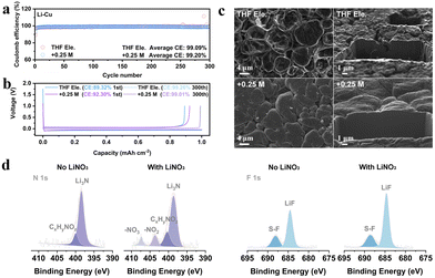
We choose the salt of LiNO3 since it has been well known as a powerful additive to stabilize Li anodes.25–27 In order to verify whether LiNO3 is equally applicable in THF based electrolyte, asymmetric Li||Cu electrochemical cells have been assembled to compare the Coulombic efficiencies (CEs) of lithium plating/stripping (Fig. 1a and Fig. S1, ESI†). The average CEs during 300 cycles of 1 M LiFSI in THF and 1 M LiFSI in THF with the addition of 0.25 M LiNO3, 0.5 M LiNO3, and 1 M LiNO3 are 99.09%, 99.20%, 99.01%, and 98.44%, respectively. The CE is higher than those of typical carbonate-based electrolytes with LiNO3 as an additive (≤98.5%, Table S1, ESI†). The corresponding Li plating/stripping curves of the four electrolytes are shown in Fig. 1b and Fig. S1b (ESI†). The initial CE increases from 89.32% to over 92% after adding LiNO3, suggesting the inhibited depletion of electrolyte attributed to the formation of the SEI. The morphology of lithium deposition is further observed by focused ion beam scanning electron microscopy (FIB-SEM) (Fig. 1c and Fig. S2, ESI†). Unlike conventional carbonate electrolytes that usually show wire-like Li morphology, all the deposited Li particles in THF-based electrolyte exhibit an irregular sphere like morphology with a micro-grade particle size, demonstrating the decent Li metal compatibility of ether electrolytes. In particular, the particles are smoother and more compact after introducing LiNO3, which can be visually observed from the cross-section of the deposited lithium. This phenomenon implies that the addition of NO3− effectively regulates the composition of the SEI layer and thus improves the uniformity of lithium metal deposition.
Therefore, X-ray photoelectron spectroscopy (XPS) was performed to analyse the characteristics of the SEI formed in THF electrolyte and +0.25 M LiNO3 electrolyte (Fig. 1d and Fig. S3, ESI†).28 Both THF and LiFSI have participated in the interfacial reaction and resulted in the formation of a hybrid organic and inorganic SEI, as typical peaks of C–O, O![[double bond, length as m-dash]](https://www.rsc.org/images/entities/char_e001.gif) C–O and CO32− in C 1s, and SO2F and Li2SO4 in S 2p can be detected in both electrolytes (Fig. S3, ESI†). The spectra of N 1s and F 1s in Fig. 1d show that large proportions of Li3N (398.9 eV) and LiF (684.8 eV) are generated at the anode interface, in which the signals of NO2− and NO3− for +0.25 M LiNO3 electrolyte prove that LiNO3 also contributes to the formation of SEI with the decomposition products of LixNyOz and Li2O (Fig. S3b, ESI†). Further quantitative evidence supporting these conclusions can also be found in Fig. S3e and f (ESI†). Overall, the addition of LiNO3 can intensify the stability of THF based electrolytes towards Li metal anodes, which encourages us to further explore its functions on the cathode side.
C–O and CO32− in C 1s, and SO2F and Li2SO4 in S 2p can be detected in both electrolytes (Fig. S3, ESI†). The spectra of N 1s and F 1s in Fig. 1d show that large proportions of Li3N (398.9 eV) and LiF (684.8 eV) are generated at the anode interface, in which the signals of NO2− and NO3− for +0.25 M LiNO3 electrolyte prove that LiNO3 also contributes to the formation of SEI with the decomposition products of LixNyOz and Li2O (Fig. S3b, ESI†). Further quantitative evidence supporting these conclusions can also be found in Fig. S3e and f (ESI†). Overall, the addition of LiNO3 can intensify the stability of THF based electrolytes towards Li metal anodes, which encourages us to further explore its functions on the cathode side.
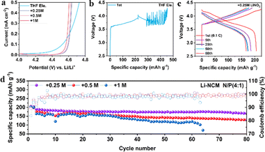
To verify whether LiNO3 can improve the oxidation stability of ether-based electrolytes, the electrochemical windows of the four electrolytes are tested by linear sweep voltammetry (LSV). As shown in Fig. 2a, all the electrolytes demonstrate oxidation stability over 4 V, enabling the operation of Li||LiFePO4 (LFP) batteries coupled with thin lithium (50 μm) and high capacity LFP (∼2.5 mA h cm−2) (Fig. S4, ESI†). Among them, +0.25 M LiNO3 electrolyte shows higher initial discharge specific capacity (154.5 mA h g−1) than +0.5 M or +1 M LiNO3 electrolyte (134.9 or 114.1 mA h g−1) and 97.4% capacity retention after 50 cycles. Intriguingly, the degradation potential of THF electrolyte is increased from lower than 4.2 V (vs. Li+/Li) to 4.5 V after the addition of LiNO3, which is further confirmed by Li (50 μm) ‖ high capacity NMC811 (∼3 mA h cm−2) batteries. The electrolyte of THF begins to undergo oxidative decomposition before charging to 4.2 V (Fig. 2b). In comparison, the electrolyte of +0.25 M LiNO3 shows a stable charge–discharge process (Fig. 2c), and the specific discharge capacity remains at 175 mA h g−1 after 50 cycles. Addition of more LiNO3 will lead to continuously increasing polarization potential and capacity decays (Fig. S5, ESI†). The long cycle tests of the Li||NMC811 battery demonstrate that both +0.25 M and +0.5 M LiNO3 electrolytes show an average CE over 99%, while +0.25 M LiNO3 electrolyte shows a higher capacity retention rate (167 mA h g−1vs. 130 mA h g−1) after 80 cycles (Fig. 2d). The electrolyte of +1 M LiNO3 shows the shortest cycling life among the three electrolytes, and the battery fails after 63 cycles. This result indicates that excessive LiNO3 may lead to immoderate interfacial reactions, accelerating the failure of the LMBs.
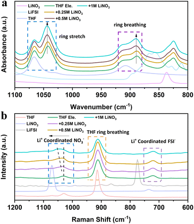
Interfacial and voltage stability are closely related to the solvation structures of electrolytes,29,30 which can be studied using Raman and infrared spectra. Attenuated total reflection-Fourier-transform infrared spectroscopy (ATR-FTIR) reveals multiple changes after adding LiFSI and LiNO3 into THF solvent (Fig. 3a). Firstly, both the ring breathing vibration peak located at 1068 cm−1 and the ring stretching vibration peak located at 910 cm−1 of THF split into two peaks after adding LiFSI.31 The new peak at a low wavenumber indicates the highly strained THF molecule with a changed shape due to the interaction with LiFSI. With the increase of LiNO3 content, the intensity of the new peak gradually increases, while the intensity of the free THF molecule decreases. These results indicate that the addition of NO3− strengthens the binding of THF molecules and further reduces the free solvent molecules in the bulk phase, thus promoting the oxidation resistance of the electrolyte. The strengthened binding of THF molecules is suggested to be caused by the electron deficiency on the N atom of LiNO3, introducing the interaction between THF molecules.32 The vibrations of the corresponding Raman spectra provide complementary evidence (Fig. 3b). When more LiNO3 is introduced into THF electrolytes, the Raman peak related to NO3− shifts from 1070 cm−1 to 1039 cm−1 and combines as one broad peak with THF molecules. The interaction between LiNO3 and THF also reduces the ionic conductivity of the electrolyte (Fig. S6, ESI†), which may be caused by the suppressed movement and the dissociation ability of THF molecules with addition of LiNO3. It is worth mentioning that THF is also a promising electrolyte for LMBs working under low temperatures. The ionic conductivity is higher than 2 mS cm−1 at −50 °C (Fig. S6, ESI†). The cumulative results of spectroscopy unveil that LiNO3 is able to change the structure and dynamics of THF molecules, which will further alter the interphase on both the Li metal anode and the high voltage cathode.
 | ||
| Fig. 3 Spectral characterizations of THF-based electrolyte: (a) ATR-FTIR and (b) Raman spectra of the designed electrolytes. Pure THF solvent, LiNO3 and LiFSI were also tested for comparison. | ||
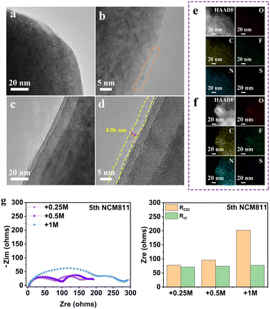
Taking THF electrolyte and +0.25 M LiNO3 electrolyte as examples, we first compared the morphology evolution of the NMC811 electrode after cycling by high-resolution transmission electron microscopy (HRTEM) (Fig. 4a–d). The surface of NMC811 particles after charging in THF electrolyte at high potential is covered by an incomplete CEI layer. In contrast, the presence of LiNO3 contributes to the formation of a uniform and thin CEI layer on the cathode surface of NMC811 after 5 cycles (Fig. 4c and d), which is believed to successfully inhibit the continuous degradation of the electrolyte. The corresponding EDS mapping of elements C, N, O, F and S also confirms the more homogeneous distribution and stronger signal for +0.25 LiNO3 electrolyte (Fig. 4e and f). The formation of a stable CEI is further verified by the electrochemical impedance spectra (EIS) of the Li||NMC811 battery (Fig. 4g). The batteries with all electrolytes demonstrate similar charge transfer resistance (Rct), but totally different interphase resistance (RCEI) values, which are 77.8 Ω (+0.25 M LiNO3), 96.1 Ω (+0.5 M LiNO3) and 201.9 Ω (+1 M LiNO3), respectively. This result demonstrates that a small amount of LiNO3 can form a thin CEI layer with fast dynamics, while excessive LiNO3 will increase the interfacial impedance and seriously slow down the Li-ion diffusion at the high-voltage cathode interface.
The effect of LiNO3 on the composition of the CEI on the NMC811 cathode surface is further studied by X-ray photoelectron spectroscopy (XPS) (Fig. S7, ESI†).4,28 Both organic and inorganic components such as C–H, C–O, C![[double bond, length as m-dash]](https://www.rsc.org/images/entities/char_e001.gif) O, and CO32− derived from the decomposition of THF, and LiF, Li3N, Li2O and Li2SO4 derived from the decomposition of lithium salts can be observed in the two electrolyte systems. In particular, the much higher CxHyNOz content in the N 1s spectrum of the THF electrolyte system is attributed to the significant depletion of both the THF solvent molecule and FSI− at the cathode interface. In comparison, the interface product is mainly Li3N for the +0.25 M LiNO3 electrolyte system, which suggests that the anion consumption contributes to the CEI layer. Meanwhile, LiF is also detected on the cathode surface of NMC811 in the system containing LiNO3. The highly uniform and integrated CEI with the combination of highly ion conductive Li3N and highly electron insulating LiF facilitates the ion-transport through the CEI and prevents electron tunneling,29 thereby preventing continued decomposition of the electrolyte.
O, and CO32− derived from the decomposition of THF, and LiF, Li3N, Li2O and Li2SO4 derived from the decomposition of lithium salts can be observed in the two electrolyte systems. In particular, the much higher CxHyNOz content in the N 1s spectrum of the THF electrolyte system is attributed to the significant depletion of both the THF solvent molecule and FSI− at the cathode interface. In comparison, the interface product is mainly Li3N for the +0.25 M LiNO3 electrolyte system, which suggests that the anion consumption contributes to the CEI layer. Meanwhile, LiF is also detected on the cathode surface of NMC811 in the system containing LiNO3. The highly uniform and integrated CEI with the combination of highly ion conductive Li3N and highly electron insulating LiF facilitates the ion-transport through the CEI and prevents electron tunneling,29 thereby preventing continued decomposition of the electrolyte.
In summary, we found that a small amount of NO3− in THF can not only enable an average CE of 99.20% for lithium plating/stripping, but also contribute to high-voltage stability. The capacity retention is 90% for practical Li||NMC811 batteries after 80 cycles. The high voltage stability of over 4.5 V is suggested to emerge from the regulation of the electrolyte solvation structure with the formation of a uniform CEI on the surface of the cathode. Considering the varieties of ether-based electrolytes, this work is anticipated to inspire more progress on developing cost-efficient electrolytes for energy-dense LMBs.
Conflicts of interest
There are no conflicts to declare.Acknowledgements
This work was supported by the National Key R&D Program of China (2021YFB2500300).Notes and references
- S. Mao, Q. Wu, F. Ma, Y. Zhao, T. Wu and Y. Lu, Chem. Commun., 2021, 57, 840–858 RSC.
- J. Liu, Z. Bao, Y. Cui, E. J. Dufek, J. B. Goodenough, P. Khalifah, Q. Li, B. Y. Liaw, P. Liu, A. Manthiram, Y. S. Meng, V. R. Subramanian, M. F. Toney, V. V. Viswanathan, M. S. Whittingham, J. Xiao, W. Xu, J. Yang, X.-Q. Yang and J.-G. Zhang, Nat. Energy, 2019, 4, 180–186 CrossRef CAS.
- M. Zhang, R. Liu, Z. Wang, X. Xing, Y. Liu, B. Deng and T. Yang, Chin. Chem. Lett., 2020, 31, 1217–1220 CrossRef CAS.
- Q. Zhao, N. W. Utomo, A. L. Kocen, S. Jin, Y. Deng, V. X. Zhu, S. Moganty, G. W. Coates and L. A. Archer, Angew. Chem., Int. Ed., 2022, 61, e202116214 CAS.
- J. Zheng, M. S. Kim, Z. Tu, S. Choudhury, T. Tang and L. A. Archer, Chem. Soc. Rev., 2020, 49, 2701–2750 RSC.
- B. Thirumalraj, T. T. Hagos, C. J. Huang, M. A. Teshager, J. H. Cheng, W. N. Su and B. J. Hwang, J. Am. Chem. Soc., 2019, 141, 18612–18623 CrossRef CAS PubMed.
- S. Zhang, S. Li and Y. Lu, eScience, 2021, 1, 163–177 CrossRef.
- W. Wang, X. Zhu and L. Fu, CCS Chem., 2021, 3, 686–695 CrossRef CAS.
- T. Zhou, Y. Zhao, M. El Kazzi, J. W. Choi and A. Coskun, Angew. Chem., Int. Ed., 2022, 61, e202115884 CAS.
- M. Li, C. Wang, Z. Chen, K. Xu and J. Lu, Chem. Rev., 2020, 120, 6783–6819 CrossRef CAS PubMed.
- X. B. Cheng, R. Zhang, C. Z. Zhao and Q. Zhang, Chem. Rev., 2017, 117, 10403–10473 CrossRef CAS PubMed.
- V. R. K. a J. H. Young, Science, 1979, 204, 499–501 CrossRef PubMed.
- Y.-B. Niu, Y.-X. Yin, W.-P. Wang, P.-F. Wang, W. Ling, Y. Xiao and Y.-G. Guo, CCS Chem., 2020, 2, 589–597 CrossRef CAS.
- L. Tan, S. Chen, Y. Chen, J. Fan, D. Ruan, Q. Nian, L. Chen, S. Jiao and X. Ren, Angew. Chem., Int. Ed., 2022, 61, e202203693 CAS.
- X. Fan and C. Wang, Chem. Soc. Rev., 2021, 50, 10486–10566 RSC.
- X. Zheng, L. Huang, X. Ye, J. Zhang, F. Min, W. Luo and Y. Huang, Chemistry, 2021, 7, 2312–2346 CrossRef CAS.
- Y. Chen, Z. Yu, P. Rudnicki, H. Gong, Z. Huang, S. C. Kim, J. C. Lai, X. Kong, J. Qin, Y. Cui and Z. Bao, J. Am. Chem. Soc., 2021, 143, 18703–18713 CrossRef CAS PubMed.
- Q. Li, J. Zhang, Y. Zeng, Z. Tang, D. Sun, Z. Peng, Y. Tang and H. Wang, Chem. Commun., 2022, 58, 2597–2611 RSC.
- T. D. Pham, A. Bin Faheem, J. Kim, H. M. Oh and K. K. Lee, Small, 2022, 18, e2107492 CrossRef PubMed.
- T. D. Pham, A. Bin Faheem and K. K. Lee, Small, 2021, 17, e2103375 CrossRef PubMed.
- X. Peng, Y. Lin, Y. Wang, Y. Li and T. Zhao, Nano Energy, 2022, 96, 107102 CrossRef CAS.
- Y. Jie, X. Ren, R. Cao, W. Cai and S. Jiao, Adv. Funct. Mater., 2020, 30, 1910777 CrossRef CAS.
- N. Xu, J. Shi, G. Liu, X. Yang, J. Zheng, Z. Zhang and Y. Yang, J. Power Sources, 2021, 7, 100043 CrossRef CAS.
- H. Wang, Z. Yu, X. Kong, W. Huang, Z. Zhang, D. G. Mackanic, X. Huang, J. Qin, Z. Bao and Y. Cui, Adv. Mater., 2021, 33, e2008619 CrossRef PubMed.
- X. Li, R. Zhao, Y. Fu and A. Manthiram, eScience, 2021, 1, 108–123 CrossRef.
- Z. Zhang, J. Wang, S. Zhang, H. Ying, Z. Zhuang, F. Ma, P. Huang, T. Yang, G. Han and W.-Q. Han, Energy Storage Mater., 2021, 43, 229–237 CrossRef.
- L. P. Hou, N. Yao, J. Xie, P. Shi, S. Y. Sun, C. B. Jin, C. M. Chen, Q. B. Liu, B. Q. Li, X. Q. Zhang and Q. Zhang, Angew. Chem., Int. Ed., 2022, 61, e202201406 CAS.
- D. Aurbach, E. Pollak, R. Elazari, G. Salitra, C. S. Kelley and J. Affinito, J. Electrochem. Soc., 2009, 156, A694 CrossRef CAS.
- W. Zhang, Y. Lu, L. Wan, P. Zhou, Y. Xia, S. Yan, X. Chen, H. Zhou, H. Dong and K. Liu, Nat. Commun., 2022, 13, 2029 CrossRef CAS PubMed.
- H. Wang, J. Zhang, H. Zhang, W. Li, M. Chen, Q. Guo, K. C. Lau, L. Zeng, G. Feng, D. Zhai and F. Kang, Cell Rep. Phys. Sci., 2022, 3, 100919 CrossRef CAS.
- H. F. Shurvell and M. C. Southby, Vib. Spectrosc., 1997, 15, 137–146 CrossRef CAS.
- Q. Zhao, X. Liu, J. Zheng, Y. Deng, A. Warren, Q. Zhang and L. Archer, Proc. Natl. Acad. Sci. U. S. A., 2020, 117, 26053–26060 CrossRef CAS PubMed.
Footnote |
| † Electronic supplementary information (ESI) available. See DOI: https://doi.org/10.1039/d2ya00252c |
| This journal is © The Royal Society of Chemistry 2022 |


