 Open Access Article
Incorporation of fillers to modify the mechanical performance of inverse vulcanised polymers†
Veronica
Hanna
,
Peiyao
Yan
,
Samuel
Petcher
and
Tom
Hasell
 *
*
Department of Chemistry, University of Liverpool, Crown Street, Liverpool, L69 7ZD, UK. E-mail: t.hasell@liverpool.ac.uk
First published on 20th June 2022
Abstract
Sulfur is a by-product of the refinement of crude oil and natural gas, produced at millions of tonnes per annum, resulting in large overground storage of elemental sulfur. “Inverse vulcanisation” allows for the use of high proportions of sulfur to synthesise inverse vulcanised polymers. However, inverse vulcanised polymers need to be further improved in their mechanical performance to widen their applications. Like with many conventional polymers, fillers can also be used to tailor the mechanical properties of inverse vulcanised polymers, for example, by increasing their tensile strength. The use of the polymer, sulfur-1,3-diispropenylbenzene (S-DIB), as a model system for the addition of fillers (carbon black, cellulose microfibres, and nanoclay) at 2–10 wt% (weight percentage) and their effect on the mechanical properties of the resultant composite is reported herein. Following optimisation with S-DIB, the technique was shown to be transferable to related polymer systems.
Introduction
Inverse vulcanised polymers, also known as sulfur polymers, allow for the utilization of >50 wt% (weight percentage) elemental sulfur, using the process “inverse vulcanisation” as coined by Pyun et al.1 Sulfur is a by-product of the refinement of crude oil and natural gas, produced at over 70 million tonnes per annum.2,3 Some of the current applications of sulfur include vulcanisation of rubber,4 fertilisers,5 and the production of sulfuric acid;6 however, there remains a large sulfur surplus.7Generally, the synthesis of inverse vulcanised polymers first involves the melting of elemental sulfur above its floor temperature of 159 °C to initiate ring opening polymerisation (ROP). This produces diradical polysulfide chains which are unstable and can return to the cyclic S8 structure of elemental sulfur. To prevent this, inverse vulcanisation is carried out by employing vinyl crosslinkers (Scheme 1a). The C![[double bond, length as m-dash]](https://www.rsc.org/images/entities/char_e001.gif) C double bonds present in crosslinkers react with the terminal sulfur radicals to stabilise the polysulfide chains. This ability to crosslink and stabilise polysulfide chains allows for the high sulfur content observed in inverse vulcanised polymers.1,7
C double bonds present in crosslinkers react with the terminal sulfur radicals to stabilise the polysulfide chains. This ability to crosslink and stabilise polysulfide chains allows for the high sulfur content observed in inverse vulcanised polymers.1,7
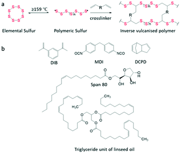 | ||
| Scheme 1 (a) Reaction scheme of inverse vulcanisation. (b) Structure of monomers used in this study. | ||
The applications of inverse vulcanised polymers include heavy metal capture,8,9 Li–S batteries,10 oil–water separation,11 IR transparent lenses,12 self-healing materials,13 and construction materials.14,15 The low cost of sulfur, and many of the crosslinkers used, as well as the simplicity of the synthesis which is often solvent-less and one pot, gives inverse vulcanisation the potential to produce materials economically at scale.16 Inverse vulcanised polymers have also been reported to be recyclable owing to the reversibility of the S–S bond, classifying them as vitrimers.3,17,18 This ability to be re-processed opens doors to further physical property enhancements post-synthesis.19
Although inverse vulcanised polymers currently have these useful applications, many of them do not possess suitable mechanical properties to be put to practical use. Currently, the benchmark in tensile strength for inverse vulcanised polymers is 60.44 MPa for a polymer with allyl glycidyl ether (AGE), reported by Char et al.20 However, many inverse vulcanised polymers attain tensile strengths lower than conventional polymers, such as polyurethane (24 MPa), polypropylene (26 MPa), and polystyrene (34 MPa).21 The softer inverse vulcanised polymers tend to be weak, such as S-canola oil, while stiffer, stronger inverse vulcanised polymers such as S-dicyclopentadiene (S-DCPD) tend to be highly brittle.22 Stronger inverse vulcanised polymers are usually not ductile, limiting their toughness, which is determined by the area under the curve (AUC) in stress–strain graphs.22 Currently a lot of research has been focused on tailoring the properties of inverse vulcanised polymers by changing the crosslinker and wt% of sulfur,22–24 or including secondary crosslinking functionalities.17,20,25 An alternative method to modify inverse vulcanised polymers is by the addition of fillers.
Fillers are most often solid particulate additives that can be added to enhance the properties or to lower the cost of the polymer.26 Many conventional polymers use fillers for enhancement, such as polypropylene using calcium carbonate for increased toughness.27 Elastomers such as rubber are often filled with carbon black (CB) and silica; car tires greatly benefit from the abrasion resistance and decreased heat build-up provided by silica, improving their durability.28 Another example is glass-fibre-reinforced polyester, used in a wide range of applications in cars, ships and aircrafts, whereas, the brittleness and low strength of unfilled polyester has more limited applications.29 It can be established that without fillers, some polymers would fail to meet the specifications required for their current applications.4 Therefore, investigating the use of fillers to apply to different inverse vulcanised polymers allows for a further increase in the versatility of the properties that can be achieved.
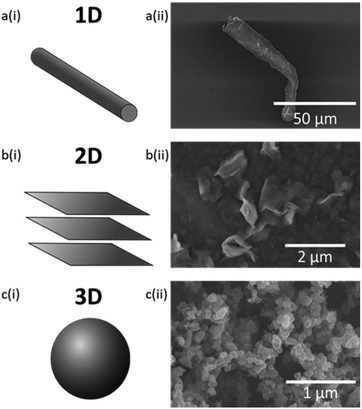
For conventional polymers, it is generally understood that the properties obtained are predominantly determined by the size and geometry of the filler particle. Filler particle geometry is classed as 1D for fibres, 2D for flat, layered structures, and 3D for spherical and ellipsoidal particles (Fig. 1).26 Studies have shown that fillers of increasing aspect ratio stiffen the polymer. Therefore, it was expected that fillers with a fibre geometry would result in the greatest increase in the stiffness of the polymer.30 However, particle size also has a large effect, where smaller particles provide a larger surface area; therefore, greater interfacial area for adhesion between filler and polymer.31
Unlike conventional carbon-based polymers, there have not been many studies on the modification of inverse vulcanised polymers using fillers. Zhang et al. reported the use of liquid metals: gallium, gallium–zinc eutectic alloy, and gallium–indium eutectic alloy in sulfur-1,3-diispropenylbenzene (S-DIB). The addition of these liquid fillers provided an increase in tensile strength and conductivity in the polymers. The addition of liquid metals at 20.95 wt% resulted in an increase in tensile strength from 0.25 MPa to 0.59 MPa.18 Chalker et al. studied the reinforcing properties of wool that was stretched and aligned in different orientations.32 Ryu et al. used ZnS to increase the refractive index and improve the thermomechanical properties of inverse vulcanised polymers for applications such as optical lenses.33 Liu et al. used several solid fillers to investigate their ability to adjust polymer density.34 Many other reported uses of fillers in inverse vulcanised polymers have been for Li–S battery applications, for example, the addition of molybdenum disulfide (MoS2) to S-DIB at loadings of 10–50 wt% by Pyun et al.35,36 Most literature have not reported the effect of the fillers on the mechanical properties of the inverse vulcanised polymers. Only Chalker et al. and Zhang et al. have reported effects on mechanical properties such as tensile strength. However, composites containing wool cannot be reprocessed without affecting the alignment of the wool fibres.32 Also, liquid metals are more unconventional fillers, resulting in a gap in the research on more common solid fillers and their effect on the mechanical properties of inverse vulcanised polymers.18,26 Here, we report the first study on how the addition of solid particulate fillers modify physical properties, such as tensile strength, of inverse vulcanised polymers.
Experimental
Materials
Sulfur (S8, 325 mesh, ≥99.5%, Brenntag UK & Ireland), 1,3-diisopropenylbenzene (DIB, Tokyo Chemical industry), dicyclopentadiene (DCPD, Tokyo Chemical industry), 4,4′-methylenebis(phenyl isocyanate) (MDI, 98%, Sigma-Aldrich), Span 80 (Span, Sigma-Aldrich), linseed oil (LO, Sigma-Aldrich), carbon black (CB, acetylene, 50% compressed, 99.9+%, Sigma-Aldrich), nanoclay hydrophilic bentonite (NC, Sigma-Aldrich), and microfibres filler powder (CMF, MBFibreglass). All chemicals were used without further purification.Characterisation
Tensile tests were carried out using Shimadzu EZ Test at a crosshead speed of 5 mm min−1 at 25 °C.Differential scanning calorimetry (DSC) thermograms were obtained using TA DSC25, where heat-cool-heat cycles were carried out with temperature ranges of −50–150 °C, and −50–60 °C under nitrogen. The heating rate was 10 °C min−1 and the cooling rate was 5 °C min−1.
Fourier transform infrared spectroscopy (FT-IR) was performed with a Bruker Vertex V70 FT-IR spectrometer, with a germanium ATR crystal. Polymers and polymer composites were analysed as thin films with a thickness of ∼0.1 mm.
Scanning electron microscopy (SEM) imaging of the polymer and composite materials morphology was achieved using a Hitachi S-4800 cold Field Emission Scanning Electron Microscope (FE-SEM) operating in both scanning and transmission modes. The dry samples were prepared by adhering the polymer monoliths to a SEM stub with silver paint. Samples were coated with chromium by a Quorum sputter coater. Neat fillers were dispersed in methanol, then a drop of filler dispersion was placed on a plasma cleaned silica wafer to adhere to the surface. Only NC was sonicated in methanol for 15 min to allow for some exfoliation. Imaging was conducted at a working distance of ∼8 mm of 5 kV. Images were taken using a combination of both upper and lower detector signals.
Thermogravimetric analysis (TGA) was carried out using TA Instruments Discovery TGA550 with wire wound (Pt/Rh) furnace at a ramp rate of 10 °C min−1 to 600 °C under nitrogen purge gas.
Notation
The wt% of sulfur precedes the polymer name, and the wt% of the filler precedes their abbreviation. For example, for a 65 wt% S containing polymer, crosslinked with DIB, that has then been filled with carbon black to make up 2 wt% of the total composition, the notation would be: 65S-DIB-2CB. The 65 wt% sulfur, 35 wt% DIB designation therefore refers to the composition of the pure copolymer, before addition of filler.Synthesis of S-DIB
Sulfur (6.5 g, 0.20 mol) and DIB (3.5 g 0.022 mol) were added to a 40 mL reaction vial, sealed with a septum, and heated at 155 °C in a heating block on a hot plate with stirring at 900 rpm. The mixture changed from yellow to a dark red viscous mixture after 30 min and was poured out into a silicone mould. The polymer was placed into the oven to cure at 140 °C for 30 min.Synthesis of S-DCPD-LO
Sulfur (5 g, 0.16 mol), and linseed oil (LO) (2.5 g, 0.0089 mol) were added to 40 mL reaction vial and heated to 160 °C in a heating block on a hot plate with stirring at 900 rpm. After 1 h, pre-heated DCPD (2.5 g, 0.019 mol) was added to the viscous brown mixture. After 5–10 min, the polymer turned black and was poured into a silicone mould then cured in the oven at 140 °C for 3 h.Synthesis of S-Span-MDI
Sulfur (5 g, 0.16 mol), Span 80 (5 g, 0.0117 mol), and Zinc diethyldithiocarbamate (100 mg) were added to a 40 mL reaction vial and heated to 160 °C in a heating block on a hot plate with stirring at 900 rpm for ∼1 h. MDI (1.46 g, 0.00585 mol) was added to the light brown mixture and stirred for 3–5 min until viscosity increased. The mixture was poured into a silicone mould then placed in the oven to cure at 140 °C for ∼24 h.Synthesis of polymer composites
65S-DIB was frozen with liquid nitrogen and ground into a fine powder with a pestle and mortar. The chosen filler was added to the 65S-DIB polymer powder and mixed in using the aid of acetone. The powder polymer–filler mixture was hot-pressed at 120 °C for 10 min into a film with a thickness of ∼0.5 mm. The same process was carried out for S-DCPD-LO and S-Span-MDI, however, the polymer composite was cured for a further 2 h before hot-pressing a second time to make dog bones.Results and discussion
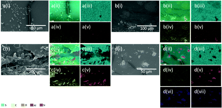
The fillers used in this study were CB, cellulose microfibres (CMF), and nanoclay (NC). Firstly, a flexible form of S-DIB was synthesised and characterised by FTIR, DSC, and TGA (available in the ESI†), then each filler was tested at loadings of 2–10 wt%. The reinforcing properties of the fillers being investigated were solely of interest, therefore there was more freedom with choosing the polymer system for the testing of the fillers. This meant that the strength of the polymer was insignificant, as long as the polymer matrix was flexible enough to undergo tensile testing with ease. Only the difference in strength between the chosen polymer for this study and the resultant polymer composite was of significance. There was no intention in achieving a polymer composite stronger than other reported inverse vulcanised polymers. S-DIB was chosen as the model system as it was tailored to be highly flexible; therefore, it simplified the process of cutting and tensile testing of dog bone samples by preventing breakage. When synthesised as reported in literature, S-DIB is usually brittle with a Tg above room temperature (43.5–49.2 °C).13 S-DIB could be tailored by shortening the curing time to afford a more flexible polymer with a Tg of −1.1 °C (Table S1†). A reaction temperature of 155 °C, close to the floor temperature of sulfur, slowed down the reaction to allow for more control.Sulfur polymer composites were prepared using a solid-grinding method post-synthesis of S-DIB using liquid nitrogen to make the polymer brittle and to prevent the polymer powder (Fig. 2b) from sticking together. Acetone was used to aid the mixing of the polymer powder by preventing electrostatic interactions. Using this method resulted in aggregation and agglomeration of fillers, as shown in Fig. 3. Addition of filler during polymer synthesis was unsuccessful, resulting in a significant increase in viscosity, while potentially interfering with the inverse vulcanisation reaction. Therefore, this method further limits the filler loading compared to the solid-grinding method. Higher loadings prevented stirring of the mixture or even reached saturation, resulting in solidification of the polymer mixture. Interference with the reaction itself put the polymer at a greater risk of depolymerisation, especially as it had a low curing time of 30 min.
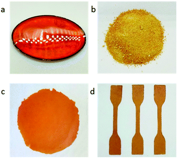 | ||
| Fig. 2 (a) S-DIB after curing in silicone mould (7.5 cm × 5.5 cm); (b) S-DIB in powder form; (c) S-DIB film; (d) dog bone samples of S-DIB (75 mm × 4 mm, with a gauge length of 25 mm). | ||
Aggregate formation of neat CB, and NC fillers are shown in Fig. 1cii and Fig. S12b,† respectively. In Fig. 3di, the morphology of NC particles in S-DIB-10NC is consistent with the micrograph of neat NC filler. EDS mapping confirms the presence of NC aggregates, with areas of very low sulfur concentration in Fig. 3d. The large aggregates formed by NC are likely due to its smaller particle size, strengthening filler–filler interactions significantly, preventing its even dispersion within the polymer matrix.37 Additionally, inverse vulcanised polymers are often found to be hydrophobic, whereas, NC is a hydrophilic filler.19,38 This further increases the difficulty in dispersing the NC particles.
The rough surface texture as seen in Fig. 3ci, as well as the increased C atom concentration (Fig. 3civ), indicates areas of higher concentration of CB. Whereas S-DIB morphology is mostly smooth with only the presence of sulfur crystals and stress lines from fracture. Although CB primary particles are spherical, with the lowest aspect ratio, the primary particles do not exist on their own, but instead are present within a branched aggregate structure (Fig. 1cii).4Fig. 3c indicates more of an agglomerate structure of the smaller aggregates of CB as there appears to be interactions with the polymer matrix within the agglomerate of CB. This is supported by EDS, showing the presence of sulfur atoms in the areas of the CB agglomerates, unlike the absence of S atoms at NC aggregate sites. If the whole structure was an aggregate made up of strongly interacting CB particles, interactions with the polymer matrix would likely be limited to only the surface of the aggregate. Instead, what can be observed in Fig. 3c is likely to be multiple small CB aggregates loosely bound together by van der Waals forces to make a larger agglomerate structure, hence, the successful stress transfer from polymer to filler achieved with CB in S-DIB.38 Also, CB is highly hydrophobic with good compatibility with most conventional polymers making it considered as a “universal filler”.31 This meant that stronger interfacial adhesion between CB and S-DIB was likely, indicating that CB was expected to be a more suitable filler than NC, with greater compatibility with S-DIB, which is also hydrophobic.19
CMF have a larger particle size than NC and CB, as a fibre is shown with a width of approximately 10–17 μm and length of approximately 75 μm in Fig. 1aii. However, its fibrous structure means that CMF tend to entangle, with high susceptibility to aggregation due to its hydrophilic nature.39 Although this is the case, their high aspect ratio is highly effective at reinforcing the polymer, often resulting in an increase in tensile strength.
As the fillers were not treated with coupling agents, strong covalent bonds between polymer and filler were not expected. To demonstrate this, DSC was carried out to reveal any significant changes in Tg with addition of fillers to indicate the type of polymer–filler interactions present. For most S-DIB composites, a decrease in Tg is observed, however for S-DIB-2NC, and S-DIB-10NC, an increase in Tg has occurred. As a significant increase in Tg has not been observed for most S-DIB composites, physical interactions (van der Waals) are likely to be the polymer–filler interactions present in the S-DIB composite samples.
Fillers, CB, CMF, and NC were tensile tested at loadings of 2 wt%–10 wt%. Each filler provided the greatest increase in tensile strength at 10 wt% loading, shown in Fig. 4, with CB providing the greatest increase in tensile strength overall (0.87 ± 0.0056 MPa), followed by CMF (0.82 ± 0.0092 MPa), then NC (0.55 ± 0.015 MPa). S-DIB-CB composite tensile strength increased with filler loading, whilst strain more gradually decreased. As a result of the maintained moderate ductility of S-DIB-CB composites at higher loadings, the toughness also increased.
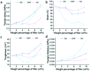 | ||
| Fig. 4 Graphs demonstrating the effect of loading S-DIB with different wt% of filler on (a) tensile stress; (b) strain; (c) toughness; (d) Young's modulus. | ||
As CMF loading increases, the tensile strength steeply increases, along with the Young's modulus, indicating an increase in stiffness. Although providing the second greatest increase in tensile strength at 10 wt% loading, CMF has caused a general decrease in toughness. As the high aspect ratio of CMF stiffens the polymer greatly, as confirmed by the Young's modulus, this becomes detrimental to the ductility of the polymer. The steep decrease in strain with increased CMF loading results in a strain of 42.16 ± 4.01% at 10 wt% – less than 50% of the strain attained by the pure polymer. The increase in aspect ratio increases anisotropy which results in the magnitude of tensile stress experienced being highly dependent on the orientation of the fibre. A fibre oriented parallel to the direction of the uniaxial tensile force attains a greater tensile strength than a fibre oriented perpendicular to the direction of the force. Although this is the case, the random orientations of the fibres likely eliminated the expected disparity between samples.
In contrast, as NC loading increases, the tensile strength of S-DIB more gradually increases. Loadings below 10 wt% did not increase tensile strength greatly, with some attaining lower tensile strengths than pure S-DIB. As NC is a mineral filler of higher density, a higher wt% is likely required to bring about a similar increase in tensile strength to lower density fillers such as CB and CMF. Although this was the case, S-DIB-NC polymer composites maintained the strain close to that of the pure polymer even at higher loadings. As the S-DIB-NC polymer composites remained ductile, only a small increase in tensile strength was required to increase the toughness. Hence, a loading of 10 wt% NC allowed for a significant increase in toughness although the tensile strength had not increased greatly compared to the other fillers.
As the highest increase in tensile strength was seen at 10 wt% for each filler, tests were repeated at this loading on other polymer systems. The polymer systems chosen were S-dicyclopentadiene-linseed oil (S-DCPD-LO) and S-Span 80-4,4′-methylenebis(phenyl isocyanate) (S-Span-MDI). 50S-DCPD-LO, contains an equal ratio of LO to DCPD to exploit the flexibility provided by the long-chain triglyceride structure in LO to counteract the brittleness usually provided by crosslinking with DCPD.22 Like LO, Span provides flexibility to 50S-Span-MDI. Span first reacts with sulfur to form a linear pre-polymer consisting of long sulfur-based chains, followed by crosslinking of the hydroxide groups on Span with MDI to form urethane bonds.17 The mole ratio of Span to MDI used was chosen based on which polymer would be considerably stronger than S-DCPD-LO whilst also providing enough flexibility, ideal for tensile testing. As both are terpolymers, they are more complex polymer systems compared to S-DIB. Further optimisation of the synthesis was required for S-DCPD-LO and S-Span-MDI to properly incorporate the filler, ensuring strong enough polymer–filler interactions for stress transfer to be feasible. After hot-pressing the S-DCPD-LO–filler mixture, the sample was placed into the oven to cure for a further 2 h, followed by hot-pressing and cutting into dog bones. This additional re-curing step was necessary for the filler to be able to reinforce these polymers through stress-transfer. Without re-curing, the polymer composites were achieving very similar tensile strengths to the pure polymer, but with a lower strain, decreasing the toughness of the polymers (Fig. S7b†).
Fig. 5 shows the effect of re-curing on S-DCPD-LO-10CB. Although the re-cured sample also contains large agglomerates, the concentration of CB particles within the agglomerate appears to be significantly reduced. This could indicate a greater interaction between CB and the polymer matrix. Fig. 5aii of the micrograph of re-cured S-DCPD-LO-10CB sample appears to contain fewer pores, hence fewer defects within the sample that can have a significant impact on the tensile test.
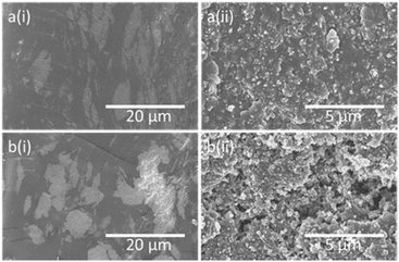 | ||
| Fig. 5 (a) Micrographs of the cross-section of S-DCPD-LO-10CB sample that was both hot-pressed and re-cured. (b) Micrographs of the cross-section of S-DCPD-LO-10CB sample that was only hot-pressed. | ||
The 30 min curing time meant that S-DIB was only partially crosslinked, making it easier to process. This meant S-DIB did not require the additional recuring step for sufficient polymer–filler interactions, making it more ideal as the model system. As the hot-pressing conditions were capable of curing S-DIB, confirmed by an increase in Tg (Table S1†), the curing process might be responsible for the formation of polymer–filler interactions, hence the change in conditions was necessary to provide curing conditions for S-DCPD-LO and S-Span-MDI to incorporate the filler particles more effectively. As S-DCPD-LO and S-Span-MDI were both cured for a longer time than S-DIB any further changes in the structure through re-curing could be slower compared to S-DIB. This could be due to both S-DCPD-LO and S-Span-MDI possessing higher crosslinking densities than S-DIB, hence requiring a greater length of time for chain movement upon heating within a more restrictive polymer matrix.
Mostly similar observations were made for all fillers in S-DCPD-LO and S-Span-MDI polymers. CB and CMF remained closely matched in their effect on tensile strength, providing a similar percentage increase of ∼78% in S-Span-MDI (Fig. 6). Unlike S-DIB and S-DCPD-LO, S-Span-MDI toughness decreased with the addition of fillers at 10 wt% loading. The addition of CB to S-DCPD-LO and S-Span-MDI attained the greatest increase in Young's Modulus. This explains the decrease in toughness when 10 wt% CB is added to S-Span-MDI as S-Span-MDI-10CB achieved the lowest strain. These results confirm that the fillers in this study have the potential to be applied to a variety of inverse vulcanised polymers.
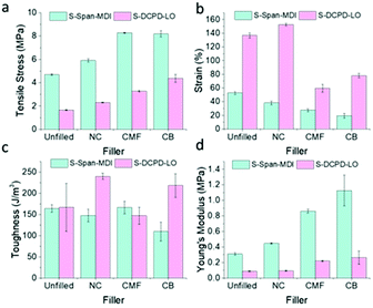 | ||
| Fig. 6 Bar charts demonstrating the effect of loading S-DCPD-LO and S-Span-MDI with different wt% of filler on (a) tensile stress; (b) strain; (c) toughness; (d) Young's modulus. | ||
As the maximum filler loading was limited to 10 wt%, limitations to the extent of mechanical modifications on the polymer systems therefore resulted. As indicated by the trend in increasing tensile strength with filler loading, higher loadings than 10 wt% have the potential to further increase the tensile strength of inverse vulcanised polymers, provided they are homogeneously mixed to prevent formation of any large aggregates.
Conclusions
The fillers investigated have demonstrated that a variety of property modifications can be achieved when added to inverse vulcanised polymers. All fillers provided the greatest increase in tensile stress at 10 wt% loading, also resulting in an increase in toughness of S-DIB when filled with CB or NC. Only a 10 wt% loading of fillers in S-DIB was required to achieve a 129% increase in tensile strength (CB), 93% increase in toughness (NC), and 634% increase in Young's modulus (CMF). Similar trends in results have been observed for NC and CMF in S-DIB, S-DCPD-LO, and S-Span-MDI, with the exception of CB increasing Young's modulus more greatly than CMF in S-DCPD-LO than in S-DIB.Deviations in the properties provided by the fillers from what was expected by their particle geometry owes to particle aggregation. This phenomenon is more apparent in smaller particle sized fillers, CB, and NC. Usage of filler loadings greater than 10 wt% were not carried out as processing difficulties can potentially arise, as well as the increased difficulty of cutting dog bone samples containing higher filler loadings. Low density fillers, such as CB, also appeared to be very close to, or reached saturation point at 10 wt%, with a small excess of CB that had not been hot-pressed into the polymer. This limited the mechanical property enhancements that could be achieved. Higher density fillers would have the ability to easily be added at higher loadings, such as MoS2, reported at loadings of up to 50 wt%.36
Attaining strong enough polymer–filler interactions for stress-transfer can be more difficult in some inverse vulcanised polymers compared to others depending on ease of processing. This was demonstrated with S-DCPD-LO and S-Span-MDI, both requiring an extra re-curing step after incorporation of the fillers.
As the dispersion of fillers were not optimal and the loading was low, more advanced processing techniques, such as screw extrusion, and/or compatibilising agents may allow for more homogeneous mixing, higher levels of filler loading, and therefore even greater enhancements of properties. These results therefore show excellent potential for future work.
Conflicts of interest
There are no conflicts to declare.Acknowledgements
We thank Owen Gallagher and Keith Arnold for SEM assistance, and Krzysztof Pawlak for FT-IR assistance. We also acknowledge Romy Dop for helpful discussions on SEM, and Joseph Dale and Becky Chadwick for useful discussions. T. H. is supported by a Royal Society University Research Fellowship.Notes and references
- W. Chung, J. Griebel, E. Kim, H. Yoon, A. Simmonds, H. Ji, P. Dirlam, R. Glass, J. J. Wie, N. Nguyen, B. Guralnick, J. Park, A. Somogyi, P. Theato, M. Mackay, Y.-E. Sung, K. Char and J. Pyun, Nat. Chem., 2013, 5, 518–524 CrossRef CAS PubMed.
- A.-M. O. Mohamed and M. El-Gamal, Sulfur concrete for the construction industry: a sustainable development approach, J. Ross Publishing, 2010 Search PubMed.
- T. Lee, P. T. Dirlam, J. T. Njardarson, R. S. Glass and J. Pyun, J. Am. Chem. Soc., 2022, 144, 5–22 CrossRef CAS PubMed.
- J. E. Mark, B. Erman and M. Roland, The science and technology of rubber, Academic press, 2013 Search PubMed.
- D. Messick, M. Fan and C. De Brey, Sulphur Sources, their Processing and Use in Fertiliser Manufacture, IFS, 2002 Search PubMed.
- M. King, M. Moats and W. G. Davenport, Sulfuric acid manufacture: analysis, control and optimization, Newnes, 2013 Search PubMed.
- X. Jiang, Sulfur Chemistry, Springer Nature, 2019 Search PubMed.
- M. P. Crockett, A. M. Evans, M. J. H. Worthington, I. S. Albuquerque, A. D. Slattery, C. T. Gibson, J. A. Campbell, D. A. Lewis, G. J. L. Bernardes and J. M. Chalker, Angew. Chem., Int. Ed., 2016, 55, 1714–1718 CrossRef CAS PubMed.
- M. J. H. Worthington, R. L. Kucera, I. S. Albuquerque, C. T. Gibson, A. Sibley, A. D. Slattery, J. A. Campbell, S. F. K. Alboaiji, K. A. Muller, J. Young, N. Adamson, J. R. Gascooke, D. Jampaiah, Y. M. Sabri, S. K. Bhargava, S. J. Ippolito, D. A. Lewis, J. S. Quinton, A. V. Ellis, A. Johs, G. J. L. Bernardes and J. M. Chalker, Chem. – Eur. J., 2017, 23, 16219–16230 CrossRef CAS PubMed.
- I. Gomez, D. Mecerreyes, J. A. Blazquez, O. Leonet, H. Ben Youcef, C. Li, J. L. Gómez-Cámer, O. Bondarchuk and L. Rodriguez-Martinez, J. Power Sources, 2016, 329, 72–78 CrossRef CAS.
- M. J. H. Worthington, C. J. Shearer, L. J. Esdaile, J. A. Campbell, C. T. Gibson, S. K. Legg, Y. Yin, N. A. Lundquist, J. R. Gascooke, I. S. Albuquerque, J. G. Shapter, G. G. Andersson, D. A. Lewis, G. J. L. Bernardes and J. M. Chalker, Adv. Sustainable Syst., 2018, 2, 1800024 CrossRef.
- J. J. Griebel, S. Namnabat, E. T. Kim, R. Himmelhuber, D. H. Moronta, W. J. Chung, A. G. Simmonds, K.-J. Kim, J. van der Laan, N. A. Nguyen, E. L. Dereniak, M. E. Mackay, K. Char, R. S. Glass, R. A. Norwood and J. Pyun, Adv. Mater., 2014, 26, 3014–3018 CrossRef CAS PubMed.
- J. J. Griebel, N. A. Nguyen, S. Namnabat, L. E. Anderson, R. S. Glass, R. A. Norwood, M. E. Mackay, K. Char and J. Pyun, ACS Macro Lett., 2015, 4, 862–866 CrossRef CAS PubMed.
- M. K. Lauer, M. S. Karunarathna, A. G. Tennyson and R. C. Smith, Mater. Adv., 2020, 1, 2271–2278 RSC.
- M. S. Karunarathna, M. K. Lauer, T. Thiounn, R. C. Smith and A. G. Tennyson, J. Mater. Chem. A, 2019, 7, 15683–15690 RSC.
- D. J. Parker, H. A. Jones, S. Petcher, L. Cervini, J. M. Griffin, R. Akhtar and T. Hasell, J. Mater. Chem. A, 2017, 5, 11682–11692 RSC.
- P. Y. Yan, W. Zhao, B. W. Zhang, L. Jiang, S. Petcher, J. A. Smith, D. J. Parker, A. I. Cooper, J. X. Lei and T. Hasell, Angew. Chem., Int. Ed., 2020, 59, 13371–13378 CrossRef CAS PubMed.
- Y. M. Xin, H. Peng, J. Xu and J. Y. Zhang, Adv. Funct. Mater., 2019, 29, 7 CrossRef.
- A. H. Segej Diez, P. Theato and W. Pauer, MDPI, 2017, 9, 59 Search PubMed.
- S. Park, M. Chung, A. Lamprou, K. Seidel, S. Song, C. Schade, J. Lim and K. Char, Chem. Sci., 2022, 13, 566–572 RSC.
- T. R. Crompton, Physical testing of plastics, Smithers Rapra, 2012 Search PubMed.
- J. A. Smith, S. J. Green, S. Petcher, D. J. Parker, B. W. Zhang, M. J. H. Worthington, X. F. Wu, C. A. Kelly, T. Baker, C. T. Gibson, J. A. Campbell, D. A. Lewis, M. J. Jenkins, H. Willcock, J. M. Chalker and T. Hasell, Chem. – Eur. J., 2019, 25, 10433–10440 CrossRef CAS PubMed.
- J. A. Smith, X. F. Wu, N. G. Berry and T. Hasell, J. Polym. Sci., Part A: Polym. Chem., 2018, 56, 1777–1781 CrossRef CAS PubMed.
- X. F. Wu, J. A. Smith, S. Petcher, B. W. Zhang, D. J. Parker, J. M. Griffin and T. Hasell, Nat. Commun., 2019, 10, 9 CrossRef PubMed.
- P. Yan, W. Zhao, S. J. Tonkin, J. M. Chalker, T. L. Schiller and T. Hasell, Chem. Mater., 2022, 34, 1167–1178 CrossRef CAS.
- J. Murphy, Additives for Plastics Handbook, Elsevier Science, 2nd edn, 2001 Search PubMed.
- W. Zuiderduin, C. Westzaan, J. Huetink and R. Gaymans, Polymer, 2003, 44, 261–275 CrossRef CAS.
- S. Bhattacharyya, V. Lodha, S. Dasgupta, R. Mukhopadhyay, A. Guha, P. Sarkar, T. Saha and A. K. Bhowmick, J. Appl. Polym. Sci., 2019, 136, 47560 CrossRef.
- C. Varga, N. Miskolczi, L. Bartha and G. Lipóczi, Mater. Des., 2010, 31, 185–193 CrossRef CAS.
- J. C. Halpin and J. L. Kardos, J. Appl. Phys., 1972, 43, 2235–2241 CrossRef CAS.
- R. Rothon, Fillers for Polymer Applications, Springer, Cham, 2017 Search PubMed.
- I. B. Najmah, N. A. Lundquist, M. K. Stanfield, F. Stojcevski, J. A. Campbell, L. J. Esdaile, C. T. Gibson, D. A. Lewis, L. C. Henderson, T. Hasell and J. M. Chalker, ChemSusChem, 2021, 14, 2352–2359 CrossRef PubMed.
- M. D. Islam, S. P. Liu, D. A. Boyd, Y. X. Zhong, M. M. Nahid, R. Henry, L. Taussig, Y. Ko, V. Q. Nguyen, J. D. Myers, C. C. Baker, W. Kim, J. S. Sanghera, E. M. Smith, J. S. Derov, X. C. Ye, A. Amassian, H. Ade, J. Genzer and J. E. Ryu, Opt. Mater., 2020, 108, 10 CrossRef.
- Y. X. Liu, Y. D. Chen, Y. G. Zhang, Y. R. Chen, L. L. Wang, X. J. Zan and L. T. Zhang, Polymer, 2020, 12, 15 Search PubMed.
- P. T. Dirlam, R. S. Glass, K. Char and J. Pyun, J. Polym. Sci., Part A: Polym. Chem., 2017, 55, 1635–1668 CrossRef CAS.
- P. T. Dirlam, J. Park, A. G. Simmonds, K. Domanik, C. B. Arrington, J. L. Schaefer, V. P. Oleshko, T. S. Kleine, K. Char, R. S. Glass, C. L. Soles, C. Kim, N. Pinna, Y.-E. Sung and J. Pyun, ACS Appl. Mater. Interfaces, 2016, 8, 13437–13448 CrossRef CAS PubMed.
- B. Pukánszky and E. Fekete, Period. Polytech., Chem. Eng., 1998, 42, 167–187 Search PubMed.
- J. Fröhlich, W. Niedermeier and H.-D. Luginsland, Composites, Part A, 2005, 36, 449–460 CrossRef.
- J. Lu, P. Askeland and L. T. Drzal, Polymer, 2008, 49, 1285–1296 CrossRef CAS.
Footnote |
| † Electronic supplementary information (ESI) available. See DOI: https://doi.org/10.1039/d2py00321j |
| This journal is © The Royal Society of Chemistry 2022 |

