 Open Access Article
Creative Commons Attribution 3.0 Unported Licence
Inspired by the “tip effect”: a novel structural design strategy for the cathode in advanced lithium–sulfur batteries†
Yuxiang
Yang
a,
Zhenhua
Wang
*ab,
Guangdong
Li
a,
Taizhi
Jiang
c,
Yujin
Tong
d,
Xinyang
Yue
a,
Jing
Zhang
a,
Zhu
Mao
a,
Wang
Sun
ab and
Kening
Sun
 *ab
*ab
aBeijing Key Laboratory for Chemical Power Source and Green Catalysis, School of Chemical Engineering and Environmental, BIT-QUB Joint Center on Novel Energy and Materials Research, Beijing Institute of Technology, Beijing, 100081, People's Republic of China. E-mail: 04710@bit.edu.cn; bitkeningsun@163.com
bCollaborative Innovation Center of Electric Vehicles in Beijing, No. 5 Zhongguancun South Avenue, Haidian District, Beijing, 100081, People's Republic of China
cDepartment of Chemical Engineering, The University of Texas at Austin, Austin, TX 78712, USA
dFritz Haber Institute of the Max Planck Society, Faradayweg 4-6, 14195 Berlin, Germany
First published on 30th December 2016
Abstract
Inspired by the “tip effect”, we demonstrate that hollow cupric oxide spheres (HCOS) built from abundant protrusive crystal strips can be used as an effective host for Li–S batteries. The battery based on this novel host retained an excellent cycle performance over 500 cycles and delivered an improved rate capability.
Lithium–sulfur (Li–S) batteries as a newer battery system have been regarded as one of the most promising energy storage technologies as sulfur has a high theoretical specific capacity of 1675 mA h g−1 and energy density of 2600 W h kg−1, based on the reaction between Li and S to form Li2S.1–4 In addition, sulfur has other impressive advantages such as natural abundance, environmental benignity, and low cost.5 However, the commercialization of Li–S batteries has not yet been achieved due to the insulating nature of both sulfur and the discharge products (Li2S2/Li2S) and the shuttle of high-order polysulfides (Li2Sx, 4 ≤ x ≤ 8), as well as the large volume change (∼80%) of sulfur during cycling. These limitations will lead to low sulfur utilization, anode corrosion, limited cycle life and low coulombic efficiency.6–8
Various strategies have thus far been used to address these challenges. Infiltrating molten sulfur into porous conductive carbon materials was the main approach in the early stages.9–11 This strategy can form interconnected conducting networks and enhance the physical entrapment of the lithium polysulfides (LiPS).12–14 However, carbon hybrids are less effective in trapping LiPS because the chemical interactions between the nonpolar carbons and the polar polysulfides are rather weak. The poor affinity of carbon for LiPS also impedes the interfacial charge transfer and reaction kinetics.15
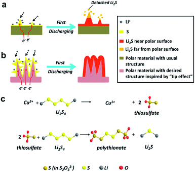
Polar materials are supposed to form relatively strong chemical bonds with LiPS, thus effectively keeping them within the cathode. This approach has been reported for metal oxides based on their polar interaction with polysulfides,16–18 nitrogen and sulfur dual-doped carbon via the functional groups,19 and metal organic frameworks (MOF) owing to Lewis acid–base interactions.20 Recently, MnO2 nanosheets have been used as an effective Li–S host, in which the soluble polysulfides are chemically trapped by a different mechanism, namely, sulfur-chain catenation.21–24 It was also proposed that sulfur-chain catenation is selectively triggered by metal oxides with a redox potential between 2.4 V < E° ≤ 3.05 V.25 However, most of these host materials are in the form of either two-dimensional (2D) nanosheets or nanocrystals and have a low surface area, which cannot effectively restrict the polysulfides within the cathode framework. In this case, discharge product (Li2S) particles are detached from the oxide matrix and may become electrochemically inactive (Fig. 1a). This results in the uncontrollable precipitation of Li2S on the polar surface, which leads to the further decay of capacity.26 Thus, it's important to design an ideal sulfur host with controlled shapes and desired chemical compositions to realize the uniform deposition of discharge/charge products, improving the battery performance.
The “tip effect” has been intensively researched in many aspects of modern science and technology in recent years, which can also explain the formation mechanism of the dendritic lithium growth.27–29 Based on the effect, it is suggested that the more projecting the part of the surface, the more is the surface field intensity distributed, which can easily absorb Li ions.30 In this regard, a host with 3D structure built from abundant protrusive building blocks should be beneficial to the homogenous precipitation of discharge/charge products and enable an intimate combination of Li2S with the conductive matrix (Fig. 1b). Such a composite cathode must be favorable for the reversible electrochemical reaction in the following charging process.
In this work, dandelion-like hollow cupric oxide spheres (HCOS) were fabricated as a new and effective host for the sulfur cathode. A monoclinic cupric oxide (CuO), as an important p-type transition metal oxide semiconductor material, possesses a redox potential of 2.53 V, thus promoting polythionate formation (Fig. 1c).25 Accordingly, CuO can be an efficient material in restricting sulfur and polysulfides in the cathode of Li–S batteries. In addition, the unique architecture of the 3D HCOS is beneficial to its electrochemical performance. With the above merits, the fabricated sulfur cathode is expected to display significant improvements in both the cycling stability and rate capability. Further, this design presents a new strategy to enhance electrochemical kinetics by structural and chemical dual-optimization, and can also be applied to other metallic hosts.
A novel yet facile solution synthesis was developed to fabricate the HCOS host, promising them real-world applications (Fig. S1†). The 3D unique structure of the HCOS was generated in the following organizing steps: (1) nanoribbons of CuO spontaneously attached into rhombic crystal strips and (2) the in situ formed crystal strips then self-assembled into dandelion-like architectures with hollow interiors. This one-pot hierarchical organization design relies primarily on geometric constraints of building units.31
Fig. 2a and b show the meso and micro-morphologies of the as-prepared HCOS samples. Interestingly, the CuO crystallites self-organized into dandelion-like hollow spheres (Fig. 2c), with diameters of about 2 μm. The thickness of the shell wall is about one half of the sphere radius (Fig. 2d). TEM images reveal that the HCOS are in fact built from small crystal strips that contain even smaller one-dimensional nanoribbons with the breadth of about 10–20 nm (Fig. 2e and S2a†). These outmost crystal strips can easily absorb Li ions due to the “tip effect”, which promotes uniform and rapid electrochemical reactions during cycling. Moreover, the flexibility of the protrusive crystal strips accommodates the volume expansion of the active sulfur, thus preserving the structural integrity of the electrode. Crystal lattice fringes of d![[2 with combining macron]](https://www.rsc.org/images/entities/char_0032_0304.gif) 02 (0.268 nm) and d020 (0.292 nm) along the CuO nanoribbons were easily detected from HRTEM investigation (Fig. 2f), which are consistent with the diffraction direction of as-synthesized HCOS (Fig. 3a). Afterwards, sulfur was infiltrated into the HCOS host by a conventional melt-impregnation method.22 The HCOS–S composites maintained the morphology of the HCOS host (Fig. S2b†), and the elemental mapping revealed that S is uniformly distributed on the surface of the HCOS host (Fig. S3†), which are necessary for our above design. According to the TGA result (Fig. S4†), the S content in the HCOS–S composite is ∼70 wt%.
02 (0.268 nm) and d020 (0.292 nm) along the CuO nanoribbons were easily detected from HRTEM investigation (Fig. 2f), which are consistent with the diffraction direction of as-synthesized HCOS (Fig. 3a). Afterwards, sulfur was infiltrated into the HCOS host by a conventional melt-impregnation method.22 The HCOS–S composites maintained the morphology of the HCOS host (Fig. S2b†), and the elemental mapping revealed that S is uniformly distributed on the surface of the HCOS host (Fig. S3†), which are necessary for our above design. According to the TGA result (Fig. S4†), the S content in the HCOS–S composite is ∼70 wt%.
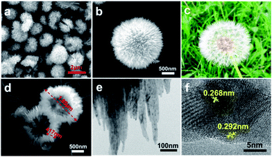 | ||
| Fig. 2 (a, b and d) SEM of the HCOS. (c) Image of a dandelion to compare with HCOS. (e) TEM and (f) HRTEM images of the HCOS. | ||
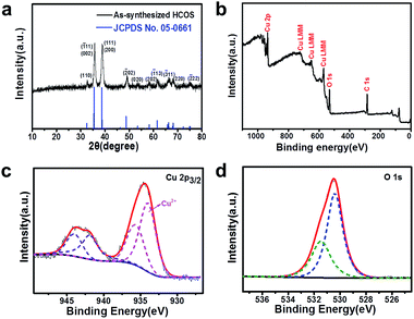 | ||
| Fig. 3 (a) XRD pattern and (b) XPS spectrum of the HCOS. High-resolution spectra of (c) Cu 2p and (d) O 1s for the HCOS. | ||
The XRD pattern (Fig. 3a) indicates that the as-synthesized HCOS can be indexed as a monoclinic phase of tenorite-type CuO (JCPDS No. 05-0661; space group: C2/c; ao = 4.684 Å, bo = 3.425 Å, co = 5.129 Å, β = 99.47°). XPS was used to further investigate the chemical composition. The peaks corresponding to Cu 2p (934.9 eV), Auger LMM (725.9, 648.9 and 569.9 eV) and O 1s (531.9 eV) are clearly observed (Fig. 3b).32 The main peaks of Cu 2p3/2 lie at 934.0 and 935.7 eV, respectively, which can be assigned to Cu2+ ions (Fig. 3c). The O 1s core-level spectrum is shown in Fig. 3d. The peak at 530.4 eV is in agreement with the lattice oxygen in CuO, and the peak at 531.5 eV can be assigned to the chemisorbed oxygen caused by surface hydroxyl, which corresponds to O–H bonds.33
The specific surface area (SSA) and the pore size of the HCOS host were determined by the nitrogen adsorption–desorption isotherms and the pore size distribution curves, as derived from BET measurements, are shown in Fig. S5.† The curves suggest that HCOS have a large BET specific surface area of 85 m2 g−1. The high surface area and pore volume, as well as the hierarchical porosity, are reasons for the high intrinsic polysulfide adsorptivity and enhanced electrolyte penetration into the thick electrodes.34
The superior intrinsic adsorption of Li2S4 for HCOS can be seen in the optical picture in Fig. S6.† Untreated Li2S4 solution was used as a comparison. The solution of HCOS and Li2S4 was colorless after stirring for 1 h, indicating strong adsorption. However, the graphene solution with Li2S4 remained intense yellow-gold. XPS analysis was further conducted on the obtained precipitate to investigate the chemical interaction of HCOS with LiPS (Fig. S7†). The S 2p spectra show two S 2p3/2 contributions at 161.7 and 162.9 eV, as expected for the terminal (ST−1) and bridging sulfur (S0B). Peaks between 166 and 170 eV correspond to two sulfur environments, one at 167.2 eV (thiosulfate) and another at 168.2 eV which is assigned to a polythionate complex.23 In addition, the Cu 2p spectrum shows that the surface of HCOS is partially reduced to Cu1+. The overall redox process is summarized in Fig. 1c. We propose that the HCOS host reacts with initially formed LiPS to form surface-bound intermediates, thiosulfate species. As reduction proceeds, these thiosulfate groups function as a transfer mediator to catenate higher polysulfides to form polythionates and insoluble lithium sulfides. The LiPS intermediates are thus anchored, resulting in high-performance cathodes.
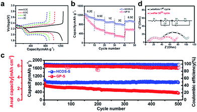
To evaluate the electrochemical performance of the HCOS–S composites, half cells were fabricated with a sulfur mass loading of ∼3.5 mg cm−2. For comparison, the GP-S composite was also prepared and made into half cells. The charge and discharge curves of the battery at various rates are depicted in Fig. 4a. It can be seen that every discharge profile presents two typical plateaus around 2.3 and 2.1 V, which are attributed to a reduction of cyclic S8 to long chain LiPS (Li2Sx, 4 ≤ x ≤ 8), and further reduction to Li2S2 and Li2S, respectively.35 As expected, the CV curves are consistent with the discharge/charge profiles of the HCOS–S composites and show a good stability during scanning (Fig. S8†). The discharge capacities were around 1246, 1018, 900 and 830 mA h g−1 when the batteries were cycled at 0.2, 0.5, 1 and 2C, respectively, as shown in Fig. 4b. When the current density was abruptly switched back to 0.5C, a discharge capacity of 939 mA h g−1 was recovered. The excellent rate performance of the HCOS–S cathode is attributed to the large surface area and electrochemical activity of the electrode during cycling, thus leading to faster kinetics.
HCOS–S also exhibited good cycling stability (Fig. 4c and S9†). The initial capacity of HCOS–S was 1015 mA h g−1, corresponding to a desirable areal capacity of 3.6 mA h cm−2. After 500 cycles, a capacity of 883 mA h g−1 was maintained with an average coulombic efficiency of over 98%. Moreover, the discharge/charge profiles present a stable voltage plateau and small capacity loss during cycling, which further demonstrates the improved electrochemical properties (Fig. S9†). In contrast, GP-S had a similar initial capacity but displayed faster capacity fading, and only a capacity of 349 mA h g−1 and coulombic efficiency of 90% were obtained. The decay probably resulted from the low conversion rate of S-containing species on graphene and uncontrollable Li2S growth, which led to surface poisoning by unreacted polysulfides and electrochemical inactivity of the electrode, weakening its suppression of polysulfide shuttle. Whereas, the 3D HCOS with crystal strips allows the full utilization of polysulfides within the cathode and is favorable for the controllable precipitation of Li2S. Further cyclic stability of the cells built with only HCOS as the cathode reveals a negligible capacity contribution of ∼14 mA h g−1 to the overall capacity (Fig. S10†), demonstrating that the HCOS host itself is not electrochemically active in the applied potential window (1.8–2.8 V).
To analyze the conductivity of the electrode in Li–S batteries, the EIS measurements were performed. The Nyquist plots of the HCOS–S electrodes before and after cycling are shown in Fig. 4d with a simplified equivalent circuit model. The semicircle located in the lower-frequency region corresponds to the charge transfer resistance (Rct) of the cell. There is also a semicircle in the higher-frequency region, corresponding to the deposit diffusion resistance of the SEI film (Rg).36Rct decreased after 50 cycles for the HCOS–S cell, indicating that the HCOS–S composite exhibits the high sulfur utilization and little shuttle phenomenon. This phenomenon results from the good combination between the active S-containing species and the HCOS host during cycling and the enhanced conductivity, which is beneficial to the electrochemical reaction activity. In addition, Rg remained unchanged, indicating that the relocation of sulfur active materials on the surface of the HCOS reduced the formation of the passivation layer on the electrodes upon cycling.37 This also promotes the high rate capability of the sulfur cathode.
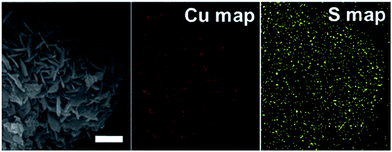
The structure after the electrochemical test was examined through high magnification SEM and TEM (Fig. 5 and S11†). The result showed that the structure of the HCOS host was preserved after long cycling, and elemental S was still well dispersed on the surface of the HCOS after 500 cycles. This is further evidence of the uniform deposition of Li2S during cycling, which allows for a high degree of S utilization to realize high specific capacity and fast electrochemical kinetics.38 In addition, the void space between the crystal strips can also accommodate the volume expansion of sulfur during lithiation, thus preserving the structural integrity of the host.
To the best of our knowledge, it can be noted that the HCOS–S electrode of this work exhibits much enhanced areal capacities and higher cycling stability at high sulfur loading (Table S1†). The significant improvement in electrochemical performance can be possibly attributed to the following advantages of the HCOS host: (1) HCOS can react with polysulfides to form surface-bound polythionate species, which can dynamically promote the kinetics of the polysulfide redox reaction and also prevent the polysulfide shuttling in the electrolyte. (2) The 3D hollow porous structure affords a large surface area for high sulfur loading and adequate space for alleviating the considerable volume change upon cycling, thus giving rise to the structural stability of the host. (3) The engineered dandelion-like HCOS with many extended crystal strips provides plenty of active positions for rapid and controllable deposition of discharge/charge products and also allows efficient transport of electrons.
Conclusions
In summary, inspired by the well-known “tip effect”, 3D HCOS with an appropriate structure were designed and synthesized by a facile method and used as a sulfur host material with high performance in Li–S batteries. When used as the polar host, they demonstrated the capability of promoting stable redox activity by using a transfer mediator, preserving the structural integrity of the host and providing abundant active sites for rapid and homogeneous deposition of discharge/charge products. With these multiple advantages, a high capacity of 1015 mA h g−1, good capacity retention, and stable cycling over 500 cycles were obtained with a high sulfur loading of 3.5 mg cm−2. This work opens a path for employing the chemical interactions to bond polysulfides with rationally designed structures for the sulfur cathode in Li–S batteries.Acknowledgements
This work was supported by the National Natural Science Foundation of China (21376001 and 21506012) and the Beijing Higher Education Young Elite Teacher Project (YETP1205).Notes and references
- S. Bai, X. Liu, K. Zhu, S. Wu and H. Zhou, Nat. Energy, 2016, 1, 16094 CrossRef CAS.
- J. Yang, F. Chen, C. Li, T. Bai, B. Long and X. Zhou, J. Mater. Chem. A, 2016, 4, 14324–14333 CAS.
- Q. Pang, X. Liang, C. Y. Kwok and L. F. Nazar, Nat. Energy, 2016, 1, 16132 CrossRef CAS.
- Z. Liu, X. Zheng, S.-L. Luo, S.-Q. Xu, N.-Y. Yuan and J.-N. Ding, J. Mater. Chem. A, 2016, 4, 13395–13399 CAS.
- Q. Fan, W. Liu, Z. Weng, Y. Sun and H. Wang, J. Am. Chem. Soc., 2015, 137, 12946–12953 CrossRef CAS PubMed.
- C. B. Bucur, J. Muldoon and A. Lita, Energy Environ. Sci., 2016, 9, 992–998 CAS.
- B. Li, S. Li, J. Xu and S. Yang, Energy Environ. Sci., 2016, 9, 2025–2030 CAS.
- S. Lu, Y. Cheng, X. Wu and J. Liu, Nano Lett., 2013, 13, 2485–2489 CrossRef CAS PubMed.
- S. Lu, Y. Chen, J. Zhou, Z. Wang, X. Wu, J. Gu, X. Zhang, A. Pang, Z. Jiao and L. Jiang, Sci. Rep., 2016, 6, 20445 CrossRef CAS PubMed.
- Y. Yang, W. Sun, J. Zhang, X. Yue, Z. Wang and K. Sun, Electrochim. Acta, 2016, 209, 691–699 CrossRef CAS.
- S. Lu, Y. Chen, X. Wu, Z. Wang and Y. Li, Sci. Rep., 2014, 4, 4629 Search PubMed.
- Z. Wang, J. Zhang, Y. Yang, X. Yue, X. Hao, W. Sun, D. Rooney and K. Sun, J. Power Sources, 2016, 329, 305–313 CrossRef CAS.
- Y. Chen, S. Lu, X. Wu and J. Liu, J. Phys. Chem. C, 2015, 119, 10288–10294 CAS.
- G. Hu, C. Xu, Z. Sun, S. Wang, H. M. Cheng, F. Li and W. Ren, Adv. Mater., 2016, 28, 1603–1609 CrossRef CAS PubMed.
- Z. W. Seh, Y. Sun, Q. Zhang and Y. Cui, Chem. Soc. Rev., 2016, 45, 5605 RSC.
- S. Rehman, S. Guo and Y. Hou, Adv. Mater., 2016, 28, 3167–3172 CrossRef CAS PubMed.
- Y. Chen, S. Lu, J. Zhou, X. Wu, W. Qin, O. Ogoke and G. Wu, J. Mater. Chem. A, 2017, 5, 102–112 CAS.
- J. Jiang, J. Zhu, W. Ai, X. Wang, Y. Wang, C. Zou, W. Huang and T. Yu, Nat. Commun., 2015, 6, 8622 CrossRef CAS PubMed.
- Q. Pang, J. Tang, H. Huang, X. Liang, C. Hart, K. C. Tam and L. F. Nazar, Adv. Mater., 2015, 27, 6021–6028 CrossRef CAS PubMed.
- Y.-J. Li, J.-M. Fan, M.-S. Zheng and Q.-F. Dong, Energy Environ. Sci., 2016, 9, 1998–2004 CAS.
- X. Liang and L. F. Nazar, ACS Nano, 2016, 10, 4192–4198 CrossRef CAS PubMed.
- Z. Li, J. Zhang and X. W. Lou, Angew. Chem., Int. Ed., 2015, 54, 12886–12890 CrossRef CAS PubMed.
- X. Liang, C. Hart, Q. Pang, A. Garsuch, T. Weiss and L. F. Nazar, Nat. Commun., 2015, 6, 5682 CrossRef PubMed.
- W. Sun, X. Ou, X. Yue, Y. Yang, Z. Wang, D. Rooney and K. Sun, Electrochim. Acta, 2016, 207, 198–206 CrossRef CAS.
- X. Liang, C. Y. Kwok, F. Lodi-Marzano, Q. Pang, M. Cuisinier, H. Huang, C. J. Hart, D. Houtarde, K. Kaup, H. Sommer, T. Brezesinski, J. Janek and L. F. Nazar, Adv. Energy Mater., 2016, 6, 1501636 CrossRef.
- X. Tao, J. Wang, C. Liu, H. Wang, H. Yao, G. Zheng, Z. W. Seh, Q. Cai, W. Li, G. Zhou, C. Zu and Y. Cui, Nat. Commun., 2016, 7, 11203 CrossRef CAS PubMed.
- L. Enze, J. Phys. D: Appl. Phys., 1986, 19, 1 CrossRef CAS.
- R. Zhang, X. B. Cheng, C. Z. Zhao, H. J. Peng, J. L. Shi, J. Q. Huang, J. Wang, F. Wei and Q. Zhang, Adv. Mater., 2016, 28, 2155–2162 CrossRef CAS PubMed.
- X. B. Cheng, T. Z. Hou, R. Zhang, H. J. Peng, C. Z. Zhao, J. Q. Huang and Q. Zhang, Adv. Mater., 2016, 28, 2888–2895 CrossRef CAS PubMed.
- L. Enze, J. Phys. D: Appl. Phys., 1987, 20, 1609 CrossRef.
- B. Liu and H. C. Zeng, J. Am. Chem. Soc., 2004, 126, 8124–8125 CrossRef CAS PubMed.
- M. C. Biesinger, L. W. M. Lau, A. R. Gerson and R. S. C. Smart, Appl. Surf. Sci., 2010, 257, 887–898 CrossRef CAS.
- C. Chen, Y. Dong, S. Li, Z. Jiang, Y. Wang, L. Jiao and H. Yuan, J. Power Sources, 2016, 320, 20–27 CrossRef CAS.
- Q. Pang, D. Kundu and L. F. Nazar, Mater. Horiz., 2016, 3, 130–136 RSC.
- Z. Yuan, H. J. Peng, T. Z. Hou, J. Q. Huang, C. M. Chen, D. W. Wang, X. B. Cheng, F. Wei and Q. Zhang, Nano Lett., 2016, 16, 519–527 CrossRef CAS PubMed.
- T. A. Zegeye, C.-F. J. Kuo, A. S. Wotango, C.-J. Pan, H.-M. Chen, A. M. Haregewoin, J.-H. Cheng, W.-N. Su and B.-J. Hwang, J. Power Sources, 2016, 324, 239–252 CrossRef CAS.
- C. Zu, Y. S. Su, Y. Fu and A. Manthiram, Phys. Chem. Chem. Phys., 2013, 15, 2291–2297 RSC.
- H.-J. Peng, W.-T. Xu, L. Zhu, D.-W. Wang, J.-Q. Huang, X.-B. Cheng, Z. Yuan, F. Wei and Q. Zhang, Adv. Funct. Mater., 2016, 26, 6351–6358 CrossRef CAS.
Footnote |
| † Electronic supplementary information (ESI) available: Details of the experiment; TEM images; TGA curves; N2-sorption isotherms and pore-size distribution; adsorption experiment and mechanism; and cycling performance of the battery with only HCOS as the cathode. See DOI: 10.1039/c6ta09322a |
| This journal is © The Royal Society of Chemistry 2017 |

