 Open Access Article
Creative Commons Attribution 3.0 Unported Licence
Electrochemical properties of a rechargeable aluminum–air battery with a metal–organic framework as air cathode material
Ryohei Mori
Fuji Pigment Co. Ltd, 2-23-2 Obana, Kawanishi-city, Hyogo Prefecture 666-0015, Japan. E-mail: moriryohei@fuji-pigment.co.jp; Fax: +81-72-7599008; Tel: +81-72-7598501
First published on 19th January 2017
Abstract
The goal of this study was to develop a rechargeable aluminum–air battery with high capacity and long-term durability in charge–discharge electrochemical reactions. We used aluminum terephthalate as a metal–organic framework (MOF) material for the air cathode and 1-ethyl-3-methylimidazolium chloride as an ionic liquid electrolyte. When we used aluminum terephthalate as an air cathode material, the electrical power output and cell capacity were lower than that attained with the cell using activated carbon as air cathode material. However, the cell capacity, cyclic voltammetry behavior, and cell interfacial impedance was more stable over repeated electrochemical reactions when the MOF was used as an air cathode material. In addition, we did not observe Al(OH)3 and Al2O3 on the anode electrodes, which are byproducts that inhibit aluminum–air battery function.
Introduction
Metal–air batteries have attracted attention in electrochemical research and development in the last 50 years because they have specific energies that are much higher than those of most of the available primary and rechargeable batteries such as Li ion, Ni–Cd, and lead–acid batteries. For these batteries, active metals such as Li, Ca, Mg, Al, Fe, and Zn may be used as anode materials.1 Aluminum (Al), the most abundant metal in the Earth's crust, is particularly a highly attractive energy source because of its physical and chemical properties. The low atomic weight (28.98 g mol−1) and trivalence oxidation of Al results in its low gram-equivalent weight (8.99) and ultrahigh specific gravimetric capacity (2.89 A h g−1). Relative to Al, only lithium has a slightly higher electrochemical equivalent (3.86 A h g−1). Furthermore, the theoretical specific volumetric capacity of Al is the highest among the metallic fuels (8.04 A h cm3). These advantages, as well as its low price-per-energy unit has increased interest in its use as an anode material in battery systems, specifically, in alkaline metal–air batteries.2,3 A major barrier to commercialization of such batteries, however, is the high rate of aluminum self-corrosion in alkaline solutions both under open-circuit conditions and during discharge. Efforts to suppress this parasitic corrosion include doping of high-purity aluminum (99.999% grade) with specific alloying elements4 and introducing corrosion inhibitors into its electrolyte.5 However, the above approaches have not led to commercial production of aluminum–air batteries because byproducts such as Al2O3 and Al(OH)3 accumulate at both the anode and cathode. To prevent accumulation of byproducts and corrosion of the anode due to direct contact with the electrolyte while retaining aluminum ion conduction, we coated an aluminum anode and air cathode with a ceramic oxide or carbon materials in our previous studies.6–11 Ionic liquids have been used as an electrolyte for aluminum electrodeposition in recent studies.12,13 In our recent work on the effect of the air cathode material for an aluminum–air battery using the electrolyte 1-ethyl 3-methylimidazolium chloride, we found that the perovskite oxide lanthanum strontium cobalt ferrite (La0.6Sr0.4Co0.2Fe0.8O3) is electrochemically stable and thus practical for air cathode materials.14Metal–organic frameworks (MOFs) have evoked tremendous attention in the past few decades because of their intriguing structural diversity, simple synthetic processes, and low cost, as well as pore size, which can be controlled by changing the length of organic ligands. The surface area of MOFs can be as large as 7000 m2 g−1, which exceeds that of most traditional porous materials. The unique properties of MOFs such as large surface area, tunable pore size, high porosity, low density, controllable structure, and controllable functional ligands have been enabled their use in catalysts, luminescence applications, magnets, nonlinear optics, gas storage, and separation processes.15 Recently, studies on MOFs have focused on MOF design and synthesis for clean-energy applications such as fuel cells,16 lithium ion rechargeable batteries,17 supercapacitors18 and solar cells.19 To our knowledge, there have been no studies on the effect of MOFs on aluminum–air batteries. In the present study, we examined the effect of using aluminum terephthalate (AT) as an active material for an air cathode for aluminium air batttery, particularly, its effect on the long-term cell capacity in electrochemical reactions.
Materials and methods
An aluminum board (Al A1050, 99.5% purity) was used as an anode. Conductive carbon was purchased from Denka Co. Ltd. Japan. The air cathode was composed of air cathode material/conductive carbon/polyvinylidene difluoride/N-methylpyrrolidone solution (1![[thin space (1/6-em)]](https://www.rsc.org/images/entities/char_2009.gif) :
:![[thin space (1/6-em)]](https://www.rsc.org/images/entities/char_2009.gif) 0.2
0.2![[thin space (1/6-em)]](https://www.rsc.org/images/entities/char_2009.gif) :
:![[thin space (1/6-em)]](https://www.rsc.org/images/entities/char_2009.gif) 1
1![[thin space (1/6-em)]](https://www.rsc.org/images/entities/char_2009.gif) :
:![[thin space (1/6-em)]](https://www.rsc.org/images/entities/char_2009.gif) 4 ratio) on a nickel-mesh current collector. The air cathode materials used in this study were activated carbon (AC) and AT. To determine the effect of using the MOF as air cathode material, a sample without conductive carbon was also prepared. A mixture of 1-ethyl-3-methylimidazolium chloride and AlCl3 (1
4 ratio) on a nickel-mesh current collector. The air cathode materials used in this study were activated carbon (AC) and AT. To determine the effect of using the MOF as air cathode material, a sample without conductive carbon was also prepared. A mixture of 1-ethyl-3-methylimidazolium chloride and AlCl3 (1![[thin space (1/6-em)]](https://www.rsc.org/images/entities/char_2009.gif) :
:![[thin space (1/6-em)]](https://www.rsc.org/images/entities/char_2009.gif) 2 molar ratio) was prepared and used as an electrolyte. All of other chemicals were purchased from Sigma Aldrich Corporation (Saint Louis, USA). The average particle size and BET surface area of aluminum terephthalate were 31.5 μm and 1100–1500 m2 g−1, respectively, according to Sigma Aldrich information. Phases of the anode were studied by X-ray diffraction (XRD) measurements on a RAD-RU diffractometer (Rigaku Corp., Tokyo, Japan) using Cu Kα radiation and operated at 40 kV and 200 mA. XPS measurement was carried out on a PHI5000 VersaProbe II spectrometer (Ulvac-Phi Inc. MN, USA). The electrochemical performance was evaluated by using a galvanostat (SP-150; BioLogic, France). Cyclic voltammetry was carried out at a scan rate of 10 mV s−1. All electrochemical measurements were made under ambient atmospheric conditions.
2 molar ratio) was prepared and used as an electrolyte. All of other chemicals were purchased from Sigma Aldrich Corporation (Saint Louis, USA). The average particle size and BET surface area of aluminum terephthalate were 31.5 μm and 1100–1500 m2 g−1, respectively, according to Sigma Aldrich information. Phases of the anode were studied by X-ray diffraction (XRD) measurements on a RAD-RU diffractometer (Rigaku Corp., Tokyo, Japan) using Cu Kα radiation and operated at 40 kV and 200 mA. XPS measurement was carried out on a PHI5000 VersaProbe II spectrometer (Ulvac-Phi Inc. MN, USA). The electrochemical performance was evaluated by using a galvanostat (SP-150; BioLogic, France). Cyclic voltammetry was carried out at a scan rate of 10 mV s−1. All electrochemical measurements were made under ambient atmospheric conditions.
Results and discussion
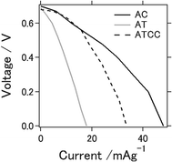
Fig. 1 shows I–V curves of the aluminum–air battery prepared in the study. We explain in the following section the experimental results for the battery using the materials AC, AT (as MOF material only), and AT with conductive carbon (ATCC) for the air cathode. Use of AT and ATCC as air cathode materials resulted in electrical power output lower than that achieved with AC. Short-circuit currents attained with AT and ATCC were, respectively, about 37.3 and 70.1% of that attained with AC. The open-circuit potential was approximately 0.7 V for all air cathodes that were tested. The electrochemical properties of the aluminum–air battery depend on many factors, including quality and chemical composition of the aluminum anode, electrolyte composition, air cathode, and the preparation procedure for the entire cell.20 The open-circuit potential in our previous study in which we used aqueous electrolyte was approximately 1.2–1.3 V, which is higher than that obtained with use of an ionic liquid as an electrolyte.21 The short-circuit current was also lower, a consequence of the lower catalytic activity of AT22 in oxygen reduction. Use of AT without any conductive carbon as air cathode material seemed to result in insufficient conductivity of the air cathode for achieving the desired electrical properties for the battery. This is the first report of the use of a MOF as an electrode material for an aluminum–air battery.Fig. 2a displays charge–discharge curves of the prepared aluminum–air batteries with an applied current of 4 mA g−1. The capacities of the battery using AC at the 1st, 5th, and 25th cycles were 154, 136, and 28 mA h g−1, respectively. Those of the batteries using AT and ATCC were 22, 20, and 20 mA h g−1 and 87, 77, and 57 mA h g−1, respectively. As explained above, the low catalytic activity of AT in oxygen reduction may account for the low cell capacity in the first cycle. The capacities of the cells using AC and ATCC after 25 cycles respectively decreased to approximately 18.2% and 63.6% of their initial capacities. Although the cell capacity was lower at the first cycle, its value after 25 cycles remained almost the same when we used AT as the material for the air cathode. Therefore, use of AT as MOF for the air cathode resulted in high durability of the aluminum–air battery system in repetitive charge–discharge electrochemical reactions. One of the feature of ionic liquid is that it is able to bear high voltage bias when utilized as the electrolyte for batteries. Based on this feature, ionic liquid is practically applied for electric double layer capacitor and partly for lithium ion battery.23,24 However, when ionic liquid is used as the electrolyte for Al air battery, open circuit voltage is low because theoretical voltage of aluminium is lower than that of lithium.21 In addition, please note that when upper limit is set as 2.0 V as cyclic voltammetry measurement, charge curve could not reach 2.0 V even with extended charging time. Therefore, we set upper limit as lower voltage even potential range is different from cyclic voltammetry measurement which will be presented in next figure.
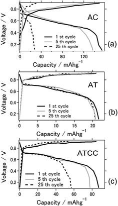 | ||
| Fig. 2 Charge–discharge curves for the aluminum–air battery with the air-cathode materials (a) AC (b) AT and (c) ATCC. | ||
Cyclic voltammograms between 0 and 2.0 V for the batteries at the 1st, 5th, and 25th cycles (Fig. 3) were obtained to characterize the redox reactions. The cyclic voltammogram for the battery with the AC air cathode became flatter after the 25th cycle, indicating deterioration of the electrochemical reaction, similar to the result explained above. An explanation for this phenomenon is the deterioration of the cathode due to carbon combustion by active oxygen species during charging.23 Oxygen reduction reaction is a multi-electron chemical reaction taking place in the cathode side with two main possible pathways: one pathway involves the transfer of 2e− to produce peroxide (H2O2), and the other is production of water via a direct 4e− transfer. These two pathways can be presented in following equations24
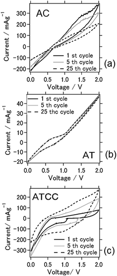 | ||
| Fig. 3 Cyclic voltammograms of the aluminum–air battery with the air-cathode materials (a) AC (b) AT and (c) ATCC. | ||
Direct 4 electron pathway:
| O2 + 4H+ + 4e− → 2H2O |
2 electron pathway:
| O2 + 2H+ + 2e− → 2H2O2 |
| 2H2O2 + 2H+ + 2e− → 2H2O |
The oxygen reduction reaction (ORR) kinetics is very slow and needs a catalyst to facilitate the reaction by changing the mechanism. A desired catalyst would reduce oxygen molecules to water via 4-electrons pathway which is generally possible by perovskite material such as LSCF.14 For 2 electron pathway case as being air cathode material as carbonaceous material, because an incomplete reduction of oxygens to hydrogen peroxide through 2-electrons route, leads to low energy conversion efficiency, hydrogen peroxide further decomposes to harmful free radical species which degrades the ionic conductive materials as we have seen the deterioration of air cathode material in our case also.25
When we used AT as air cathode, the anodic–cathodic electrochemical reaction was weak, and the cyclic voltammetry profiles were very stable even after 25 cycles. Even after 100 cycles, the battery using AT produced a stable cyclic voltammogram (data not shown). This result coincides with the results in Fig. 2, which depict a stable cell capacity over 25 charge–discharge cycles. When ATCC was used as air cathode material, cathodic peaks were observed to appear within the range of 1.0–1.3 V. These peaks disappeared and the anodic–cathodic reaction ceased after 25 cycles. This disappearance is probably due to the electrochemical reaction in the early stage resulting from the use of the MOF and conductive carbon materials. The carbon materials subsequently combusted, as explained above, and its effect disappeared after repeated cell cycles. It should be noted that 1-ethyl-3-methylimidazolium chloride is hydrophilic and absorb moisture from ambient atmosphere. The relation between electrochemical reaction and moisture content in ionic liquid needs to be further scrutinized.
The aluminum–air battery using chloroaluminate ionic liquid as electrolyte exhibited Lewis acid–base chemistry that is comparable to Brønsted acidity in water. Just as the proton concentration controls the electrochemistry in aqueous solution, chloroacidity is the major determinant of speciation, reactivity, and electrochemistry in the ionic liquid. The composition of the melt determines its chloroacidity. As the chloride donor undergoes stepwise Lewis acid–base reactions with the acid AlCl3, chloroaluminate anions form according to the following equilibrium reactions:
| Cl− (l) + AlCl3 (s) ↔ AlCl4− (l) k = 1.6 × 10¹⁹ |
| AlCl4− (l) + AlCl3 (s) ↔ Al2Cl7− (l) k = 1.6 × 10³ |
| Al2Cl7− (l) + AlCl3 (s) ↔ Al3Cl10− (l) k = 1.0 × 10 |
The distribution diagram for the anionic species in 1-ethyl-3-methylimidazolium chloride suggests that AlCl3 associates with these equilibrium constants. At <0.5 mole fraction of AlCl3 in the room-temperature liquid melt, the only anions present in significant quantities are the Lewis bases Cl− and AlCl4−, making the melt basic. At AlCl3 mole fractions greater than 0.5, as in our study, the only anions present in appreciable amounts in the liquid are AlCl4− and Al2Cl7−. Since these anions are a potential source of the Lewis acid AlCl3, the melt may be acidic.26 Therefore, we hypothesize that AlCl4− and Al2Cl7− function as charge carriers on the anode in the aluminum–air battery.
| 4Al2Cl7− + 3e− → Al + 7AlCl4− |
The MOF AT provides stable adsorption–desorption sites for ions in the electrolyte in lithium-ion and lithium–air battery systems.27 Our study indicates that AT in the aluminum–air battery possesses catalytic activity in oxygen reduction. In addition, previous researches also have been reporting possible oxygen reduction reaction when ionic liquid is used as an electrolyte.21,26 The number of MOFs used in the lithium ion battery has been studied. Tarascon et al. first reported the use of the MOF FeIII(OH)0.8F0.2(O2CC6H4CO2)(MIL-53(Fe)) as cathode for lithium ion batteries. This MOF contains Fe(III) at higher oxidation state.28 Similar to other cathodes as the positive electrodes, the electrode was prepared by directly mixing MOFs with 15 wt% carbon. Mössbauer spectroscopic analysis showed that the capacity is due to uptake and removal of Li ions and the reversible reduction and oxidation of FeIII and FeII. The half-cell reaction on the cathode side is
| MIL-53(Fe) + xLi + xe− → LixMIL-53(Fe) |
Therefore, the cathode reactions in our aluminum–air battery system are
| 3AT (MOF) + xAl3+ + 3xe− → 3Al+AT (MOF) |
| 4Al + 3O2 → 2Al2O3 |
MOFs have also been used as an anode,29 an electrolyte,30 and a precursor for materials for lithium ion batteries.31 They have also been used in electrodes and as a precursor for supercapacitors because of their high specific surface area.32 When the aluminum anode was coated with AT in the present study, changes in cyclic voltammetry behaviors were not observed. Therefore, we no longer examined the influence of the MOF on the anode side. Regarding cathode side, MOF have been extensively studied in terms of its ORR/OER (Oxygen Evolution Reaction) catalytic activities. For example, MOF derivative porous carbon material is focused to be applied for especially in the field of catalytic material for PEFC. Carbon nanotube/graphene/graphene-oxide based metal–nitrogen–carbon structures are recent examples of such nano porous carbons that show superior catalytic activities for ORR or OER, compared with expensive Pt or Ir and Ru oxides.33–35 However, developing such nano porous carbon usually involves extensive chemical processes, thus hindering large scale commercial implementation. In contrast, the intrinsically open pore polymers with metal cores as sacrificial templates have proved extremely advantageous for the development of multifunctional nano porous carbons.36,37 The best example of such templates are metal–organic frameworks, which consist of small ligand molecules as linkers with metal centers to produce regularly ordered open frameworks of a high specific surface area.38–40 MOFs is clearly-defined three-dimensional structures. Transition metal could be ideally chosen to be doped into carbon and nitrogen doping can be grafted into MOFs with the highest possible volumetric density through regularly arranged cell structure.41 The MOF surface area and pore size are tunable by the length of the linker. The organic linkers would be converted to carbon during thermal activation while maintaining the porous framework, leading to catalysts with high surface area and uniformly distributed active sites without the need of a second carbon support or pore forming agent. On the other hand, not being used as nano porous carbon templates but MOF itself has been studied as air cathode catalysts for Li–O2 batteries. Their micropores can greatly contribute to O2 transport, and their mesopores are well-suited for electrolyte diffusion and product deposition. Wu et al. used three types of MOFs, namely, MOF-5, HKUST-1, and M–MOF-74 (M = Mg, Mn, Co), as cathode materials for Li–O2 batteries.42 Mn–MOF-74 has a primary capacity of 9420 mA h g−1. The reaction of O2 molecules in its pores is enhanced by accessible open metal sites in uniform channels. Furthermore, oxygen evolution reaction of metal organic framework has been reported recently.43,44 Thus, it can be suggested that MOF material performed well in our aluminum–air battery system because of their high surface area, hierarchical porosity, and uniformly dispersed active sites.
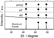
XRD patterns of an intact aluminum anode and the anode used in the electrochemical reaction are presented in Fig. 4. Similar to the intact aluminum anode, the latter had an aluminum phase only, irrespective of the kind of air cathode used. In contrast to the results of our previous studies, we did not detect the major byproducts Al(OH)3 nor Al2O3 phases, which inhibit long-term operation of the aluminum–air battery.6–11 Similarly, byproducts were not observed when ionic liquid was used as an electrolyte for the other air cathode materials.14,21
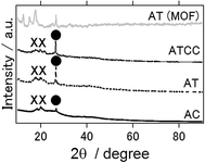
Fig. 5 presents the XRD patterns of air cathode after the electrochemical reaction, and XRD pattern of intact aluminium terephthalate as MOF itself. In contrast to anode, even ionic liquid is used as an electrolyte, Al2O3 and Al(OH)3 phases were detected as byproducs. This result is the same as previous study in which Gelman et al. have applied ionic electrolyte as an electrolyte for aluminium air battery.21 In addition, even inside of MOF air cathode could maintain the structure and the phase of the MOF, it seems that the surface of MOF is covered or destroyed with Al2O3 and Al(OH)3 phases after electrochemical reaction.
Fig. 6 presents the XPS spectra of intact aluminium anode and the anodes with AC, AT, ATCC air cathode after the electrochemical reaction. 2p orbital of aluminium atom generally have peaks around 73 eV. One can confirm that even intact aluminium have peak approximately at 74 eV which indicates that aluminium exists as aluminium oxides or aluminium chloride.45 When we performed the etching of the surface of intact aluminium and measured again, the peak was 72.9 eV which indicates the metal aluminium. This is because the surface of aluminium metal can hardly exist as pure aluminium metal in normal atmosphere and forms thin layer of amorphous passivation of oxide which protects the underlying metal.46 Therefore, it is difficult to determine whether byproducts such as Al(OH)3 or Al2O3 are not formed on the surface after electrochemical reaction. However, at least one can say that byproducts were not formed as crystalline phase as we have observed in Fig. 4.
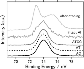 | ||
| Fig. 6 X-ray photoelectron spectra of Al 2p of aluminium anode before (intact aluminium), after etching, and after the electrochemical reaction (AC, AT, ATCC). | ||
Fig. 7 shows Bode plots for the aluminum–air batteries using AC, AT, and ATCC air cathodes, as a function of electrochemical reaction time. Overall, interfacial impedance did not increase much even after four days of electrochemical reaction. This result is in contrast to that in our previous research, in which we found a general increase in interfacial impedance when we used aqueous electrolyte due to byproduct accumulation on the electrodes.6–11 Therefore, the interfacial impedance did not increase drastically because byproducts did not accumulate on the electrodes when we used the ionic liquid as an electrolyte. For the aluminum–air batteries using AC and ATCC air cathodes, the interfacial resistance increased slightly after 96 h of electrochemical reaction. This result may indicate deterioration of the carbon material. For the AT air cathode material, the interfacial impedance was the same or even lower after 96 h of battery operation time. This result is expected since AT showed good long-term stability in electrochemical reactions.
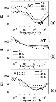 | ||
| Fig. 7 Bode plots of the aluminum–air battery with the air-cathode materials (a) AC (b) AT and (c) ATCC. | ||
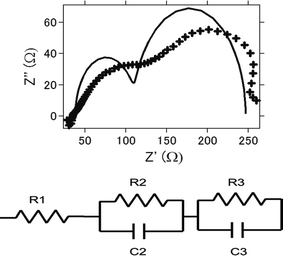
Impedance analysis is also performed. Fig. 8a presents the nyquist plot of the intact aluminum–air batteries with AC as air cathode before electrochemical reaction. Equivalent circuits for simulating the process are shown in Fig. 8b and the simulation values obtained by EC Lab software for the equivalent elements are listed in Table 1. Generally, it is regarded that R1 is regarded as the resistance of electrolyte solution as Rs (resistance of solution), and R2 is the resistance of charge carrier transfer at the electrode/electrolyte interface as Rc (resistance of charge transfer).47,48 R3 is regarded as the resistance of ion diffusion. For AC and ATCC, electrolyte solution, the charge transfer resistance and ionic diffusion resistance increased as charge–discharge reaction proceeds. This is suggested to be due to an incomplete reduction of oxygens to hydrogen peroxide through 2-electrons route.26,27 Furthermore, byproducts accumulation in the battery could be another major reason for resistance increase. On the other hand, even products were formed, impedance did not increase much for AT. This also coincides with the above results since AT showed good long-term stability in electrochemical reactions.
| 0 h | 48 h | 96 h | |
|---|---|---|---|
| AC | |||
| R1 (Ω cm2) | 98.54 | 288.47 | 598.41 |
| C2 (F cm−2) | 1.13 × 10⁻³ | 5.37 × 10⁻⁴ | 2.94 × 10⁻⁵ |
| R2 (Ω cm2) | 267.45 | 468.45 | 789.45 |
| C3 (F cm−2) | 2.50 × 10⁻⁵ | 8.39 × 10⁻⁶ | 1.62 × 10⁻⁶ |
| R3 (Ω cm2) | 72.54 | 86.58 | 114.658 |
![[thin space (1/6-em)]](https://www.rsc.org/images/entities/char_2009.gif) |
|||
| AT | |||
| R1 (Ω cm2) | 628.45 | 689.47 | 702.45 |
| C2 (F cm−2) | 5.36 × 10⁻⁶ | 2.64 × 10⁻⁶ | 2.03 × 10⁻⁶ |
| R2 (Ω cm2) | 914.54 | 981.54 | 997.56 |
| C3 (F cm−2) | 3.75 × 10⁻⁵ | 2.87 × 10⁻⁵ | 2.17 × 10⁻⁵ |
| R3 (Ω cm2) | 125.74 | 145.45 | 148.45 |
![[thin space (1/6-em)]](https://www.rsc.org/images/entities/char_2009.gif) |
|||
| ATCC | |||
| R1 (Ω cm2) | 189.47 | 228.93 | 358.74 |
| C2 (F cm−2) | 3.81 × 10⁻⁴ | 1.12 × 10⁻⁴ | 8.45 × 10⁻⁵ |
| R2 (Ω cm2) | 608.96 | 745.12 | 914.54 |
| C3 (F cm−2) | 1.58 × 10⁻⁵ | 9.41 × 10⁻⁶ | 2.39 × 10⁻⁶ |
| R3 (Ω cm2) | 110.54 | 118.45 | 148.57 |
The MOF, cell capacity, cyclic voltammetry behavior, and cell impedance were stable over long-term operation of the battery. We used the MOF as cathode material for the aluminum–air battery for the first time. MOF probably provides channels for the transport of aluminum-related ion and oxygen, space for the deposition of discharge products, and active sites for the reaction. Because of the unlimited choices of MOF, the following points must be carefully considered to create a better aluminum–air battery: (i) the O2 supply to the electrochemical reaction is hampered by the weak interaction between O2 molecules and the MOF electrode. (ii) Electrolyte and product deposition in the MOF pores block the path for O2 diffusion and thus impede the reaction. (iii) Without the full structural details of low periodicity of the MOF, some cells with the MOF lack highly repeatable electrochemical behavior; further improving their performance is thus likely difficult. We are carrying out further studies to find the best MOF material for our aluminum–air battery.
Conclusions
AT was used as MOF material for the air cathode in an aluminum–air battery with the ionic-liquid electrolyte 1-ethyl-3-methylimidazolium chloride. Electrical power output and cell capacity of the battery were lower than those obtained with the battery using AC as the air cathode material, although its cell capacity over repeated electrochemical reactions was more stable and did not decrease. The battery also exhibited highly stable cyclic voltammetry behavior. Major byproducts of the aluminum–air battery, Al(OH)3 and Al2O, were not observed on the anode electrode. We also found that interfacial cell impedance did not increase after electrochemical reactions over the long term.Acknowledgements
The author wishes to express thanks to Dr Sadayoshi. Mori for helpful discussions.References
- Y. Zhao, Z. Song, X. Li, Q. Sun, N. Cheng, S. Lawes and X. Sun, Energy Storage Materials, 2016, 2, 35–62 CrossRef.
- E. Egan, P. de León, R. Wood, R. Jones, K. Stokes and F. Walsh, J. Power Sources, 2013, 236, 293–310 CrossRef.
- Q. Li and N. Bjerrum, J. Power Sources, 2002, 110, 1–10 CrossRef CAS.
- S. Abedin and A. Saleh, J. Appl. Electrochem., 2004, 34, 331–335 CrossRef.
- H. Shao, J. Wang, Z. Zhang, J. Zhang and C. Cao, Mater. Chem. Phys., 2002, 77, 305–309 CrossRef.
- R. Mori, RSC Adv., 2013, 3, 11547–11551 RSC.
- R. Mori, RSC Adv., 2014, 4, 1982–1987 RSC.
- R. Mori, RSC Adv., 2014, 4, 30346–30351 RSC.
- R. Mori, J. Electrochem. Soc., 2015, 162, A288–A294 CrossRef CAS.
- R. Mori, J. Appl. Electrochem., 2015, 45, 821–829 CrossRef CAS.
- R. Mori and J. Electron, Materials, 2016, 45, 3375–3382 CAS.
- P. Giridhara, S. Zein, E. I. Abedina and F. Endresa, Electrochim. Acta, 2012, 70, 210–214 CrossRef.
- A. Bakkara and V. Neuberta, Electrochim. Acta, 2013, 103, 211–218 CrossRef.
- R. Mori, submitted to J. Appl. Electrochem.
- H. Furukawa, K. E. Cordova, M. O'Keeffe and O. M. Yaghi, Science, 2013, 341, 974–986 CrossRef CAS PubMed.
- H. Kitagawa, Nat. Chem., 2009, 1, 689–690 CrossRef CAS PubMed.
- M. Ramanik, et al., Chem. Mater., 2015, 27, 1082–1089 CrossRef.
- L. Wang, et al., Coord. Chem. Rev., 2016, 307, 361–381 CrossRef CAS.
- T. H. Chang, et al., Adv. Mater., 2015, 27, 7229–7235 CrossRef CAS PubMed.
- R. S. M. Patnaik, S. Ganesh, G. Ashok, M. Ganesan and V. Kapali, J. Power Sources, 1994, 50, 331–342 CrossRef CAS.
- D. Gelman, B. Shvartsev and Y. E. Eli, J. Mater. Chem. A, 2014, 2, 20237–20242 CAS.
- P. G. Garcia, et al., Nat. Commun., 2016, 7, 10835–10843 CrossRef PubMed.
- T. Sato, G. Masuda and K. Takagi, Electrochim. Acta, 2004, 49, 3603–3611 CrossRef CAS.
- A. Lewandowski and A. Świderska-Mocek, J. Power Sources, 2009, 194, 601–609 CrossRef CAS.
- H. G. Oliveira, D. C. Nery and C. Longo, Appl. Catal., B, 2010, 93, 205–211 CrossRef CAS.
- T. Poux, et al., Catal. Today, 2012, 189, 83–92 CrossRef CAS.
- B. Wang, J. Power Sources, 2005, 152, 1–15 CrossRef CAS.
- R. Revel, T. Audichon and S. Gonzale, J. Power Sources, 2014, 272, 415–421 CrossRef CAS.
- S. Ke, S. Wu and H. Deng, J. Solid State Chem., 2015, 223, 109–121 CrossRef.
- G. Ferey, et al., Angew. Chem., Int. Ed., 2007, 46, 3259–3263 CrossRef CAS PubMed.
- K. Saravanan, M. Nagarathinam, P. Balay and J. J. Vittal, J. Mater. Chem., 2010, 20, 8329–8335 RSC.
- B. M. Wiers, W. L. Foo, N. P. Balsara and J. R. Long, J. Am. Chem. Soc., 2011, 133, 14522–14525 CrossRef CAS PubMed.
- Y. Li and H. Dai, Chem. Soc. Rev., 2014, 43, 5257–5275 RSC.
- Y. Liang, Y. Li, H. Wang, J. Zhou, J. Wang, T. Regier and H. Dai, Nat. Mater., 2011, 10, 780–786 CrossRef CAS PubMed.
- X. Liu, W. Liu, M. Ko, M. Park, M. G. Kim, P. Oh, S. Chae, S. Park, A. Casimir, G. Wu and J. Cho, Adv. Funct. Mater., 2015, 25, 5799–5808 CrossRef CAS.
- H. Furukawa, K. E. Cordova, M. O'Keeffe and O. M. Yaghi, Science, 2013, 341, 1230444 CrossRef PubMed.
- G. Ferey, Chem. Soc. Rev., 2008, 37, 191–214 RSC.
- J. K. Sun and Q. Xu, Energy Environ. Sci., 2014, 7, 2071–2100 CAS.
- K. S. Park, et al., Proc. Natl. Acad. Sci. U. S. A., 2006, 103, 10186–10191 CrossRef CAS PubMed.
- H. Li, M. Eddaoudi, M. O'Keeffe and O. M. Yaghi, Nature, 1999, 402, 276–279 CrossRef CAS.
- R. J. Kuppler, et al., Chem. Rev., 2009, 253, 3042–3066 CAS.
- C. C. Li, X. M. Yin, L. B. Chen, Q. H. Li and T. H. Wang, Chem.–Eur. J., 2010, 16, 5215–5221 CrossRef CAS PubMed.
- R. Díaz, M. G. Orcajo, J. A. Bota and G. Calleja, J. Palma, Mater. Lett., 2012, 68, 126–128 CrossRef.
- D. Wu, et al., Adv. Mater., 2014, 26, 3258–3262 CrossRef CAS PubMed.
- C. Pan, W. Li and S. Jiang, Int. J. Mol. Sci., 2005, 6, 198–202 CrossRef CAS.
- A. E. Beck, M. A. Heine, E. J. Caule and M. J. Pyro, Corros. Sci., 1967, 7, 1–10 CrossRef CAS.
- M. Jingling, W. Jiuba, Z. Hongxi and L. Quanan, J. Power Sources, 2015, 293, 592–598 CrossRef CAS.
- T. Poux, et al., Catal. Today, 2012, 189, 83–92 CrossRef CAS.
| This journal is © The Royal Society of Chemistry 2017 |

