 Open Access Article
Creative Commons Attribution 3.0 Unported Licence
Molecular simulation of low temperature argon adsorption in several models of IRMOF-1 with defects and structural disorder†
L.
Sarkisov
Institute for Materials and Processes, School of Engineering, The University of Edinburgh, UK. E-mail: Lev.Sarkisov@ed.ac.uk
First published on 12th October 2015
Abstract
Defects and inclusions in metal–organic frameworks (MOFs) have captured the attention of the scientific community as a possible new source of interesting functionalities. Currently, little is known about how the presence of defects and guest molecules affects adsorptive, catalytic, mechanical and other properties of a MOF crystal and there is a clear need for a comprehensive theoretical framework. In this article we offer several conceptual models of IRMOF-1 with defects and guest molecules and explore properties of these models using computational structure characterization methods and molecular simulation of argon adsorption at 78 K.
Introduction
In the last 15 years metal–organic frameworks (MOFs), aside from being promising materials for a number of applications, have kept challenging our perception of what is possible, in terms of properties and behaviour, in the world of porous materials.1 MOFs with ultrahigh surface areas2 and MOFs capable of large volume changes as a result of some external stimuli while remaining crystalline3 are just two examples of new and intriguing phenomena. Another feature of MOFs is their sheer number and diversity, resulting simply from the vast library of organic chemistry. This prompted a conjecture that for each application in question, from sensing, adsorption and catalysis to sorting and drug delivery, there is a MOF, either already synthesized or yet to be synthesized, with properties ideal for this specific application. This in turn changed the way we approach material optimization, with a significant emphasis now placed on large-scale computational screening of real and virtual structures.4So far, in all these developments, both theoretical and experimental, MOFs have been treated as ideal, defect-free crystals. And yet, there is no such thing as an ideal crystal: all real crystals, to some extent, contain various types of defects and impurities, although techniques to grow nearly perfect crystals have been perfected over the years. In MOFs, it has been now recognized that defects are pervasive and may include missing linkers, partially collapsed frameworks, interpenetrated frameworks or regions, trapped molecules of solvent and building components, pores and regions of porous space blocked and inaccessible to adsorbates and so on. One may rather rely on an operational definition of an ideal crystal, as the crystal whose adsorption and other properties relevant for a specific application cannot be distinguished from a defect-free structure within the accuracy of an experimental measurement.
There has been substantial recent interest in classification, characterization and control of these defects in MOFs.5 Indeed, for some applications, such as photonics, it is important to have as perfect crystals as possible, and growing high quality crystals has become an important field in itself. Small structural imperfections in MOFs may serve as a source of mechanical and chemical instability, ultimately leading to degradation of the material, an issue well known and endemic for MOFs. Yet, a new line of thought looks at these defects as a source of original functionalities and unexpected phenomena, particularly in catalysis, adsorption and crystal mechanics.6
How do adsorptive, catalytic, mechanical and other properties of MOFs depend on the presence of defects, their type and concentration? This is an emerging area of substantial theoretical and practical interest.
One important aspect in the development of approaches within this area is to recognize that the presence of defects in MOFs makes them disordered structures. From this point of view there are other closely related systems, where the disorder of the structure comes not from the structural defects of the underlying crystal and faults in the synthetic procedure, but from a deliberate introduction of an additional component to the system and post-synthetic modification of the ligands.
Molecular simulations could be of an extreme value in the emerging field of defect-engineering in MOFs as in simulations behaviour of systems with defects and disordered systems can always be compared with a reference, defect-free structure, based on the crystallographic data.
The idea of this conceptual article is to explore how some of these defects and structural disorder in MOFs can be modelled and what type of deviation in structural characteristics, such as accessible surface area and porosity, and properties one might expect from the presence of defects and disorder.
As a model structure we consider a well-known and one of the earliest reported MOFs, IRMOF-1, also known as MOF-5.7 In this preliminary study we will focus on structural characteristics and adsorption properties explored through argon sorption at 78 K.
Methodology
All simulations in this study are carried out using the energy biased grand canonical Monte Carlo (GCMC) method, as implemented in the MUSIC simulation package.8 Further details of the GCMC simulation protocol adopted in this work, including the number of Monte Carlo moves per adsorption point, the type and weight of Monte Carlo moves and other parameters, are provided in the ESI.†For all species (IRMOF-1, argon, dimethylformamide (DMF) and gold nanoclusters) we adopt the Universal Force Field (UFF) interaction parameters,9 summarized in the ESI.† We will comment on the pitfalls of using “off-the-shelf” force fields in later sections. The Lennard-Jones (LJ) cross-species interactions are calculated using the standard Lorentz–Berthelot mixing rules. All LJ interactions are truncated at the cut-off distance of 12.8 Å with no long-tail corrections applied. All species, including the adsorbent IRMOF-1, are treated as rigid. Electrostatic contribution to the total interaction energy is considered for the case of DMF and gold nanoclusters (interacting with their own molecules and with IRMOF-1). Partial charges on the atoms of metal–organic frameworks are taken from the work of Yazaydin et al.10 For DMF, partial charges are calculated using the B3LYP Density Functional Theory method,11–13 with a 6-31G basis set and CHELPG charge analysis14 using the Gaussian 09 software package.15 Fluid–fluid electrostatic interactions between partial charges are calculated using the Fennell–Gezelter method16 based on a spherically truncated summation (at 12.8 Å), while in the solid–fluid case the Ewald summation is applied.17 All solid–fluid interactions are pre-calculated using a cubic lattice with 0.2 Å resolution and stored as potential maps prior to the adsorption simulations. In all cases we consider a system of 2 × 2 × 2 replicas of the IRMOF-1 unit cell as the adsorbate system. In all cases we consider only one realization of the system due to computational constraints. A more robust study should consider all properties (adsorption isotherms, surface area, etc.) averaged over multiple realizations of structural disorder.
The saturation pressure of argon as described by the UFF parameters is calculated using the revised Lennard-Jones equation of state.18
Structural characteristics of the systems, including surface area, pore volume and pore size distribution, are obtained with the Poreblazer v3.0.2 simulation suite, using the methods summarized in our previous publication.19 Energy barriers for transport of gold nanoclusters within IRMOF-1 are estimated using the methodology reported in our previous work.20,21
All isotherms are reported in mg g−1 units consistent with the available experimental data and previous simulation studies.22 Other technical details pertaining to construction of the specific systems will be provided as needed in relevant sections.
Results
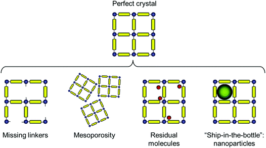
The types of deviations from the perfect structure of IRMOF-1 we consider in this work are summarized in Fig. 1 and include missing linkers, regions of mesoporosity between nano-crystalline regions, the presence of solvent molecules and IRMOF-1 structures loaded with gold nanoclusters. This is, of course, not an exhaustive list of all possible deviations of the structure from the perfect crystal (and, likely, we do not know yet all possible types of defects that can exist in MOFs). For example we do not consider systems with post-synthetic modification of the linkers23 or so called multivariate MOFs,24 while not all of the scenarios considered here are directly relevant for IRMOF-1. This will be further commented on as we present the individual cases.Before we consider structural features and adsorption behaviour of these modified IRMOF-1 structures, it is important to establish the behaviour of the reference, perfect crystal.
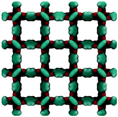
Fig. 2 shows the molecular visualization of the IRMOF-1 crystal (2 × 2 × 2 unit cells). The structure consists of two alternating cages of about 11.37 ± 0.20 Å and 14.62 ± 0.20 Å in diameter, connected by windows of 7.71 ± 0.20 Å (the pore limiting diameter). The accessible surface area is estimated at 3381.49 m2 g−1, which is in good agreement with the experimentally reported values (for example, 3534 m2 g−1 (ref. 25)). Fig. 3 shows adsorption isotherms from molecular simulations and experiments. The experimental data reported by Li et al.7 were also presented in the work of Dubbeldam and co-workers,26 who extensively investigated locations and types of sites available for light gases within IRMOF-1. Here we report the amount adsorbed in the units consistent with those studies.
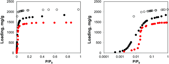 | ||
| Fig. 3 Adsorption isotherms for argon at 78 K in IRMOF-1. Red symbols are the experimental results,7,26 open symbols are unscaled simulation results from Dubbeldam and co-workers,26 black symbols are from molecular simulations in this work. The panel on the right uses the logarithmic pressure scale. | ||
As can be seen from Fig. 3, molecular simulations over-predict the IRMOF-1 capacity for argon. This is consistent with the studies by Dubbeldam and co-workers (although in their work, the simulated capacity was ∼40% higher than in experiments, whereas here it is ∼20% higher than in experiments), who associated this with a portion of the structure being blocked and inaccessible to the adsorbate molecules.26 The differences between the two sets of the simulation results are likely associated with the choice of force field for the framework and argon. On the right side of Fig. 3 we also re-plot the same adsorption isotherm using the logarithmic scale for pressure. The shift of the simulated isotherm to lower values compared to the experiments suggests stronger solid–fluid interactions in the model, compared to the real structure.
Let us now consider the case where some of the linkers are missing in IRMOF-1. Experimentally, there is now a sufficient amount of evidence that MOFs with missing linkers do exist, and moreover can be created on purpose.5,27,28 For example, Zhou and co-workers have prepared variants of the NOTT-101 material with missing linkers, by using a combination of the actual linkers and linker fragments in the synthesis.29 The resulting structures featured a larger pore volume and even mesopores. It then leads to some interesting questions as to how much of the linkers should be removed from the structure to induce mesoporosity, how this threshold depends on the MOF and ligands and whether the resulting structures are mechanically stable. In another example, MOFs based on zirconium and carboxylate linkers are known to feature missing linkers and, in fact, these defects can be induced via modification of the synthetic procedure.27 As has been recently discussed by Cliffe et al., the defects in the UiO-66 structure seem to aggregate in defect-rich regions and these phenomena require some further explanation and understating.30
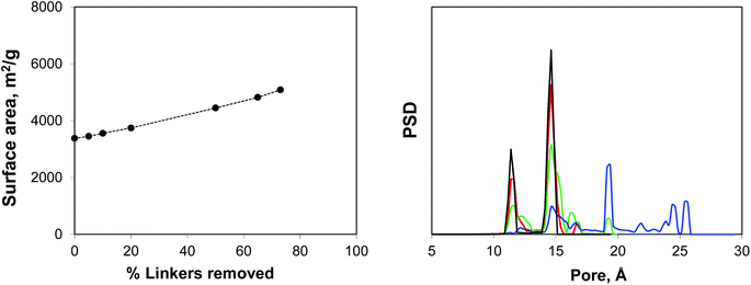
Using IRMOF-1 as a basic model, we consider the effect of the portion of the linkers removed. Here the ligands are removed by cleaving the bonds between the sp2 carbon of the terephthalic acid linker and oxygen atoms. We acknowledge here that from the chemical perspective it is unrealistic and more physically meaningful models can be constructed, including those for the NOTT-101 and UiO-66 materials. Using Poreblazer structure analysis tools,19 we ensure that the remaining structures still form fully supported, percolated clusters. Fig. 4 shows surface areas and geometric pore size distributions (PSDs) as a function of the percentage of linkers removed. Indeed, the surface area (in m2 g−1) steadily increases with the number of linkers removed. The pore size distribution remains almost identical to the perfect crystal with up to 20% of linkers removed (so these PSDs are not shown), however at 50% linkers removed, the PSD starts to develop new peaks, closer to the mesoporous region and at 65% and 73% more of these peaks are added at the positions clearly dictated by the topology of the MOF itself and the characteristic vertex–vertex distances.
Adsorption isotherms in the defected structures in comparison with the reference simulation and experimental results are shown in Fig. 5.
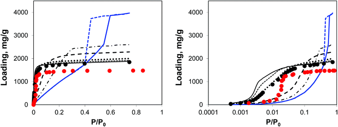 | ||
| Fig. 5 Argon adsorption isotherms at 78 K in IRMOF-1 structures with a progressively larger proportion of linkers removed. Red symbols are the experimental results,7,26 black symbols are from molecular simulations for the perfect crystal. Solid black line is for 5%, short dashed line is for 10%, dotted line is for 20%, long dashed line is for 50%, dotted-dashed line is for 65% and blue line (solid line for adsorption, dashed line for desorption) is for 73% of linkers removed, respectively. The panel on the right plots the same data, using the logarithmic pressure scale. | ||
A small number of linkers removed (5%, 10%, and 20% solid line, short dashed, and dotted lines, respectively) lead to essentially the same simulated isotherm as for the perfect crystal with slightly larger capacity and stronger interactions in the low pressure regime. This is particularly evident in the case of 20% of linkers removed. The real change becomes more visible at 50% of linkers removed (long dashed line) with the isotherm levelling at a much greater loading value and featuring a much less steep initial slope of the isotherm due to the weakened solid–fluid interactions. This trend continues for 65% of linkers removed, however no signs of capillary condensation or hysteresis behaviour are yet observed. At 73% of linkers removed, the isotherm has a completely different shape, corresponding to an intermediate case between Type IV and V isotherms and featuring a hysteresis loop, associated with the presence of mesopores as observed from the PSD. This is similar to the mesoporosity emerging in NOTT-101 as a result of incorporation of incomplete linkers, as reported by Park et al.29 However, Park and co-workers did not observe such a dramatic impact on the initial slope of the isotherms as in the simulations here, suggesting that in their materials mesopores form in between reasonably intact microporous domains. We will consider an alternative model capturing this situation.
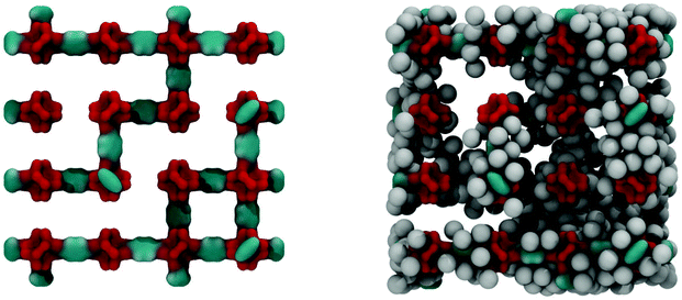
Fig. 6 shows the IRMOF-1 structure with 73% of linkers removed and the same structure with argon molecules adsorbed right before the capillary condensation step.
There are other possible scenarios of how mesoporosity can occur or introduced into a MOF structure. For example, Choi et al. showed that the synthesis of IRMOF-1 in the presence of carefully controlled amounts of 4-(dodecyloxy)bezoic acid (DBA) leads to a sponge-like structure, with pores of 10 nm–100 nm incorporated into the crystalline structure of IRMOF-1, as evidenced from scanning electron microscopy (SEM) and powder X-ray diffraction (PXRD) analysis.31 Interestingly, characterization via nitrogen adsorption at 77 K produced adsorption isotherms of Type I for sponge structures, very similar in shape to the isotherm for the reference microcrystalline IRMOF-1, but with a lower capacity for nitrogen. Mesoporous materials would be expected to have a Type IV or V adsorption isotherm with a characteristic hysteresis loop.32 At least in the case of one of the sponge-like materials, the authors offered an interpretation of these results, whereas liquid-like nitrogen in micropores blocks access to the large interior cavities. We believe that other alternative explanations are also possible: the interior cavities may not be fully evacuated (which would explain the lower capacity for nitrogen) and the pores are too large in size (in the macroporous region) and therefore condensation takes place very close to P/P0 = 1 to lead to a proper Type IV adsorption isotherm.
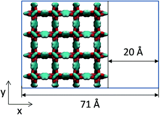
Molecular simulations can help in interpreting this type of experimental work by constructing hypothetical models of mesoporosity in MOFs and exploring their behaviour. Here, we investigate just one variant of the model of this type, where a single mesopore of 20 Å in size is introduced into the microcrystalline structure of IRMOF-1. For this we consider sheets of the IRMOF-1 crystal of two unit cells wide (51.338 Å) separated by a 20 Å gap in the x direction, as schematically depicted in Fig. 7. In the x direction, the crystal is cut between the sp2 carbons and aromatic rings and exposed sp2 carbon atoms are capped with hydrogen atoms to preserve correct valence.
Adsorption behaviour of this system is shown in Fig. 8 in comparison with the perfect crystal, experimental data and the mesoporous system obtained by removing 73% of linkers.
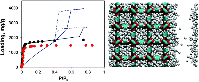 | ||
| Fig. 8 On the left, adsorption isotherms for argon at 78 K in IRMOF-1. Red symbols are the experimental results,7,26 black symbols are from molecular simulations for the perfect crystal. Solid and dashed blue lines are adsorption and desorption isotherms, respectively, for the IRMOF-1 structure with 73% of linkers removed. Solid and dashed black lines are for adsorption and desorption isotherms, respectively, in the structure with a 20 Å mesopore. On the right side, computer visualization of the state of the system preceding the capillary condensation step. The colour scheme is as before. Argon particles are scaled down in size for better visualization. | ||
Indeed, the presence of a single mesopore induces the formation of a hysteresis loop (with the system behaving essentially as a slit pore with complex walls). This isotherm can be classified as Type IV and it is quite different from the isotherm obtained via removal of a large number of linkers: as expected at lower pressures its behaviour essentially retraces the microporous behaviour of the pristine IRMOF-1, with the contribution of the mesopore switched on at a higher pressure. For the system based on the removed linkers, it is the very structure of the microporous IRMOF-1 that has been substantially altered, leading to the weak solid–fluid interactions and large porosity. In fact, the model featuring a single mesopore seems to reflect more closely a situation where defects induced by missing linkers also aggregate, with the resulting pores coalescing into larger mesopores. From this perspective, the isotherm reported in Fig. 8 for the model with 20 Å mesopores is qualitatively much closer to the results of Park et al.29 which serves as indirect evidence of the defect aggregation.
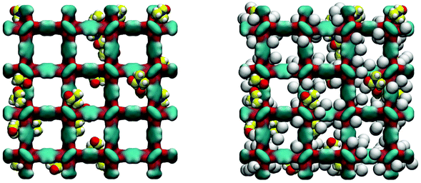
Loading MOFs with guest molecules has been considered as an attractive route to create new, emergent properties for catalysis, sensing and other applications.33 Aside from modifying MOF properties in this way on purpose, the residual solvent and building components will also change adsorption and other properties of a MOF structure, compared to a fully evacuated, perfect crystal. The influence of guest solvent molecules on the adsorption properties of IRMOFs (and in particular on the adsorption of carbon dioxide at 298 K) has been previously studied by Bae and co-workers.34 They argued, based on the results of the thermogravimetric analysis (TGA), that about 3.5 wt% of the solvent remained in the variant of IRMOF-16 they investigated after evacuation. In our system, this corresponds to about 3 DMF molecules per unit cell of IRMOF-1. Here we investigate the adsorption of argon at 78 K in the IRMOF-1 system containing residual DMF molecules. The ESI† provides structural characteristics of these systems, such as surface area and porosity. Firstly, as can be seen in Fig. 9, DMF prefers to occupy energetically favourable locations in the corner of the structure.
As can be seen from the adsorption isotherms, the presence of residual solvent molecules reduces the volume of the system; it also reduces slightly the accessible surface area and pore limiting diameter (see ESI†). At low pressures, although DMF occupies energetically favourable positions that otherwise would be occupied by argon molecules, overall it provides an additional contribution to the adsorption energy, shifting the isotherm to lower pressures, compared to the reference ideal crystal case (Fig. 10).
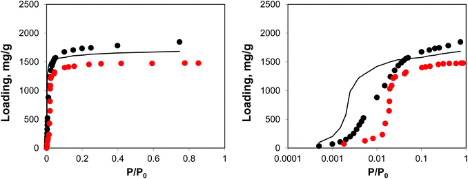 | ||
| Fig. 10 Adsorption isotherms for argon at 78 K in IRMOF-1. Red symbols are the experimental results,7,26 black symbols are from molecular simulations, black line corresponds to the system with residual DMF. The panel on the right uses the logarithmic pressure scale. | ||
A natural extension of this approach would be to consider the influence of the residual amounts of other synthetic components, such as terephthalic acid, on adsorption and structural characteristics. It is plausible that the presence of these components and partially assembled fragments indeed blocks some of the regions of the structure and is behind the differences between the experimental and simulation adsorption behaviour.
Finally, we consider a system where the IRMOF-1 structure is doped with several gold nanoclusters. This system belongs to a wider class of MOF structures, where some guest species or objects (nanoparticles, proteins etc.) are intentionally trapped inside the cages using either “ship-in-the-bottle” or “ship-around-the-bottle” synthetic strategies (see for example ref. 35–38). These systems can lead to new catalytic and sensing devices with exquisite control of the accessibility of binding species to the catalytic site or surface, while improving the stability of the system due to encapsulation.
For example, in the first article on metal nanoparticles encapsulated in MOFs, Hermes et al. used the chemical vapour deposition technique (“ship-in-the-bottle”) to prepare copper, palladium and gold nanoparticles inside IRMOF-1.39 In the case of palladium nanoparticles, their size was around 1.4 nm, while the structure of MOFs has been confirmed to be intact from the X-ray analysis and N2 sorption experiments. Elemental analysis showed 35.6 wt% metal loading in the structure. In the case of gold nanoparticles, TEM and PXRD data indicated polydispersed gold nanoparticles of a much larger size (5–20 nm) at a higher metal loading (48 wt%). It is possible that the gold clusters were forming larger aggregates in these systems across the several cavities. Since this pioneering work, a substantial number of further studies have emerged; however some of the fundamental issues associated with the location, distribution, mobility and accessibility of nanoparticles inside the MOF structure remain to be addressed.35
Recently, Vilhelmsen and co-workers employed quantum-mechanical Density Functional Theory (DFT) to understand the structure and mobility of gold and palladium clusters (Au8, Pd8 and Au4Pd4) in MOF-74. One of the key challenges encountered by the authors is the large number of possible stable geometries of the adsorbed clusters, which depend on the local environment. For example, it was observed that the structure of the gold cluster in the vicinity of the open metal (zinc) site in MOF-74 is quite different from the most stable structure in the vicinity of the aromatic rings or in the gas phase (on the contrary, the most stable structure of the Au8 cluster near the rings is similar to the most stable gas phase structure). Among the other important observations was the much stronger adsorption energy for palladium atoms and clusters compared to the gold atoms and clusters. In combination with the analysis of the diffusion barriers, indicating much lower mobility for palladium clusters, this could explain the metal cluster growth and aggregation processes within MOF hosts.
Here we consider a specific case of a small cluster of 13 atoms of gold in fcc arrangement, previously investigated by Zhang et al.40, using quantum-mechanical density functional theory, in the context of nanoparticles binding to a DNA base. The cluster has a diameter of about 8.36 Å, which is slightly smaller than the smallest size of nanoclusters typically reported in experiments (∼1 nm). In this work we treat the cluster as a rigid structure, independent of the environment, which given the results of Vilhelmsen and co-workers is a drastic oversimplification. Several factors may nevertheless somewhat justify this approach as a starting point. Specifically, the most significant deviations of the metal clusters from their stable gas-phase geometries were observed in the vicinity of open metal sites, which are not present in IRMOF-1. In the case of adsorption to the locations not involving open metal sites, the deviations from the stable gas-phase geometry were also more significant for the palladium containing clusters. Finally, in the process of translocation along the channel of the MOF-74 structure, the geometry of the gold cluster did not change significantly.
Although the size of this nanocluster is slightly larger than the pore limiting diameter in IRMOF-1 (7.71 ± 0.20 Å) the free energy analysis indicates a barrier of only about 7 kJ mol−1 for this nanocluster to cross the window between two cages of IRMOF-1. Molecular dynamics simulations of 5 clusters in a 2 × 2 × 2 system at 300 K (see details in the ESI†) also confirm this picture: nanoclusters do spend some time in the cages, but on the modest timescale of our simulation (total 2 ns) they cross the windows between cages several times. The self-diffusion coefficient of gold nanoclusters is estimated at about 0.18 × 10⁻⁸ m2 s−1 at 300 K, which is comparable to the self-diffusion coefficient values in IRMOF-1 for smaller species such as cyclohexane.41 This may indicate that nanoclusters in this work are too small to be properly trapped inside IRMOF-1, however a much more plausible explanation is associated with the deficiency of the employed classical force field. Indeed the lowest adsorption energy observed in this study (−18 kJ mol−1) is about five times smaller than that observed for the Au8 cluster binding to the locations not containing open metal sites in the studies of Vilhelmsen and co-workers (about −98 kJ mol−1). Similar difference in the magnitude is also observed for the energy barriers. This indicates that the current classical force field (UFF) significantly underestimates the strength of the interaction between metal clusters and structural elements of MOFs. We will return to the developmental needs in the field in the Discussion section.
Five nanoclusters (of 13 atoms each) per eight unit cell of IRMOF-1 correspond to 26 wt% metal loading. From structural analysis, the presence of nanoclusters leads to a slightly reduced surface area and reduced volume by ∼30% (see the ESI†).
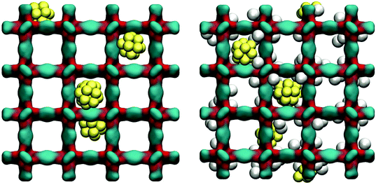
As can be seen from Fig. 11, at 78 K gold nanoclusters position themselves slightly off-centre of the larger cages, attracted by the linkers. This however does not prevent argon molecules from occupying attractive adsorption sites in the very corner of the cages. Whether this is associated with some displacement of the nanoclusters requires further investigation.
Adsorption behaviour of this system is shown in Fig. 12, using both normal and logarithmic scales for pressure.
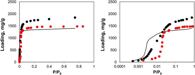 | ||
| Fig. 12 Adsorption isotherms for argon at 78 K. Red symbols are the experimental results,7,26 black symbols are from molecular simulations, black line corresponds to the system loaded with gold nanoclusters. The panel on the right uses the logarithmic pressure scale. | ||
This behaviour is similar to the system with residual DMF molecules: the volume of the system is reduced, while the adsorption isotherm is shifted to lower pressures due to the additional interactions resulting from the presence of guest objects. The degree of volume reduction is however greater in the case of gold nanoclusters.
Discussion
Let us recap the main ideas introduced in this article. Understanding the relationship between the presence of structural defects in MOFs and the resulting properties of MOFs is important for both the development of higher quality, robust crystals and for harvesting new functionalities from these defects. It is difficult to address this problem via experiments only as the very detection and classification of defects is challenging, with several types of defects often present simultaneously in the material.Thus, experimental efforts must be complemented by molecular simulations and theoretical approaches. Firstly, it is only in molecular simulations where properties of a truly ideal crystal can be obtained, as all real crystals contain defects to some extent. Secondly, within the molecular simulations we can probe a hypothesis on the existence of a particular type of defect and structural disorder by constructing a model featuring this defect and exploring the properties of the resulting structure in comparison with the reference ideal crystal.
The purpose of this article was to illustrate how these models can be constructed using IRMOF-1 as a case study. Specifically, we investigated variants of IRMOF-1 with some of the linkers missing and featuring mesopores. We also considered closely related systems where structural disorder comes from some residual molecules present, or from the encapsulated nanoparticles. The power of molecular simulation comes in the ability to decouple the role of different defects and study their impact in isolation. We focused only on two properties: geometric characteristics of the resulting MOFs and adsorption of argon at cryogenic temperatures.
In particular, these studies show that a structure with as much as 20% of linkers removed can be almost indistinguishable from the ideal structure, as probed by the physical adsorption characterization. However, we expect the mechanical and chemical stability of the structure substantially affected by such a concentration of defects. We further show that the shape of the isotherms in the systems featuring mesopores depends substantially on the origin and organization of mesoporosity. Models of this kind can be used to explain the recent experimental observations in the systems with sponge-like meso- and macropores. Finally, molecular simulations of the systems featuring additional guest species show the expected decrease in the pore volume (and hence the capacity), however they also provide a wealth of information on the location and mobility of the guest species and on their interactions with the host structure.
This study also highlights the current profound limitations of the classical force fields and simulations. It seems that almost all interesting problems associated with the presence of the defects and inclusions in MOFs require some quantum-mechanical level of description! Indeed, it has been shown that classical potentials and “off-the-shelf” parameters are not able to accurately describe the interactions between guest gas molecules and open metal-sites in MOFs.42–45 Therefore, defects in MOFs, which lead to (greater) exposure of metal atoms, will also need a quantum-mechanical description and the corresponding calibration of the classical potentials. Current classical force fields are not adequate to describe the mechanical stability and elastic properties of MOFs (at least, without extensive additional optimization of the parameters), and these problems have been tackled recently using a range of quantum-mechanical tools.46,47 Thus, mechanics of MOFs with defects and guest molecules will also require quantum-mechanical methods. The need for accurate quantum-mechanical approaches to assess the structure and mobility of metal nanoclusters trapped inside MOFs has already been illustrated by Vilhelmsen and co-workers.48,49 Finally, the whole spectrum of problems associated with the catalysis in MOFs, i.e. breaking and making bonds, again invokes quantum-mechanical methods as the main investigative tool. We are just at the beginning of this new research field and there is a clear need for more extensive and systematic quantum-mechanical exploration of these systems and for the development of accurate, computationally efficient hybrid methods.
Acknowledgements
The author would like to thank Dr David Dubbeldam for the reference adsorption data for argon in IRMOF-1 at 78 K.Notes and references
- H. Furukawa, K. E. Cordova, M. O'Keeffe and O. M. Yaghi, Science, 2013, 341 CrossRef CAS PubMed , 1230444.
- H. Furukawa, N. Ko, Y. B. Go, N. Aratani, S. B. Choi, E. Choi, A. O. Yazaydin, R. Q. Snurr, M. O'Keeffe, J. Kim and O. M. Yaghi, Science, 2010, 329, 424–428 CrossRef CAS PubMed.
- G. Ferey and C. Serre, Chem. Soc. Rev., 2009, 38, 1380–1399 RSC.
- C. E. Wilmer, M. Leaf, C. Y. Lee, O. K. Farha, B. G. Hauser, J. T. Hupp and R. Q. Snurr, Nat. Chem., 2011, 4, 83–89 CrossRef PubMed.
- Z. Fang, B. Bueken, D. E. De Vos and R. A. Fischer, Angew. Chem., Int. Ed., 2015, 54, 7234–7254 CrossRef CAS PubMed.
- D. S. Sholl and R. P. Lively, J. Phys. Chem. Lett., 2015, 6, 3437–3444 CrossRef CAS PubMed.
- H. Li, M. Eddaoudi, M. O'Keeffe and O. M. Yaghi, Nature, 1999, 402, 276–279 CrossRef CAS.
- A. Gupta, S. Chempath, M. J. Sanborn, L. A. Clark and R. Q. Snurr, Mol. Simul., 2003, 29, 29–46 CrossRef CAS.
- A. K. Rappe, C. J. Casewit, K. S. Colwell, W. A. Goddard and W. M. Skiff, J. Am. Chem. Soc., 1992, 114, 10024–10035 CrossRef CAS.
- A. O. Yazaydin, R. Q. Snurr, T. H. Park, K. Koh, J. Liu, M. D. LeVan, A. I. Benin, P. Jakubczak, M. Lanuza, D. B. Galloway, J. J. Low and R. R. Willis, J. Am. Chem. Soc., 2009, 131, 18198–18199 CrossRef CAS PubMed.
- C. T. Lee, W. T. Yang and R. G. Parr, Phys. Rev. B: Condens. Matter, 1988, 37, 785–789 CrossRef CAS.
- A. D. Becke, J. Chem. Phys., 1993, 98, 5648–5652 CrossRef CAS.
- P. J. Stephens, F. J. Devlin, C. F. Chabalowski and M. J. Frisch, J. Phys. Chem., 1994, 98, 11623–11627 CrossRef CAS.
- C. M. Breneman and K. B. Wiberg, J. Comput. Chem., 1990, 11, 361–373 CrossRef CAS.
- M. J. Frisch, G. W. Trucks, H. B. Schlegel, G. E. Scuseria, M. A. Robb, J. R. Cheeseman, G. Scalmani, V. Barone, B. Mennucci and G. A. Peterssonet al., Gaussian09, Revision A.1, Gaussian, Inc., Wallingford CT, 2009 Search PubMed.
- C. J. Fennell and J. D. Gezelter, J. Chem. Phys., 2006, 124 CrossRef CAS PubMed , 234104.
- P. P. Ewald, Ann. Phys., 1921, 369, 253–287 CrossRef.
- J. K. Johnson, J. A. Zollweg and K. E. Gubbins, Mol. Phys., 1993, 78, 591–618 CrossRef CAS.
- L. Sarkisov and A. Harrison, Mol. Simul., 2011, 37, 1248–1257 CrossRef CAS.
- L. Sarkisov, J. Phys. Chem. C, 2012, 116, 3025–3033 CAS.
- L. Sarkisov, Phys. Chem. Chem. Phys., 2012, 14, 15438–15444 RSC.
- D. Dubbeldam, H. Frost, K. S. Walton and R. Q. Snurr, Fluid Phase Equilib., 2007, 261, 152–161 CrossRef CAS.
- K. K. Tanabe and S. M. Cohen, Chem. Soc. Rev., 2010, 40, 498–519 RSC.
- H. Deng, C. J. Doonan, H. Furukawa, R. B. Ferreira, J. Towne, C. B. Knobler, B. Wang and O. M. Yaghi, Science, 2010, 327, 846–850 CrossRef CAS PubMed.
- A. G. Wong-Foy, A. J. Matzger and O. M. Yaghi, J. Am. Chem. Soc., 2006, 128, 3494–3495 CrossRef CAS PubMed.
- D. Dubbeldam, H. Frost, K. S. Walton and R. Q. Snurr, Fluid Phase Equilib., 2007, 261, 152–161 CrossRef CAS.
- H. Wu, Y. S. Chua, V. Krungleviciute, M. Tyagi, P. Chen, T. Yildirim and W. Zhou, J. Am. Chem. Soc., 2013, 135, 10525–10532 CrossRef CAS PubMed.
- C. V. McGuire and R. S. Forgan, Chem. Commun., 2015, 51, 5199–5217 RSC.
- J. Park, Z. U. Wang, L.-B. Sun, Y.-P. Chen and H.-C. Zhou, J. Am. Chem. Soc., 2012, 134, 20110–20116 CrossRef CAS PubMed.
- M. J. Cliffe, W. Wan, X. Zou, P. A. Chater, A. K. Kleppe, M. G. Tucker, H. Wilhelm, N. P. Funnell, F.-X. Coudert and A. L. Goodwin, Nat. Commun., 2014, 5 CAS , 4176.
- K. M. Choi, H. J. Jeon, J. K. Kang and O. M. Yaghi, J. Am. Chem. Soc., 2011, 133, 11920–11923 CrossRef CAS PubMed.
- M. Thommes, Chem. Ing. Tech., 2010, 82, 1059–1073 CrossRef CAS.
- M. D. Allendorf, M. E. Foster, F. Léonard, V. Stavila, P. L. Feng, F. P. Doty, K. Leong, E. Y. Ma, S. R. Johnston and A. A. Talin, J. Phys. Chem. Lett., 2015, 6, 1182–1195 CrossRef CAS PubMed.
- Y. S. Bae, D. Dubbeldam, A. Nelson, K. S. Walton, J. T. Hupp and R. Q. Snurr, Chem. Mater., 2009, 21, 4768–4777 CrossRef CAS.
- M. Meilikhov, K. Yusenko, D. Esken, S. Turner, G. Van Tendeloo and R. A. Fischer, Eur. J. Inorg. Chem., 2010, 2010, 3701–3714 CrossRef.
- J. Juan-Alcañiz, E. V. Ramos-Fernandez, U. Lafont, J. Gascon and F. Kapteijn, J. Catal., 2010, 269, 229–241 CrossRef.
- F. Lyu, Y. Zhang, R. N. Zare, J. Ge and Z. Liu, Nano Lett., 2014, 14, 5761–5765 CrossRef CAS PubMed.
- J. D. Evans, C. J. Sumby and C. J. Doonan, Chem. Soc. Rev., 2014, 43, 5933–5951 RSC.
- S. Hermes, M.-K. Schröter, R. Schmid, L. Khodeir, M. Muhler, A. Tissler, R. W. Fischer and R. A. Fischer, Angew. Chem., Int. Ed., 2005, 44, 6237–6241 Search PubMed.
- X. Zhang, C. Q. Sun and H. Hirao, Phys. Chem. Chem. Phys., 2013, 15, 19284–19292 RSC.
- L. Sarkisov, T. Düren and R. Q. Snurr, Mol. Phys., 2004, 102, 211–221 CrossRef CAS.
- L. J. Chen, L. Grajciar, P. Nachtigall and T. Duren, J. Phys. Chem. C, 2011, 115, 23074–23080 CAS.
- L. J. Chen, C. A. Morrison and T. Duren, J. Phys. Chem. C, 2012, 116, 18899–18909 CAS.
- M. Fischer, J. R. B. Gomes and M. Jorge, Mol. Simul., 2014, 40, 537–556 CrossRef CAS.
- M. Jorge, M. Fischer, J. R. B. Gomes, C. Siquet, J. C. Santos and A. E. Rodrigues, Ind. Eng. Chem. Res., 2014, 53, 15475–15487 CrossRef CAS.
- A. U. Ortiz, A. Boutin, A. H. Fuchs and F. X. Coudert, Phys. Rev. Lett., 2012, 109 CrossRef CAS , 195502.
- L. Chen, J. P. S. Mowat, D. Fairen-Jimenez, C. A. Morrison, S. P. Thompson, P. A. Wright and T. Duren, J. Am. Chem. Soc., 2013, 15763–15773 CrossRef CAS PubMed.
- L. B. Vilhelmsen, K. S. Walton and D. S. Sholl, J. Am. Chem. Soc., 2012, 134, 12807–12816 CrossRef CAS PubMed.
- L. B. Vilhelmsen and D. S. Sholl, J. Phys. Chem. Lett., 2012, 3, 3702–3706 CrossRef CAS PubMed.
Footnote |
| † Electronic supplementary information (ESI) available. See DOI: 10.1039/c5dt03498a |
| This journal is © The Royal Society of Chemistry 2016 |

