Recent advances in metal–nitrogen–carbon catalysts for electrochemical water splitting
Kaihua
Liu
ab,
Haixia
Zhong
a,
Fanlu
Meng
ab,
Xinbo
Zhang
 *a,
Junmin
Yan
*b and
Qing
Jiang
 b
b
aState Key Laboratory of Rare Earth Resource Utilization, Changchun Institute of Applied Chemistry, Chinese Academy of Sciences, Changchun 130022, China. E-mail: xbzhang@ciac.ac.cn; Fax: +86-431-85262235; Tel: +86-4385262235
bKey Laboratory of Automobile Materials, Ministry of Education and College of Materials Science and Engineering, Jilin University, Changchun 130022, China
First published on 24th April 2017
Abstract
The urgent need for clean and renewable energy and environmental awareness have promoted extensive research into creating a future sustainable energy supply system. Water electrolysis, considered the most promising technology for hydrogen production, has attracted much attention. A series of metal–nitrogen–carbon based heterogeneous electrocatalysts have been developed for HER and OER. Recent advances in this field are summarized here, including their structures, synthetic methods and especially highlighting the applications of several major kinds of catalysts in water splitting. Finally, the existing key challenges and research directions for enhancing performance are pointed out.
1. Introduction
With the continuous increase in energy demand and related environmental issues, creating a global-scale sustainable energy system for the future is one of the most crucial challenges.1–4 Hydrogen has been regarded as the future energy carrier due to its highest energy density per mass and pollution-free by-product.5,6 Moreover, among the current main pathways for industrial hydrogen production,7 water electrolysis, preferably coupled with renewable energy resources, is considered the most promising technology for hydrogen production, which is consistent with future sustainable energy supply, as its feedstock, water, is an abundant and renewable hydrogen source.8–10 Electrochemical water splitting can be divided into two half-reactions: the hydrogen evolution reaction (HER) and the oxygen evolution reaction (OER) on the cathode and anode, respectively. Although this technology can meet our various harsh requirements, the influence of many factors means it suffers from high cost and low energetic efficiency.11–13 Thus, seeking efficient catalysts to drastically accelerate the reaction and improve the efficiency in a moderate manner are highly desirable in addition to continuous technological improvement.Currently, the state-of-the-art HER and OER catalysts are Pt-group metals and Ir- or Ru-based compounds, respectively,14,15 but their long-term availability is questionable because of their scarcity and subsequent prohibitive price, as well as their limited stability.16,17 Therefore, substantial efforts have been devoted to developing non-noble metal electrocatalysts with commensurate performance, and a series of robust catalysts have been well established for either HER18–22 or OER.23–26 Among these, metal–nitrogen–carbon (M–N–C) materials, which have emerged as the most promising oxygen reduction catalysts,27–31 have also gained increasing research interest for water splitting due to their unique properties. Obviously, their high activity mainly depends on the special atomic structures of M–N–C catalysts because of the strong dependency between structure and property. For instance, multi-shelled hollow structures have been extensively synthesized and have achieved high performance in many fields.32–41 However, relevant reviews about M–N–C structures and their applications in water splitting have still not been published.
In view of the rapid development of this thriving field, a comprehensive review may guide further scientific activities. Herein, we summarize recent progress in M–N–C heterogeneous water-splitting electrocatalysts, including Co–N–C, Ni–N–C, Fe–N–C, alloy–N–C and others. The M–N–C structures and the frequently used synthetic strategies will be introduced first. Then these catalysts for water splitting are described. Last, some scientific challenges that exist in M–N–C heterogeneous catalysts and the outlook for future research are also discussed.
2. Evaluation parameters and M–N–C structure
2.1 Evaluation parameters
To estimate the catalytic activity of target electrocatalysts, some frequently-used parameters should be provided, mainly including overpotential, Tafel slope and exchange current density, turnover frequency, faradaic efficiency, as well as stability. As they have been illustrated comprehensively in many other reviews,7,42–44 here we explain them briefly.Firstly, regardless of the media where water splitting takes place, the thermodynamic voltage of water splitting is 1.23 V under standard conditions, but actually a larger potential is needed to push electrochemical water splitting, wherein the excess potential compared to the theoretical potential is the overpotential. The potential at which water splitting occurs is the onset potential. However, in most cases, the overpotential needed to reach a current density of 10 mA cm−2 is often used to compare the catalytic activity of catalysts, and this is the metric relevant to solar fuel synthesis. Next, the Tafel slope and exchange current density which are two important kinetic parameters can be obtained from the Tafel equation. The possible rate-determining reaction mechanism of the catalyst can be deduced from the Tafel slope, and the exchange current density is correlated to the intrinsic catalytic activity of the electrode material under equilibrium conditions. In brief, an efficient electrocatalyst usually possesses a low overpotential, small Tafel slope and high exchange current density. In addition, the catalytic activity of an individual active site can be deduced from the turnover frequency, which is defined as the number of reactants that a catalyst can convert to a desired product per catalytic site per unit of time. However, it is always difficult to garner the precise turnover frequency, as the heterogeneously electrocatalytic reaction always occurs at the surface of the electrode. As for the faradaic efficiency, it is the ratio between the experimental and theoretical hydrogen production. Thus, the theoretical production can be calculated from galvanostatic or potentiostatic electrolysis and the practical production can be obtained by gas chromatography. Most of the faradaic loss originates mainly from heat loss or the formation of other products. Stability is another critical parameter for practical applications, and it can be characterized by two simple electrochemical techniques: cyclic voltammetry and galvanostatic/potentiostatic electrolysis. Generally, stable catalysts should offer a current density larger than 10 mA cm−2 for more than 10 h or over 5000 cyclic voltammetry cycles.
2.2 M–N–C structure
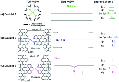
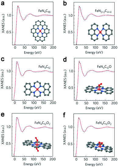
Initial research into M–N–C complexes can be traced back to 1964 when it was found that Co–phthalocyanine exhibited oxygen reduction activity.45 Since then, numerous efficient M–N–C catalysts, based on different research directions, such as synthetic methods and mechanistic study, have been widely discussed.46–49 However, the active site structure and catalytic mechanism of these M–N–C catalysts are still hard to illustrate clearly.50 Possible reasons may be that the non-crystallographic ordering of the metal atoms is difficult to confirm, as well as the disturbance of the simultaneous presence of other metal-based phases. However, poisoning of M–N–C catalysts by cyanide indicated the metal-based nature of the activity.51 Generally, the catalytic activity sites of M–N–C catalysts are the M–Nx and N defects. Based on previous studies, some molecular structures have been proposed. For instance, in the case of Fe–N–C catalysts, the FeN4 species were detected by Time of Flight Secondary Ion Mass Spectrometry.52 And then, several Fe–Nx species have also been proposed based on Extended X-ray Absorption Fine Structure (EXAFS) and Mössbauer spectroscopies, as shown in Fig. 1.53 Briefly, three doublets, the ferrous ions in a low (D1), intermediate (D2) or high (D3) spin state, were assigned to molecular FeN4-like sites, and two other doublets (D4 and D5) were assigned to surface oxidized nanoparticles of iron nitride (FexN, x ≤ 2.1). In addition, another Fe-species, attributed to incomplete FeN4-like sites, appears only in the catalysts with Fe-contents ≥0.27 wt%, which can quickly dissolve in contact with an acid. Thus, most of D2, D4 and D5 can be also removed after acid washing of the original Fe–N–C catalysts, but the D1 and D3 are much more acid-resistant.Recently, Zitolo et al. investigated the structure of active sites in Fe–N–C catalysts which were pyrolysed in Ar or NH3.54 The EXAFS result indicated that the best-fit analysis was 5-fold and 6-fold coordination (Fig. 2). While the results of X-ray absorption near-edge spectroscopy (XANES) spectra, reported in Fig. 3, displayed an excellent agreement between experimental and theoretical spectra. Thus, the structure of two candidate active sites having a porphyrinic planar architecture with an FeN4C12 core and with dioxygen adsorbed in the side-on or end-on configuration was provided, which was in strong contrast with the previously assumed FeNxCy moieties based on N atoms included in six membered rings. Even though other FeNxCy moieties may be present in other systems, important constraints limiting the remaining degrees of freedom were also proposed. First, the coordination number of Fe with a light atom (C, N or O) is 5–6 in the first coordination sphere, while in the second coordination sphere it is larger than 10, thus demanding that the C–N–C bond angles should be smaller than 120°. Subsequently, the absence of the pre-edge peak needs axial ligands breaking the D4h symmetry. This is a major step towards an understanding of the Fe–N–C structure.
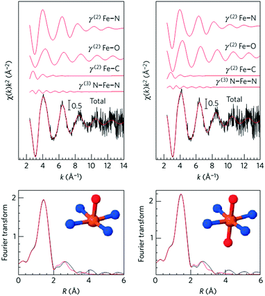 | ||
| Fig. 2 Fe K-edge EXAFS analysis of Fe0.5 with an FeN4 moiety having one (left) or two (right) oxygen atoms in the axial direction. | ||
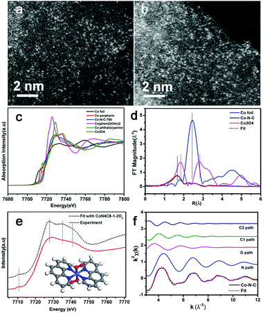
Very recently, Zhang et al. synthesized a single-atom dispersed Co–N–C catalyst.55 Since Co was dispersed exclusively as single atoms, the structure of this Co–N–C was identified to be CoN4C8-1-2O2, where the Co center atom was coordinated with four pyridinic N atoms in the graphitic layer, while two oxygen molecules were weakly adsorbed onto Co atoms perpendicular to the Co–N4 plane. This was shown by means of sub-Ångström-resolution high-angle annular dark field aberration-corrected scanning transmission electron microscopy (HAADF-STEM) in combination with XANES and EXAFS analysis, as shown in Fig. 4. Based on these considerations, the M–N–C structure might be related to many factors, such as the synthesis process, so the exact nature of the M–N–C structures is still being debated.
3. Synthetic strategies
The most common method to fabricate M–N–C nanostructures is heat-treatment of the related precursors. According to the different precursors, the methods can be divided into two categories. One is the pyrolysis of metal macrocycles complexes, and another is the preparation by direct pyrolysis of a mixture of metal salts, N- and C-containing precursors.3.1 Pyrolysis of metal macrocycles complexes
Typically, ideal M–N–C catalysts always possess a large number of M–N4 sites in the carbonaceous matrix and a minimum number of metal nanoparticles. In addition, the carbon supports, which can affect the mass transportation, active site distributions and overall conductivity, also play a critical role in the catalytic reaction.56 Originally, heat-treatment of the transition metal macrocycles has always been carried out to synthesize M–N–C catalysts, such as Fe and Co porphyrins or phthalocyanines. For instance, the feasibility of heat-treated carbon-supported Co tetramethoxyphenylporphyrin (CoTMPP), a typical macrocycle, was investigated,57 and then Zhang et al. adopted ultrasonic spray pyrolysis to synthesize spherical and porous carbon-supported CoTMPP catalysts,58 which exhibited a specific surface area which was twice as large as that of the conventional sample.3.2 Pyrolysis of mixtures of M-, N- and C-precursors
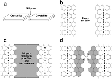
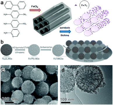
Another synthesis method to prepare M–N–C catalysts is direct pyrolysis of a mixture of related metal salts, N- and C-containing precursors. And based on the different N sources, they can be divided into inorganic N sources and organic N sources.In general, the intrinsic advantages of mesoporous materials, such as mesopores and high specific surface areas, are beneficial for high-flux mass transportation and efficient utilization of active catalytic sites. So porous M–N–C materials were often prepared and generally used in the template-assisted synthesis route. For example, ordered hierarchically porous Fe–N-embedded graphitic architectures were synthesized by pyrolysis of 2,2-bipyridine and Fe salt in confined mesochannels of SBA-15, and then etching of the templates (Fig. 6a).66 This preparation method can produce an in situ-formed carbon matrix with a uniform distribution of catalytically active sites on the complete surface. However, the template removed is trivial, time-consuming and uses dangerous acids or alkalis. In this context, our group fabricated Fe–N–mesoporous carbon microspheres via carbonization of Fe-modified polypyrrole mesoporous microspheres, wherein the Fe3O4 mesoporous microspheres were simultaneously employed as the mesoporous structure directing agent, the source of Fe3+ ions which is the oxidation agent for the polymerization of pyrrole, and the Fe precursor (Fig. 6b).67 Finally, a porous structure with a homogeneous Fe and N species distribution was obtained by this facile in situ replication and polymerization strategy (Fig. 6c and d).
In addition, considering their elemental composition and structural advantages, metal–organic frameworks (MOFs), which inherently possess metal, N– and C– in the backbone, an ordered structure, higher surface area and tunable porosity, are no doubt the ideal precursors to fabricate efficient M–N–C catalysts.50,56,68 Importantly, M–N–C catalysts can be derived from direct calcination of the relevant MOF precursors, especially for Fe–N–C and Co–N–C. Thus, calcining MOFs to obtain M–N–C composites has been widely used.69–71
3.3 Other synthetic methods
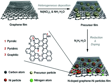
Though the above pyrolysis methods can directly obtain M–N–C catalysts, there are also many questions, such as the reproducibility and precise composition control. Therefore, a search for facile and high-temperature free synthesis methods should be considered. As shown in Fig. 7, the Qiao group prepared N-doped graphene film-confined Ni nanoparticles by a heterogeneous reaction process.72 First, the graphene film was impregnated with Ni(NO3)2 and NH3·H2O, and then heated to obtain the precursor film. Subsequently, the precursor film was doped and reduced via the solvothermal reaction with N2H4·H2O. Searching for diversified synthetic strategies to construct various special structures still plays a crucial role in their practical application.4. Applications of M–N–C catalysts in water splitting
Compared with the extensive study of M–N–C catalysts in oxygen reduction, recently the application of M–N–C materials in water splitting has attracted broad interest, and some progress has been achieved. Considering the synthetic process and elemental composition, the presence of some metals, such as Co and Fe, can catalyze the formation of N–C nanostructures, such as CNTs. Thus, metal embedding, N doping and their synergistic effect, which can regulate the H-bonding energy and electrical conductivity, all contribute to improving the electrocatalytic performance. Furthermore, in most cases, the metal is protected by the carbon layers, which is beneficial for avoiding corrosion and oxidization and preventing agglomeration, as well as for the stability of the catalysts. Accordingly, M–N–C composites may be promising water splitting electrocatalysts.4.1 Co–N–C materials
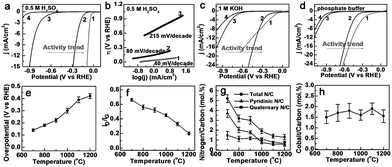
Co–N–C materials have been widely researched for HER73–83 and OER,84–90 as well as for full water splitting catalysts.91–97 Thanks to their structural advantages, Co–N–C complexes can be used as efficient HER catalysts at various pH values. For example, Co nanoparticles encapsulated in a Co and N co-doped carbon catalyst (Co@Co–N–C) displayed an onset potential of 78 mV with a Tafel slope of 59 mV dec−1 in 0.1 M KOH solution.76 While N–C wrapped Co nanoparticles supported on N-doped graphene (Co@NC/NG) showed an onset potential of 49 mV with a Tafel slope of 79.3 mV dec−1 in 0.5 M H2SO4, and theoretical studies implied that the catalytically active sites likely arose from carbon atoms promoted by the entrapped Co nanoparticles.77 Other work also suggested that the transition metals and N played a critical role in the enhanced activity based on results from electrochemical and DFT calculations.81 In addition, most of these types of catalyst can be used as HER catalysts in both alkaline and acidic media,74 and even neutral electrolytes.75,79,82,83Zou et al. first reported CNT-based Co–N–C electrocatalysts (Co–NRCNTs) for HER.75 As shown in Fig. 8a–d, the Co–NRCNTs exhibited high HER activity and stability over the whole pH range. In addition, the origin of the superior HER activity of Co–NRCNTs was also investigated. An increase in the pyrolysis temperature caused the HER activity to decrease, which was consistent with the defect density and N content in the catalysts except for the unchanged Co content (Fig. 8e–h). The influence of metal nanoparticles was revealed based on the catalytic activities (Fe–NRCNTs < Ni–NRCNTs < Co–NRCNTs) which was tested under the same conditions. These results indicated that the embedded Co particles, N dopants, and synergistic effects between them all contributed to the excellent HER activity. Nevertheless, a mechanistic investigation to reveal the real reasons, especially on the atomic level, is still needed.
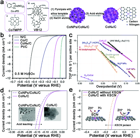
Increasing the surface area to provide more active sites, Liang et al. prepared a porous Co–N–C catalyst with a high specific surface area (1074 m2 g−1) (Fig. 9a).83 Undoubtedly, this catalyst displayed an outstanding HER performance at all pH values, such as 10 mA cm−2 achieved at an overpotential of 133 mV in acid, and unprecedented TOFs (TOFs per Co atom of 0.39 and 6.5 s−1 at an overpotential of 100 and 200 mV, respectively) (Fig. 9b and c). Moreover, thiocyanate ions (SCN−), which can poison the metal-centred catalytic sites in acid, were adopted to demonstrate that the active sites are CoNx centres (Fig. 9d and e). However, as they noted, there is still large room for further improvement in the HER performance of M–N–C catalysts, such as optimizing the M–N binding or increasing the density of MNx sites. Recently, single-atom catalysis has attracted increasing attention because of the lowest size limit to obtain full atom utility, and decreasing the nanoparticle size can also expose more active sites. Thus Co atoms, coordinated to N atoms on graphene, were prepared and exhibited high HER performance in both acidic and basic solutions.98
One novel two-dimensional carbon allotrope, graphdiyne (GD), has attracted much attention due to its special composition of a one-atom thick layer of sp- and sp2-hybridized carbon atoms.99–101 Thanks to its special structure, GD exhibits intriguing properties, such as a unique electronic structure, electrical conductivity, and high chemical stability. Thus, it has been applied in many fields.102–105 Recently, GD nanosheets supporting Co nanoparticles wrapped in N-doped C (CoNC/GD) were fabricated as HER catalysts.106 Impressively, this catalyst displayed superior HER performance and unprecedented durability, which could be indicated by the negligible current change over 36![[thin space (1/6-em)]](https://www.rsc.org/images/entities/char_2009.gif) 000, 38
000, 38![[thin space (1/6-em)]](https://www.rsc.org/images/entities/char_2009.gif) 000, and 9000 cycles under basic, acidic, and neutral conditions, respectively. Finally, the outstanding HER behaviors of CoNC/GD could be explained as follows: (1) the unique electronic structure and high conductivity of the GD nanosheets make them highly conductive supporting matrices. (2) The high porosity of the GD structure ensures efficient mass transport. (3) The Co atoms interacting with the alkyne rings facilitate rapid electron transfer from the Co atoms to the GD sheets. (4) The intimate contacts of the Co atoms with both the GD nanosheets and the N-doped C coatings provide more catalytically active sites and enhance the stability.
000, and 9000 cycles under basic, acidic, and neutral conditions, respectively. Finally, the outstanding HER behaviors of CoNC/GD could be explained as follows: (1) the unique electronic structure and high conductivity of the GD nanosheets make them highly conductive supporting matrices. (2) The high porosity of the GD structure ensures efficient mass transport. (3) The Co atoms interacting with the alkyne rings facilitate rapid electron transfer from the Co atoms to the GD sheets. (4) The intimate contacts of the Co atoms with both the GD nanosheets and the N-doped C coatings provide more catalytically active sites and enhance the stability.
As for the typical interface reaction, activating the outermost carbon layer and engineering the surface active sites are efficient means to improve activity. Thus, Co nanoparticles encapsulated by N and B codoped ultrathin graphitic carbon cages were constructed.73 Surprisingly, the Co@BCN showed extraordinary HER activity with an onset potential of about 0 V, an overpotential of 96 mV to achieve 10 mA cm−2, and a Tafel slope of 63.7 mV dec−1 in 0.5 M H2SO4. In addition, the poisoning test with SCN− revealed that the B, N codoped carbon shell contributed significantly more than a trace of uncoated Co species to the enhanced HER activity, which should be the major active sites in this catalyst. Finally, based on the DFT calculations, the encapsulation of Co nanoparticles by an outer carbon shell modifying the electronic Fermi level, and the codoping of N and B heteroatoms generating additional active sites, produced a synergistic effect to optimize the ΔGH*, and hence improved the HER activity.
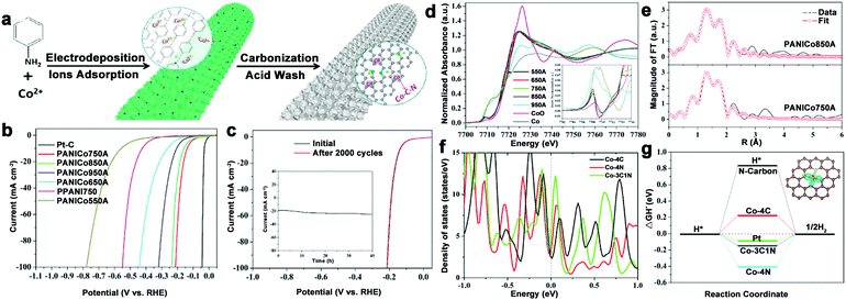
To avoid burying the active sites and low electron contact surface area caused by the insulated polymer binder, and even alleviating the gas accumulations for stabilizing the electrode during electrolysis process, 3D integrated HER electrodes are always actively pursued. N–C coated Co nanorod arrays supported on titanium mesh (Co@NC/Ti) were prepared and showed high activity over a wide pH range.80 To further optimize the electrode structure, our group fabricated a self-supported and 3D porous structure of Co–N–C catalysts (only 0.22 at% Co), which displayed excellent HER performance, especially in acid (212 mV at 100 mA cm−2) and long-term stability (Fig. 10a–c).82 Importantly, the structure of the active sites was investigated by XANES and EXAFS spectroscopy (Fig. 10d–f). The Co K-edge XANES spectra suggested the possible existence of Co–C/N species, and Co–C and Co–N bonds coexisting in the active Co complex were demonstrated by the XAFS results, which also indicated that the total coordination number was five. Then, DFT calculations were performed to investigate the catalytic mechanisms of this complex. As a result, Co–3C1N showed a high density of states crossing the Fermi level, which contributed to electron mobility, and a moderate free energy for H adsorption compared with Co–4C and Co–4N (Fig. 10g). Based on these results, the excellent HER activity was mainly attributed to the synergistic effect of the C and N hybrid. Moreover, considering the preparation of robust catalysts with low metal content, an interconnected Co–NCNT film on CC (Co–NCNT/CC) was designed and showed excellent HER performance and durability over the whole pH range with 10 mA cm−2 achieved at overpotentials of 78, 170, and 180 mV in acidic, neutral and alkaline electrolytes, respectively.78
The Co–N–C complex was also studied with respect to OER, which severely constrained the overall energy efficiency. Co and N codoped graphene with inserted carbon nanospheres was synthesized and showed an overpotential of 426 mV at 10 mA cm−2.85 And then to provide a high specific area and a shorter diffusion distance, a Co–N–C catalyst with hollow tetragonal microstructure was constructed, which exhibited high OER activity and stability with an overpotential of 390 mV at 10 mA cm−2, as well as negligible potential change under 10 h of continuous galvanostatic electrolysis.88 Another strategy to improve the catalytic activity is to decrease the charge transfer resistance.89 In addition, a Co–N–CNT catalyst was also prepared and displayed an overpotential of 300 mV to achieve a current density of 10 mA cm−2 in neutral, and 50 mA cm−2 in alkaline media, respectively.84
The transition-metal oxides always show good OER catalytic activity. Thus, Co@Co3O4 encapsulated in in situ formed N–CNT-grafted carbon polyhedra was fabricated.86 Thanks to the highly graphitic nature of CNT-grafted polyhedra, the introduction of N and Co, and the synergy between conductive metallic Co cores and semiconductive Co3O4 shells which produced a Schottky barrier between them, which is beneficial for charge separation, this catalyst exhibited high OER performance with 10 mA cm−2 at 1.64 V, and excellent durability with no significant loss in activity after 45 h. What is more, this catalyst can be directly grown on Ni foam to construct a 3D integrated OER electrode, which displays a better OER stability with a potential of 1.62 V at 10 mA cm−2.
The above study only focuses on one of the two half reactions without considering full water splitting. The N-doped graphene/Co-embedded porous carbon polyhedron (Co–NC/NRGO) was prepared, and showed superior performance for HER with an onset overpotential of 58 mV and a current density of 10 mA cm−2 at 229 mV in acid media, as well as good catalytic performance for OER in alkaline media with a potential of 1.66 V for 10 mA cm−2.91 However, the activity of HER and OER in the same electrolyte was not discussed. Developing electrocatalysts for both HER and OER in the same electrolyte to achieve efficient overall water splitting is no doubt highly imperative. The Bao group took a further step towards the application of Co–N–C catalysts in overall water splitting. They reported that Co nanoparticles encapsulated in N-doped C (Co@N–C) exhibited high HER activity and durability over a wide pH range, as well as good OER performance in alkaline medium.94 Furthermore, an electrolyzer prototype using Co@N–C as a bifunctional catalyst was built, and displayed considerable activity for water electrolysis at 80 °C (Fig. 11). After that, Co embedded in porous N-rich C (PNC/Co)93 and a Co–N–C complex interlinked by CNTs (Co–NC/CNT)95 were prepared and afforded a water-splitting current of 10 mA cm−2 at cell voltages of 1.64 V and 1.625 V, respectively.
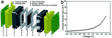 | ||
| Fig. 11 (a) Schematic configuration of a full water electrolyzer. (b) Polarization curves of water electrolyzer using Co@N–C as both cathode and anode catalysts at 80 °C. | ||
Co/Co oxide–N–C composites were also fabricated for overall water splitting.92,97 Considering the superiority of carbon conductivity, the moderate H-bonding energy of metallic Co, and better OER activity of Co oxide, multi-component Co–Co oxide–N-doped carbon hybrids (CoOx@CN) were synthesized.97 And undoubtedly, this hybrid exhibited outstanding HER activity and stability with a small onset overpotential of 85 mV and 10 mA cm−2 achieved at a low overpotential of only 235 mV in 1 M KOH. Impressively, a significantly enhanced OER performance was obtained after a 30 min HER test because of the increase in Co2+. Finally, a water electrolyzer, with CoOx@CN as the cathode and anode electrocatalyst, was constructed, which achieved ∼20 mA cm−2 at a voltage of only 1.55 V. Electrocatalytic experiments further indicated that the extraordinary catalytic performance was mainly attributable to the synergistic effect of Co species, the stability of C-encapsulated Co nanoparticles, the introduction of electron-rich N, and the high conductivity of C.
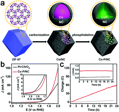
Recently, transition metal phosphides have been reported as efficient multifunctional catalysts for water electrolysis. Thus, a Co–P/N–C hybrid was also prepared for overall water splitting.107,108 Mesoporous Co–P/N–C nanopolyhedrons were synthesized by phosphorization of a Co–N–C complex (Fig. 12a),107 which exhibited superior catalytic activity to a Co–N–C complex with 10 mA cm−2 achieved at an overpotential of 154 mV for HER and 319 mV for OER in 1 M KOH. In addition, this Co–P/N–C based overall water electrolyzer achieved 165 mA cm−2 at 2.0 V, superior to that of a Pt/IrO2 couple, as well as strong stability (Fig. 12b and c). The 3D interconnected mesoporosity, and the CoPx encapsulated within N-doped C matrices which can be partially oxidized to CoOx, and are thus beneficial for OER activity, synergistically promote the overall catalytic performance of Co–P/N–C for water electrolysis. A 3D integrated electrode of Co–N–C, followed by phosphorization, was also prepared.108 However, the activity is still far from satisfactory.
4.2 Ni–N–C materials
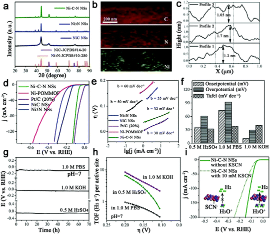
With the second highest abundance and lowest price after Fe, metal Ni-based catalysts show the great potential for water electrolysis due to their high theoretical activity. Thus, Ni–N–C based catalysts have been studied for HER.109,110 Sun et al. synthesized a new form of hybrid ultrathin Ni–C–N nanosheets (<2 nm) containing NiC and Ni3N (Fig. 13a–c).109 And surprisingly, this Ni–C–N hybrid exhibited impressive HER performance over all pH values: for instance, they catalyzed HER in 0.5 M H2SO4 at an onset potential of 34.7 mV, with 10 mA cm−2 at an overpotential of 60.9 mV and with outstanding long-term stability (∼10% current drop after 70 h). A Tafel slope of 32 mV dec−1 and an exchange current density of 1.36 × 10⁻² mA cm−2 were also achieved, as well as a TOF of 6.67 s−1 at η = 200 mV (Fig. 13d–h). Moreover, the poisoning experiment with SCN−1 confirmed that the Ni-sites were indeed active sites for HER (Fig. 13i). Finally, the author provided a concept that the hybridization of NiC with Ni3N may contribute to enhancing the catalytic activity, which should be extended to other systems.Ni–C–N catalysts were prepared and then tuned by an electrochemical method to activate this catalyst to obtain atomically isolated Ni species anchored on graphitized carbon.111 As a result, the actived catalysts exhibited extraordinary HER performance with 10 mA cm−2 at an overpotential of 34 mV, a low Tafel slope of 41 mV dec−1 and a large exchange current density of 1.2 mA cm−2, as well as impressive durability, which was attributed to strong chemical and electronic coupling between graphitized carbon and Ni single atoms.
Qiao et al. fabricated 3D N-doped graphene film-confined Ni nanoparticle (Ni–NG) catalysts for OER,72 which displayed an onset potential of 320 mV and an overpotential of 400 mV to approach 16.3 mA cm−2. The catalytic currents of this catalyst were much less affected by scan rates, which indicated the advantage of a 3D architecture for efficient mass and charge transport, but were related to the KOH concentration. In addition, a dual-active-site mechanism was proposed for this catalyst in OER. Firstly, Ni nanoparticles were partly oxidized into NiOOH, and the formed NiOOH/Ni complex species were the active centers, which was beneficial for the oxidation of OH− into molecular oxygen. Subsequently, the bonding between Ni and N-doped graphene, such as Ni–O–C or Ni–N–C, might produce other active centers due to the high electro-negativity of O or N species which make the adjacent carbon atoms positively charged, which then contribute to adsorbing OH−via electrostatic forces and facilitate water dissociation.
For overall water splitting, a simple Ni–N–C paper electrocatalyst was synthesized using cheap and sustainable cellulose filter paper as the carbon source and material scaffold.112 This membrane-like, binder-free electrode exhibited 10 mA cm−2 achieved at an overpotential of 390 mV, a small Tafel slope of 44 mV dec−1, and considerable stability for OER in 0.1 M KOH. Meanwhile, this catalyst also displayed 10 mA cm−2 at an overpotential of 190 mV for HER, which indicated that it was a promising candidate for a symmetric electrolyzer.
4.3 Fe–N–C materials
Compared with the Co–N–C and Ni–N–C based materials, although the Fe–N–C complex shows superior oxygen reduction activity, an investigation shows their water electrolysis performance is relatively poor. A possible reason might be that some Fe–N–C based catalysts exhibited inferior HER activity to Co(Ni)–N–C hybrids under the same synthesis and test conditions.75,94,113The OER activity of Fe–N–C based materials has also been reported. Therefore, the role of Fe for OER in N-doped hollow carbon spheres was discussed.114 Finally, it was found that Fe contributed to the efficient graphitization of this catalyst structure, which was beneficial for electrocatalytic OER, but may not be necessary for OER. Recently, atomic dispersion of Fe–Nx species on N and S co-decorated hierarchical carbon layers was achieved,115 and exhibited excellent OER performance with an overpotential of 370 mV at 10 mA cm−2 and a Tafel slope of 82 mV dec−1 in 0.1 M KOH. The high activity was ascribed to the abundance of atomically dispersed highly active Fe–Nx sites, 3D conductive networks to expedite electron transfer, and unique hierarchical structure to increase active site exposure. Thus, the introduction of S salt also greatly improved the surface area and played a crucial role in synthesizing atomically dispersed Fe–Nx species. In addition, at the high temperature of carbonization, carbide can be easily formed. Thus, Fe–N–C materials based on Fe3C were reported for OER, but their activities should be improved.116,117 And bimetal carbide nanoparticles encased in N, P co-doped graphitic carbon (Fe3C/Mo2C@NPGC) were also prepared for HER and required an overpotential of 98 mV to achieve 10 mA cm−2.118
From another viewpoint, it is well known that optimizing the interaction between the active component and the support could enhance the catalytic performance because of the contributions of the support, such as raising the dispersity of the active sites, facilitating mass-transport and electron-transfer kinetics. M–N–C materials displayed distinct interactions with the intermediates, and the introduction of heteroatoms can tune the electron-donating/withdrawing capability of the carbon basal plane, indicating that M–N–C materials are promising catalyst supports. As a proof-of-concept experiment, our group first used NiO as an active component to evaluate the support effect of M–N–C sheets.119 Based on experimental observations and DFT calculations the improved activity originated from the low electron-transfer barrier and high electron-coupling capability of the M–N–C sheets. This result demonstrated that the support effect should be considered in designing advanced and cost-effective electrocatalysts, and that M–N–C materials are potential catalyst supports.
Besides the M–N–C materials relying on Fe, Co and Ni, other M–N–C catalysts are also discussed.120–126 Morozan et al. prepared a series of first row transition metal based M–N–C catalysts to investigate the effect of transition metal on the structure and activity for HER.125 As a result, the type of transition metal played a crucial role in the nature of the obtained carbon so that W, Mo, Cu and Zn led to amorphous carbons with a high specific area while Cr, Mn, Fe, Co and Ni provided more graphitic content in the product with a lower specific area. And among all the M–N–C catalysts presented in this work, the Fe–, Co– and Ni–N–C are the most active in alkaline electrolytes, as shown in Fig. 14a, while Cr and Co based catalysts displayed higher activities in acid (Fig. 14b). And recently, the Qiao group also fabricated a range of molecule-level graphitic carbon nitride coordinated transition metals as a new generation of M–N/C catalysts, which exhibited promising OER performance.122 To improve the density of catalytically active sites and the effective surface area at the same time, Zhao et al. prepared an MoCN material by using an in situ CO2 emission strategy,123 which exhibited high HER activity with an overpotential of 140 mV at 10 mA cm−2 in acid. Similarly, metal carbides (MoC, WC, TaC and NbC) embedded in vertically aligned graphitic carbon nanosheets were also prepared for HER with 10 mA cm−2 at 220–250 mV.124 In addition, inspired by the concept of precious metal recovery from electronic waste, an Au@NC catalyst was designed by bioreduction and then calcination,121 which exhibited high stability and good HER performance with 10 mA cm−2 achieved at an overpotential of 130 mV in acid due to the strong interactions between Au and the carbon substrate, which contributed to charge transfer. Similarly, single Pt atoms on N-doped graphene were also synthesized for HER, and the mass activity exhibited by this catalyst was 37.4 times greater than that of a commercial Pt/C catalyst.126
4.4 Alloy–N–C materials
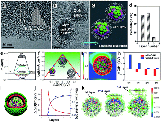
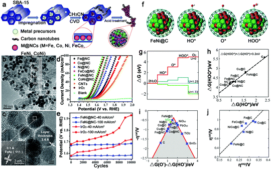
The alloy phase can not only copy the individual advanced properties, but also usually exhibit amazing catalytic performance because of possible synergetic effects. Thus, alloy–N–C catalysts for water splitting have attracted major interest. And the Bao group has made great contributions to this area. To synthesize ultrathin carbon shells to promote electron transfer from metal cores to the carbon surface, thereby optimizing the electronic structure of the carbon surface, they fabricated a hierarchical architecture in which the uniform CoNi nanoalloy (4–7 nm) was encapsulated in ultrathin graphene shells (only 1–3 layers) for HER in 0.1 M H2SO4 (Fig. 15a–d).127 This catalyst exhibited an overpotential of 140 mV at 10 mA cm−2 with a Tafel slope of 105 mV dec−1. The DFT calculations showed a more moderate ΔGH* for the CoNi@C than for the others, and the nitrogen dopants and metal cores could synergistically optimize the ΔGH* (Fig. 15e–h). Moreover, the effect of the graphene layer on the HER was also studied by using a model in which a CoNi cluster was encapsulated by one to three graphene layers, as shown in Fig. 15i–k, which showed that the thinner the graphene shells, the higher the HER performance. Based on these results, decreasing the carbon layer thickness strongly promotes electron penetration from the CoNi nanoalloy to the carbon surface, which contributes to the modulation of the electron density and the electronic potential distribution at the surface accompanied by the N dopants, and then results in superior HER activity.To further decrease the carbon shell thickness, recently the group also prepared single layer graphene encapsulating metal nanoparticles for OER, including Fe, Co, Ni and their alloys (Fig. 16a–c).128 Here, the encapsulated FeNi alloy exhibited the best OER activity in alkaline solutions with 10 mA cm−2 obtained at an overpotential of only 280 mV, and a high stability after 10![[thin space (1/6-em)]](https://www.rsc.org/images/entities/char_2009.gif) 000 CV cycles, which was superior to that of other FeNi–N–C materials (Fig. 16d and e).69,129 They also fabricated a model and calculated the free energies of various intermediates for OER (Fig. 16f and g). The ΔG(HOO*) and ΔG(HO*) showed a linear relationship (Fig. 16h); thus, the overpotential could be determined from ΔG(O*) − ΔG(HO*). As shown in Fig. 16i, FeNi@C was closest to the volcano peak, indicating the best catalytic performance. And the same trend in calculated overpotential and experimental results suggested that this theoretical model could predict the efficiency of M@C in OER (Fig. 16j).
000 CV cycles, which was superior to that of other FeNi–N–C materials (Fig. 16d and e).69,129 They also fabricated a model and calculated the free energies of various intermediates for OER (Fig. 16f and g). The ΔG(HOO*) and ΔG(HO*) showed a linear relationship (Fig. 16h); thus, the overpotential could be determined from ΔG(O*) − ΔG(HO*). As shown in Fig. 16i, FeNi@C was closest to the volcano peak, indicating the best catalytic performance. And the same trend in calculated overpotential and experimental results suggested that this theoretical model could predict the efficiency of M@C in OER (Fig. 16j).
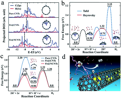
In addition, Bao et al. also embedded FeCo alloy into N–CNTs (FeCo@NCNTs), and the obtained catalyst exhibited stable and high HER activity with an onset potential of 70 mV in acid.113 The calculated ΔGH* demonstrated that N and metal embedding significantly optimized the hydrogen adsorption on CNTs synergistically, and the introduction of Co was more efficient than the introduction of Fe which was consistent with the experimental results. As shown in Fig. 17a, strong H–C chemical bonding can be formed on the carbon surface of Fe@CNTs based on the band center of the occupied states of the C–H bond on Fe@CNTs locating in a low energy regime. Moreover, the reaction mechanism was also studied by DFT calculations (Fig. 17b and c), indicating that the Volmer–Heyrovsky mechanism was the predominant route in this catalytic system. In addition, to optimize the N content, FeCo alloy nanoparticles encapsulated in highly N-doped (8.2 atom%) graphene layers were synthesized,130 which showed similar activity to the above FeCo@NCNTs. The DFT calculations showed that the N dopants could provide adsorption sites for H*, and the appropriate increase in N and the unique structure would decrease the ΔGH* for HER, thereby promoting the catalytic activity. Recently, a comprehensive understanding of FeCo coated with N–C was reported, based on theoretical calculations and experimental validations.131 The effects of N-doping level and active N sites, the thickness of the carbon layers, and the binary alloying elements on catalytic activity were thoroughly analyzed, which should all be considered in synthesizing high-performance catalysts. FeCo@NC core–shell nanoparticles also displayed high OER activity with 10 mA cm−2 achieved at a potential of only 1.49 V in alkaline medium.132
Alloy–N–C catalysts based on other alloy component have also been fabricated for water splitting. For instance, Zheng et al. synthesized NiMo encapsulated in N–graphite nanotubes (NiMo–NGTs) for HER in acid,133 which exhibited high performance with an overpotential of only 65 mV at 10 mA cm−2 due to the synergetic effect of the Ni–Mo alloy and Mo2C nanoparticles, as well as the NGT. However, the interaction between the metallic Ni phases and the Mo compound was not clear. Recently, Chen et al. also designed ternary alloys encapsulated in graphene for overall water splitting.134 According to the DFT calculation, as for HER, the alloy with the most transferred electrons will exhibit the best HER performance. Whereas for OER, a proper number of transferred electrons which might result in an optimal value of ΔG(O*) − ΔG(HO*) in the volcano plot could enhance OER activity, which was similar to the previous report.128 Thus, the change in alloy composition and proportion can further tune the surface electronic structures of carbon-encapsulated alloys by altering the number of transferred electrons to optimize the catalytic activity. In addition, the group also prepared an alloy of noble metal–N–C (PdCo@CN) catalyst for HER,135 which showed outstanding performance with an overpotential of 80 mV at 10 mA cm−2, a Tafel slope of 31 mV dec−1, and excellent stability of 10![[thin space (1/6-em)]](https://www.rsc.org/images/entities/char_2009.gif) 000 cycles.
000 cycles.
5. Summary and outlook
In conclusion, this review has profiled several major kinds of M–N–C based materials for applications to electrochemical water splitting. A detailed comparison of their electrochemical performances was listed in Tables 1 and 2. We also briefly discussed the M–N–C structures and synthesis methods. The listed catalyst synthesis methods, including the precursors and treatment conditions, are summarized in Table 3. Based on the above experimental and theoretical results, we concluded that the synergistic effect of metal and N, as well as the carbon substrate contributed to the catalytic performance. Further study also demonstrated that the different metals, N contents and the carbon layer thickness all had significance effects on the activity. In addition, the experimental solar cell devices using these catalysts made a further step towards environmentally friendly hydrogen production.| Catalysts | Electrolyte | Loading (mg cm−2) | Overpotential (mV) | Tafel slope (mA cm−2) | Exchange current density (mA cm−2) | Stability | Ref. |
|---|---|---|---|---|---|---|---|
| Co@NG | 0.5 M H2SO4 | 1.08 | η 10 = 172 | 100 | — | 10![[thin space (1/6-em)]](https://www.rsc.org/images/entities/char_2009.gif) 000 CV cycles 000 CV cycles |
74 |
| 1 M KOH | η 10 = 200 | 112 | |||||
| Co–NRCNTs | 0.5 M H2SO4 | 0.28 | η 10 = 260 | 69 | — | 8.5 h | 75 |
| phosphate buffer | η 10 = 540 | — | |||||
| 1 M KOH | η 10 = 370 | — | |||||
| Co@BCN | 0.5 M H2SO4 | — | η 10 = 96 | 63.7 | 0.103 | 10 h | 73 |
| 1 M KOH | η 10 = 183 | 73.2 | — | ||||
| Co–NCNT/CC | 0.5 M H2SO4 | 3.4 | η 10 = 78 | 74 | 0.38 | 40 h | 78 |
| phosphate buffer | η 10 = 170 | 97 | — | ||||
| 1 M KOH | η 10 = 180 | 193 | — | ||||
| Co–N–GA | 0.5 M H2SO4 | 0.28 | η 10 = 46 | 33 | — | 5000 CV cycles | 79 |
| phosphate buffer | η 10 = 299 | 159 | |||||
| 1.0 M KOH | η 10 = 232 | 102 | |||||
| Co@Co–N–C | 0.1 M KOH | — | η 10 = 314 | 59 | — | 2000 CV cycles | 76 |
| Co@NC/NG | 0.5 M H2SO4 | 0.285 | η 13.6 = 200 | 79.3 | — | 1000 CV cycles | 77 |
| Co@NC/Ti | 0.5 M H2SO4 | 11.2 | η 10 = 106 | 78.2 | — | 1000 CV cycles | 80 |
| Co–N–C | 0.5 M H2SO4 | 0.765 | η 10 = 235 | 90 | — | 1000 CV cycles | 81 |
| Co–NC/NRGO | 0.5 M H2SO4 | 0.35 | η 10 = 229 | 126 | — | 5000 CV cycles | 91 |
| Co–C–N/CFP | 0.5 M H2SO4 | — | η 10 = 138 | 55 | — | 40 h | 82 |
| phosphate buffer | η 10 = 273 | 107 | |||||
| 1.0 M KOH | η 10 = 178 | 102 | |||||
| CoNx/C | 0.5 M H2SO4 | 2.0 | η 10 = 133 | 57 | 0.07 | 5000 CV cycles | 83 |
| phosphate buffer | η 10 = 247 | — | — | ||||
| 1.0 M KOH | η 10 = 170 | 75 | — | ||||
| CoNC/GD | 0.5 M H2SO4 | 0.256 | η 10 = 340 | 138 | — | 38![[thin space (1/6-em)]](https://www.rsc.org/images/entities/char_2009.gif) 000 CV cycles 000 CV cycles |
106 |
| phosphate buffer | η 10 = 368 | 207 | 9000 CV cycles | ||||
| 1.0 M KOH | η 10 = 284 | 115 | 36![[thin space (1/6-em)]](https://www.rsc.org/images/entities/char_2009.gif) 000 CV cycles 000 CV cycles |
||||
| Co@N–C | 1 M HClO4 | — | η 10 = 200 | 100 | — | 10![[thin space (1/6-em)]](https://www.rsc.org/images/entities/char_2009.gif) 000 CV cycles 000 CV cycles |
94 |
| 1 M KOH | η 10 = 210 | 108 | |||||
| Co–NC/CNT | 1 M KOH | 0.306 | η 10 = 203 | 125 | — | 1000 CV cycles | 95 |
| Co@NCNT | 0.5 M H2SO4 | — | η 10 = 210 | 93 | — | 20![[thin space (1/6-em)]](https://www.rsc.org/images/entities/char_2009.gif) 000 s 000 s |
96 |
| CoOx@CN | 1 M KOH | 0.12 | η 10 = 232 | 115 | — | — | 97 |
| Co–P/NC | 1 M KOH | 1 | η 10 = 154 | 51 | — | 1000 CV cycles | 107 |
| Co–P/NC/CC | 1 M KOH | — | η 10 = 171 | 52 | — | — | 108 |
| Co–NG | 0.5 M H2SO4 | 0.285 | η 10 = 147 | 82 | — | 10 h | 98 |
| Ni–C–N | 0.5 M H2SO4 | 0.2 | η 10 = 60.9 | 32 | 0.0136 | 70 h | 109 |
| phosphate buffer | η 10 = 92.1 | 38 | — | ||||
| 1 M KOH | η 10 = 30.8 | 40 | — | ||||
| A–Ni–C | 0.5 M H2SO4 | 0.283 | η 10 = 34 | 41 | 1.2 | 25 h | 111 |
| Fe3C/Mo2C@NPGC | 0.5 M H2SO4 | — | η 10 = 98 | 45.2 | 0.104 | 10 h | 118 |
| Au@NC | 0.5 M H2SO4 | 0.357 | η 10 = 130 | 76.8 | 0.186 | 20 h | 121 |
| Pt/NGNs | 0.5 M H2SO4 | 0.076 | η 16 = 50 | 29 | — | 1000 CV cycles | 126 |
| CoNi@NC | 0.1 M H2SO4 | 0.32 | η 10 = 224 | 104 | — | 24 h | 127 |
| FeCo@NCNTs | 0.1 M H2SO4 | 0.32 | η onset = 70 | 74 | — | 10![[thin space (1/6-em)]](https://www.rsc.org/images/entities/char_2009.gif) 000 CV cycles 000 CV cycles |
113 |
| FeCo@N–GR | 0.5 M H2SO4 | 0.285 | η 10 = 262 | 74 | — | 10![[thin space (1/6-em)]](https://www.rsc.org/images/entities/char_2009.gif) 000 CV cycles 000 CV cycles |
130 |
| FeCo@NC | 0.5 M H2SO4 | — | η 10 = 240 | 92 | — | 10![[thin space (1/6-em)]](https://www.rsc.org/images/entities/char_2009.gif) 000 CV cycles 000 CV cycles |
131 |
| NiMo–NGTs | 0.5 M H2SO4 | 2 | η 10 = 65 | 67 | 0.84 | 10![[thin space (1/6-em)]](https://www.rsc.org/images/entities/char_2009.gif) 000 CV cycles 000 CV cycles |
133 |
| PdCo@CN | 0.5 M H2SO4 | 0.285 | η 10 = 80 | 31 | — | 10![[thin space (1/6-em)]](https://www.rsc.org/images/entities/char_2009.gif) 000 CV cycles 000 CV cycles |
135 |
| Catalysts | Electrolyte | Loading (mg cm−2) | Overpotential (mV) | Tafel slope (mA cm−2) | Stability | Ref. |
|---|---|---|---|---|---|---|
| Co–N–CNTs | Phosphate buffer | 1.0 | η 10 = 300 | 50 | 6 h | 84 |
| 1.0 M KOH | η 50 = 300 | 40 | ||||
| Co–N–GCI | 0.1 M KOH | 0.5 | η 10 = 426 | — | 200 CV cycles | 85 |
| Co@Co3O4/NC | 0.1 M KOH | 0.21 | η 10 = 410 | 53 | 45 h | 86 |
| Co–N–C | 0.1 M KOH | 0.4 | η 10 = 390 | 110 | 10 h | 88 |
| Co/N–C | 0.1 M KOH | 0.25 | η 10 = 371 | 61.4 | 500 CV cycles | 89 |
| Co–NC/NRGO | 0.1 M KOH | 0.35 | η 10 = 430 | 292 | 6000 s | 91 |
| Co@N–C | 1.0 M KOH | — | η 10 = 400 | — | 550 min | 94 |
| Co–NC/CNT | 1.0 M KOH | 0.306 | η 10 = 354 | 78 | 1000 CV cycles | 95 |
| Co@NCNT | 1.0 M KOH | — | η 10 = 429 | 116 | — | 96 |
| CoOx@CN | 1.0 M KOH | 1 | η 10 = 260 | — | — | 97 |
| Co–P/NC | 1.0 M KOH | 1 | η 10 = 319 | 52 | 1000 CV cycles | 107 |
| Co–P/NC/CC | 1.0 M KOH | — | η 10 = 330 | 61 | 50 h | 108 |
| Ni@NC | 0.1 M KOH | 0.4 | η 10 = 390 | 40 | 10 h | 112 |
| Fe–N–C | 0.1 M KOH | 0.6 | η 10 = 370 | 82 | — | 115 |
| Fe3C@NCNT/NPC | 1.0 M KOH | — | η 10 = 340 | 62 | 1000 CV cycles | 116 |
| FeNC | 0.1 M KOH | 0.15 | η 10 = 410 | 137 | 5000 s | 117 |
| FeNi@NC | 1.0 M NaOH | 0.32 | η 10 = 280 | 70 | 10![[thin space (1/6-em)]](https://www.rsc.org/images/entities/char_2009.gif) 000 CV cycles 000 CV cycles |
128 |
| NiFe@NCx | 0.1 M KOH | 0.4 | η 10 = 230 | 60.6 | 1000 CV cycles | 129 |
| FeCo@NC | 1.0 M KOH | 0.8 | η 10 = 260 | 62 | 6 h | 131 |
| FeCoNi/N–GR | 1.0 M KOH | 1 | η 10 = 288 | 60 | 1000 CV cycles | 134 |
| Catalysts[ref.] | Precursors | Synthesis conditions |
|---|---|---|
| Co@BCN73 | ZIF-67 and H3BO3 | Calcination at 450 °C in Ar atmosphere, then increased to 750 °C |
| Co@NG74 | Co-containing prussian blue colloids | Annealed in Ar at 600 °C for 1 h and then acid treatment |
| Co–NRCNTs75 | Dicyandiamide and CoCl2·6H2O | Thermal treatment at 500 and 700 °C in N2 atmosphere, and then acid treatment |
| Co@Co–N–C76 | Co(OH)(CO3)0.5·0.11H2O@polymerized glucose and melamine | Calcination in Ar atmosphere at 800 °C for 2 h |
| Co@NC/NG77 | Co(Ac)2·4H2O, cyanamide, graphene oxide | Thermal treatment at 500 and 700 °C in N2 atmosphere for 2 h, followed by acid treatment |
| Co–NCNT/CC78 | Dicyanodiamine and Co3O4/CC | Calcination at 400 and 700 °C for 2 h, respectively, and then acid treatment |
| Co–N–GA79 | MOFs@graphene | Pyrolysis at 900 °C for 2 h in Ar atmosphere |
| Co@NC/Ti80 | Co3O4/Ti and dicyanodiamine | Calcination at 700 °C in Ar atmosphere |
| Co–N–C81 | Co(NO3)2·6H2O, aniline and carbon black | Treatment at 900 °C in Ar atmosphere for 1 h, and then acid treatment |
| Co–C–N/CFP82 | Co(NO3)2·6H2O and polyaniline | Carbonized at 750 °C in N2 atmosphere, and then acid treatment |
| CoNx/C83 | Co/o-phenylenediamine | Pyrolysis at 900 °C under N2 atmosphere for 2 h, alkali treatment, second heat treatment, acid treatment, third heat treatment |
| Co–N–CNTs84 | Co-phthalocyanine and carbon nanotube | Heated at 900 °C for 2 h in Ar, and then acid treatment |
| Co–N–GCI85 | Co(Ac)2·4H2O, melamine and carbon nanospheres | Thermal treatment at 750 °C for 30 min under Ar flow |
| Co@Co3O4/NC86 | ZIF-67 | Pyrolysis in H2 atmosphere and subsequent controlled oxidative calcination |
| Co–N/C87 | CoCl2·6H2O, hdatrz and carbon black | Thermal-treated at 600 °C for 2 h under N2 atmosphere |
| Co–N–C88 | Co(Ac)2·4H2O and g-C3N4 | Calcination at 500 °C 2 h and 700 °C for 4 h under N2 atmosphere, respectively, and then acid treatment, 800 °C again in N2 atmosphere for 2 h |
| Co/N–C89 | Co(Ac)2·4H2O and dopamine hydrochloride | Thermal-treated at 800 °C for 2 h under Ar atmosphere |
| Co/N–C90 | Dikaryon phthalocyanine Co sulfonate | Pyrolysis at 900 °C and constant pressure of 1.5 Torr for 2 h under N2 atmosphere |
| Co–NC/NRGO91 | ZIF-67 and graphene oxide | Thermally treated under flowing Ar at 900 °C and then acid treatment |
| Co/CoO@Co–N–C92 | Co(NO3)2, N-doped carbon nanodots and pyrrole | Thermal-treated at 800 °C for 2 h under N2 atmosphere |
| Co@N–C94 | Co(Ac)2·4H2O and imidazole | Pyrolysis at 900 °C in Ar atmosphere for 2 h, acid treatment, 900 °C again in Ar atmosphere for 1 h |
| Co–NC/CNT95 | ZIF-67 and CNTs | Pyrolysis at 800 °C under N2 flow for 2 h and acid treatment |
| Co@NCNT96 | ZIF-67 and dicyandiamide | Calcination at 500 °C 30 min and 750 °C for 2 h under flowing Ar, and then acid treatment |
| CoOx@CN97 | CoNO3·6H2O, melamine and D(+)-glucosamine hydrochloride | Calcination at 600 °C 1 h and 800 °C for 1 h in N2 atmosphere, respectively |
| Co–NG98 | CoCl2·6H2O and graphene oxide | Calcination at 750 °C for 1 h under NH3 atmosphere |
| CoNC/GD106 | Co(oAc)2, DCD and GD | Calcination at 500 °C 2 h and 700 °C for 2 h in Ar atmosphere, and then acid treatment |
| Co–C3N4/CNT122 | CoCl2·6H2O, CNT and DCDA | Thermal-treated at 600 °C under N2 atmosphere |
| Co–P/NC107 | ZIF-67 and NaH2PO2·H2O | Carbonization of ZIF-67 followed by phosphidation |
| Co–P/NC/CC108 | ZIF-67/CC and NaH2PO2·H2O | Carbonization of ZIF-67/CC followed by phosphidation |
| Ni–C–N109 | Ni–polyoxometalate MOF | Carbonization Ni–MOF in NH3 atmosphere at 380 °C for 3 h, acid treatment, followed by exfoliation |
| A–Ni–C111 | Ni–MOF | Carbonization at 700 °C in N2 atmosphere, and then treatment |
| Ni@NC112 | Ni(Ac)2 and phenanthroline | Carbonization at 800 °C under N2 flow for 1.5 h |
| Fe–N–C114 | Fe phthalocyanine | Carbonized at 900 °C for 3 h under Ar atmosphere |
| Fe–N–C115 | CNTs with 2,2-bipyridine and FeCl3 | Pyrolysis at 900 °C under N2 atmosphere and acid leaching |
| Fe3C@NCNT/NPC116 | MIL-88B and melamine | Calcination at 550 °C 3 h and 800 °C for 2 h in N2 atmosphere, respectively, and then acid treatment |
| FeNC117 | FeCl3, o-phthalic anhydride, and melamine | Calcination at 550 °C 3 h and 800 °C for 2 h in N2 atmosphere, and then acid treatment |
| Fe3C/Mo2C@NPGC118 | PMo12@MIL-100 (Fe) and melamine | Pyrolysis at 900 °C under N2 atmosphere |
| CoNi@NC127 | Co(NO3)2, Ni(NO3)2, and Na4EDTA | Annealed at a temperature range of 425 to 600 °C for 3 h in Ar, and then acid treatment |
| NiFe@NCx129 | NiFe-MILs and melamine | Calcination at 600 °C for 1 h and 800 °C for 1 h in N2 atmosphere, and then acid treatment |
| FeCo@N–GR130 | Fe3[Co(CN)6]2 | Annealing of MOF nanoparticles at 600 °C in N2 |
| FeCo@NC131 | Fe(NO3)3·9H2O, Co(NO3)2·6H2O, glucose and ammonium sulfate | Pyrolysis at 1000 °C, acid treatment and treated again at 1000 °C for 1 h under Ar flow |
| FeCo@NC132 | Co–Fe prussian blue analogue | Thermal decomposition in Ar atmosphere |
| NiMo–NGTs133 | Ni(Ac)2·4H2O, dicyandiamide (NH4)6Mo7O24·4H2O | Calcination at 600 °C 2 h in a 5![[thin space (1/6-em)]](https://www.rsc.org/images/entities/char_2009.gif) : :![[thin space (1/6-em)]](https://www.rsc.org/images/entities/char_2009.gif) 2 Ar/H2 (v/v) atmosphere 2 Ar/H2 (v/v) atmosphere |
| FeCoNi/N–GR134 | Fe3[Co(CN)6]2 and Ni3[Co(CN)6]2 | Annealed under N2 atmosphere at 600 °C for 4 h |
| PdCo@CN135 | Pd-Doped MOFs | Annealed under N2 atmosphere at 500 °C for 4 h |
Despite these meaningful conclusions, several challenges still remain. (i) The limit of synthesis methods leads to many adverse effects. For instance, during the general pyrolysis process, many factors, such as temperature and gas flow rate, give products poor reproducibility. Thus, it is hard to move on to large-scale production and the precise composition control of catalyst materials. Furthermore, the controllable synthesis of catalysts with a large effective surface area and a high density of catalytic active sites are seldom achieved at the same time. (ii) The atomic structure and catalytic mechanism of the M–N–C catalysts are still hard to illustrate clearly, due to the complex nature of these catalysts. So the nature of the real active sites in M–N–C composites for water electrolysis remains a topic of controversy, which goes against effective catalyst design and causes great puzzlement in the further understanding of these reactions.
The rapid development of M–N–C catalysts for water splitting always results in insufficient understanding. Nowadays, many researchers focus on preparing M–N–C catalysts with different components and then characterize their electrochemical performance. More attention should be paid to the mechanistic and fundamental insights of M–N–C catalysts in the water electrolysis process. Some future directions are now discussed, which may be expanded to other systems. (i) The best catalytic performance is still far from the expectations for practical applications, which should lead to further improvement. The catalytic performance can be further enhanced by optimizing the M–N binding properties and catalyst structures with a large effective surface area and a high density of catalytic active sites, as well as the relationships between metal, carbon layers and N-doping level, and even heteroatom doping, etc. In addition, the metal and/or its oxide, carbide, nitride and phosphide, and even other coordinated atoms, such as molecular M–Sx and M–Px, should be considered. Moreover, other carbon matrixes, such as the above-mentioned graphdiyne and g-C3N4 should be also designed and studied. (ii) Theoretical calculation is a powerful technology to illustrate many profound questions, such as the effect of crystal structure, heteroatom doping and electronic state. These theories, combined with the above factors, can help us gain deep insight into the mechanism, and then guide us in designing and optimizing M–N–C catalysts with high performance. (iii) Considering practical applications, fabricating integrated bifunctional electrodes with special structures in the same electrolyte for water electrolysis should be also considered. Integrated electrodes can avoid not only time- and cost-consuming processes, but also the disadvantages of using polymer binders, such as increasing series resistance, blocking active sites and inhibiting diffusion. And working in the same electrolyte allows a simpler design of electrolyzer systems. Also, a combination of these catalysts with solar cell devices should be tried, and only a few workers focus on this. (iv) A lack of understanding of the molecular-level interfacial structural transformation and reaction mechanisms will always hinder the further development of this thriving field. Once acquired, a new comprehensive understanding in this area by advanced in situ characterization techniques, will be another big step towards electrochemical water splitting.
Acknowledgements
This work was supported by National Natural Science Foundation of China (51522101, 51471075, 5163100, and 51401084); and Specialized Research Fund for the Doctoral Program of Higher Education of China (20110061120040).Notes and references
- Y. Yan, B. Y. Xia, Z. C. Xu and X. Wang, ACS Catal., 2014, 4, 1693–1705 CrossRef CAS.
- T. R. Cook, D. K. Dogutan, S. Y. Reece, Y. Surendranath, T. S. Teets and D. G. Nocera, Chem. Rev., 2010, 110, 6474–6502 CrossRef CAS PubMed.
- M. G. Walter, E. L. Warren, J. R. McKone, S. W. Boettcher, Q. Mi, E. A. Santori and N. S. Lewis, Chem. Rev., 2010, 110, 6446–6473 CrossRef CAS PubMed.
- Z. W. Seh, J. Kibsgaard, C. F. Dickens, I. Chorkendorff, J. K. Norskov and T. F. Jaramillo, Science, 2017, 355 Search PubMed.
- L. M. Amoo and R. L. Fagbenle, Int. J. Hydrogen Energy, 2014, 39, 12409–12433 CrossRef CAS.
- J. A. Turner, Science, 2004, 305, 972–974 CrossRef CAS PubMed.
- X. Zou and Y. Zhang, Chem. Soc. Rev., 2015, 44, 5148–5180 RSC.
- J. Wang, W. Cui, Q. Liu, Z. Xing, A. M. Asiri and X. Sun, Adv. Mater., 2016, 28, 215–230 CrossRef CAS PubMed.
- A. Kudo and Y. Miseki, Chem. Soc. Rev., 2009, 38, 253–278 RSC.
- V. S. Thoi, Y. Sun, J. R. Long and C. J. Chang, Chem. Soc. Rev., 2013, 42, 2388–2400 RSC.
- T. Abbasi and S. A. Abbasi, Renewable Sustainable Energy Rev., 2011, 15, 3034–3040 CrossRef.
- M. Wang, Z. Wang, X. Gong and Z. Guo, Renewable Sustainable Energy Rev., 2014, 29, 573–588 CrossRef CAS.
- J. A. Turner, Science, 1999, 285, 687–689 CrossRef CAS PubMed.
- J. Wang, H.-X. Zhong, Z.-L. Wang, F.-L. Meng and X.-B. Zhang, ACS Nano, 2016, 10, 2342–2348 CrossRef CAS PubMed.
- D. Voiry, H. Yamaguchi, J. Li, R. Silva, D. C. B. Alves, T. Fujita, M. Chen, T. Asefa, V. B. Shenoy, G. Eda and M. Chhowalla, Nat. Mater., 2013, 12, 850–855 CrossRef CAS PubMed.
- T. Y. Ma, J. Ran, S. Dai, M. Jaroniec and S. Z. Qiao, Angew. Chem., Int. Ed., 2015, 54, 4646–4650 CrossRef CAS PubMed.
- Y. Zheng, Y. Jiao, M. Jaroniec and S. Z. Qiao, Angew. Chem., Int. Ed., 2015, 54, 52–65 CrossRef CAS PubMed.
- P. Jiang, Q. Liu, Y. Liang, J. Tian, A. M. Asiri and X. Sun, Angew. Chem., Int. Ed., 2014, 53, 12855–12859 CrossRef CAS PubMed.
- J. Q. Tian, Q. Liu, A. M. Asiri and X. P. Sun, J. Am. Chem. Soc., 2014, 136, 7587–7590 CrossRef CAS PubMed.
- J.-S. Li, Y. Wang, C.-H. Liu, S.-L. Li, Y.-G. Wang, L.-Z. Dong, Z.-H. Dai, Y.-F. Li and Y.-Q. Lan, Nat. Commun., 2016, 7, 11204 CrossRef CAS PubMed.
- W. Liu, E. Hu, H. Jiang, Y. Xiang, Z. Weng, M. Li, Q. Fan, X. Yu, E. I. Altman and H. Wang, Nat. Commun., 2016, 7, 10771 CrossRef CAS PubMed.
- Y. Jiao, Y. Zheng, K. Davey and S.-Z. Qiao, Nat. Energy, 2016, 1, 16130 CrossRef CAS.
- H. Zhong, J. Wang, F. Meng and X. Zhang, Angew. Chem., Int. Ed., 2016, 55, 9937–9941 CrossRef CAS PubMed.
- M. Gong, Y. Li, H. Wang, Y. Liang, J. Z. Wu, J. Zhou, J. Wang, T. Regier, F. Wei and H. Dai, J. Am. Chem. Soc., 2013, 135, 8452–8455 CrossRef CAS PubMed.
- T. Y. Ma, S. Dai, M. Jaroniec and S. Z. Qiao, J. Am. Chem. Soc., 2014, 136, 13925–13931 CrossRef CAS PubMed.
- X. Lu and C. Zhao, Nat. Commun., 2015, 6, 6616 CrossRef CAS PubMed.
- J. Liang, R. F. Zhou, X. M. Chen, Y. H. Tang and S. Z. Qiao, Adv. Mater., 2014, 26, 6074–6079 CrossRef CAS PubMed.
- L. Dai, Y. Xue, L. Qu, H.-J. Choi and J.-B. Baek, Chem. Rev., 2015, 115, 4823–4892 CrossRef CAS PubMed.
- Y. Nie, L. Li and Z. Wei, Chem. Soc. Rev., 2015, 44, 2168–2201 RSC.
- T. Zhou, Y. Du, S. Yin, X. Tian, H. Yang, X. Wang, B. Liu, H. Zheng, S. Qiao and R. Xu, Energy Environ. Sci., 2016, 9, 2563–2570 CAS.
- G. Wu, K. L. More, C. M. Johnston and P. Zelenay, Science, 2011, 332, 443–447 CrossRef CAS PubMed.
- Z. Dong, H. Ren, C. M. Hessel, J. Wang, R. Yu, Q. Jin, M. Yang, Z. Hu, Y. Chen, Z. Tang, H. Zhao and D. Wang, Adv. Mater., 2014, 26, 905–909 CrossRef CAS PubMed.
- J. Wang, H. Tang, H. Ren, R. Yu, J. Qi, D. Mao, H. Zhao and D. Wang, Adv. Sci., 2014, 1, 1400011 CrossRef PubMed.
- J. Wang, N. Yang, H. Tang, Z. Dong, Q. Jin, M. Yang, D. Kisailus, H. Zhao, Z. Tang and D. Wang, Angew. Chem., Int. Ed., 2013, 52, 6417–6420 CrossRef CAS PubMed.
- J. Qi, X. Lai, J. Wang, H. Tang, H. Ren, Y. Yang, Q. Jin, L. Zhang, R. Yu, G. Ma, Z. Su, H. Zhao and D. Wang, Chem. Soc. Rev., 2015, 44, 6749–6773 RSC.
- S. Xu, C. M. Hessel, H. Ren, R. Yu, Q. Jin, M. Yang, H. Zhao and D. Wang, Energy Environ. Sci., 2014, 7, 632–637 CAS.
- J. Zhang, H. Ren, J. Wang, J. Qi, R. Yu, D. Wang and Y. Liu, J. Mater. Chem. A, 2016, 4, 17673–17677 CAS.
- J. Wang, H. Tang, H. Wang, R. Yu and D. Wang, Mater. Chem. Front., 2017, 1, 414–430 RSC.
- H. Ren, R. Yu, J. Wang, Q. Jin, M. Yang, D. Mao, D. Kisailus, H. Zhao and D. Wang, Nano Lett., 2014, 14, 6679–6684 CrossRef CAS PubMed.
- J. Qi, K. Zhao, G. Li, Y. Gao, H. Zhao, R. Yu and Z. Tang, Nanoscale, 2014, 6, 4072–4077 RSC.
- J. Wang, H. Tang, L. Zhang, H. Ren, R. Yu, Q. Jin, J. Qi, D. Mao, M. Yang, Y. Wang, P. Liu, Y. Zhang, Y. Wen, L. Gu, G. Ma, Z. Su, Z. Tang, H. Zhao and D. Wang, Nat. Energy, 2016, 1, 16050 CrossRef CAS.
- C. G. Morales-Guio, L. A. Stern and X. L. Hu, Chem. Soc. Rev., 2014, 43, 6555–6569 RSC.
- Y. Shi and B. Zhang, Chem. Soc. Rev., 2016, 45, 1529–1541 RSC.
- M. Zeng and Y. Li, J. Mater. Chem. A, 2015, 3, 14942–14962 CAS.
- R. Jasinski, Nature, 1964, 201, 1212 CrossRef CAS.
- M. Zhou, C. Z. Yang and K. Y. Chan, Adv. Energy Mater., 2014, 4, 1400840 CrossRef.
- M. Xiao, J. Zhu, L. Feng, C. Liu and W. Xing, Adv. Mater., 2015, 27, 2521–2527 CrossRef CAS PubMed.
- Y. Hu, J. O. Jensen, W. Zhang, L. N. Cleemann, W. Xing, N. J. Bjerrum and Q. Li, Angew. Chem., Int. Ed., 2014, 53, 3675–3679 CrossRef CAS PubMed.
- U. Tylus, Q. Jia, K. Strickland, N. Ramaswamy, A. Serov, P. Atanassov and S. Mukerjee, J. Phys. Chem. C, 2014, 118, 8999–9008 CAS.
- K. Shen, X. Chen, J. Chen and Y. Li, ACS Catal., 2016, 6, 5887–5903 CrossRef CAS.
- S. Ganesan, N. Leonard and S. C. Barton, Phys. Chem. Chem. Phys., 2014, 16, 4576–4585 RSC.
- M. Lefevre, J. P. Dodelet and P. Bertrand, J. Phys. Chem. B, 2000, 104, 11238–11247 CrossRef CAS.
- U. I. Kramm, J. Herranz, N. Larouche, T. M. Arruda, M. Lefevre, F. Jaouen, P. Bogdanoff, S. Fiechter, I. Abs-Wurmbach, S. Mukerjee and J. P. Dodelet, Phys. Chem. Chem. Phys., 2012, 14, 11673–11688 RSC.
- A. Zitolo, V. Goellner, V. Armel, M. T. Sougrati, T. Mineva, L. Stievano, E. Fonda and F. Jaouen, Nat. Mater., 2015, 14, 937–942 CrossRef CAS PubMed.
- W. Liu, L. Zhang, W. Yan, X. Liu, X. Yang, S. Miao, W. Wang, A. Wang and T. Zhang, Chem. Sci., 2016, 7, 5758–5764 RSC.
- A. Mahmood, W. Guo, H. Tabassum and R. Zou, Adv. Energy Mater., 2016, 6, 1600423 CrossRef.
- Z.-F. Ma, X.-Y. Xie, X.-X. Ma, D.-Y. Zhang, Q. Ren, N. Heß-Mohr and V. M. Schmidt, Electrochem. Commun., 2006, 8, 389–394 CrossRef CAS.
- H. Liu, C. Song, Y. Tang, J. Zhang and J. Zhang, Electrochim. Acta, 2007, 52, 4532–4538 CrossRef CAS.
- F. Jaouen, F. Charreteur and J. P. Dodelet, J. Electrochem. Soc., 2006, 153, A689 CrossRef CAS.
- M. Lefevre, E. Proietti, F. Jaouen and J.-P. Dodelet, Science, 2009, 324, 71–74 CrossRef CAS PubMed.
- D. Deng, L. Yu, X. Chen, G. Wang, L. Jin, X. Pan, J. Deng, G. Sun and X. Bao, Angew. Chem., Int. Ed., 2013, 52, 371–375 CrossRef CAS PubMed.
- H. Xiao, Z.-G. Shao, G. Zhang, Y. Gao, W. Lu and B. Yi, Carbon, 2013, 57, 443–451 CrossRef CAS.
- J.-S. Lee, G. S. Park, S. T. Kim, M. Liu and J. Cho, Angew. Chem., Int. Ed., 2013, 52, 1026–1030 CrossRef CAS PubMed.
- K. Ai, Y. Liu, C. Ruan, L. Lu and G. M. Lu, Adv. Mater., 2013, 25, 998–1003 CrossRef CAS PubMed.
- G. Wu, C. M. Johnston, N. H. Mack, K. Artyushkova, M. Ferrandon, M. Nelson, J. S. Lezama-Pacheco, S. D. Conradson, K. L. More, D. J. Myers and P. Zelenay, J. Mater. Chem., 2011, 21, 11392 RSC.
- A. Kong, X. Zhu, Z. Han, Y. Yu, Y. Zhang, B. Dong and Y. Shan, ACS Catal., 2014, 4, 1793–1800 CrossRef CAS.
- F. L. Meng, Z. L. Wang, H. X. Zhong, J. Wang, J. M. Yan and X. B. Zhang, Adv. Mater., 2016, 28, 7948–7955 CrossRef CAS PubMed.
- Y. V. Kaneti, J. Tang, R. R. Salunkhe, X. Jiang, A. Yu, K. C. Wu and Y. Yamauchi, Adv. Mater., 2017, 29, 1604898 CrossRef PubMed.
- Z. Tao, T. Wang, X. Wang, J. Zheng and X. Li, ACS Appl. Mater. Interfaces, 2016, 8, 35390–35397 CAS.
- K. Shen, L. Chen, J. Long, W. Zhong and Y. Li, ACS Catal., 2015, 5, 5264–5271 CrossRef CAS.
- E. Proietti, F. Jaouen, M. Lefevre, N. Larouche, J. Tian, J. Herranz and J. P. Dodelet, Nat. Commun., 2011, 2, 416 CrossRef PubMed.
- S. Chen, J. Duan, J. Ran, M. Jaroniec and S. Z. Qiao, Energy Environ. Sci., 2013, 6, 3693–3699 CAS.
- H. Zhang, Z. Ma, J. Duan, H. Liu, G. Liu, T. Wang, K. Chang, M. Li, L. Shi, X. Meng, K. Wu and J. Ye, ACS Nano, 2016, 10, 684–694 CrossRef CAS PubMed.
- M. Zeng, Y. Liu, F. Zhao, K. Nie, N. Han, X. Wang, W. Huang, X. Song, J. Zhong and Y. Li, Adv. Funct. Mater., 2016, 26, 4397–4404 CrossRef CAS.
- X. C. Zou, X. C. Huang, A. Goswami, R. Silva, B. R. Sathe, E. Mikmekova and T. Asefa, Angew. Chem., Int. Ed., 2014, 53, 4372–4376 CrossRef CAS PubMed.
- Y. Wang, Y. Nie, W. Ding, S. G. Chen, K. Xiong, X. Q. Qi, Y. Zhang, J. Wang and Z. D. Wei, Chem. Commun., 2015, 51, 8942–8945 RSC.
- W. Zhou, J. Zhou, Y. Zhou, J. Lu, K. Zhou, L. Yang, Z. Tang, L. Li and S. Chen, Chem. Mater., 2015, 27, 2026–2032 CrossRef CAS.
- Z. Xing, Q. Liu, W. Xing, A. M. Asiri and X. Sun, ChemSusChem, 2015, 8, 1850–1855 CrossRef CAS PubMed.
- Z. Zhu, Y. Yang, Y. Guan, J. Xue and L. Cui, J. Mater. Chem. A, 2016, 4, 15536–15545 CAS.
- W. Zhou, Y. Zhou, L. Yang, J. Huang, Y. Ke, K. Zhou, L. Li and S. Chen, J. Mater. Chem. A, 2015, 3, 1915–1919 CAS.
- L. Zhang, W. Liu, Y. Dou, Z. Du and M. Shao, J. Phys. Chem. C, 2016, 120, 29047–29053 CAS.
- Z.-L. Wang, X.-F. Hao, Z. Jiang, X.-P. Sun, D. Xu, J. Wang, H.-X. Zhong, F.-L. Meng and X.-B. Zhang, J. Am. Chem. Soc., 2015, 137, 15070–15073 CrossRef CAS PubMed.
- H.-W. Liang, S. Brueller, R. Dong, J. Zhang, X. Feng and K. Muellen, Nat. Commun., 2015, 6, 7992 CrossRef CAS PubMed.
- Z. Wang, S. Xiao, Z. Zhu, X. Long, X. Zheng, X. Lu and S. Yang, ACS Appl. Mater. Interfaces, 2015, 7, 4048–4055 CAS.
- X. Qiao, S. Liao, R. Zheng, Y. Deng, H. Song and L. Du, ACS Sustainable Chem. Eng., 2016, 4, 4131–4136 CrossRef CAS.
- A. Aijaz, J. Masa, C. Rosler, W. Xia, P. Weide, A. J. Botz, R. A. Fischer, W. Schuhmann and M. Muhler, Angew. Chem., Int. Ed., 2016, 55, 4087–4091 CrossRef CAS PubMed.
- S. Chao and M. Geng, Int. J. Hydrogen Energy, 2016, 41, 12995–13004 CrossRef CAS.
- Y. Hu, E. Hu, J. Ning, B. He, Z. Li, C. C. Zheng, Y. Zhong and Z. Zhang, J. Mater. Chem. A, 2017, 5, 2271–2279 Search PubMed.
- Y. Su, Y. Zhu, H. Jiang, J. Shen, X. Yang, W. Zou, J. Chen and C. Li, Nanoscale, 2014, 6, 15080–15089 RSC.
- S. Guo, Y. Yang, N. Liu, S. Qiao, H. Huang, Y. Liu and Z. Kang, Sci. Bull., 2016, 61, 68–77 CrossRef CAS.
- Y. Hou, Z. Wen, S. Cui, S. Ci, S. Mao and J. Chen, Adv. Funct. Mater., 2015, 25, 872–882 CrossRef CAS.
- X. Zhang, R. Liu, Y. Zang, G. Liu, G. Wang, Y. Zhang, H. Zhang and H. Zhao, Chem. Commun., 2016, 52, 5946–5949 RSC.
- X. Li, Z. Niu, J. Jiang and L. Ai, J. Mater. Chem. A, 2016, 4, 3204–3209 CAS.
- J. Wang, D. Gao, G. Wang, S. Miao, H. Wu, J. Li and X. Bao, J. Mater. Chem. A, 2014, 2, 20067–20074 CAS.
- F. Yang, P. Zhao, X. Hua, W. Luo, G. Cheng, W. Xing and S. Chen, J. Mater. Chem. A, 2016, 4, 16057–16063 CAS.
- E. Zhang, Y. Xie, S. Ci, J. Jia, P. Cai, L. Yi and Z. Wen, J. Mater. Chem. A, 2016, 4, 17288–17298 CAS.
- H. Jin, J. Wang, D. Su, Z. Wei, Z. Pang and Y. Wang, J. Am. Chem. Soc., 2015, 137, 2688–2694 CrossRef CAS PubMed.
- H. Fei, J. Dong, M. J. Arellano-Jimenez, G. Ye, N. Dong Kim, E. L. Samuel, Z. Peng, Z. Zhu, F. Qin, J. Bao, M. J. Yacaman, P. M. Ajayan, D. Chen and J. M. Tour, Nat. Commun., 2015, 6, 8668 CrossRef CAS PubMed.
- D. W. Ma, T. Li, Q. Wang, G. Yang, C. He, B. Ma and Z. Lu, Carbon, 2015, 95, 756–765 CrossRef CAS.
- Y. Li, L. Xu, H. Liu and Y. Li, Chem. Soc. Rev., 2014, 43, 2572–2586 RSC.
- A. H. Mashhadzadeh, A. M. Vahedi, M. Ardjmand and M. G. Ahangari, Superlattices Microstruct., 2016, 100, 1094–1102 CrossRef CAS.
- X. Gao, J. Li, R. Du, J. Zhou, M. Y. Huang, R. Liu, J. Li, Z. Xie, L. Z. Wu, Z. Liu and J. Zhang, Adv. Mater., 2017, 29, 1605308 CrossRef PubMed.
- H. Ren, H. Shao, L. Zhang, D. Guo, Q. Jin, R. Yu, L. Wang, Y. Li, Y. Wang, H. Zhao and D. Wang, Adv. Energy Mater., 2015, 5, 1500296 CrossRef.
- J. Li, X. Gao, B. Liu, Q. Feng, X. B. Li, M. Y. Huang, Z. Liu, J. Zhang, C. H. Tung and L. Z. Wu, J. Am. Chem. Soc., 2016, 138, 3954–3957 CrossRef CAS PubMed.
- Y. Xue, Y. Guo, Y. Yi, Y. Li, H. Liu, D. Li, W. Yang and Y. Li, Nano Energy, 2016, 30, 858–866 CrossRef CAS.
- Y. Xue, J. Li, Z. Xue, Y. Li, H. Liu, D. Li, W. Yang and Y. Li, ACS Appl. Mater. Interfaces, 2016, 8, 31083–31091 CAS.
- B. You, N. Jiang, M. Sheng, S. Gul, J. Yano and Y. Sun, Chem. Mater., 2015, 27, 7636–7642 CrossRef CAS.
- X. Liu, J. Dong, B. You and Y. Sun, RSC Adv., 2016, 6, 73336–73342 RSC.
- J. Yin, Q. Fan, Y. Li, F. Cheng, P. Zhou, P. Xi and S. Sun, J. Am. Chem. Soc., 2016, 138, 14546–14549 CrossRef CAS PubMed.
- Z. Chen, Z. Ma, J. Song, L. Wang and G. Shao, J. Power Sources, 2016, 324, 86–96 CrossRef CAS.
- L. Fan, P. F. Liu, X. Yan, L. Gu, Z. Z. Yang, H. G. Yang, S. Qiu and X. Yao, Nat. Commun., 2016, 7, 10667 CrossRef CAS PubMed.
- J. Ren, M. Antonietti and T.-P. Fellinger, Adv. Energy Mater., 2015, 5, 1401660 CrossRef.
- J. Deng, P. J. Ren, D. H. Deng, L. Yu, F. Yang and X. H. Bao, Energy Environ. Sci., 2014, 7, 1919–1923 CAS.
- M. Y. Song, D.-S. Yang, K. P. Singh, J. Yuan and J.-S. Yu, Appl. Catal., B, 2016, 191, 202–208 CrossRef CAS.
- P. Chen, T. Zhou, L. Xing, K. Xu, Y. Tong, H. Xie, L. Zhang, W. Yan, W. Chu, C. Wu and Y. Xie, Angew. Chem., Int. Ed., 2017, 56, 610–614 CrossRef CAS PubMed.
- P. Zhao, X. Hua, W. Xu, W. Luo, S. Chen and G. Cheng, Catal. Sci. Technol., 2016, 6, 6365–6371 CAS.
- P. Zhao, W. Xu, X. Hua, W. Luo, S. Chen and G. Cheng, J. Phys. Chem. C, 2016, 120, 11006–11013 CAS.
- J.-S. Li, Y.-J. Tang, C.-H. Liu, S.-L. Li, R.-H. Li, L.-Z. Dong, Z.-H. Dai, J.-C. Bao and Y.-Q. Lan, J. Mater. Chem. A, 2016, 4, 1202–1207 CAS.
- J. Wang, K. Li, H. X. Zhong, D. Xu, Z. L. Wang, Z. Jiang, Z. J. Wu and X. B. Zhang, Angew. Chem., Int. Ed., 2015, 54, 10530–10534 CrossRef CAS PubMed.
- T. Y. Ma, J. L. Cao, M. Jaroniec and S. Z. Qiao, Angew. Chem., Int. Ed., 2016, 55, 1138–1142 CrossRef CAS PubMed.
- W. Zhou, T. Xiong, C. Shi, J. Zhou, K. Zhou, N. Zhu, L. Li, Z. Tang and S. Chen, Angew. Chem., Int. Ed., 2016, 55, 8416–8420 CrossRef CAS PubMed.
- Y. Zheng, Y. Jiao, Y. Zhu, Q. Cai, A. Vasileff, L. H. Li, Y. Han, Y. Chen and S. Z. Qiao, J. Am. Chem. Soc., 2017, 139, 3336–3339 CrossRef CAS PubMed.
- Y. Zhao, K. Kamiya, K. Hashimoto and S. Nakanishi, J. Am. Chem. Soc., 2015, 137, 110–113 CrossRef CAS PubMed.
- J. Zhu, K. Sakaushi, G. Clavel, M. Shalom, M. Antonietti and T.-P. Fellinger, J. Am. Chem. Soc., 2015, 137, 5480–5485 CrossRef CAS PubMed.
- A. Morozan, V. Goellner, Y. Nedellec, J. Hannauer and F. Jaouen, J. Electrochem. Soc., 2015, 162, H719–H726 CrossRef CAS.
- N. Cheng, S. Stambula, D. Wang, M. N. Banis, J. Liu, A. Riese, B. Xiao, R. Li, T. K. Sham, L. M. Liu, G. A. Botton and X. Sun, Nat. Commun., 2016, 7, 13638 CrossRef CAS PubMed.
- J. Deng, P. Ren, D. Deng and X. Bao, Angew. Chem., Int. Ed., 2015, 54, 2100–2104 CrossRef CAS PubMed.
- X. Cui, P. Ren, D. Deng, J. Deng and X. Bao, Energy Environ. Sci., 2016, 9, 123–129 CAS.
- J. Zhu, M. Xiao, Y. Zhang, Z. Jin, Z. Peng, C. Liu, S. Chen, J. Ge and W. Xing, ACS Catal., 2016, 6, 6335–6342 CrossRef CAS.
- Y. Yang, Z. Lun, G. Xia, F. Zheng, M. He and Q. Chen, Energy Environ. Sci., 2015, 8, 3563–3571 CAS.
- S. H. Noh, M. H. Seo, J. Kang, T. Okajima, B. Han and T. Ohsaka, NPG Asia Mater., 2016, 8, e312 CrossRef CAS.
- P. Cai, S. Ci, E. Zhang, P. Shao, C. Cao and Z. Wen, Electrochim. Acta, 2016, 220, 354–362 CrossRef CAS.
- T. Wang, Y. Guo, Z. Zhou, X. Chang, J. Zheng and X. Li, ACS Nano, 2016, 10, 10397–10403 CrossRef CAS PubMed.
- Y. Yang, Z. Lin, S. Gao, J. Su, Z. Lun, G. Xia, J. Chen, R. Zhang and Q. Chen, ACS Catal., 2017, 7, 469–479 CrossRef CAS.
- J. Chen, G. Xia, P. Jiang, Y. Yang, R. Li, R. Shi, J. Su and Q. Chen, ACS Appl. Mater. Interfaces, 2016, 8, 13378–13383 CAS.
| This journal is © the Partner Organisations 2017 |


