Hierarchically porous CsPbBr3@HZIF-8 heterojunctions for high-performance photocatalytic degradation of antibiotics in high-salinity wastewater†
Yangwen
Hou
a,
Fanfei
Meng
b,
Jingting
He
a,
Man
Dong
c,
Jialin
Tong
 c,
Jing
Sun
b,
Chunyi
Sun
 *c,
Xinlong
Wang
 c and
Zhongmin
Su
 *bd
*bd
aSchool of Materials Science and Engineering, Changchun University of Science and Technology, Changchun, 130022 Jilin, China
bJilin Provincial Science and Technology Innovation Center of Optical Materials and Chemistry, School of Chemistry and Environmental Engineering, Changchun University of Science and Technology Changchun, Changchun, 130022 Jilin, China. E-mail: zmsu@nenu.edu.cn
cKey Laboratory of Polyoxometalate Science of Ministry of Education, Northeast Normal University, Changchun, 130024 Jilin, China. E-mail: suncy009@nenu.edu.cn
dState Key Laboratory of Supramolecular Structure and Materials, Institute of Theoretical Chemistry, College of Chemistry, Jilin University, Changchun, 130021 Jilin, China
First published on 21st September 2023
Abstract
The photocatalytic degradation of tetracycline hydrochloride (TCH) under high salinity poses a significant challenge due to the inhibitory effect of coexisting ions on reactive oxygen species in wastewater. Herein, a series of hierarchically porous Z-scheme CsPbBr3@HZIF-8 heterojunctions were synthesized by a sequential deposition method. Benefiting from the stable hierarchical pore structure of HZIF-8 and the excellent optoelectronic properties of CsPbBr3, the hierarchical pore Z-scheme heterojunction CsPbBr3@HZIF-8 not only facilitates the mass transfer and enrichment of pollutants but also accelerates the transfer of carriers between HZIF-8 and CsPbBr3, leading to enhanced generation of reactive oxygen species. Moreover, CsPbBr3 serves as a photosensitizer for energy transfer, generating singlet oxygen (1O2) with higher resistance to ion interference. As a result, the 4%-CsPbBr3@HZIF-8 achieved the highest visible light degradation efficiency of TCH (94% in 40 min), surpassing those of most reported CsPbBr3-based photocatalysts. The catalytic system consistently degrades contaminants in deionized water, high ion concentrations, and real water matrices. The photocatalytic reaction mechanisms, involving charge carrier transfer, reactive species generation, and TCH degradation intermediate products, are thoroughly investigated.
1. Introduction
Tetracycline hydrochloride (TCH) is widely utilized in the treatment of human and animal diseases on a global scale.1 However, due to its incomplete absorption in the body and limited metabolic transformation, TCH can enter the environment through urine and feces.2 In the meantime, the chemical stability and inherent resistance to bacteria of TCH molecules lead to their extensive accumulation in aquatic environments, posing negative impacts on both the ecosystem and human health.3,4 Amongst various approaches, visible-light photocatalysis stands out as a promising technology, which could harness solar energy to generate reactive oxygen species (hydroxyl radicals (˙OH), superoxide radicals (˙O2−) and singlet oxygen (1O2)) to efficiently remove TCH.5,6 This approach offers superior efficacy, cost-effectiveness, and avoidance of secondary pollution. Nevertheless, the presence of coexisting high salt ions (Cl−, SO4−, and NO3−), particularly at elevated ionic strength, remains a significant challenge in practical wastewater treatment.7 The presence of these ions can negatively impact treatment performance by rapidly reacting with highly reactive oxidative species, thereby promoting the formation of byproducts with lower oxidation capacity and subsequently reducing the rate of pollutant degradation.8,9 Therefore, developing strategies to enhance the robustness of photocatalysis against interference from complex water matrices is crucial for its practical application. To tackle this challenge, several strategies have been proposed and implemented: (1) inhibiting the recombination of photogenerated electrons and holes to generate more reactive oxygen species;10 (2) enhancing the generation and transformation of 1O2 with stronger resistance to ion interference;11,12 (3) improving the pollutant enrichment capacity of catalysts and reducing the catalyst-pollutant contact distance.10In recent years, there has been a growing focus on all inorganic Pb-based perovskite (CsPbBr3) photocatalysts due to their pronounced light absorption in the visible range, significant absorption coefficients, minimal exciton binding energies, and extensive charge-carrier diffusion distances.13,14 Meanwhile, CsPbBr3 has been demonstrated to be an efficient photosensitizer for the generation of 1O2.15 However, single-component CsPbBr3 faces four main problems in degrading tetracycline in high-salinity water: (1) ionically bound crystals are unstable in water;16 (2) high carrier recombination rates result in reduced catalytic activity; (3) limited oxidation capability due to a higher valence band position; and (4) limited surface area and porosity restrict the enrichment of pollutants.17 The introduction of a suitable second component to form a Z-scheme heterojunction is a promising strategy to overcome the aforementioned limitations.18,19 A prototypical Z-scheme photocatalyst comprises two semiconductors characterized by energy levels arranged in a staggered configuration. The unique internal charge transfer mechanism demonstrated by the Z-scheme photocatalyst imparts numerous advantageous characteristics. These include efficient light absorption, sustained retention of robust redox capabilities, significant spatial separation of charge carriers, and proficient execution of catalytic reactions.19
Metal–organic frameworks (MOFs), also called coordination polymers, are crystalline porous materials composed of organic linkers and metal ions or clusters connected by coordination bonds.20 As a subtype of MOFs, the zeolitic imidazolate framework (ZIF-8) is composed of Zn(II) ions and 2-methylimidazole ligands, displaying remarkable water stability and a large surface area.21 Moreover, previous studies have reported that ZIF-8 possesses a positive valence band, indicating the potential for its arrangement in a Z-type heterojunction with CsPbBr3.22 However, the inherent microporous structure of ZIF-8 as a host imposes strict constraints on the size of guest molecules that can be accommodated. In contrast, the hierarchically porous ZIF-8 (HZIF-8) obtained through the work reported by Khashab et al.23 not only inherits the advantages of ZIF-8 but also possesses enhanced mass transport and pollutant enrichment capabilities.24,25 These features promote the generation and stability of CsPbBr3, while also enhancing the efficient separation of photoexcited electrons and holes.
In this study, we present the design and synthesis of a series of hierarchically porous Z-scheme CsPbBr3@HZIF-8 heterostructures, which are formed by a sequential deposition method (also known as a ship-in-bottle strategy). Firstly, hierarchically porous ZIF-8 (HZIF-8), featuring a large pore size and high stability, not only facilitates the entry of guest species and enhances their stability, but also promotes the transfer of mass and the enrichment of pollutants. Furthermore, the synergistic interaction between CsPbBr3 and HZIF-8 leads to the formation of a Z-scheme heterojunction, facilitating the transfer of photoexcited electrons and holes, thereby generating a higher number of free radicals. Finally, CsPbBr3 can serve as a photosensitizer to undergo energy transfer and generate 1O2. Based on these advantages, CsPbBr3@HZIF-8 is employed for the degradation of TCH in both deionized water and high-salinity water under visible light. The 4%-CsPbBr3@HZIF-8 exhibited the highest degradation efficiency of 94% under 40 min and its degradation rate remained unaffected in high-salinity water, surpassing most reported CsPbBr3-based photocatalysts. Furthermore, the degradation pathways and mechanisms of TCH have been extensively investigated.
2. Experimental
2.1 Synthesis of ZIF-8
ZIF-8 was prepared using a well-established method described in the literature.26 In a concise procedure, a solution containing Zn(NO3)2·6H2O and 2-methylimidazole at the concentration in the reaction mixture of 30 mM was prepared in methanol and subjected to sonication for 1 h. The resulting mixture was allowed to stand undisturbed under ambient conditions for 12 h. Subsequently, the obtained solid phase formation was collected by centrifugal separation, washed thrice with methanol, and vacuum-dried for 6 h to yield ZIF-8.2.2 Synthesis of hierarchically porous ZIF-8 (HZIF-8)
HZIF-8 was generated following a previously reported procedure with minor modification.23 In a typical procedure, 0.23 g of ZnSO4·7H2O and 0.88 g of 2-methylimidazole were separately dissolved in a volume of 20 mL anhydrous methanol. The solutions were subsequently combined and agitated for 2 h. After centrifugation, the resulting precipitate was soaked in water for 30 min and subsequently rinsed three times using deionized water to acquire HZIF-8.2.3 Synthesis of hierarchically porous CsPbBr3@HZIF-8
A quantity of 60 mg of as-synthesized HZIF-8 powder was immersed in a certain concentration (0.01, 0.03, 0.045, 0.06 M) of PbBr2 solution in DMSO (10 mL) for 1 h. Subsequently, the HZIF-8 sample was washed with a mixture of DMSO and ethanol to remove any residual PbBr2 on its surface. The obtained PbBr2@HZIF-8 sample was immersed in a 0.06 M CsBr solution in DMSO (10 mL) for 2 h. Subsequently, to stabilize the precursor solution, 10 μL of oleic acid (OA) and 20 μL of oleylamine (OAm) were introduced. Finally, to generate CsPbBr3 nanoparticles, toluene was added to the solution. The resulting products are denoted as x%-CsPbBr3@HZIF-8. The value of x denotes the mass fraction of CsPbBr3 in the composite material. The CsPbBr3 content in the CsPbBr3@Pb-MOF composite materials was analyzed using inductively coupled plasma mass spectrometry (ICP-MS), revealing concentrations of 1%, 4%, 7% and 9% respectively.2.4 Synthesis of CsPbBr3@ZIF-8
The synthesis of CsPbBr3@ZIF-8 is based on the work by Su et al.27 In the first step, CsPbBr3 was prepared using an anti-solvent strategy. The next step involved dispersing the prepared CsPbBr3 into a 15 mL solution of ethyl acetate. Subsequently, zinc acetylacetonate and 2-methylimidazole were introduced into the solution with continuous agitation for a duration of 2 hours to facilitate the growth of ZIF-8.3. Results and discussion
3.1 Preparation and characterization of CsPbBr3@HZIF-8
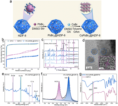
HZIF-8 is produced utilizing a method reported in prior literature.23 In order to achieve the formation of CsPbBr3 within the HZIF-8, a sequential deposition method was employed, also known as the ship-in-bottle strategy (Fig. 1(a)), to synthesize the composite material. In this approach, the as-synthesized HZIF-8 powder was immersed in a PbBr2 DMSO solution and allowed to remain for 1 hour to facilitate the entry of PbBr2 into the HZIF-8 pores. Subsequently, a DMSO wash was employed to remove any excess PbBr2 adhered to the surface of HZIF-8. The resulting PbBr2@HZIF-8 was then immersed in a CsBr DMSO solution. Finally, toluene was introduced to generate CsPbBr3 within the HZIF-8. To stabilize CsPbBr3, appropriate amounts of OA and OAm are added to the reaction system as organic stabilizers. After the synthesis process, the resulting material was centrifuged and washed with ethanol to obtain the final CsPbBr3@HZIF-8. The porosity of the conventional ZIF-8, HZIF-8, and 4%-CsPbBr3@HZIF-8 composites was characterized by N2 adsorption/desorption isotherm that is measured at 77 K, as exhibited in Fig. 1(b). The ZIF-8 displayed a typical type I, demonstrating a micro-porous structure.28 However, HZIF-8 and 4%-CsPbBr3@HZIF-8 displayed a combination of type I and IV isotherms, suggesting the coexistence of micro and mesopores.27 Similarly, the pore size distributions of samples align with this conclusion (Fig. S2, ESI†). The formation of a hierarchically porous structure not only enhances the affinity for the encapsulated guest but also promotes mass transfer during adsorption and catalysis processes.23,24 In Fig. 1(c), the PXRD (Powder X-ray diffraction) of CsPbBr3@HZIF-8 and HZIF-8 are analyzed. The patterns of the CsPbBr3@HZIF-8 sample exhibited good agreement with the characteristic patterns of the monoclinic CsPbBr3 phase (PDF# 18-0364).29 The intense peaks observed at 21.4°, 30.3°, 30.6°, 34.3°, 37.6° and 43.6°, which can be indexed to the (110), (002), (200), (201), (211) and (202) planes of the superior crystallinity CsPbBr3. Moreover, with the increase in the content of CsPbBr3, the intensity of PXRD peaks corresponding to CsPbBr3 gradually increases. Furthermore, the PXRD of ZIF-8 and HZIF-8 show no discernible difference in their crystal structures (Fig. S3, ESI†). In order to investigate the combination mode of the CsPbBr3 and HZIF-8, TEM (transmission electron microscopy) and HRTEM (high-resolution transmission electron microscopy) are utilized. Fig. 1(d) displays TEM pictures of 4%-CsPbBr3@HZIF-8, revealing that the CsPbBr3 (blue circle) is embedded within the HZIF-8 matrix. In the HRTEM shown in Fig. 1(d), lattice fringes exhibiting a spacing of 0.239 nm are observed, which corresponds well to the (211) planes of monoclinic CsPbBr3. Furthermore, the quasi-spherical morphology of 4%-CsPbBr3@HZIF-8 has been observed in Fig. S4 (ESI†). XPS (X-ray photoelectron spectroscopy) is utilized to characterize the synthesized composite material (Fig. 1(e) and (f)). According to the survey spectrum analysis, the identification of Zn, Cs, Pb, Br, N, and C elements in the synthesized 4%-CsPbBr3@HZIF-8 composite material is confirmed. The Pb 4f spectrum displayed two signals at 138.1 and 142.9 eV, which are associated with Pb2+ in CsPbBr3.30 Through Fourier transform infrared (FTIR) spectral analysis, we can obtain structural information and the chemical composition of samples, as depicted in Fig. 1(g). The FTIR spectra of 4%-CsPbBr3@HZIF-8 and HZIF-8 are compared, and the appearance of new absorption bands (2820 and 2923 cm−1), which is the distinctive peak of the C–H stretching vibration of the OA and OAm anchored on the surface of CsPbBr3.31 Collectively, these results provide strong evidence that the desired CsPbBr3@HZIF-8 composite material has been successfully constructed using a simple encapsulation method.3.2 Optical properties and energy band alignments
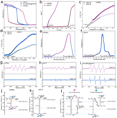
In order to study the electronic band arrangement and validate the Z-scheme charge transfer process of CsPbBr3@HZIF-8, UV-vis diffuse reflectance spectroscopy (DRS), electrochemical measurements, and electron spin resonance (ESR) are researched, as illustrated in Fig. 2. Absorption of light characteristics of HZIF-8, CsPbBr3, and 4%-CsPbBr3@HZIF-8 samples are determined by DRS, as depicted in Fig. 2(a). HZIF-8 displays an absorption band edge centered around 276 nm, while CsPbBr3 exhibits a distinct absorption band edge at 564 nm. However, the absorption behavior of the 4%-CsPbBr3@HZIF-8 heterojunction samples is found to be intermediate between HZIF-8 and CsPbBr3, indicating a strong electronic coupling between the two materials’ nanospheres. Based on the Tauc plots shown in Fig. 2(b), the bandgap (Eg) values of HZIF-8 and CsPbBr3, are confirmed as 4.7 eV and 2.3 eV, respectively.32 Furthermore, the Mott–Schottky plots in Fig. 2(c) and (d) allowed for the estimation of the flat-band (Ef) potentials of CsPbBr3 and HZIF-8 to be −1.14 V and −0.96 V versus the Ag/AgCl electrode (vs. Ag/AgCl), respectively. Similarly, the Mott–Schottky curve of CsPbBr3 and HZIF-8 indicated n-type characteristics of the catalyst due to the positive slope of the linear plot. Ef (vs. Ag/AgCl) is approximately 0.2 V more negative than the Efversus the normal hydrogen electrode (vs. NHE),33 and therefore, the reported Ef values of CsPbBr3 and HZIF-8 corresponded to −9.04 and 0.76 V (vs. NHE). Typically, for n-type semiconductors, the bottom of the conduction band (ECB) is about 0.1 V more negative than the Ef. As a result, the ECB of CsPbBr3 and HZIF-8 are ascertained to be 1.04 and 0.86 V (vs. NHE), respectively. According to the ECB = EVB − Eg formula, the EVB (valence band) of CsPbBr3 and HZIF-8 are calculated to be 1.26 and 3.37 V (vs. NHE), respectively. Additionally, the band structures of CsPbBr3 and HZIF-8 were investigated using ultraviolet photoelectron spectroscopy (UPS). In Fig. 2(e) and (f), the values of cutoff energy (Ecutoff) and Fermi energy (EFermi) are derived from distinctive tangent lines representing the high and low binding energy domains, respectively.34 The equations (EVB = hν − Ecutoff + EFermi (eV), ECB = EVB − Eg (eV), E(RHE,V) = E(eV) − 4.44) employed yield the valence band (EVB) and conduction band (ECB) of the samples.35,36 Here, the symbol hν denotes the incident photon energy of He I (21.2 eV). As observed in Fig. 2(e) and (f), the Ecutoff values for CsPbBr3 and HZIF-8 are 16.98 and 16.30 eV, respectively. Additionally, the EFermi values for CsPbBr3 and HZIF-8 are 1.38 and 3.22 eV, respectively. Consequently, the EVB values of CsPbBr3 and HZIF-8 are established at 1.16 V and 3.68 V, respectively, while the ECB values of CsPbBr3 and HZIF-8 are measured at −1.14 V and −1.02 V. In alignment with this, the anticipated band alignments of the individual components are shown in Fig. S5 (ESI†), similar to the M–S outcomes. The presented data provide direct evidence for the band structure presented in Fig. 2(j) and (k). It is predicted that an internal electrostatic field emerges at the interface between HZIF-8 and CsPbBr3, causing photogenerated electrons to be driven from HZIF-8 to CsPbBr3, ultimately resulting in the establishment of a Z-scheme heterojunction. In order to validate the energy band structure and confirm the creation of a Z-scheme system, electron spin resonance (ESR) examination is conducted to detect spin-active species, including ˙O2− and ˙OH, employing 5,5-dimethyl-1-pyrroline N-oxide (DMPO) as a trapping agent.37 In Fig. 2(g), only signals associated with the DMPO-˙O2− are observed for CsPbBr3 as its EVB (1.26 V vs. NHE) is not sufficiently positive to oxidize H2O to ˙OH. On HZIF-8 in Fig. 2(h), both DMPO-˙O2− and DMPO-˙OH spectral features are noted since the ECB (0.86 V vs. NHE) is more positive than the redox potential of O2/˙O2− (−0.33 V vs. NHE), the EVB (3.37 V vs. NHE) demonstrates a more negative tendency than H2O/˙OH (1.99 V vs. NHE). As for CsPbBr3@HZIF-8, Fig. 2(i) shows the typical signals of DMPO-˙O2− and DMPO-˙OH. Of note, the intensity of the signals corresponding to DMPO-˙O2− and DMPO-˙OH are higher in the heterojunction sample compared to the two single-phase samples. The increased signal intensity indicates a higher accumulation of holes in the EVB of HZIF-8 and electrons in the ECB of CsPbBr3. Meanwhile, these findings effectively rule out the feasibility of conventional type II heterojunctions in the composite materials mentioned above (Fig. 2(l)).37,38 The fabrication of the Z-scheme charge transfer process in CsPbBr3@HZIF-8 may thus be validated based on the studies presented above (Fig. 2(j)). In addition to encouraging appropriate spatial charge carrier separation, this Z-scheme heterojunction also achieves the higher redox capacity for the entire system.3.3 Photocatalytic performance on the degradation of TCH
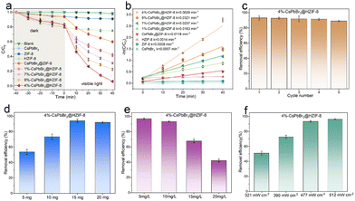
Tetracycline hydrochloride (TCH), an omnipresent recalcitrant organic contaminant, is ubiquitously encountered in diverse wastewater streams, encompassing pharmaceutical effluents, livestock breeding wastewater, and urban sewage. Hence, the central objective of this study was to scrutinize the photocatalytic degradation of TCH as the focal compound of interest. The initial concentration of TCH deionized solution used in this study is 10 mg L−1 (30 mL), and the visible light (fitted with a 420 nm filter) intensity was 477 mW cm−2. Fig. 3(a) illustrates the adsorption and degradation performance of various photocatalysts (15 mg). To ensure the adsorption–desorption equilibrium of the samples, all materials are stirred in the TCH solution under darkness for 40 minutes before visible light irradiation. It is evident that the pristine CsPbBr3 shows no adsorption capacity for TCH molecules, which can be attributed to the disruption of the structure of CsPbBr3 in water. On the contrary, ZIF-8 shows significant adsorption performance after 40 minutes of dark reaction, which was related to the abundant porosity of ZIF-8. Simultaneously, both ZIF-8 and CsPbBr3@ZIF-8 exhibit nearly identical adsorption performance. The adsorption capability of HZIF-8 was better than that of ZIF-8. This may be assigned to the fact that HZIF-8 has more available adsorption active sites and a hierarchical pore structure that enhances the rate of mass transfer of TCH. Meanwhile, the similar adsorption capacity of HZIF-8 and CsPbBr3@HZIF-8 is advantageous for the subsequent photocatalytic reaction. Furthermore, the absence of a photocatalyst resulted in negligible photodegradation, indicating the outstanding photostability of TCH. Regarding ZIF-8 and HZIF-8, only 4% of TCH is removed in 40 min, suggesting very low activity for visible light-induced degradation. This is associated with the wide energy gap and low visible-light absorption intensity of ZIF-8 and HZIF-8. CsPbBr3 did not exhibit any degradation activity against the pollutants, likely due to structural destruction. As for CsPbBr3@ZIF-8, 40% of TCH is removed in 40 min. Under the same conditions, the hierarchically porous Z-scheme CsPbBr3@HZIF-8 heterostructure exhibited a significant improvement. The removal efficiency of TCH was 58%, 70%, 94% and 78% over the 1%-CsPbBr3@HZIF-8, 7%-CsPbBr3@HZIF-8,4%-CsPbBr3@HZIF-8 and 9%-CsPbBr3@HZIF-8, respectively. Moreover, the kinetics of TCH photodegradation over the prepared catalysts was evaluated by fitting the concentration–time curve using a pseudo-first-order equation, as depicted in Fig. 3(b). Among the tested catalysts, 4%-CsPbBr3@HZIF-8 exhibited the highest rate constant for TCH degradation, with a value of 0.0629 min−1. This rate constant was approximately 44 and 89 times higher than those of HZIF-8 (0.0014 min−1) and CsPbBr3 (0.0007 min−1), respectively. The successful construction of hierarchically porous Z-scheme heterojunctions is demonstrated as an efficient approach for optimizing the photocatalytic performance of the photocatalyst. The improved performance of the CsPbBr3@HZIF-8 is due to the successful separation and transfer of photogenerated charge carriers, as well as the enhanced visible light absorption capacity and CsPbBr3 stability. Compared to previously reported metal halide perovskite photocatalysts, the CsPbBr3@HZIF-8 photocatalyst developed in this study demonstrated competitive performance in the degradation of TCH (Table S1, ESI†). Ensuring the stability and reusability of catalysts is a crucial aspect of practical applications in photocatalytic degradation. In the case of 4%-CsPbBr3@HZIF-8, the visible light photocatalytic performance decreased by only 4% after four cycles of TCH degradation, indicating that the composites have high visible light photocatalytic stability (Fig. 3(c)). Furthermore, the PXRD and SEM results showed the crystal structure of 4%-CsPbBr3@HZIF-8 remained stable following four cycles of TCH degradation (Fig. S6 and S7, ESI†), signifying high structural stability. In addition to assessing the visible-light responsive photocatalysis performance, this work also investigated important experimental parameters such as sample dosage, the initial concentrations of the TCH solution, and visible-light intensity. Fig. 3(d) shows the efficiency of visible light photocatalytic degradation of TCH using different doses of CsPbBr3@HZIF-8 (5–20 mg) while keeping other operational parameters constant. A notable observation is that CsPbBr3@HZIF-8 with dosages of 15 mg exhibits the highest visible-light photocatalytic performance. The excessive amounts of photocatalyst-suspended solids can reduce the light utilization and decrease the solution transparency, which may explain the highest photocatalytic efficiency at 15 mg instead of 20 mg. The concentration of pollutants in actual wastewater is a critical variable parameter that can significantly impact the photocatalytic activity of photocatalysts. In this study, the influence of initial TCH concentration was investigated across the range of 5–20 mg L−1, which is relevant to real-world wastewater conditions. The photocatalytic degradation efficiency of TCH exhibited notable results when exposed to 5 mg L−1 and 10 mg L−1 initial concentrations, reaching 97.0% and 93.3% degradation efficiency, respectively, as revealed in Fig. 3(e). As the initial TCH level increased to 15 and 20 mg L−1, the degradation efficiency reduced to 67.6% and 42.0%, respectively, indicating that higher concentrations of TCH had a notable detrimental effect on the photodegradation process. As illustrated in Fig. 3(f), the visible-light intensity had a notable influence on the photocatalytic activity of the 4%-CsPbBr3@HZIF-8. In general, it was observed that the visible-light photocatalytic performance exhibited an increasing trend with the increment of visible-light intensity. Note that the photocatalytic performance of the remains consistent when exposed to visible-light intensities of 477 mW cm2 and 512 mW cm2, indicating comparable performance at these levels. Based on these findings, it can be concluded that the optimal visible-light intensity for this work may be determined to be 477 mW cm2. To verify the selectivity of TCH degradation, a mixed solution of 30 mL containing both TCH (5 mg L−1) and rhodamine B (RhB) (5 mg L−1) (TCH/methylene blue (MB), TCH/oxytetracycline (OTC)) was chosen as the target pollutants while keeping other conditions unchanged. As shown in Fig. S8 (ESI†), simultaneous degradation of TCH and RhB was achievable within the CsPbBr3@HZIF-8 systems. Similarly, TCH and MB, as well as TCH and OTC, can also be simultaneously degraded. For a more comprehensive assessment of the 4%-CsPbBr3@HZIF-8 efficiency in the photocatalytic process, model pollutants such as RhB, MB, and OTC were chosen at equivalent concentrations for conducting degradation experiments through photocatalysis. As depicted in Fig. S9 (ESI†), the utilization of 4%-CsPbBr3@HZIF-8 resulted in remarkably high removal efficiencies: 98% for RhB (30 min), 95% for MB (30 min), and 91% for OTC (40 min). This substantial efficacy underscores 4%-CsPbBr3@HZIF-8's capacity to degrade diverse dyes and pharmaceutical compounds effectively.3.4 Effect of inorganic anions on the degradation of TCH
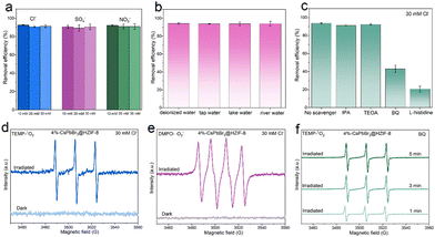
In practical wastewater systems, the concentration of inorganic salts and the coexistence of different inorganic salts are likely to be the main factors exacerbating the challenges in TCH wastewater treatment.8,9 To investigate the performance of 4%-CsPbBr3@HZIF-8 in high-salinity water, the removal of TCH is conducted on the samples under varying concentrations (10, 20, 30 mM) of different anions (Cl−, SO4−, and NO3−). As presented in Fig. 4(a), all anions did not show a notable impact on the degradation rate of TCH at any tested concentration. In addition, the effects of three additional water matrices on the photocatalytic activity are investigated. Water samples were collected from different sources, including tap water (43°49′50′′N, 125°18′48′′E, Changchun, jilin, Fig. S10, ESI†), river water (43°49′58′′N, 125°21′26′′E, Changchun, jilin, Fig. S11, ESI†) and lake water (43°51′8′′N, 125°18′20′′E, Changchun, jilin, Fig. S12, ESI†). The 4%-CsPbBr3@HZIF-8 composite exhibited remarkable degradation performance even under real-world water conditions, indicating its promising practical applications. To investigate the dominant active species during the decomposition process in salt-containing systems, quenching experiments are conducted with the coexistence of 30 mM Cl−. Herein, isopropanol (IPA), triethanolamine (TEOA), benzoquinone (BQ), and L-histidine are utilized to capture hydroxyl radicals (˙OH), holes (h+), superoxide radicals (˙O2−), and singlet oxygen (1O2), respectively.39,40 In Fig. 4(c), 91.3% and 92.3% degradation efficiency are observed after the addition of IPA (0.1 mM) and TEOA (0.1 mM), respectively. When BQ (0.1 mM) and L-histidine (0.1 mM) are added to the photocatalytic system, degradation efficiency declines from 93.7% to 43.0%, and 20.7%, respectively. Therefore, ˙O2− and 1O2 are the predominant active species, while ˙OH and h+ do not participate in the photocatalytic reaction. To validate the outcomes of the radical capture experiments, electron paramagnetic resonance (EPR) spectroscopy was implemented to detect ˙O2− and 1O2 in the presence of 30 Mm Cl−. During the exposure to light, 5,5-dimethyl-1-pyrroline-N-oxide (DMPO) was utilized as the scavenger for ˙O2−, whereas 2,2,6,6-tetramethylpiperidine (TEMP) acted as the scavenger for 1O2. Fig. 4(d) clearly illustrates the absence of signals in the dark, whereas distinctive peaks related to DMPO-˙O2− are detected under visible light irradiation in a methanol medium. Evidently, characteristic peaks corresponding to TEMP-1O2 with an intensity ratio of 1![[thin space (1/6-em)]](https://www.rsc.org/images/entities/char_2009.gif) :
:![[thin space (1/6-em)]](https://www.rsc.org/images/entities/char_2009.gif) 1
1![[thin space (1/6-em)]](https://www.rsc.org/images/entities/char_2009.gif) :
:![[thin space (1/6-em)]](https://www.rsc.org/images/entities/char_2009.gif) 1 are detected under light irradiation (Fig. 4(e)). The obtained results align with scavenger experiments conducted on 4%-CsPbBr3@HZIF-8. Understanding the pathways of 1O2 generation is crucial for comprehending the mechanism of photocatalytic reactions. As we know, in the photo-activation of molecular oxygen, two potential pathways exist for the generation of 1O2.41 The first involves energy transfer from excited semiconductors to the ground state O2, leading to the production of 1O2. Alternatively, O2 can initially acquire a photoexcited electron to form ˙O2−, which is subsequently oxidized to ˙O2− by photogenerated holes residing in the valence band. To elucidate the generation pathway of 1O2, EPR spectroscopy is employed in the presence of BQ, which acts as a ˙O2− scavenger in photocatalysis. As depicted in Fig. 4(f), the EPR signal strength of 1O2 in the presence of BQ not only does not decrease but actually increases with increasing irradiation time. This experimental finding establishes that the generation of 1O2 cannot be ascribed to the ˙O2− species, thus providing evidence that 1O2 is produced through an energy transfer pathway.12
1 are detected under light irradiation (Fig. 4(e)). The obtained results align with scavenger experiments conducted on 4%-CsPbBr3@HZIF-8. Understanding the pathways of 1O2 generation is crucial for comprehending the mechanism of photocatalytic reactions. As we know, in the photo-activation of molecular oxygen, two potential pathways exist for the generation of 1O2.41 The first involves energy transfer from excited semiconductors to the ground state O2, leading to the production of 1O2. Alternatively, O2 can initially acquire a photoexcited electron to form ˙O2−, which is subsequently oxidized to ˙O2− by photogenerated holes residing in the valence band. To elucidate the generation pathway of 1O2, EPR spectroscopy is employed in the presence of BQ, which acts as a ˙O2− scavenger in photocatalysis. As depicted in Fig. 4(f), the EPR signal strength of 1O2 in the presence of BQ not only does not decrease but actually increases with increasing irradiation time. This experimental finding establishes that the generation of 1O2 cannot be ascribed to the ˙O2− species, thus providing evidence that 1O2 is produced through an energy transfer pathway.12
3.5 Photoinduced charge separation and transfer dynamics
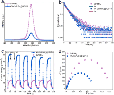
To further uncover the charge transfer and separation behaviors in the Z-scheme, a photoelectrochemical test is conducted, as shown in Fig. 5. In the meantime, this experimental approach offers a robust and rigorous means of characterizing the photocatalytic behavior of the material. The photoluminescence (PL) indicates that the rates of recombination of photoinduced electron–hole pairs in the 4%-CsPbBr3@HZIF-8 heterostructure are inhibited, as evidenced by the weaker peak compared to those of CsPbBr3 (Fig. 5(a)).27,42 The time-resolved photoluminescence (TRPL) is utilized to investigate the Z-scheme CsPbBr3@HZIF-8 heterostructure charge transfer dynamics in detail (Fig. 5(b)). The technique is widely regarded as a powerful method for revealing the mechanism of charge transport in semiconductors. By fitting the decay curves using a model of two exponential functions (as shown in Table S2, ESI†), the average TRPL lifetimes of CsPbBr3 and CsPbBr3@HZIF-8 are determined to be 40.99 and 28.35 ns, respectively. Notably, CsPbBr3@HZIF-8 exhibits a shorter average lifetime compared to pristine CsPbBr3.42 This is attributed to the electron transfer from the conduction band of HZIF-8 to the valence band of CsPbBr3, which promotes surface photocatalytic reactions. To provide evidence of the enhancing charge separation between HZIF-8 and CsPbBr3, photocurrent response and electrochemical impedance spectroscopy (EIS) experimental data are performed. As presented in Fig. 5(c), the superior photocurrent density of CsPbBr3@HZIF-8 as compared to CsPbBr3, indicates more efficient charge separation in CsPbBr3@HZIF-8.42,43 Subsequently, EIS is conducted to investigate the migration behaviors of photogenerated carriers (Fig. 5(d)). The formation of a heterojunction in CsPbBr3@HZIF-8 is evidenced by the smaller charge transfer resistance observed in comparison to pure CsPbBr3.43 The combination of the results obtained, as well as the EPR results, provides solid evidence for the formation of a Z-scheme CsPbBr3@HZIF-8 heterostructure.3.6 TCH degradation pathway
To gain a more thorough insight into the photocatalytic degradation process of HTC induced by the 4%-CsPbBr3@HZIF-8 heterojunction, the intermediates generated during the reaction were analyzed employing high-performance liquid chromatography–mass spectrometry (HPLC-MS). Nine distinct intermediate products (P1–P9) were identified during the visible light photocatalytic degradation of TCH, exhibiting respective m/z values of 431(P1), 416 (P2), 298 (P3), 272 (P4), 429 (P5), 348 (P6), 292 (P7),194 (P8) and 174 (P9). The identified intermediates are documented and presented in Fig. S13 and Table S3 (ESI†). Based on the identified intermediates, two potential transformation mechanisms for TCH photodegradation were proposed and depicted in Fig. 6. TCH initially underwent hydrolysis in the aqueous medium, leading to the generation of tetracycline. Three primary reaction pathways were identified during the photocatalytic process: (1) the cleavage of the carbon–carbon double bond on the benzene ring, (2) the modification of hydroxyl groups adjacent to the methyl group in the cyclohexanone moiety, and (3) the transformation of dimethylamino groups into amino groups.44 Subsequently, the active species attacked the molecules, leading to the formation of smaller molecular intermediates through deamination, decarbonylation, dehydroxylation, and ring-opening reactions. Ultimately, the initial stage TCH is anticipated to undergo mineralization to H2O, CO2 and other inorganic compounds in the presence of reactive species, thus completing the breakdown of TCH. It was imperative to take into account the potential toxicities of the by-products generated during the degradation of TCH. The acute and developmental toxicities of the degradation products were evaluated using Toxicity Estimation Software (TEST), employing the quantitative structure–activity relationship (QSAR) method.45Fig. 6(b) elucidates the Daphnia magna LC50 (48 h) outcomes, underscoring a notable reduction in toxicity of the degraded small molecule intermediates in comparison to TCH, except for P2. Moreover, the removal process led to a decrease in developmental toxicity for the TCH intermediates, with the exceptions being P2 and P4, as illustrated in Fig. 6(c). From the outcomes of the toxicity assessment, it is evident that the CsPbBr3@HZIF-8 system is proficient in efficiently detoxifying the TCH solution. This is substantiated by the fact that, following photocatalysis, the majority of intermediates exhibit lower toxicity compared to TCH.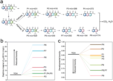 | ||
| Fig. 6 Possible degradation pathways of TCH in the CsPbBr3@HZIF-8 system. Toxicity assessment (b) Daphnia magna LC50 (48 h), and (c) developmental toxicity. | ||
3.7 Possible photocatalytic mechanism
Based on the comprehensive findings obtained from our experimental investigations and previous literature, we propose a plausible mechanism to elucidate the observed enhancement in photocatalytic activity over a hierarchically porous Z-scheme CsPbBr3@HZIF-8 heterostructure (Fig. 7). First of all, the rational design of the hierarchically porous CsPbBr3@HZIF-8 increases the contact area, providing more reaction sites for efficient photocatalytic degradation of target pollutants. Secondly, according to the Z-scheme heterojunction pattern, the photoexcited electrons (e−) exhibit a preference for migration from the ECB of HZIF-8 to the EVB of CsPbBr3 under visible light irradiation, while recombination events occur between them. As a result, the accumulation of e− on the ECB of CsPbBr3 and holes (h+) on the EVB of HZIF-8 results in a strong redox ability. The O2 molecules adsorbed on the surface of HZIF-8 combine with the accumulated e− to form ˙O2−. The h+ in the EVB of HZIF-8 participates in the oxidation reaction of H2O to generate ˙OH− with strong oxidizing ability. In addition to the generation of ˙O2−, a fraction of the photoexcited CsPbBr3 undergoes an intersystem crossing (ISC) process, transitioning from singlet excited states to triplet excited states.15 Subsequently, energy transfer occurs, thus changing the O2 electronic spin state (spin flip) to generate 1O2.46 Finally, the resulting ˙O2− and 1O2 participate in the degradation process of TCH.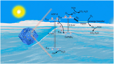 | ||
| Fig. 7 The possible photocatalytic mechanism of hierarchically porous Z-scheme CsPbBr3@HZIF-8 heterojunctions. | ||
4. Conclusions
In summary, a series of hierarchically porous Z-scheme heterojunctions composed of CsPbBr3 and HZIF-8 are fabricated by a ship-in-bottle strategy. The hierarchically porous Z-scheme heterojunction CsPbBr3@HZIF-8 not only facilitates the mass transfer and enrichment of pollutants but also accelerates the transfer of carriers between HZIF-8 and CsPbBr3, leading to enhanced generation of reactive oxygen species. Additionally, CsPbBr3 acts as a photosensitizer for efficient energy transfer, leading to the generation of 1O2 with enhanced resistance to ion interference. Consequently, the optimized catalyst (4%-CsPbBr3@HZIF-8) demonstrates the highest visible photocatalytic performance in the degradation of TCH (94% in 40 min), demonstrating consistent efficiency in deionized water, high-salinity water, and real water matrices. The catalyst also displays remarkable stability and reusability. Moreover, comprehensive investigation and elucidation of the photocatalytic reaction mechanisms are conducted, including the analysis of charge carrier transfer behaviors, generation of reactive species, and identification of degradation intermediate products of TCH. This work provides new insights into the development of advanced photocatalysts for the treatment of pollutants in high-salinity water.Author contributions
The manuscript was written through the contributions of all authors.Conflicts of interest
There are no conflicts of interest to declare.Acknowledgements
This work was financially supported by the NSFC of China (no. 22271023, 21971032 and 22101067), the Education Department of Jilin Province (no. JJKH20221153KJ), and the Jilin Provincial Department of Science and Technology (no. 20230508108RC).References
- O. Baaloudj, I. Assadi, N. Nasrallah, A. El Jery, L. Khezami and A. A. Assadi, J. Water Process. Eng., 2021, 42, 102089 CrossRef.
- J. Scaria, K. V. Anupama and P. V. Nidheesh, Sci. Total Environ., 2021, 771, 145291 CrossRef CAS PubMed.
- S. Wu, Y. Lin and Y. H. Hu, J. Mater. Chem. A, 2021, 9, 2592–2611 RSC.
- T. Ji, H. Zhang, S. J. Shah, Y. Wang, W. Gong, R. Wang, L. Pan, H. Ji, G. Chen, Z. Zhao and Z. Zhao, J. Mater. Chem. A, 2022, 10, 22571–22583 RSC.
- Q. Li and F. Li, Chem. Eng. J., 2021, 421, 129915 CrossRef CAS.
- Y. Nosaka and A. Y. Nosaka, Chem. Rev., 2017, 117, 11302–11336 CrossRef CAS PubMed.
- R. Luo, M. Li, C. Wang, M. Zhang, M. A. Nasir Khan, X. Sun, J. Shen, W. Han, L. Wang and J. Li, Water Res., 2019, 148, 416–424 CrossRef CAS PubMed.
- Z. Wang, J. Huang, W. Wang, X. Wang, Y. Wang, B. Gao and Q. Li, Chem. Eng. J., 2023, 466, 143194 CrossRef CAS.
- Y. Chi, S. Xu, M. Li, M. He, H. Yu, L. Li, Q. Yue and B. Gao, J. Hazard. Mater., 2020, 396, 122670 CrossRef CAS PubMed.
- Z. Wang, Z. Liu, J. Huang, Y. Chen, R. Su, J. He, G. Lv, B. Gao, W. Zhou, Y. Wang, Z. Wang and Q. Li, Chem. Eng. J., 2022, 440, 135883 CrossRef CAS.
- R. Luo, M. Li, C. Wang, M. Zhang, M. A. Nasir Khan, X. Sun, J. Shen, W. Han, L. Wang and J. Li, Water Res., 2019, 148, 416–424 CrossRef CAS PubMed.
- L.-S. Zhang, X.-H. Jiang, Z.-A. Zhong, L. Tian, Q. Sun, Y.-T. Cui, X. Lu, J.-P. Zou and S.-L. Luo, Angew. Chem., Int. Ed., 2021, 60, 21751–21755 CrossRef CAS PubMed.
- K. Ren, S. Yue, C. Li, Z. Fang, K. A. M. Gasem, J. Leszczynski, S. Qu, Z. Wang and M. Fan, J. Mater. Chem. A, 2022, 10, 407–429 RSC.
- W. Gong, Y. Li, Y. Yang, H. Guo and X. Niu, J. Mater. Chem. C, 2023, 11, 6963–6970 RSC.
- K. Gu, Y. Wang, J. Shen, J. Zhu, Y. Zhu and C. Li, ChemSusChem, 2020, 13, 682–687 CrossRef CAS PubMed.
- H. Shankar, S. Ghosh and P. Kar, J. Mater. Chem. C, 2022, 10, 11532–11554 RSC.
- P. Chen, W.-J. Ong, Z. Shi, X. Zhao and N. Li, Adv. Funct. Mater., 2020, 30, 1909667 CrossRef CAS.
- H. Huang, D. Verhaeghe, B. Weng, B. Ghosh, H. Zhang, J. Hofkens, J. A. Steele and M. B. J. Roeffaers, Angew. Chem., Int. Ed., 2022, 134, e202203261 CrossRef.
- E. M. Akinoglu, D. A. Hoogeveen, C. Cao, A. N. Simonov and J. J. Jasieniak, ACS Nano, 2021, 15, 7860–7878 CrossRef CAS PubMed.
- J. Li, H. Wang, X. Yuan, J. Zhang and J. W. Chew, Coord. Chem. Rev., 2020, 404, 213116 CrossRef CAS.
- H. Dai, X. Yuan, L. Jiang, H. Wang, J. Zhang, J. Zhang and T. Xiong, Coord. Chem. Rev., 2021, 441, 213985 CrossRef CAS.
- W. Mo, Z. Fan, S. Zhong, W. Chen, L. Hu, H. Zhou, W. Zhao, H. Lin, J. Ge, J. Chen and S. Bai, Small, 2023, 19, 2207705 CrossRef CAS PubMed.
- N. Singh, S. Ahmed, A. Fakim, S. Qutub, O. Alahmed, O. E. Tall, O. Shekhah, M. Eddaoudi and N. M. Khashab, Chem. Sci., 2020, 11, 11280–11284 RSC.
- Z. Zhang, Y. Chen, C. Hu, C. Zuo, P. Wang, W. Chen and T. Ao, Environ. Res., 2021, 198, 111254 CrossRef CAS PubMed.
- H. Sun, F. Yuan, S. Jia, X. Zhang and W. Xing, J. Hazard. Mater., 2023, 445, 130460 CrossRef CAS PubMed.
- K. S. Park, Z. Ni, A. P. Côté, J. Y. Choi, R. Huang, F. J. Uribe-Romo, H. K. Chae, M. O’Keeffe and O. M. Yaghi, Proc. Natl. Acad. Sci. U. S. A., 2006, 103, 10186–10191 CrossRef CAS PubMed.
- Z.-C. Kong, J.-F. Liao, Y.-J. Dong, Y.-F. Xu, H.-Y. Chen, D.-B. Kuang and C.-Y. Su, ACS Energy Lett., 2018, 3, 2656–2662 CrossRef CAS.
- M. Thommes, K. Kaneko, A. V. Neimark, J. P. Olivier, F. Rodriguez-Reinoso, J. Rouquerol and K. S. W. Sing, Pure Appl. Chem., 2015, 87, 1051–1069 CrossRef CAS.
- H. Kim, S.-R. Bae, T. H. Lee, H. Lee, H. Kang, S. Park, H. W. Jang and S. Y. Kim, Adv. Funct. Mater., 2021, 31, 2102770 CrossRef CAS.
- Z. Wang, R. Fu, F. Li, H. Xie, P. He, Q. Sha, Z. Tang, N. Wang and H. Zhong, Adv. Funct. Mater., 2021, 31, 2010009 CrossRef CAS.
- G.-Y. Qiao, D. Guan, S. Yuan, H. Rao, X. Chen, J.-A. Wang, J.-S. Qin, J.-J. Xu and J. Yu, J. Am. Chem. Soc., 2021, 143, 14253–14260 CrossRef CAS PubMed.
- Y. Zhang and S.-J. Park, Chem. Eng. J., 2019, 369, 353–362 CrossRef CAS.
- S.-H. Guo, X.-J. Qi, H.-M. Zhou, J. Zhou, X.-H. Wang, M. Dong, X. Zhao, C.-Y. Sun, X.-L. Wang and Z.-M. Su, J. Mater. Chem. A, 2020, 8, 11712–11718 RSC.
- Y. Liu, H. Wang, K. Chen, T. Yang, S. Yang and W. Chen, ACS Appl. Mater. Interfaces, 2019, 11, 9573–9582 CrossRef CAS PubMed.
- D. Kim and K. Yong, Appl. Catal., B, 2021, 282, 119538 CrossRef CAS.
- X. She, J. Wu, H. Xu, J. Zhong, Y. Wang, Y. Song, K. Nie, Y. Liu, Y. Yang, M.-T. F. Rodrigues, R. Vajtai, J. Lou, D. Du, H. Li and P. M. Ajayan, Adv. Energy Mater., 2017, 7, 1700025 CrossRef.
- Y. Jiang, J.-F. Liao, H.-Y. Chen, H.-H. Zhang, J.-Y. Li, X.-D. Wang and D.-B. Kuang, Chem, 2020, 6, 766–780 CAS.
- X. He, Y. Ding, Z. Huang, M. Liu, M. Chi, Z. Wu, C. U. Segre, C. Song, X. Wang and X. Guo, Angew. Chem., Int. Ed., 2023, 135, e202217439 CrossRef.
- F. Deng, L. Zhao, X. Luo, S. Luo and D. D. Dionysiou, Chem. Eng. J., 2018, 333, 423–433 CrossRef CAS.
- K. Gao, L. Hou, X. An, D. Huang and Y. Yang, Appl. Catal., B, 2023, 323, 122150 CrossRef CAS.
- Z. Shen, Z. Luo, J. Chen and Y. Li, Adv. Funct. Mater., 2023, 33, 2213935 CrossRef CAS.
- Y.-F. Mu, W. Zhang, G.-X. Dong, K. Su, M. Zhang and T.-B. Lu, Small, 2020, 16, 2002140 CrossRef CAS PubMed.
- J. Wang, J. Wang, N. Li, X. Du, J. Ma, C. He and Z. Li, ACS Appl. Mater. Interfaces, 2020, 12, 31477–31485 CrossRef CAS PubMed.
- J. Wang, D. Zhi, H. Zhou, X. He and D. Zhang, Water Res., 2018, 137, 324–334 CrossRef CAS PubMed.
- Z. Cai, X. Hao, X. Sun, P. Du, W. Liu and J. Fu, Water Res., 2019, 162, 369–382 CrossRef CAS PubMed.
- C. Cheng, B. Zhu, B. Cheng, W. Macyk, L. Wang and J. Yu, ACS Catal., 2023, 13, 459–468 CrossRef CAS.
Footnote |
| † Electronic supplementary information (ESI) available. See DOI: https://doi.org/10.1039/d3tc02493h |
| This journal is © The Royal Society of Chemistry 2023 |

