Electrolytes for electrochemical energy storage
Lan
Xia
 a,
Linpo
Yu
 a,
Di
Hu
a and
George Z.
Chen
 *ab
*ab
aDepartment of Chemical and Environmental Engineering, and Centre for Sustainable Energy Technologies, Faculty of Science and Engineering, University of Nottingham Ningbo China, Ningbo, 315100, China
bDepartment of Chemical and Environmental Engineering, Faculty of Engineering, University of Nottingham, Nottingham, NG7 2RD, UK. E-mail: george.chen@nottingham.ac.uk
First published on 3rd January 2017
Abstract
An electrolyte is a key component of electrochemical energy storage (EES) devices and its properties greatly affect the energy capacity, rate performance, cyclability and safety of all EES devices. This article offers a critical review of the recent progress and challenges in electrolyte research and development, particularly for supercapacitors and supercapatteries, rechargeable batteries (such as lithium-ion and sodium-ion batteries), and redox flow batteries (including fuel cells in a broad sense). The review will focus on liquid electrolytes, including aqueous and organic electrolytes, ionic liquids and molten salts. The influence of electrolyte properties on the performances of different EES devices is discussed in detail.
Linpo Yu is a Senior Research Fellow in Electrochemistry at the University of Nottingham Ningbo China. He is a member of the Royal Society of Chemistry. He received his BSc in Chemistry and PhD in Physical Chemistry (Electrochemistry) from Wuhan University in 2003 and 2008, respectively. He was a Research Assistant at Suzhou Institute of Nano-Tech and Nano-Bionics, CAS from 2008 to 2013. Then, he carried out postdoctoral research at the University of Nottingham in the UK for 2 years until he joined the University of Nottingham Ningbo China in 2015. His main research interests include the supercapacitor and supercapattery electrode materials, ionic liquid electrolytes, and thermochromic materials. |
Di Hu is assistant professor of chemical engineering in the University of Nottingham Ningbo Campus. His primary research background lies in the electrochemical production of pure metals and metal alloys via molten salt electrolysis. Dr Di Hu completed his BEng degree in Chemical Engineering and Technology at the China University of Mining and Technology (Beijing) in July 2006, and MSc and PhD degrees in Chemical Engineering at the University of Nottingham in December 2007 and 2011, respectively. His PhD research, on the subject of near-net-shape production of titanium alloy products via molten salt electrolysis, was supervised by Prof. George Z. Chen. |
George Zheng Chen (http://www.nottingham.ac.uk/~enzgzc), CChem, FRSC, FRSA, FIMMM, is professor of electrochemical technologies in both the Nottingham and Ningbo campuses of the University of Nottingham. He received both his Teaching Diploma (1981, Jiujiang Teacher Training College) and MSc (1985, Fujian Normal University, Prof. Qixin Zhang) in China. After obtaining his PhD in 1992 from University of London (Imperial College, Prof. John Albery, FRS), he worked in the Universities of Oxford (1992–1994), Leeds (1994–1996) and Cambridge (1996–2003, Darwin), and in Jiangxi (1985–1988) and Wuhan (2000–2010, invited position) Universities. His research aims at electrochemical and liquid salt innovations for materials, energy and environment, producing 600+ documented outputs, including the Fray-Farthing-Chen Cambridge Process. |
1. Introduction
Great concerns are growing regarding the accelerating exhaustion of fossil resources, mainly consumed in various forms of energy, and the associated climate and environmental issues, creating a great demand for energy storage devices at different scales. Of all ongoing developments, electrochemical energy storage (EES) technologies have attracted worldwide attention for portable consumer products, electric or hybrid electric vehicles and integration with the power grid and renewable energy sources. These uses are based on the fact that EES devices, e.g. rechargeable batteries, supercapacitors and redox flow batteries (including fuel cells in a broad sense), are manufactured in units or modules which can offer flexible combinations to meet the demands of high energy capacity, fast charging–discharging, improved safety, and long service life.1–9Nevertheless, EES also faces challenges. For example, as a relatively new member of the EES family, electric double layer capacitors (EDLCs) store energy through the electrostatic interaction between electrodes and ions in the electrolyte. They offer fast dis-/charging capability (i.e. high power capability, >10 kW kg−1), high energy efficiency (close to 100%), and long cycle life (>500![[thin space (1/6-em)]](https://www.rsc.org/images/entities/char_2009.gif) 000 cycles), and are promising for advanced and highly efficient energy storage management. However, compared to rechargeable batteries, including redox flow batteries, EDLCs have much lower energy capacity (usually <30 W h kg−1 in aqueous devices).
000 cycles), and are promising for advanced and highly efficient energy storage management. However, compared to rechargeable batteries, including redox flow batteries, EDLCs have much lower energy capacity (usually <30 W h kg−1 in aqueous devices).
It is well known that raising the operating voltage is an effective strategy to increase both the energy and power density of EES devices.10–12 Such an approach needs new electrode and electrolyte materials that are physically, chemically, and particularly electrochemically stable against the high operating voltage. Specifically for new liquid electrolytes, they need to offer low or zero flammability and beneficial interactions with the electrode materials, in addition to other properties as discussed below. Surprisingly, compared to the active and dynamic research on electrode materials, research on electrolytes has received relatively less attention.13–18
An electrolyte is an indispensable constituent, liquid in most cases, in all types of EES devices and helps conduct electricity by means of transportation of ions, but not electrons. Because the electrolyte is placed between, and in close interaction with, the positive electrode (positrode) and the negative electrode (negatrode), its identification is the key to a safe and high performance EES device. (Note: the use of cathode and anode to describe the electrodes in rechargeable EES devices, lithium ion batteries in particular, is inappropriate and confusing because the same positrode is an anode in charging but a cathode in discharging. However, the positrode retains its positive polarity in both the charging and discharging processes. The case is similar for the negatrode.)
Basically, an electrolyte is an ionic conductor but an electronic insulator, and it is practically either a solid or more often a liquid which usually works with a porous membrane or gel in EES devices. A liquid electrolyte commonly refers to a solution comprising salts and solvents, and functional additives, but it can also be a pure liquid salt, such as an ionic liquid or a molten salt. In accordance with the principle and purposes of EES devices, the electrolyte generally should meet the following requirements:19,20 (1) wide electrochemical window; (2) high ionic conductivity; (3) high chemical and thermal stability; (4) chemical inertness to other cell components such as the separator, electrode substrates and cell packaging materials; (5) safe, non-toxic, and economically affordable. Actually, it is very challenging to find an electrolyte matching perfectly with all these prerequisites. Tremendous and continuous research efforts were made in the past, and will continue in the future.
In this article, we offer a review on the recent research progress in the optimisation of liquid electrolytes for several important EES devices, including supercapacitors, lithium ion and sodium ion batteries, magnesium batteries, as well as redox flow batteries and others. The discussion will be mainly on aqueous and organic electrolytes with brief introductions of ionic liquids and molten salts. Some recently reported new electrolytes (such as high voltage and highly concentrated electrolytes) and relevant interesting results are also included.
2. Aqueous electrolytes
Aqueous electrolytes are historically the basis of battery research and commercialisation. In the first electrochemical battery, i.e. the so called voltaic pile developed by Alessandro Volta, brine was used as the electrolyte. The ammonium chloride aqueous solution was used as the electrolyte in the first Leclanché cell whose dry cell form is the forerunner of the neutral Zn–MnO2 battery. Until now, aqueous electrolytes have been widely used in various traditional and new EES devices.2.1. Aqueous alkali metal ion batteries
Traditional rechargeable Li-ion batteries or Na-ion batteries use organic electrolytes to achieve high working voltages (>3.0 V). Compared with their aqueous counterparts, organic electrolytes are more expensive, toxic, and flammable. Slow charging and discharging is another disadvantage of Li-ion batteries with organic electrolytes. An aqueous rechargeable Li-ion battery consisting of a VO2 negatrode and a LiMn2O4 positrode was developed to bypass the safety concern of the organic electrolytes.21 However, the cycling life of this VO2/LiMn2O4 aqueous Li-ion battery was poor. The capacity retention was less than 50% after 100 cycles. The attempt on replacing the electrode materials could hardly improve the poor cycling life of aqueous Li-ion batteries. A recent study on the electrolyte of aqueous Li-ion batteries revealed the mechanism of capacity fading during cycling. The discharged state of all the negatrode materials suitable for aqueous Li-ion batteries reacted with water and O2, independent of the pH of the electrolyte.22Fig. 1 shows the typical charge/discharge curves of the negatrode material, LiTi2(PO4)3, in the presence/absence of O2. The experiment was done in an aqueous Li2SO4 electrolyte. As shown in Fig. 1a, the coulombic efficiency of LiTi2(PO4)3 at a 4C rate in the aqueous electrolyte was 99% in the absence of O2 and 92% in the presence of O2. This discrepancy in coulombic efficiency as shown in Fig. 1b became more significant when cycled at a 1C rate. The coulombic efficiency was 98% in the absence of O2versus 77% in the presence of O2. This observation suggests that the reduced state, Li3−xTi2(PO4)3, can be chemically oxidised, leading to capacity fading of the aqueous Li-ion battery upon charge–discharge cycling.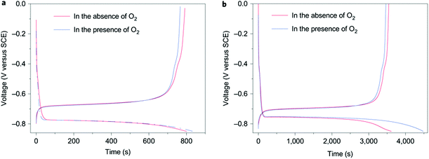 | ||
| Fig. 1 Typical charge/discharge curves of LiTi2(PO4)3 in aqueous 1.0 mol L−1 Li2SO4 electrolyte at (a) 4C and (b) 1C charge/discharge rates in the presence and absence of O2.22 (Reproduced with permission from Nature Publishing Group. Copyright 2010.) | ||
Based on this understanding, the LiTi2(PO4)3/Li2SO4/LiFePO4 aqueous batteries were fabricated by eliminating oxygen, adjusting the pH values of the electrolyte, and using carbon-coated electrode materials. The capacity of such aqueous Li-ion batteries remained over 90% after 1000 cycles when the batteries were fully charged/discharged in 10 min, and 85% after 50 cycles even when fully charged/discharged at a very low current for 8 h. Another work on assembling aqueous Li-ion batteries by using graphite coated with gel polymer electrolyte (GPE) and LISICON as the negatrode and LiFePO4 as the positrode in aqueous solution was published recently.23 A LISICON film consisting of Li2O–Al2O3–SiO2–P2O5–TiO2–GeO2 was simply put on the GPE to be a solid separator to keep water away and allow the passage of only Li+ ions. The mechanism of this type of aqueous Li-ion battery is illustrated in Fig. 2. When the cell is charging, Li+ ions will deintercalate from the LiFePO4 olivine structure, and then pass through the aqueous solution, LISICON film, and then GPE in sequence. The Li+ ions will finally intercalate in the graphite during the charging process. The reverse process will take place during discharging. The average discharging voltage of this LISICON film based aqueous Li-ion battery is up to 3.1 V, which leads to a specific energy value of 258 W h kg−1. The average discharging voltage of aqueous Li-ion batteries with the LISICON film coated Li metal negatrode and a LiMn2O4 positrode can be up to 4.0 V, which leads to a specific energy value of 446 W h kg−1.24 The Mg metal was also considered to replace the Li metal in similar aqueous batteries. The Grignard reagent of PhMgBr was used to stabilise the Mg metal negatrode, whilst the positrode was still made of LiFePO4 to construct a novel Mg metal and Li-ion hybrid rechargeable aqueous battery.25 The specific energy value of this interesting hybrid reached 245 W h kg−1. Similar to the aforementioned LiTi2(PO4)3/Li2SO4/LiFePO4 aqueous batteries, the aqueous Li2SO4 solution was also used as the electrolyte in these LISICON film based Mg metal and Li-ion hybrid aqueous batteries. In addition to its high ionic conductivity, the Li2SO4 aqueous electrolyte does not change the nature of LISICON as a solid-state electrolyte.
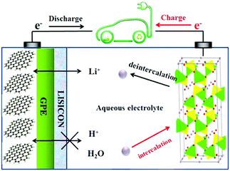 | ||
| Fig. 2 Schematic illustration of an aqueous Li-ion battery using the graphite coated by GPE (gel polymer electrolyte) and LISICON as the negatrode and LiFePO4 as the positrode in 0.5 mol L−1 Li2SO4 aqueous electrolyte.23 | ||
Although rarely reported in the literature, aqueous Na-ion batteries are also being developed to fulfil the demand of EES devices with low cost, high safety, and abundant resource. Similar to the investigation of aqueous Li-ion batteries, most work on aqueous Na-ion batteries has been focused on the electrode materials. A recent study revealed that hollow K0.27MnO2 nanospheres can facilitate the electron/ion transport kinetics in the negatrode, leading to long cyclability and high rate capability.26 A coin cell consisting of the hollow K0.27MnO2 nanosphere negatrode and NaTi2(PO4)3 positrode with 1.0 mol L−1 Na2SO4 aqueous electrolyte could exhibit a specific capacity of 84.9 mA h g−1 at 150 mA g−1, and a capacity of 56.6 mA h g−1 could be still maintained when the current was increased to 600 mA g−1. The capacity retention of the full cell was 83% at 200 mA g−1 after 100 cycles. It is obvious that more attention should be paid to investigation of the electrolytes of aqueous Na-ion batteries.
2.2. Aqueous Zn-ion batteries
The potential of Zn2+/Zn is negative enough to make Zn a preferred negatrode material, particularly in various aqueous batteries. In some aspects, Zn-ion rechargeable batteries can also be competitive with Li-ion batteries. For example, Zn is more abundant in the earth's crust, and has a higher theoretical volumetric charge capacity (5854 mA h mL−1-Zn vs. 2062 mA h mL−1-Li). Also, aqueous Zn-ion batteries are intrinsically safer due to their incombustible electrolytes. However, Zn dendrite formation and the increased irreversibility of the Zn/Zn2+ redox couple during the charge/discharge processes decrease critically the cycle life of Zn-ion batteries and worsen their discharge performance.A recent study revealed that a Zn//Co3O4 battery can overcome the drawbacks of conventional Zn rechargeable batteries mentioned above by electrodeposition of Zn on carbon fibres (CFs) with the Zn@CF shell–core structure to achieve dendrite-free cycling behaviour and a flexible negatrode. Similarly, electrodeposition of ultrathin porous Co3O4 nanosheets on Ni foam achieved a highly conductive and flexible positrode in the electrolyte of 1.0 mol L−1 KOH and 0.01 mol L−1 Zn(Ac)2 (Ac = acetate).27 The battery presented excellent cycling performance with a capacity retention of 80% after 2000 full cycles as shown in Fig. 3a. Fig. 3b demonstrates the assembling of a flexible Zn//Co3O4 battery, which powered a red LED. Other Zn battery designs were also reported, such as the Prussian blue/Zn rechargeable battery with a mixture of bio-ionic liquid and water as the electrolyte, and the Zn-ion battery based on NASICON structured Na3V2(PO4)3.28,29 The aqueous electrolyte compositions in these two reports were different, while both of the reported Zn batteries had an effective cycle life of more than 100 cycles. In both cases, the electrolytes affected the performance of the Zn-ion batteries.
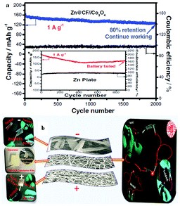 | ||
| Fig. 3 (a) Cycling performance of the Zn//Co3O4 battery at 1 A g−1 assembled with the Zn@CF and Zn plate (inset); (b) structure of a flexible Zn//Co3O4 battery and optical photographs of a flexible battery working at different states.27 (Reprinted with permission, copyright 2016, John Wiley & Sons, Inc.) | ||
2.3. Redox flow batteries
In a redox flow battery (RFB), redox couples that are soluble in the electrolyte are used to store and release energy when the battery is charging and discharging. In most cases, the redox couple or the electrolyte determines the specifications of the RFB. It is worth highlighting that all known commercial RFBs are based on aqueous electrolytes. In a previous review,28 specifications and operation performances of the most developed and commercially available RFBs are compared. The so called all-vanadium RFB has the highest efficiency and the longest cycle life, while the zinc–cerium and bromide–polysulfide RFBs have advantages in power density and cost, respectively. Here, we are not going to provide a comprehensive review of RFBs, but pick up some recent developments in large-scale devices and scientific frontiers. Some large scale RFBs (>10 kW) have been reported in the literature.28,29 Such a large output of the device is due to the stacked RFB cells. In the all-vanadium case, a 1 kW class RFB stack consisted of 14 cells, and a 10 kW class RFB stack consisted of eight 1 kW class stack modules with a configuration of 4 × 2 (serial × parallel).29 A recent report demonstrated an integration of dual-silicon photoelectrochemical cell into an RFB for unassisted photocharging by using the redox couples of Br3−/Br− and AQDS/AQDSH2 (cf.Fig. 4).30 The authors named this device solar rechargeable flow cell (SRFC). Fig. 4 illustrates the SRFC configuration. In the SRFC, the photoelectrochemical cell and RFB are connected through electrolyte circuit loops. First, AQDS is reduced to AQDSH2 on the photocathode and Br− is oxidised to Br3− on the photoanode simultaneously in the photoelectrochemical cell by short-circuiting the two photoelectrodes under illumination. The photoelectrochemical products AQDSH2 and Br3− are then stored in two individual reservoirs that can be used by the RFB in the SRFC. A commercial Nafion membrane was used as the separator in each cell. The SRFC could be self-photocharged to 0.8 V under simulated AM 1.5-G illumination and delivered a discharge capacity of up to 730 mA h L−1 after photocharging for 2 h.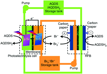 | ||
| Fig. 4 Schematic representation of the configuration of the solar rechargeable flow cell (SRFC). AQDS: 9,10-anthraquinone-2,7-disulphonic sodium; AQDSH2: 1,8-dihydroxy-9,10-anthraquinone-2,7-disulphonic sodium.30 | ||
2.4. Aqueous supercapacitors and supercapatteries
Similar to the aforementioned batteries, the standard electrolytes used in supercapacitors or supercapatteries (supercapattery is a hybrid of supercapacitor and battery) can be either aqueous or organic. In all variants, the device contains one or occasionally multiple species of supporting electrolytes that are not electroactive within the working voltage range, which is essential for electrolyte stability.Aqueous electrolytes, compared to their organic counterparts, are advantageous in terms of affordability, conductivity, heat capacity and environmental impact. The solutes of the aqueous electrolytes in either a supercapattery or supercapacitor can be any salt, acid, base, or their combination, but must be carefully selected to be harmonious with electrode materials. For example, a HCl solution is suitable for the CNT/PAn composite as the positrode,31–33 but a KCl solution is preferred for the CNT/PPy composite.32,34–37 The pH of an aqueous electrolyte can be greatly deterministic of the performance of electrode materials. A good example of this effect is the capacitive behaviour of MnO2 under non-stoichiometric conditions. Although MnO2 is one of the most widely used positrode materials for supercapacitors, it only exhibits a relatively rectangular cyclic voltammogram (CV) in neutral aqueous electrolytes, but presents a bell shaped CV (battery like behaviour) in alkaline solutions. The cause for these apparent dynamic responses is that within the MnO2 positrode the redox transition between MnO2 and MnOOH contributes to the observed pseudocapacitance which is featured by the rectangular CV. In neutral aqueous electrolytes, MnO2 is in the semiconductor state, leading to the relatively rectangular CV. However, MnO2 is reduced to Mn(OH)2 which is a poor conductor in alkaline solutions.38 Formation of the insulating Mn(OH)2 occurs because the solubility of MnOOH becomes significant in concentrated alkaline solutions.39,40 The dissolved Mn(III) species in turn undergo a reduction process to form Mn(II) species at low voltages and eventually into insoluble Mn(OH)2 by combining with OH− ions.38 In this case, the neutral aqueous electrolytes, such as Li2SO4, Na2SO4, K2SO4, and KCl solutions, are widely used in the MnO2 based supercapacitor and electrode materials studies.41–44 It has been found that the supercapacitor using a K2SO4 electrolyte can exhibit a specific energy value of 17.6 W h kg−1 at a specific power of 2 kW kg−1, which is higher than that of a similarly designed supercapacitor using a Li2SO4 electrolyte.43 As to the cycling performance, it was recently reported that an asymmetrical supercapacitor consisting of α-MnO2/CNT as positrode and activated carbon as negatrode with Na2SO4 aqueous electrolyte can retain 77% of its initial capacity after 20![[thin space (1/6-em)]](https://www.rsc.org/images/entities/char_2009.gif) 000 charge–discharge cycles at 50 A g−1.42
000 charge–discharge cycles at 50 A g−1.42
Another factor affecting the performance of supercapacitors and supercapatteries is the size of the hydrated ionic sphere (anion and cation). Regardless of what solutes are in the aqueous electrolytes, the real charge carriers are the hydrated ions, instead of the ions themselves. It is generally accepted that the ions of smaller spheres enhance the diffusion and intercalation rates due to their better kinetic movements.45,46 Furthermore, smaller spheres are able to travel deeper into the pores and hence access more active sites in the electrode material than larger spheres. This understanding is particularly important when considering the contribution of double layer capacitance. The Li+ ion is a typical example. Its salt is widely used in organic electrolytes because it is the smallest alkali metal ion. However, potassium and sodium salts (whose cations are larger than the Li+ ion) are often more commonly utilised in aqueous electrolytes because the hydrated K+ and Na+ spheres are much smaller than the hydrated Li+ sphere. Water also has a relatively narrow thermal window, which affects the application of aqueous electrolytes at low or sub-zero temperatures. However, many wind farms which require high speed energy storage are built in places where winds are more frequent and stronger in cold winter. A recent study on using the organoaqueous solutions of chloride salts, e.g. CaCl2 and KCl, has revealed promising results, decreasing the working temperature of CNTs and carbon electrodes to below −60 °C.47 This achievement may be explained by the unique affinity between Ca2+ ions and the oxy-groups on the surfaces of carbon nanotubes or activated carbon.
3. Organic electrolytes
3.1. Supercapacitors
Supercapacitors can offer high specific power (>10 kW kg−1) and long cycle life (>500![[thin space (1/6-em)]](https://www.rsc.org/images/entities/char_2009.gif) 000 cycles), and have been considered recently as a promising device in advanced and highly efficient energy storage management.48–50 Of different supercapacitors, electrical double-layer capacitors (EDLCs) are currently dominating the supercapacitor markets. The EDLC stores energy through the electrostatic interaction between electrodes and electrolyte ions. Thus, selection of the correct electrolyte matching with the electrode materials is the key for a successful EDLC.
000 cycles), and have been considered recently as a promising device in advanced and highly efficient energy storage management.48–50 Of different supercapacitors, electrical double-layer capacitors (EDLCs) are currently dominating the supercapacitor markets. The EDLC stores energy through the electrostatic interaction between electrodes and electrolyte ions. Thus, selection of the correct electrolyte matching with the electrode materials is the key for a successful EDLC.
Electrolytes used in supercapacitors must have high ionic conductivity and a wide electrochemical window, which impact the power capability and energy capacity, respectively. Compared to aqueous electrolytes, organic electrolytes composed of a salt and organic solvents provide a wider electrochemical window (>2.8 V), which enables higher specific energy.51–53 Based on the operating voltage, in this section, the authors will describe mainly the recent progress in the research and development of organic electrolytes used in some high voltage EDLCs and a special type of supercapattery, the so called Li-ion capacitors.52
Typical organic electrolytes such as tetraethylammonium tetrafluoroborate (TEABF4) dissolved in acetonitrile (AN) or propylene carbonate (PC) are widely used in commercial EDLCs and research, and generally operate up to 2.8 V. EDLCs using AN-based electrolytes demonstrate higher power and better low temperature performance compared to those using PC-based electrolytes.54–56 In 2010, NASA Tech Briefs reported an organic electrolyte with freezing temperatures as low as −85.7 °C. It was formulated by the addition of TEABF4 to mixed AN and 1,3-dioxolane (DOL) at 1![[thin space (1/6-em)]](https://www.rsc.org/images/entities/char_2009.gif) :
:![[thin space (1/6-em)]](https://www.rsc.org/images/entities/char_2009.gif) 1 by volume ratio. The cells filled with this electrolyte showed highly linear discharge curves over a wide range of temperatures.57 However, AN has not been used in Japan for many years due to its toxicity and low flash point. Thus, PC is usually considered to be a promising alternative solvent for commercial EDLCs. Without the toxicity of AN, PC is more preferred because of its wide electrochemical window, high electrolytic conductivity, wide liquid temperature range and resistance against hydrolysis.58,59
1 by volume ratio. The cells filled with this electrolyte showed highly linear discharge curves over a wide range of temperatures.57 However, AN has not been used in Japan for many years due to its toxicity and low flash point. Thus, PC is usually considered to be a promising alternative solvent for commercial EDLCs. Without the toxicity of AN, PC is more preferred because of its wide electrochemical window, high electrolytic conductivity, wide liquid temperature range and resistance against hydrolysis.58,59
It is also noteworthy to mention that the properties of the salt in the electrolyte may play a crucial role in the development of high performance EDLCs. Many research efforts have been focused on the selection and synthesis of supporting salts. It was reported that among various known salts, Et4NBF4 due to its wide electrochemical window, high solubility and ion conductivity in most solvents was the most common supporting salt for the organic electrolyte of EDLCs.59–61 However, in many common organic solvents, TEABF4 can only dissolve up to 1.0 mol L−1 which is not sufficient for the desired high conductivity. Some asymmetric tetraalkylammonium salts and cyclic quaternary ammonium salts were thus explored, including triethylmethylammonium (TEMABF4), 1-ethyl-1-methyl-pyrrolidinium (MEPYBF4), and tetramethylenepyrrolidinium (TMPYBF4). These salts have higher concentrations and hence offer high conductivities.62–66 Indeed, TEMABF4 showed higher solubility in PC, and may be used as an alternative to TEABF4.
Since energy capacity of a supercapacitor is the product of capacitance and squared voltage, the most effective strategy to increase both the energy and power densities of EDLCs is to raise the operating voltage.67 Many studies have shown that it is highly challenging to increase the operating voltage beyond 3 V for EDLCs using any known commercial electrolyte. In fact, the choices of supporting salts, solvents, and impurities of the electrolytes have a profound influence on the electrochemical window of the organic electrolyte.59,68 Also, research has identified that the ionic size and type of different salts have a great influence on the capacitance and power performance of EDLCs.69–71 It was observed that quaternary ammonium salts with small cations could achieve a high EDLC specific capacitance.69 Furthermore, the salt also plays an important role in affecting the electrochemical window of organic electrolytes.63,72,73 The ionic liquid N-butyl-N-methylpyrrolidinium bis(trifluoromethanesulfonyl)imide (PYR14TFSI) was used to formulate the electrolyte, and EDLCs containing PYR14TFSI in PC exhibited a high operating voltage (up to 3.5 V) and excellent cycling stability. A small capacitance loss of only 5% was achieved after 100![[thin space (1/6-em)]](https://www.rsc.org/images/entities/char_2009.gif) 000 cycles carried out at 3.5 V.74,75 Additionally, the spiro-(1,1′)-bipyrolidinium tetrafluoroborate (SBP-BF4) salt was also tested, confirming that the novel SBP-BF4/PC electrolyte in activated carbon based EDLCs had a high withstand voltage of up to 3.2 V and showed good capacitor behaviour. Unfortunately, these new organic salts are expensive compared to TEABF4, which inhibits their practical application.76 For the normal EDLCs with AN- or PC-based electrolytes, a voltage over 2.7 V may cause serious decomposition of the electrolyte and impurities (e.g. water) and irreversible reactions at the activated carbon electrode. Such unwanted reactions can result in gas evolution and passive film formation on the electrode surface.77–80 In the case of PC-based electrolytes, the gas evolution has been experimentally analysed using an H-type cell as illustrated in Fig. 5, which is capable of separately collecting gases from the positive and negative compartments.81 The analysis revealed CO2 and CO from the positrode, while H2 and other gases, like propylene, CO2, ethylene and CO, were found on the negatrode after a float-test applied at cell voltages above 3.0 V.81,82
000 cycles carried out at 3.5 V.74,75 Additionally, the spiro-(1,1′)-bipyrolidinium tetrafluoroborate (SBP-BF4) salt was also tested, confirming that the novel SBP-BF4/PC electrolyte in activated carbon based EDLCs had a high withstand voltage of up to 3.2 V and showed good capacitor behaviour. Unfortunately, these new organic salts are expensive compared to TEABF4, which inhibits their practical application.76 For the normal EDLCs with AN- or PC-based electrolytes, a voltage over 2.7 V may cause serious decomposition of the electrolyte and impurities (e.g. water) and irreversible reactions at the activated carbon electrode. Such unwanted reactions can result in gas evolution and passive film formation on the electrode surface.77–80 In the case of PC-based electrolytes, the gas evolution has been experimentally analysed using an H-type cell as illustrated in Fig. 5, which is capable of separately collecting gases from the positive and negative compartments.81 The analysis revealed CO2 and CO from the positrode, while H2 and other gases, like propylene, CO2, ethylene and CO, were found on the negatrode after a float-test applied at cell voltages above 3.0 V.81,82
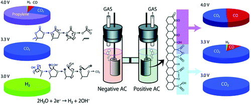 | ||
| Fig. 5 Illustration of gas evolution from an EDLC cell upon application of different voltages.78 (Reproduced with permission from The Royal Society of Chemistry. Copyright 2012.) | ||
Many efforts have been focused on the implementation of novel solvents with wider operating voltage ranges. In 2011, new electrolytes based on linear sulfones were reported, showing that ethyl isopropyl sulfone (EiPS)-based electrolytes have a high voltage durability of 3.7 V with high cycling stability.83 Also, it was reported that alkylated cyclic carbonates had a withstand voltage higher than 3.0 V.84 Particularly, the 2,3-butylene carbonate (2,3-BC) electrolyte could withstand up to 3.5 V mainly because of the outstanding oxidation resistance of 2,3-BC.
On the other hand, fluorinated solvents possess remarkably higher chemical and electrochemical stability owing to the high electronegativity and low polarizability of the fluorine atom.85 For example, a fluorinated solvent, fluoroacetonitrile (FAN), was investigated to offer a wide electrochemical window. However, the findings also showed that the 1.0 mol L−1 TEABF4/FAN electrolyte had a lower ionic conductivity compared to the 1.0 mol L−1 TEABF4/AN solution.86 Similarly, in an effort to address the low flash point and relatively low electrochemical stability of AN-based electrolytes, adiponitrile (ADN) was studied as a possible solvent for EDLCs.87 It was found that EDLCs using 0.7 mol L−1 TEABF4/ADN as the electrolyte showed a higher operating voltage of 3.75 V, and a high capacitance retention over 35![[thin space (1/6-em)]](https://www.rsc.org/images/entities/char_2009.gif) 000 cycles carried out at a cell voltage as high as 3.5 V. However, the ionic conductivity of this new electrolyte needs further improvement because it is much lower than that of AN-based electrolytes. Although these novel electrolytes have significantly increased operating voltages, their relatively high viscosity and low ionic conductivity, especially at room temperature, reduce the power performance of such EDLCs.
000 cycles carried out at a cell voltage as high as 3.5 V. However, the ionic conductivity of this new electrolyte needs further improvement because it is much lower than that of AN-based electrolytes. Although these novel electrolytes have significantly increased operating voltages, their relatively high viscosity and low ionic conductivity, especially at room temperature, reduce the power performance of such EDLCs.
To further increase the working voltage, extensive efforts have been devoted to the development of the so called Li-ion capacitor (LIC). Typically, an LIC combines a Li-ion battery electrode and an EDLC electrode, and is hence, in principle, a supercapattery. It usually displays a high working voltage of ∼4.0 V, leading to higher energy capacity (>30 W h kg−1). Because of the smaller size of the solvated Li+ ion in organic solvents than in water, organic electrolytes composed of LiClO4 or LiPF6 and mixtures of two or more carbonate solvents (e.g., EC + DMC) have been widely used in LICs. In a few previous studies on degradation mechanisms, it was found that 4.3 and 1.5 V versus Li+/Li were the critical potentials for the positrode and negatrode of EDLCs, respectively.88 Coupled with an activated carbon (AC) negatrode, many battery positrode materials such as LiMn2O4, LiFePO4 and LiCoO2 were investigated.89–91 An example cell of AC/1.0 mol L−1 LiClO4–AN/LiMn2O4 showed a specific energy of 45 W h kg−1 at a power output of 0.03 kW kg−1.90,92
Using a 1.0 mol L−1 LiPF6/EC + DMC electrolyte, a 5.0 V positrode, LiNi0.5Mn1.5O4 (LMNO), was demonstrated in similar configurations.93,94 These cells display a sloping voltage profile from 1.0 to 3.0 V, a high specific energy of 56 W h kg−1, and an excellent capacity retention of 95% after up to 1000 cycles.
A later investigation used the same electrode combinations and electrolyte, but a higher cell voltage of 3.3 V. Some of the findings are presented in Fig. 6. A promising capacity retention of 89% was observed even after 4000 cycles with an average specific energy and power of about 50 W h kg−1 and 1100 W kg−1.95 Unfortunately, the capacity fading of this cell became more pronounced with increasing cell voltage. For example, the cells at 3.4 V and 3.5 V showed capacity retention of only 58% and 23% after 4000 and 2000 cycles, respectively. This phenomenon may be ascribed to the constant shifting of the LNMO plateaus to higher potentials as a result of Li loss upon surface layer formation which in turn leads to degradation of the electrolyte. Remarkably, in a 2006 report,96 in another study, AC and graphite were used as the negatrode and positrode materials to fabricate a simple capacitor containing the electrolyte of 1.5 mol L−1 TEMABF4/PC or 1.5 mol L−1 TEMAPF6/PC. This AC/graphite capacitor was tested to show that the electrolyte composition and the weight ratio of AC to graphite had a profound influence on the performance of the capacitor. Further investigations confirmed the effect of other factors,97–103 including the type of salts,98,99 solvents,100–102 and weight ratios of AC/graphite,103 on the performance of this asymmetric AC/graphite capacitor. Specially, it was noticed that EC had an extraordinarily retardant tendency towards anions (e.g. PF6−, ClO4−, DFOB− and BF4−) intercalating into the interlayer space of graphite. This behaviour was attributed to the strong solvation of some anions by EC (see Fig. 7).100–102 It should be mentioned that the investigated LICs with an AC negatrode had a medium operating voltage in the range of 2.5–3.5 V, and their energy capacity was rather limited.
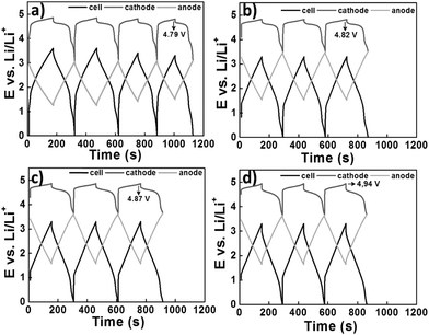 | ||
| Fig. 6 Charge–discharge profiles of the LNMO/AC LIC with a cell voltage of 3.3 V at the (a) beginning, (b) after 1000 cycles, (c) 2000 cycles and (d) 3000 cycles. It can be seen that the potential of the LNMO plateau is relatively low (4.79 V) at the beginning, but gradually increases to higher potentials (4.82 → 4.87 → 4.94 V) during cycling which leads to an increase in the capacity.95 (Reprinted with permission from The Electrochemical Society, Copyright 2014.) | ||
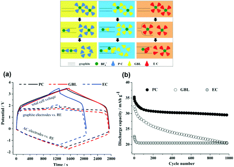 | ||
| Fig. 7 (a) Potential profiles of graphite positrode and AC negatrode vs. AC quasi-reference electrode in the AC/graphite capacitors using the electrolytes of 1.5 mol L−1 SBPBF4–PC, –GBL and –EC, respectively, during the 1st galvanostatic charge–discharge. (b) Cycling performance of AC/graphite capacitors using different electrolyte solutions.102 (Reprinted with permission from Elsevier. Copyright 2015.) | ||
LICs employing a combination of AC positrode and Li-ion battery negatrode were also studied, revealing working voltages higher than 4.0 V. Fig. 8 illustrates a case with a Li+ intercalation graphite negatrode. As a result, these LICs could offer higher energy densities and long cycle life.104–108 Battery negatrode materials such as carbon-based materials (mostly graphite) and Li4Ti5O12 were proposed and investigated. Typical compositions of the reported electrolytes used in LICs were based on solutions of LiPF6 or LiClO4 dissolved in mixtures of two or more solvents. These electrolytes are also mainly used in Li-ion batteries (LIBs).106,107,109 An LIC cell of hard carbon (HC)/1.3 mol L−1 LiPF6/EC–DEC–PC/AC was reported to show a high specific energy of 82 W h kg−1 at 2.4C. Another LIC cell with 1.0 mol L−1 LiPF6 in EC + DMC (1![[thin space (1/6-em)]](https://www.rsc.org/images/entities/char_2009.gif) :
:![[thin space (1/6-em)]](https://www.rsc.org/images/entities/char_2009.gif) 1, v/v) exhibited the highest specific energy of 103.8 W h kg−1 and a good capacity retention of over 85% after 10
1, v/v) exhibited the highest specific energy of 103.8 W h kg−1 and a good capacity retention of over 85% after 10![[thin space (1/6-em)]](https://www.rsc.org/images/entities/char_2009.gif) 000 cycles in the voltage range from 1.5 V up to 4.5 V.110 Since the graphite negatrode did not initially contain Li, pre-lithiation of the graphite negatrode was a key aspect of this LIC.111 It was also reported that capacity loss of the LICs during charge–discharge cycling was obviously reduced by addition of Li metal into the cell.112,113
000 cycles in the voltage range from 1.5 V up to 4.5 V.110 Since the graphite negatrode did not initially contain Li, pre-lithiation of the graphite negatrode was a key aspect of this LIC.111 It was also reported that capacity loss of the LICs during charge–discharge cycling was obviously reduced by addition of Li metal into the cell.112,113
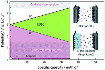 | ||
| Fig. 8 Typical electrode potential profiles for an EDLC cell and an LIC cell composed of an AC positrode and a graphite negatrode.78 (Reproduced with permission from The Royal Society of Chemistry. Copyright 2012.) | ||
The highest potential of the AC electrode should be lower than 4.5 V vs. Li+/Li, while the lowest potential of the HC/stabilized Li metal powder (SLMP) electrode should be greater than 0.1 V vs. Li+/Li. Moreover, the capacitance degradation of this LIC was less than 1% after 1300 cycles in the voltage range of 2.0 to 4.1 V.114
Additionally, it was proposed to use quaternary alkyl ammonium and PC based organic electrolytes in LICs. The result showed that the sizes of quaternary alkyl ammonium cations played a very important role in the performance of LICs.115 Nonetheless, based on Li-salt electrolytes, the shortcomings of LICs were found to be a poor performance at low temperatures116 and a low rate capability resulting from the low ionic conductivity and the battery-type graphite negatrode. Therefore, more studies should be focused on the development of new LIC electrolytes to overcome the above-mentioned drawbacks in the future. It is generally known that a number of electrolyte additives can be used in Li-ion batteries and also supercapacitors as discussed below.
There are a few reports on improving the properties of the supercapacitors with the help of functional additives.117–123 For example, the electrochemical characteristics of EDLCs consisting of electrodes of microporous titanium carbide derived carbon (TiC-CDC) were studied in 1.0 mol L−1 (C2H5)3CH3NBF4/PC solutions with several additives, such as diethyl sulfite (DES) and 1,3-propylene sulfite (PS).117–120 These additives are actually well-known for LIBs. The results showed that DES and PS additives could obviously change both the viscosity and conductivity of PC-based electrolytes, affecting the capacitance and the characteristic time constant, and the power and energy values of the obtained EDLCs (see Fig. 9). Regarding EDLCs, upon addition of Li2O2 into the 1.5 mol L−1 TEABF4/AN electrolyte, the electrochemical window was increased to over 4.0 V. The EDLC adopting this electrolyte could obtain higher specific capacitance at high scan rates of 10–500 mV s−1.121
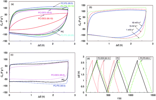 | ||
Fig. 9 Cyclic voltammograms expressed as specific capacitance vs. cell voltage for EDLCs with different solvents and addition of 1.0 mol L−1 (C2H5)3CH3NBF4 at 10 mV s−1 and −20 °C (a), at different voltage scan rates with mixed PC![[thin space (1/6-em)]](https://www.rsc.org/images/entities/char_2009.gif) : :![[thin space (1/6-em)]](https://www.rsc.org/images/entities/char_2009.gif) PS (95 PS (95![[thin space (1/6-em)]](https://www.rsc.org/images/entities/char_2009.gif) : :![[thin space (1/6-em)]](https://www.rsc.org/images/entities/char_2009.gif) 5) (b), and at 1 mV s−1 and 0 °C (c). Galvanostatic charging–discharging cycles (ΔE = 3.0 V, j = 10 mA cm−2) for electrolytes with different solvents (d).117 (Reprinted with permission from The Electrochemical Society. Copyright 2014.) 5) (b), and at 1 mV s−1 and 0 °C (c). Galvanostatic charging–discharging cycles (ΔE = 3.0 V, j = 10 mA cm−2) for electrolytes with different solvents (d).117 (Reprinted with permission from The Electrochemical Society. Copyright 2014.) | ||
Another electrolyte additive, 1,3,5-trifluorobenzene (TFB), was found to be able to improve the mobility of BF4− ions near the microporous electrode, and enhance the high rate performance of the AC/Li high voltage capacitors.122In situ formation of fluorophosphate additives in the commercial 1.0 mol L−1 LiPF6/EC + DMC electrolyte was tested in LICs to create a stable layer of solid electrolyte interphase (SEI) on the electrode surface and broaden the operating voltage window to 4.8–1.2 V.123 This finding indicates a new strategy for designing proper electrolyte additives to further widen the electrochemical window of existing electrolytes and enhance the performances of the supercapacitors.
3.2. Lithium ion batteries
Among all rechargeable batteries, LIBs are the most popular EES devices because they have high energy density, acceptable cycle life, no memory effect, and low self-discharging.124–126 As mentioned above, an electrolyte functions to conduct ions but insulate electrons, and can be in various forms such as an ionic liquid, a molten salt, or a solid ionic conductor, but more often a salt dissolved in a solvent. Some EES devices, such as supercapacitors, can work with almost any liquid electrolyte, but LIBs would refuse to work properly if the electrolytes used were incorrect.127–129 In this section, we review the recent progress in organic electrolytes for currently prevailing LIBs, focusing on conventional electrolytes, high voltage electrolytes and highly concentrated electrolytes.Alkyl carbonates are considered to be the most suitable solvents for dissolution of lithium salts, because they have acceptable electrochemical stability, high ionic conductivity, wide operating temperature range and sufficiently low toxicity.127–129 It is well known that due to carbon atoms being at an oxidation state of +4, alkyl carbonates have high anodic and low cathodic stability. For example, the oxidation potential of EC-based electrolytes can reach up to 4.5 V vs. Li+/Li on a spinel positrode surface.130,131
Meanwhile, the EC-based electrolytes show excellent compatibility with graphite negatrodes because the reduction of EC on graphite electrodes can lead to the formation of a protective SEI film.132–136 Thus, EC is a critical component to obtain sufficient passivation of a graphite negatrode in standard electrolyte solutions for LIBs.137
Like EC as a mandatory component, the LiPF6 salt has also become an indispensable solute in almost all LIBs. LiPF6 is well known for its high solubility and conductivity, great anodic stability, and good capability of passivating Al current collectors at positive potentials.138 However, LiPF6 has a main disadvantage: it easily decomposes into LiF and PF5 at temperatures higher than 60 °C. The PF5 can then cause a series of irreversible reactions on both the positrode and negatrode, resulting in performance deterioration.139,140 LiN(SO2CF3)2 (LiTFSI) and LiC(SO2CF3)3 (LiTFSM) show good thermal and chemical stability compared to LiPF6.141–144 Unfortunately, they are highly corrosive to the Al positrode current collector. As shown in Fig. 10, corrosion of Al was typically observed at potentials above 4.25 V vs. Li+/Li.145 Therefore, the most common electrolyte solutions for LIBs are composed of 1.0 mol L−1 LiPF6 and binary mixtures of EC combined with a linear carbonate of low viscosity, e.g. dimethyl carbonate (DMC), ethyl methyl carbonate (EMC) or diethyl carbonate (DEC).
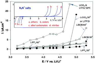 | ||
| Fig. 10 Anodic behaviour of Al foil (current collector for positrode) in various Li salt solutions (alkyl carbonates). The inset includes schematic representation of the potentio-dynamic behaviour of an inert Pt or glassy carbon electrode in various organic solutions containing tetra-alkyl ammonium salts, e.g. (C4H9)4NClO4. When the anodic stability is high, the cathodic stability is low and vice versa.129 (Reprinted with permission from The Electrochemical Society. Copyright 2015.) | ||
Besides LiPF6 and carbonate solvents, various electrolyte additives have been proposed and tested to improve the battery performance and safety. The progress and prospects of functional additives for LIBs are reviewed recently, ranging from negatrode additives, positrode additives, safety additives, and salt type additives.146
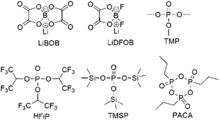
One of the most economical and easiest strategies to improve the stability of the positrode–electrolyte interface is using additives. The mechanism is that additives are preferably oxidised on the positrode surface to generate a stable interfacial layer, which inhibits the detrimental reaction of electrolytes at high positive potentials. Reported additives include (1) inorganic compounds such as lithium bis(oxalato)borate (LiBOB)152–158 and lithium difluoro(oxalato)borate (LiDFOB),159 (2) phosphite-derivatives such as trimethyl phosphite (TMP),160 tris(hexafluoro-iso-propyl)phosphate (HFiP),161,162 tris(trimethylsilyl)phosphite (TMSP),163–166 (ethoxy)pentafluorocyclotriphosphazene (PFPN),167 and 1-propylphosphonic acid cyclic anhydride (PACA),168 (3) sulfonate esters such as 1,3-propane sultone (PS),169 and 1,3-propanediol cyclic sulfate (PCS),170 and (4) some carboxyl anhydrides.169,171,172 These additives, some of which are shown with their molecular structures in Fig. 11, are all very effective in alleviating the decomposition of the electrolyte at the highly charged positrode.
Among these additives, LiBOB has been recognised as a highly promising multifunctional additive. The oxidation of LiBOB on the positrode could generate a thin surface film to inhibit further oxidation of the electrolyte.156 Meanwhile, the presence of LiBOB could also prevent the dissolution of Mn or Ni from the positrode surface, which might originate from the inhibition of formation of acidic species, e.g. HF or PF5.156 Additionally, a robust and stable SEI film on graphite produced by the reduction of LiBOB was observed.173,174 Compared to LiBOB, LIB cells with LiDFOB showed a greatly improved capacity retention of more than 92% after 100 cycles, which might be ascribed to the more stable SEI film with lower interfacial resistance on the negatrode surface.175 The LiDFOB-containing electrolyte was also found to work well with the high voltage positrode LiCoPO4, leading to higher reversible charge/discharge capacity and better cycling stability. XPS and FTIR-ATR analyses further confirmed that LiDFOB was helpful in the formation of a stable interphase film with borates, suppressing the decomposition of EC to form poly(ethylene carbonate) (PEC) (see Fig. 12).157
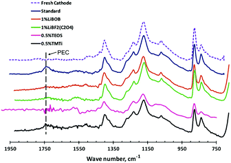 | ||
| Fig. 12 FTIR-ATR spectra of the Li1.17Mn0.58Ni0.25O2 positrode after charging–discharging cycling in different additive-containing electrolytes.157 (Reprinted with permission from Elsevier. Copyright 2011.) | ||
Recently, a series of novel lithium alkyl/aryl trimethyl borates were designed and prepared as positrode film forming additives.176 The cycling performance of graphite/LiNi0.5Mn1.5O4 cells with the electrolyte containing such additives is presented in Fig. 13. It can be seen that incorporation of lithium organoborate additives into 1.0 mol L−1 LiPF6 in EC/EMC results in improved capacity retention and efficiency of the graphite/LiNi0.5Mn1.5O4 cells. As confirmed by ex situ surface analyses via TEM, SEM, XPS and IR-ATR, the improvement was because incorporation of lithium 4-pyridyl trimethyl borate (LPTB) led to the generation of a borate rich passivation layer on the surface of both the positrode and negatrode. The mechanism is that the tetraalkyl borate is oxidised by the metal oxide surface to irreversibly generate a metal oxide borate complex, which in turn can inhibit electrolyte oxidation and Mn/Ni dissolution from the positrode, resulting in improved capacity retention and efficiency.
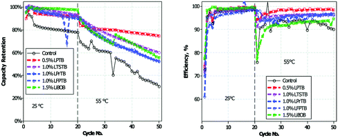 | ||
| Fig. 13 Cycling performance of graphite/LiNi0.5Mn1.5O4 cells at 25 and 55 °C in electrolytes with and without added lithium 4-pyridyl trimethyl borate (LPTB).176 (Reproduced with permission from The Royal Society of Chemistry. Copyright 2016.) | ||
Based on the above discussion, these additives generally tend to be electrochemically oxidised during charging of the cell to high voltages, and form a passivation layer on the positrode surface, and then suppress the reactivity of the charged electrode and electrolyte. The result has shown that the addition of these high voltage additives could enhance the cycling performance of the high voltage cells.
A recent study of the 5 V LiNi0.4Mn1.6O4 positrode with 40 different additives, such as fluoroethylene carbonate (FEC), PS and LiBOB, revealed that these additives could retard self-discharge. This improvement may be also related to oxidative electrolyte decomposition due to the high lithium (de-)insertion potentials. The study showed that among the 40 additives, only one compound, succinic anhydride (SA), helped to decrease capacity loss per cycle and enhance coulombic efficiency. Therefore, SA is a promising candidate as a high voltage additive to realise rechargeable LIB with high energy density.
On the other hand, it is a major challenge to develop novel stable solvents with intrinsic anodic ability for high voltage electrolytes that have good compatibility with electrodes. Many novel solvents with a high anodic potential have been reported, including dinitriles,177–182 sulfones,183–194 and fluorinated solvents.195–198 For example, in 1994, glutaronitrile (GLN) and adiponitrile (ADN) were reported to offer exceptionally high anodic stability at ∼8.3 V vs. Li+/Li.61,199,200
In general, dinitriles are known for their extra anodic stability on positrode surfaces, high dielectric constant and excellent thermal properties (high boiling point and flash point). However, they cannot be used alone in LIBs owing to their high melting point, high viscosity and poor wettability with the separator. Therefore, dinitriles can be used as a co-solvent with other solvents such as EC or EMC to improve the physical properties of dinitrile-based electrolytes. The 1.0 mol L−1 LiBF4/EC + DMC + sebaconitrile (25![[thin space (1/6-em)]](https://www.rsc.org/images/entities/char_2009.gif) :
:![[thin space (1/6-em)]](https://www.rsc.org/images/entities/char_2009.gif) 25
25![[thin space (1/6-em)]](https://www.rsc.org/images/entities/char_2009.gif) :
:![[thin space (1/6-em)]](https://www.rsc.org/images/entities/char_2009.gif) 50, by vol.) showed an excellent high oxidation stability above 6.6 V vs. Li+/Li on glassy carbon. On the Li2Ni0.98Co0.02PO4F positrode, this electrolyte was found to be stable at ca. 5.3 V vs. Li+/Li.177,178 It should be noticed that these dinitrile-based electrolytes are incompatible with graphite-based negatrodes, which results from the easy reduction of nitriles (C
50, by vol.) showed an excellent high oxidation stability above 6.6 V vs. Li+/Li on glassy carbon. On the Li2Ni0.98Co0.02PO4F positrode, this electrolyte was found to be stable at ca. 5.3 V vs. Li+/Li.177,178 It should be noticed that these dinitrile-based electrolytes are incompatible with graphite-based negatrodes, which results from the easy reduction of nitriles (C![[double bond, length as m-dash]](https://www.rsc.org/images/entities/char_e001.gif) N) on common negatrode materials such as Li metal or graphite, leading to deterioration of the cycling performance.
N) on common negatrode materials such as Li metal or graphite, leading to deterioration of the cycling performance.
To improve the compatibility of these electrolytes with the graphite negatrode, LiBOB,180,181 vinylene carbonate (VC) and FEC182 have been studied as additives. The findings showed evidence for the formation of a stable SEI on the graphitic negatrode that protected the dinitrile solvent from undergoing reductive decomposition. Fairly good capacity and cycling behaviour were observed upon addition of VC and FEC to the electrolyte of 1.0 mol L−1 LiTFSI and 0.25 mol L−1 LiBF4/ADN in the mesoporous carbon microbead (MCMB) half-cell and the MCMB/LiCoO2 full cell.182
Sulfones with high oxidation potentials have continued to attract attention as possible electrolyte solvents for LIBs. Electrolytes formed with ethylmethyl sulfone (EMSF) as the solvent exhibited an extraordinary anodic stability at ca. 5.8 V vs. Li+/Li, promising a wide range of possible high voltage applications.183 This finding agreed well with computed oxidation potentials for a series of sulfone-based molecules functionalised with fluorine, cyano, ester, and carbonate groups.201,202 In addition, it was found that sulfones with strong electron-withdrawing groups (such as –F and –CN) have higher oxidation potentials than the non-functionalised ones. An investigation of the electrochemical stability of five sulfone-based electrolytes by cyclic voltammetry found that among these solvents, tetramethylene sulfone (TMS) and EMSF showed the highest anodic stability on Pt working electrodes (see Fig. 14).203 The Li4Ti5O12/LiMn2O4 full cell with the 1.0 mol L−1 LiPF6/TMS + EMC blended electrolyte exhibited a fairly long cycle life of 1000 cycles at the 2C rate. However, their application in actual LIBs was limited by their inability to form a stable SEI layer on graphitic negatrodes. It has also been reported that the introduction of additives such as VC,186–188 LiBOB,189,190p-toluenesulfonylisocyanate (PTSI)191 and hexamethylenediisocyanate (HDI)192 can promote SEI film formation in sulfone-based electrolytes, giving a cycling performance equal to that of the conventional carbonate electrolytes. Molecular dynamic simulations suggested that in the 1.0 mol L−1 LiPF6/TMS + DMC electrolyte, TMS tended to preferentially adsorb on the positrode surface. Thus, the anodic stability of this mixture was dominated by sulfone instead of carbonate.194 This conclusion is consistent with experimentally observed increased oxidative stability of sulfone-based electrolytes. Based on the above mentioned results, although dinitriles and sulfones exhibit high anodic stability on various positrode surfaces and low flammability, they suffer from their intrinsic high viscosity, low conductivity and poor wettability toward the electrodes and separators, which cause poor rate performance of the battery. More importantly, they do not form a protective SEI film on the graphite negatrode, which severely hinders their application in commercial LIBs.
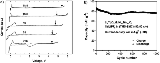 | ||
| Fig. 14 Sulfone-based electrolytes: (a) cyclic voltammograms of 1.0 mol L−1 LiTFSI in various neat sulfones on a Pt working electrode (Note: EMS in (a) is the same as EMSF in the main text.); and (b) cycling performance of a full lithium ion cell based on LiNi0.5Mn1.5O4/Li4Ti5O12 in 1.0 mol L−1 LiPF6/TMS + EMC.193 (Reprinted with permission from Elsevier. Copyright 2009.) | ||
At present, fluorinated electrolytes appear more appropriate for high voltage LIBs. Owing to the high electronegativity and low polarisability of the fluorine atom, fluorinated solvents possess increased oxidative or anodic stability.203,204 However, they also have poorer resistance against reduction. The first comparison of the high voltage cyclability between Li/LiCoO2 batteries containing FEC-based electrolytes and EC-based electrolytes concluded that the cell with the FEC-base electrolytes delivered a higher and more stable discharge capacity at a high cut-off voltage of 4.5 V.195 This conclusion also agreed with the results from later electrochemical evaluation of the Li/LiNi0.5Mn1.5O4, Li4Ti5O12/LiNi0.5Mn1.5O4 and Si/LiCoPO4 cells.196,197,205 These high voltage batteries demonstrated significantly improved capacity retention, which was attributed to the high anodic stability of the fluorinated electrolytes. However, because fluorinated solvents have less negative reduction potentials, they generally have poorer compatibility with graphite based negatrodes. To improve the stability of the graphite/F-electrolyte interface, a new solvent, 1,1,1,3,3,3-hexafluoroisopropyl methyl ether (HFPM), with a more negative reduction potential was prepared and used as the co-solvent to prepare a fluorinated electrolyte of 1.0 mol L−1 LiPF6/FEC + DMC + EMC + HFPM (2![[thin space (1/6-em)]](https://www.rsc.org/images/entities/char_2009.gif) :
:![[thin space (1/6-em)]](https://www.rsc.org/images/entities/char_2009.gif) 3
3![[thin space (1/6-em)]](https://www.rsc.org/images/entities/char_2009.gif) :
:![[thin space (1/6-em)]](https://www.rsc.org/images/entities/char_2009.gif) 1
1![[thin space (1/6-em)]](https://www.rsc.org/images/entities/char_2009.gif) :
:![[thin space (1/6-em)]](https://www.rsc.org/images/entities/char_2009.gif) 4, by vol.), leading to a remarkable anodic stability at 5.5 V vs. Li+/Li, and good compatibility with the graphite negatrode. Particularly, as shown in Fig. 15, high-voltage MCMB/LiNi0.5Mn1.5O4 18
4, by vol.), leading to a remarkable anodic stability at 5.5 V vs. Li+/Li, and good compatibility with the graphite negatrode. Particularly, as shown in Fig. 15, high-voltage MCMB/LiNi0.5Mn1.5O4 18![[thin space (1/6-em)]](https://www.rsc.org/images/entities/char_2009.gif) 650 cells containing this F-electrolyte exhibited a good capacity retention of 82% after 200 cycles, promising enhanced safety and longevity.198
650 cells containing this F-electrolyte exhibited a good capacity retention of 82% after 200 cycles, promising enhanced safety and longevity.198
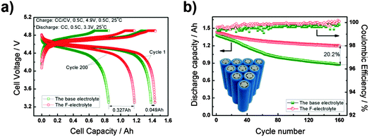 | ||
Fig. 15 (a) Voltage profiles for the charge–discharge cycles and (b) cycling performance according to the CC–CV protocol of the 18![[thin space (1/6-em)]](https://www.rsc.org/images/entities/char_2009.gif) 650 MCMB/LiNi0.5Mn1.5O4 battery in the voltage range of 3.3–4.9 V at the 0.5C rate.198 (Reproduced with permission from The Royal Society of Chemistry. Copyright 2015.) 650 MCMB/LiNi0.5Mn1.5O4 battery in the voltage range of 3.3–4.9 V at the 0.5C rate.198 (Reproduced with permission from The Royal Society of Chemistry. Copyright 2015.) | ||
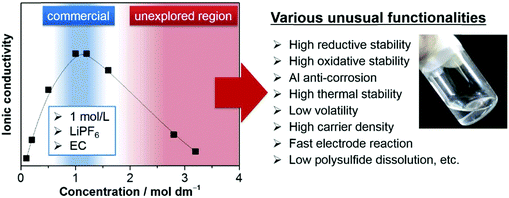 | ||
| Fig. 16 Typical ionic conductivity curve of the Li salt–aprotic solvent mixture. Highly concentrated electrolytes, having been outside the mainstream research due to decreased ionic conductivity, are recently receiving intensive attention because of various unusual functionalities beneficial to battery applications.206 | ||
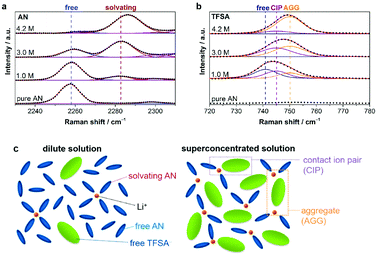 | ||
Fig. 17 Raman spectra of LiTFSA/AN solutions in the spectral range of (a) 2230–2310 cm−1 (C![[triple bond, length as m-dash]](https://www.rsc.org/images/entities/char_e002.gif) N stretching mode of AN molecules) and (b) 720–780 cm−1 (S–N stretching, C–S stretching, and CF3 bending mode of TFSA−). Points and solid lines denote experimental spectra and fitting curves, respectively. (c) Representative environment of Li+ in a conventional dilute solution (i.e., ∼1.0 mol dm−3) and a salt-superconcentrated solution (i.e., 4.2 mol dm−3).207 (Reprinted with permission from American Chemical Society. Copyright 2014.) N stretching mode of AN molecules) and (b) 720–780 cm−1 (S–N stretching, C–S stretching, and CF3 bending mode of TFSA−). Points and solid lines denote experimental spectra and fitting curves, respectively. (c) Representative environment of Li+ in a conventional dilute solution (i.e., ∼1.0 mol dm−3) and a salt-superconcentrated solution (i.e., 4.2 mol dm−3).207 (Reprinted with permission from American Chemical Society. Copyright 2014.) | ||
HCEs could affect other electrode processes in LIBs. For example, a PC solution of the LiBETI (that is LiN(SO2C2F5)2) salt could significantly improve the reversibility of Li metal deposition and stripping.208 After this path-breaking work, it was reported that stable Li metal deposition and stripping reactions in HCEs with ether solvents were observed.209–211 At high concentrations, the LiTFSI/DOL + DME electrolyte could not only effectively suppress dendrite formation at the metallic Li negatrode but also inhibit the dissolution of lithium polysulphide, resulting in excellent cycling performance and improved safety.209 In this case, for unknown reasons, a rather low columbic efficiency of ca. 71% during the Li plating/stripping processes was obtained. In contrast, a very high coulombic efficiency of up to 99.1% at 10 mA cm−2 for >6000 cycles in a Li/Li cell and an average efficiency of 98.4% at 4 mA cm−2 for >1000 cycles in a Li/Cu cell were reported in the 4.0 mol L−1 LiFSA/DME (lithium bis(fluorosulfonyl)imide/1,2-dimethoxyethane) electrolyte (see Fig. 18).210 The excellent high-rate cycling stability of the Li metal negatrode in the HCE of 4.0 mol L−1 LiFSI/DME was attributed to the selection of a reduction-stable solvent, a highly dissociated Li salt, and a high electrolyte concentration.
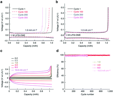 | ||
| Fig. 18 Electrochemical performance of Li metal plating/stripping on a Cu working electrode. (a) Voltage profiles for the cell cycled in 1.0 mol L−1 LiFSI–DME; (b) voltage profiles for the cell cycled in 4.0 mol L−1 LiFSI–DME; (c) polarization of the plating/stripping for the 4.0 mol L−1 LiFSI–DME electrolyte with different current densities. (d) CE of Li deposition/stripping in 4.0 mol L−1 LiFSI–DME at different current densities.210 | ||
It is widely known that the graphite negatrode prefers to working in EC-based electrolytes. This is primarily because only EC-based electrolytes allow for highly reversible Li+ intercalation into graphite. Other popular solvents such as PC, DME, acetonitrile (AN) and dimethyl sulfoxide (DMSO) easily destroy the graphite crystalline structure by the co-intercalation of solvent molecules and Li+ ions into graphite.212–215
Recently, several reports confirmed that HCEs containing these popular solvents showed enhanced reductive stability, suppressing the co-intercalation of solvent molecules to allow reversible lithium intercalation into the interlayers of graphite.207,216–219 The unusual reductive stability of a super-concentrated LiTFSA/AN electrolyte (4.2 mol L−1) was investigated, revealing the origin by first-principles calculations combined with spectroscopic analyses.207,220 As shown in Fig. 19, the obtained reversible capacity of the cell using the 4.2 mol L−1 LiTFSA/AN electrolyte was ca. 330 mA h g−1, which was close to the theoretical capacity (372 mA h g−1) based on fully lithiated carbon, LiC6. This is indication of a reversible operation of the graphite negatrode in an AN-based electrolyte. The enhanced reductive stability can be linked to the excellent and compact SEI film with high ionic conductivity, which was due to the reductive decomposition of the TFSA− anion, instead of the AN solvent. The DFT-MD simulation results confirmed that the sacrificial anion reduction hindered electron reductive decomposition of AN, leading to improved electrochemical stability (see Fig. 20).220 Interestingly, it was also found that Li+ intercalation into graphite in HCEs could be ultrafast with either LiTFSI or LiFSI and AN or DME, even exceeding that in currently used commercial EC-based electrolytes, for example, 1.0 mol L−1 LiPF6–EC/DMC.207,218
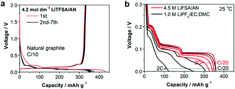 | ||
Fig. 19 (a) Charge–discharge curves of a natural graphite/Li metal cell with 4.2 mol L−1 LiTFSA/AN electrolyte at C/10 rate. (b) Lithium intercalation voltage curves of a natural graphite/lithium metal half-cell with superconcentrated 4.5 mol L−1 LiFSA/AN and commercial 1.0 mol L−1 LiPF6/EC![[thin space (1/6-em)]](https://www.rsc.org/images/entities/char_2009.gif) : :![[thin space (1/6-em)]](https://www.rsc.org/images/entities/char_2009.gif) DMC (1 DMC (1![[thin space (1/6-em)]](https://www.rsc.org/images/entities/char_2009.gif) : :![[thin space (1/6-em)]](https://www.rsc.org/images/entities/char_2009.gif) 1, by vol.) electrolytes at various C-rates (C/20, C/2, 1C, and 2C) at 25 °C.207 (Reprinted with permission from American Chemical Society. Copyright 2014.) 1, by vol.) electrolytes at various C-rates (C/20, C/2, 1C, and 2C) at 25 °C.207 (Reprinted with permission from American Chemical Society. Copyright 2014.) | ||
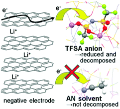 | ||
| Fig. 20 Schematic description of the reductive decomposition near the negatrode in a highly concentrated Li-salt electrolyte.220 (Reprinted with permission from American Chemical Society. Copyright 2014.) | ||
Owing to the unique solution structure with anions and solvent molecules coordinating strongly to Li+ ions, HCEs exhibit enhanced oxidative stability, and inhibit the dissolution of the Al current collector.221–225 It was shown that the 4.45 mol L−1 LiPF6/PC electrolyte improved the cycling performance of the 5.0 V LiNi0.5Mn1.5O4 positrode, while the corresponding dilute electrolyte was easily oxidised and decomposed at such high positive potentials.221
Specially, the simple formulation of the superconcentrated LiN(SO2F2)2/DMC (LiFSA/DMC) electrolyte exhibited remarkably high anodic stability at 5.5 V vs. Li+/Li. Progressive inhibition of anodic Al dissolution was proven by the SEM images (see Fig. 21).222 A high-voltage LiNi0.5Mn1.5O4/graphite battery with this superconcentrated electrolyte exhibited excellent cycling durability with over 90% capacity retention after 100 cycles at 40 °C. In contrast, the cell using the commercial electrolyte retained only 18% of the initial capacity after 100 cycles, indicating severe capacity decay. Besides, compared to the dilute electrolytes, the concentrated 1![[thin space (1/6-em)]](https://www.rsc.org/images/entities/char_2009.gif) :
:![[thin space (1/6-em)]](https://www.rsc.org/images/entities/char_2009.gif) 1.1 LiFSA/DMC electrolytes also showed superior thermal stability and flame retardancy, contributing to the remarkably improved safety properties.
1.1 LiFSA/DMC electrolytes also showed superior thermal stability and flame retardancy, contributing to the remarkably improved safety properties.
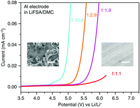 | ||
Fig. 21 LSV of an Al electrode in LiFSA/DMC electrolytes of various concentrations in a three-electrode cell. The scan rate was 1.0 mV s−1. The insets are SEM images of the Al surface polarised in dilute 1![[thin space (1/6-em)]](https://www.rsc.org/images/entities/char_2009.gif) : :![[thin space (1/6-em)]](https://www.rsc.org/images/entities/char_2009.gif) 10.8 (left) and superconcentrated 1 10.8 (left) and superconcentrated 1![[thin space (1/6-em)]](https://www.rsc.org/images/entities/char_2009.gif) : :![[thin space (1/6-em)]](https://www.rsc.org/images/entities/char_2009.gif) 1.1 (right) electrolytes. Many corroding pits cover the surface of the Al electrode polarized in the dilute electrolyte, showing severe anodic Al dissolution. In contrast, no corroding pits appear on the surface of the Al electrode polarised in the superconcentrated electrolyte, indicating the effective inhibition of anodic Al dissolution. The white scale bars in the SEM images represent 20 μm.222 1.1 (right) electrolytes. Many corroding pits cover the surface of the Al electrode polarized in the dilute electrolyte, showing severe anodic Al dissolution. In contrast, no corroding pits appear on the surface of the Al electrode polarised in the superconcentrated electrolyte, indicating the effective inhibition of anodic Al dissolution. The white scale bars in the SEM images represent 20 μm.222 | ||
In addition to the aforementioned HCEs, a new class of highly concentrated Li salt–glyme complexes was established and named as “solvate ionic liquids” with clear classification criteria, because various physicochemical features of such electrolytes were similar to those of ionic liquids.226–232 The Li salt–glyme equimolar mixture had many desirable properties, including ionicity, Li+ ion transference number, Li+ ion concentration, and oxidative stability, in addition to the common properties of ionic liquids. Considering the competition of different glyme solvents and anions (X−) for interactions with Li+ ions, a variety of [Li(glyme)]X complexes could form with different glyme solvents and Li salts. It was found that [Li(glyme)]X with weakly Lewis basic anions (e.g. TFSA− or ClO4−) and longer glymes (e.g. triglyme = G3 or tetraglyme = G4) could form fairly stable complexes.229,231 For example, the electro-oxidation of [Li(glyme)1][TFSA] (triglyme or tetraglyme) took place at ca. 5.0 V vs. Li+/Li, which is obviously more positive than the oxidation potential (ca. 4.0 V) of solutions containing excess glyme molecules ([Li(glyme)x][TFSA], X > 1) (see Fig. 22).227 A further study by ab initio molecular orbital calculations showed that the enhanced oxidative stability could be ascribed to the donation of lone pair electrons of the ether oxygen atom to the Li+ ion, which lowered the highest occupied molecular orbital (HOMO) energy level of the glyme molecule. Additionally, these solvate ionic liquids could be used as efficient electrolytes for Li-ion, Li–S and Li–O2 batteries.226–232
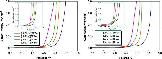 | ||
| Fig. 22 Linear sweep voltammograms of [Li(glyme)x][TFSA] (x = 1, 4, 8, and 20) at a scan rate of 1 mV s−1 at 30 °C. Each inset depicts an enlarged view of current density.227 (Reprinted with permission from American Chemical Society. Copyright 2011.) | ||
Owing to their unique solution structures at certain high concentrations, HCEs have various unusual properties compared to their dilute counterparts, making it unnecessary to rely on the LiPF6 salt for the passivation of the Al current collector, or on the EC solvent for formation of the SEI film on the graphite surface, and providing more design considerations in future battery technologies. Similarly, Na salt based highly concentrated electrolytes may also offer new opportunities for building stable and safe Na-ion batteries.
Safety issue is still a challenge for LIBs because of the intrinsic flammability of organic liquid electrolytes and possibility of leakage. Replacing the organic electrolytes with gel polymer electrolytes (GPEs) delivers a promising solution to improve safety by avoiding these crucial issues.233–235 There are extensively explored GPEs based on polymer matrices that are capable of immobilizing a large amount of liquid electrolytes. These GPEs offer both the flexibility of the polymer and the high ionic conductivity of the liquid electrolyte, and enable wide electrochemical windows, excellent cycling durability and improved thermal stability. GPEs can be formed from different polymer matrices, such as poly(ethylene oxide) (PEO), poly(vinylidene fluoride) (PVDF), PVDF–HFP, and poly(methyl methacrylate) (PMMA).236,237 However, due to the inferior mechanical strength, most GPEs fail to block effectively dendrite growth.238
In this regard, PVDF-based composite GPEs with a cross-linked structure239,240 or a nonwoven fabric241,242 or glass fiber mats (GFMs)243 as a reinforcement scaffold could be a promising solution to improve the mechanical strength. Considering their low cost and high safety, these modified GPEs with enhanced mechanical properties show great possibilities for large-scale and high safety energy storage applications.
3.3. Sodium-ion batteries
Ambient temperature sodium-ion (Na-ion) batteries (SIBs) are promising for large-scale grid energy storage applications based on the wide availability and low cost of sodium.244–246 Although there are many publications on the research and development of different electrode materials, there is little work on new electrolytes used in SIBs.20,247,248 Additionally, it is necessary to design appropriate liquid electrolyte compositions to minimise unwanted interface reactions and to enhance the electrochemical performance and safety in SIBs. Among various aqueous,249,250 organic251 and ionic liquid based choices,252–254 organic electrolytes are more promising owing to their high ionic conductivity, wide electrochemical window and good electrochemical performance.255The most common electrolyte formulations for SIBs include NaClO4 or NaPF6 dissolved in carbonate ester solvents, particularly EC and/or PC.256–259 Various organic electrolytes for SIBs with hard-carbon electrodes have been investigated. The electrochemical properties of hard-carbon in EC:DMC, DME, tetrahydrofuran (THF) and EC:THF solvents containing 1.0 mol L−1 NaClO4 were studied.260 In comparison with carbonate only solvents, THF and the EC:THF mixture were capable of improving the electrochemical performance of hard-carbon electrodes. Unfortunately, oxidation current was observed in the 1.0 mol L−1 NaClO4–THF electrolyte at an onset potential of ca. 4.26 V vs. Na+/Na, indicating the instability of THF-based electrolytes against anodic oxidation.261 Probably because of a combination of historical and cost reasons, most publications on SIB electrolytes are based on NaClO4 as the electrolyte salt. The performance of the hard carbon electrode in cyclic alkylene carbonate and binary solvent electrolytes based on EC and linear carbonate esters containing NaClO4 was studied. It was found that the Na/hard carbon cells with PC and EC:DEC solutions demonstrated a highly reversible capacity of >200 mA h g−1 with excellent capacity retention during 100 cycles.262 A comparative study of diverse electrolyte formulations with different Na salts (NaClO4, NaPF6 and NaTFSI) and solvents (PC, EC, DMC, DME, DEC, THF and triglyme) or solvent mixtures (EC:DMC, EC:DME, EC:PC and EC:triglyme) was reported in terms of ionic conductivity, viscosity, electrochemical window and thermal stability.261 The results showed that the binary EC:PC mixture with dissolved NaClO4 or NaPF6 might be the best electrolyte formulation for the Na/hard carbon cells (see Fig. 23). The same results were confirmed by another group.263 The introduction of dimethyl carbonate (DMC) into EC:PC was found to improve the performance of electrolytes containing these two salts, which was mainly ascribed to the enhanced conductivity resulting from the decrease in viscosity without inducing any significant modification of the SEI composition on the negatrode (Fig. 24).264 Recently, the electrode/electrolyte interface for lithium and sodium metal negatrodes was compared in the 1.0 mol L−1 LiPF6/EC + DMC and 1.0 mol L−1 NaPF6/EC + DMC electrolytes, respectively. Symmetric Li/Li cells exhibited low polarisation and smooth charge–discharge curves at current densities of 0.1 and 1.0 mA cm−2. In contrast, large overpotentials were observed even at 0.1 mA cm−2 in symmetric Na/Na cells, indicating slower electrode kinetics and larger interfacial resistance.265
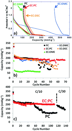 | ||
| Fig. 23 Profiles of (a) first cycle potential vs. capacity and (b) discharge capacity vs. cycle number for hard carbon in 1.0 mol L−1 NaClO4 in various solvent mixtures at C/20. (c) Discharge capacity vs. cycle number for tape-cast hard carbon electrodes in 1.0 mol L−1 NaClO4 in PC alone and EC:PC at C/10 up to 110 cycles and further at C/30.261 (Reproduced with permission from The Royal Society of Chemistry. Copyright 2012.) | ||
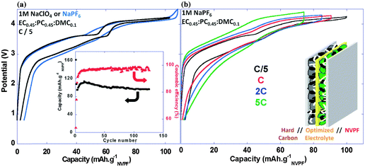 | ||
| Fig. 24 (a) Voltage vs. capacity profiles for NVPF//HC (Na3V2(PO4)2F3//hard carbon) full Na-ion cells in 1.0 mol L−1 NaPF6 or 1.0 mol L−1 NaClO4 in EC0.45:PC0.45:DMC0.1 recorded at C/5 (the inset displays plots of the charge capacity and coulombic efficiency vs. cycle number (C/5; 1.0 mol L−1 NaClO4 in EC0.45:PC0.45:DMC0.1)). (b) Voltage vs. capacity profiles for NVPF//HC full Na ion cells in 1.0 mol L−1 NaPF6 in EC0.45:PC0.45:DMC0.1 recorded at different rates.264 (Reproduced with permission from The Royal Society of Chemistry. Copyright 2013.) | ||
Apart from NaClO4 and NaPF6, other salts, such as sodium bis(trifluoromethane)sulfonimide (NaTFSI), sodium fluorosulfonyl(trifluoromethanesulfonyl)imide (NaFTFSI), sodium bis(fluoro-sulfonyl)imide (NaFSI), NaSO3CF3 (NaOTf), sodium 4,5-dicyano-2-(trifluoromethyl)imidazolate (NaTDI), sodium 4,5-dicyano-2-(pentafluoroethyl)imidazolate (NaPDI), and sodium difluoro-(oxalato)borate (NaDFOB), were also investigated.251,266,267 Of these salts, NaTDI and NaPDI were both found to be thermally stable up to more than 300 °C, and the measured conductivity of their solutions in PC (about 4 mS cm−1) was notably lower than that of the commercially available salt, LiClO4 (8 mS cm−1).266
Comparative studies were reported on electrolytes based on commercially available sodium salts, namely NaPF6, NaClO4 and NaCF3SO3, in a binary mixture of EC and DMC.268 It was found that the ionic conductivities of the two solutions of 0.6 mol L−1 NaPF6 and 1.0 mol L−1 NaClO4 in EC and DMC were 6.8 and 5.0 mS cm−1, respectively. These values are somewhat higher than that of NaOTf (3.7 mS cm−1, 0.8 mol L−1). Unfortunately, NaOTf-, NaFSI- and NaTFSI-based electrolytes had the major drawback of being unable to form a passivation layer on the Al current collector.268,269 A systematic evaluation of the intrinsic Al stability in electrolytes based on various NaX [X = PF6, ClO4, TFSI, FTFSI, FSI] salts dissolved in solvent mixtures showed a trend of the Al dissolution increasing in the order of NaPF6 < NaClO4 < NaTFSI < NaFTFSI < NaFSI.270
When adding 5 wt% NaPF6 to the base electrolyte, the stability of Al in imide-based electrolytes could be improved, which may be attributed to the formation of a protective passivation layer on the Al surface. Notably, compared to NaClO4 and NaPF6 (see Fig. 25), NaDFOB not only possesses excellent compatibility with various common solvents used in SIBs, but also has good stability. It will also not generate toxic or dangerous products when exposed to air and water, indicating that NaDFOB may be a prospective Na salt for application in high performance electrolytes for future SIBs.271
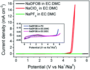 | ||
| Fig. 25 CVs of Na-ion cells with electrolytes of 1.0 mol L−1 NaX (X = DFOB, ClO4, and PF6) in EC:DMC at room temperature at a scan rate of 1.0 mV s−1. The inset shows the CVs of the cells with electrolytes of NaDFOB in PC, EC:DEC, and EC:DMC, respectively.271 (Reproduced with permission from The Royal Society of Chemistry. Copyright 2015.) | ||
A new high-voltage electrolyte was developed from NaClO4 in mixed ethyl methanesulfonate (EMS) and FEC.272 The anodic stability of this electrolyte could be increased to 5.6 V vs. Na+/Na, which is higher than that of the PC-based electrolyte of 4.5 V. Moreover, the EMS-based electrolyte had a slightly higher ionic conductivity of 6.3 mS cm−1 at 25 °C. In this high-voltage electrolyte, the 4.0 V positrode of Na[Ni0.25Fe0.5Mn0.25]O2 was found to have much improved electrochemical performance.
On the other hand, to bypass the flammability of organic carbonate electrolytes, a safer Na-ion battery was proposed and demonstrated based on a nonflammable electrolyte of trimethyl phosphate (TMP) coupled with a NaNi0.35Mn0.35Fe0.3O2 positrode and a Sb-based negatrode (see Fig. 26).273 The results showed that the TMP-based electrolyte with FEC additive was totally nonflammable. It also offered a wide electrochemical window of 4.5 V and good compatibility with both the Sb-based negatrode and the NaNi0.35Mn0.35Fe0.3O2 positrode, promising a new technical prospect to meet the high-capacity and high-safety requirements for large-scale energy storage applications.
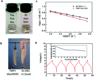 | ||
Fig. 26 (a) Room temperature storage behaviour of the TMP + 10 vol% FEC electrolyte. (b) Combustion behaviour of the TMP electrolyte and carbonate electrolyte. (c) Temperature dependence of the ionic conductivities of 0.8 mol L−1 NaPF6/TMP + 10 vol% FEC electrolyte. The ionic conductivity of 1.0 mol L−1 NaPF6 EC/DEC (1![[thin space (1/6-em)]](https://www.rsc.org/images/entities/char_2009.gif) : :![[thin space (1/6-em)]](https://www.rsc.org/images/entities/char_2009.gif) 1) electrolyte is also shown for comparison. (d) Charge/discharge curves and cycling performance (inset) of Sb/NaNi0.35Mn0.35Fe0.3O2 cells in the 0.8 mol L−1 NaPF6/TMP + 10 vol% FEC electrolyte.273 1) electrolyte is also shown for comparison. (d) Charge/discharge curves and cycling performance (inset) of Sb/NaNi0.35Mn0.35Fe0.3O2 cells in the 0.8 mol L−1 NaPF6/TMP + 10 vol% FEC electrolyte.273 | ||
The progress in the development of electrolyte additives for SIBs is even slower than that for LIBs. Currently, hard carbon is the most widely used negatrode material in SIBs, exhibiting an initial reversible capacity of 300 mA h g−1 in 1.0 mol L−1 NaClO4/EC + DEC (3![[thin space (1/6-em)]](https://www.rsc.org/images/entities/char_2009.gif) :
:![[thin space (1/6-em)]](https://www.rsc.org/images/entities/char_2009.gif) 7, by vol.) in the potential range of 0 to 2.0 V vs. Na+/Na.274
7, by vol.) in the potential range of 0 to 2.0 V vs. Na+/Na.274
However, the hard carbon electrode showed a significant loss of capacity as galvanostatic cycling continued. It may be due to the high reactivity of sodium inserted hard carbon (Na@HC) which suffered from continuous and corrosive attack by the commonly used organic electrolytes, rather than forming a stable SEI, resulting in degradation of cell performance.275
It is commonly known that addition of film-forming additives into the electrolyte can be an effective and easiest strategy to improve the electrode performance in LIBs.276–279 A comparative study was carried out to understand how different electrolyte additives, such as FEC, trans-difluoroethylene carbonate (DFEC), ethylene sulfite (ES) and vinylene carbonate (VC), could affect the electrochemical performance of hard carbon electrodes in SIBs.280 It was found that only FEC could help form a stable passivation film at ca. 0.7 V on the hard carbon or sodium metal surfaces, resulting in sufficiently suppressed capacity degradation in comparison with electrolytes without FEC (Fig. 27). Later, the influence of the addition of FEC into the 1.0 mol L−1 NaClO4/EC + PC electrolyte on the electrochemical performance of hard carbon electrodes was reported.281 In the presence of 2.0% FEC additive, a decrease of the reversible capacity and coulombic efficiency was observed. Additionally, FEC was used as an SEI formation additive for Sb/C,282,283 amorphous P,284 Sn4P3,285 and other negatrodes,286 and demonstrated a variety of benefits in terms of the cycling performance and effective passivation of SIB negatrodes.
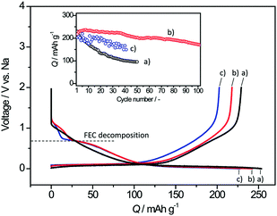 | ||
| Fig. 27 Initial reduction/oxidation curves of hard-carbon electrodes in 1.0 mol L−1 NaClO4 PC solution (a) without and with (b) 2.0 vol% and (c) 10.0 vol% FEC at a rate of −25 and +25 mA g−1 in coin-type Na-ion cells. The inset shows the variation of reversible oxidative capacities of hard carbon during successive cycling tests.280 (Reprinted with permission from American Chemical Society. Copyright 2011.) | ||
Recently, a double-layer SEI film mechanism was proposed for the Sb-based alloy negatrodes in the FEC-containing electrolyte. According to this mechanism, FEC in the electrolyte first decomposes to form a dense and thin SEI film (first-layer film), and then other solvents further decompose on the first-layer film to form a double-layer SEI film in the more negative potential region, resulting in improved performance of the negatrodes (see Fig. 28).283 Thereby, FEC is an effective film-forming additive for modifying the SEI film and improving the cyclability of the negatrode materials in SIBs. It is also noted that only 5% ethoxy(pentafluoro)cyclotriphosphazene (EFPN) addition is sufficient to make the carbonate-based electrolyte totally non-flammable, which can help improve the safety of organic SIBs.287 On the other hand, the use of gel polymer electrolytes (GPEs) to replace flammable organic electrolytes has also been proposed to address the safety concerns and avoid liquid leakage for SIBs.288–290 The first report indicated that a Na+ ion conducting GPE based on poly(vinylidene difluoride-co-hexafluoropropylene) (PVDF–HFP) was prepared by a simple phase separation process, and showed an acceptable ionic conductivity of 0.60 mS cm−1, good mechanical properties and good electrochemical stability.288 Then, a Na-ion capacitor assembled with this GPE provided a high specific energy of 168 W h kg−1 and stable cycling with 85% of the specific capacitance maintained after 1200 cycles.234 Also, a Na-ion battery Sb/Na3V2(PO4)3 with a low-cost GPE based on cross-linked PMMA was demonstrated. The cell exhibited a highly reversible electrochemical reaction and a stable cycle performance, which was attributed to the enhanced interfacial properties of the gel–polymer electrolyte, especially at the evaluated temperature.290
 | ||
| Fig. 28 Left: Cycling performance of the SiC–Sb–C electrode at a cycling current of 100 mA g−1 in FEC-free and FEC-containing electrolytes; right: structural scheme of the film-forming mechanism of the SiC–Sb–C electrode in the FEC-free (right-a) and FEC-containing electrolyte (right-b).283 (Reprinted with permission from Elsevier. Copyright 2016.) | ||
For development of SIBs, more research is needed to design and prepare new electrolytes and improve existing ones in terms of sodium salts, solvents and additives. Theoretically, it is important to understand the reaction mechanisms at the electrode/electrolyte interface, so as to achieve more stable cycling performance of organic SIBs.
3.4. Magnesium batteries
The first rechargeable battery with a Mg metal negatrode and a Mo6S8 positrode, as shown in Fig. 29, was only demonstrated recently,293 but has gained increasing attention due to the high volumetric capacity of Mg = Mg2+ + 2e (3832 mA h cm−3), abundant resource, low material cost, and more importantly easier control of the electrodeposition of the Mg metal without dendrite formation.291–293 The last point differentiates Mg from both Li and Na in that it is not required to use an intercalation host, but the Mg metal itself can be used directly as the negatrode to couple with a suitable positrode in a rechargeable battery. For this reason, the term “magnesium battery” is more appropriate than “magnesium ion battery”. This nature of Mg electrochemistry brings about other benefits, such as higher device energy density (no interaction host material) and safer operation (no short circuit due to dendrite growth).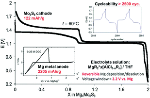 | ||
| Fig. 29 Operation scheme of the first working rechargeable Mg battery prototype.292 (Reproduced with permission from The Royal Society of Chemistry. Copyright 2013.) | ||
However, since the nonconductive ion-blocking layers formed on the Mg surface in non-aqueous, polar aprotic electrolytes cannot transport Mg2+ ions effectively, it is crucial to develop a suitable solvent–salt combination with reversible Mg electrodeposition and stripping, and wide electrochemical windows.294,295 The challenge to commercialise rechargeable Mg batteries is to develop anodically stable and Mg2+ ion conducting electrolytes which govern the electrode and cell performances.296 In fact, it was known long ago that the solutions of organomagnesium salts and complexes in ethers or tertiary amines were compatible with the Mg negatrode, allowing for reversible Mg deposition and dissolution.297 Afterwards, highly inert ethereal solvents, such as tetrahydrofuran (THF), dimethoxyethane (DME) and tetraglyme, became more popular solvents that are compatible with Mg and all other battery components.298,299
Extensive research efforts have been dedicated to designing the salts, which must be highly soluble in these nonpolar solvents and electrochemically stable. Early studies indicated that although offering high charge density by the Mg2+ ion, simple Mg salts such as Mg(ClO4)2 or Mg(PF6)2 failed to work in Mg batteries as the respective anions decomposed on and passivated the Mg metal surface.300,301
Interestingly, nearly 100 years ago, the Grignard reagent was studied as an electrolyte that allowed etching of the passivating oxide coating and hence reversible deposition and dissolution of Mg on the negatrode.302 However, Grignard reagents (RMgX, where R is an alkyl or aryl group, and X is Cl or Br) cannot be used in batteries due to their intrinsic reducing power. The first non-Grignard electrolyte comprised of Mg(BR2R′2)2 (where R and R′ can be various organic groups) in THF, which has been considered as the first major breakthrough in Mg battery electrolytes.297 Later on, a family of dichloro complex (DCC) electrolytes were proposed based on the products of the transmetalation reaction of the Lewis base RxMgCl2−x with a variety of Lewis acids R′yAlCl3−y (R, R′ = n-butyl and/or ethyl, x = 0–2, y = 0–3) in THF.303–306 In 2000, the first prototype of the rechargeable Mg battery was demonstrated, signifying the second breakthrough in this area.307 This prototype with a DCC (Mg(AlCl2BuEt)2 = Bu2Mg·2EtAlCl2) as the electrolyte achieved a high coulombic efficiency of up to 99%. This electrolyte has an acceptable conductivity of few mS cm−1 but unfortunately a narrow electrochemical window of ca. 2.2 V which is incompatible with high-voltage positrode materials.
To enlarge the electrochemical window of DCC electrolytes without hampering the ionic conductivity, more varieties of DCC were synthesised by substituting the ethyl groups on the Lewis acid with a methyl or phenyl group.308–310 For example, the optimal composition of the THF solution of the (PhMgCl)2·AlCl3 complex showed an improved anodic stability up to 3.0 V.308 When using the phenyl group as the organic ligand, the DCC comprising the products of the reaction between PhxMgCl2−x and PhyAlCl3−y is known as the all phenyl complex (APC, see Fig. 30) electrolyte.308–310
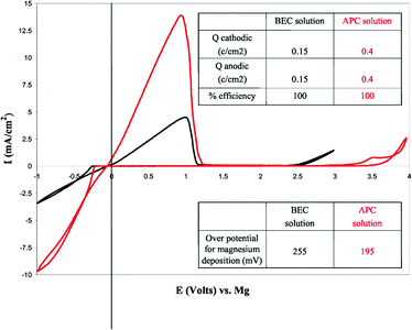 | ||
Fig. 30 Comparison of cyclic voltammograms (CVs) of THF solutions containing 0.25 mol L−1 of the reaction product between 1![[thin space (1/6-em)]](https://www.rsc.org/images/entities/char_2009.gif) : :![[thin space (1/6-em)]](https://www.rsc.org/images/entities/char_2009.gif) 2 MgBu2 and AlCl2Et (butyl–ethyl complex (BEC), standard solutions, black line) and 0.4 mol L−1 of the reaction product between 1 2 MgBu2 and AlCl2Et (butyl–ethyl complex (BEC), standard solutions, black line) and 0.4 mol L−1 of the reaction product between 1![[thin space (1/6-em)]](https://www.rsc.org/images/entities/char_2009.gif) : :![[thin space (1/6-em)]](https://www.rsc.org/images/entities/char_2009.gif) 2 AlCl3 and PhMgCl (all phenyl complex electrolyte, red line) as indicated. 25 mV s−1, Pt wire working electrode, 25 °C. Relevant quantitative information is given in the two inserted tables.308 (Reprinted with permission from The Electrochemical Society. Copyright 2008.) 2 AlCl3 and PhMgCl (all phenyl complex electrolyte, red line) as indicated. 25 mV s−1, Pt wire working electrode, 25 °C. Relevant quantitative information is given in the two inserted tables.308 (Reprinted with permission from The Electrochemical Society. Copyright 2008.) | ||
In particular, the APC-THF electrolyte containing the reaction product (0.4 mol L−1) between 1![[thin space (1/6-em)]](https://www.rsc.org/images/entities/char_2009.gif) :
:![[thin space (1/6-em)]](https://www.rsc.org/images/entities/char_2009.gif) 2 AlCl3 and PhMgCl displayed a significantly broader electrochemical window up to 3.3 V on a Pt working electrode and a coulombic efficiency of 100% for reversible deposition of Mg. Additionally, this APC electrolyte exhibited a conductivity of 2 mS cm−1.311
2 AlCl3 and PhMgCl displayed a significantly broader electrochemical window up to 3.3 V on a Pt working electrode and a coulombic efficiency of 100% for reversible deposition of Mg. Additionally, this APC electrolyte exhibited a conductivity of 2 mS cm−1.311
The reaction of Grignard hexamethyldisilazide magnesium chloride (HMDSMgCl) with a Lewis acid AlCl3 in a 3![[thin space (1/6-em)]](https://www.rsc.org/images/entities/char_2009.gif) :
:![[thin space (1/6-em)]](https://www.rsc.org/images/entities/char_2009.gif) 1 ratio led to a product that could significantly raise the oxidation potential to 3.2 V without compromising the coulombic efficiency.312 The product was isolated as crystals of [Mg2(μ-Cl)3·6THF] (HMDSAlCl3) with a structure as shown in Fig. 31.
1 ratio led to a product that could significantly raise the oxidation potential to 3.2 V without compromising the coulombic efficiency.312 The product was isolated as crystals of [Mg2(μ-Cl)3·6THF] (HMDSAlCl3) with a structure as shown in Fig. 31.
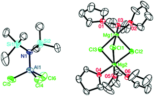 | ||
| Fig. 31 ORTEP plot (25% thermal probability ellipsoids) of the crystallised product, (Mg2(μ-Cl)3·6THF)(HMDSAlCl3).311 | ||
In addition, it should be noted that the electrolyte of tri(3,5-dimethylphenyl)borane (Mes3B)·(PhMgCl)2 in THF exhibited a wide electrochemical window >3.5 V. It was found to be capable of assisting very well the electrochemical performance of the Mg/Mo6S8 battery.313
Very recently, the first inorganic compound, magnesium aluminium chloride complex (MACC), was synthesised via the acid–base reaction of MgCl2 with Lewis acidic compounds such as AlCl3, which demonstrated a high coulombic efficiency (up to 99%), low deposition overpotential (<200 mV), and good anodic stability (3.1 V vs. Mg/Mg2+). Despite the good performance achieved with all the above reported electrolytes, corrosion of aluminium and stainless steel current collectors posed by the presence of halide ions had hampered the commercialisation of these batteries.314 Therefore, the development of halide-free salts with high reductive stability is crucial for realising a practical rechargeable Mg battery. A new class of Mg(BH4)2 based electrolytes was proposed for use in rechargeable Mg batteries.315 When dissolved in both THF and DME, the electrolyte enabled reversible Mg deposition and stripping, and enhanced stability on the current-collector materials. However, the oxidative stability on Pt at 1.7 V vs. Mg limits the use of Mg(BH4)2 with high-voltage positrodes.
A later study on synthesis and test of closo-borane magnesium dodecahydrododecaborate (MgB12H12) found high stability for use in Mg batteries, but it was virtually insoluble in ethers. In contrast, another synthetic salt, [1-(1,7-C2B10H11)]MgCl, showed good solubility in THF with remarkably high anodic stability (ca. 3.2 vs. Mg).316 Further, a new boron cluster anion, monocarborane CB11H12−, which was compatible with Mg (>99% coulombic efficiency), showed great anodic stability at 3.8 V vs. Mg, and was non-corrosive (see Fig. 32).317 A MnO2 positrode using the Mg(CB11H12)2/tetraglyme electrolyte could be charged up to 3.5 V, while the cell using the APC electrolyte could only be charged to around 2.5 V due to corrosion. Owing to their outstanding properties, Mg(CB11H12)2 salt-based electrolytes are very promising for future design of high voltage Mg batteries.
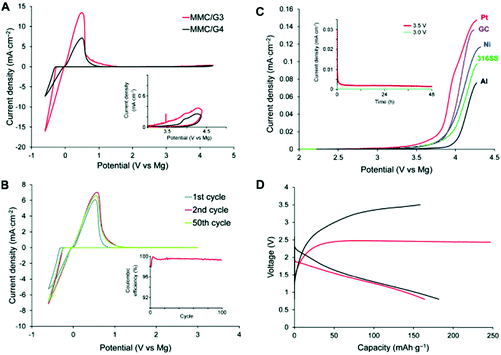 | ||
| Fig. 32 (A) First scan CVs of 0.75 mol L−1 MMC/G3 and 0.75 mol L−1 MMC/G4 (MMC: magnesium monocarborane, Mg(CB11H12)2; G3: triglyme; G4: tetraglume) on a Pt electrode collected at 5 mV s−1 (inset: enlargement of the 3.0 to 5.0 V region). (B) Selected CVs of 0.75 mol L−1 MMC/G4 electrolyte on a Pt electrode collected within the potential range of −0.6 to 3.0 V (vs. Mg/Mg2+) at 5 mV s−1 (inset: cycling efficiencies of Mg deposition and dissolution). (C) Linear sweep voltammograms of different electrode materials in the 0.75 mol L−1 MMC/G4 electrolyte at a scan rate of 5 mV s−1 (inset: chronoamperometry of a 316 stainless steel disk electrode (area = 1.33 cm2) in the 0.75 mol L−1 MMC/G4 electrolyte at 3.0 V (light blue) and 3.5 V (brown) vs. Mg/Mg2+). (D) Initial discharge–charge profiles of a rechargeable Mg battery with 0.75 mol L−1 MMC/G4 (black line) and 0.2 mol L−1 APC (red line) as the electrolyte, a Mg negatrode, and an α-MnO2 positrode under a constant current density of 0.2 mA cm−2.317 (Reprinted with permission from Wiley-VCH Verlag GmbH & Co. KGaA, Weinheim. Copyright 2007.) | ||
4. Ionic liquid electrolytes
Although organic electrolytes can offer wide operating voltages which are beneficial to EES devices, they show several significant problems, such as maintenance difficulty (volatile, tedious purification processes), higher environmental impact, higher cost (both materials and manufacture), safety issues (explosion risks due to the poor thermal stability), and low ionic conductivity (diminished power capability).Among all the available electrolytes, ionic liquids show the highest operating voltage up to 6.0 V, although the working range is often from 2.5 V to 4.0 V. It is directly related to the energy capacity and performance of EES devices, particularly supercapacitors. Unfortunately, ionic liquids are usually less conductive than their high temperature counterparts, molten salts, as discussed in the next section. This is mainly because ions in ionic liquids are very large and hence unable to move fast. A recently produced graphene based supercapacitor with an ionic liquid as the electrolyte has demonstrated a specific energy of up to 136 W h kg−1 at 80 °C, comparable to that of a commercial Li-ion battery.318 This high specific energy is mainly due to the high working voltage of 4.0 V. Fig. 33 demonstrates the galvanostatic charge–discharge curve of a curved graphene electrode (6.6 mg) at a constant specific current of 1 A g−1, and CVs for the graphene electrode at different scan rates. All these electrochemical tests were done in an ionic liquid, 1-ethyl-3-methylimidazolium tetrafluoroborate (EMIMBF4), as the electrolyte.
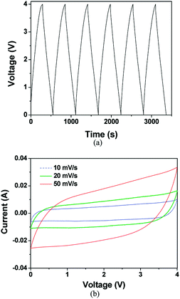 | ||
| Fig. 33 (a) Galvanostatic charge–discharge curve at 1 A g−1 and (b) CVs at different scan rates recorded on a curved graphene electrode in an ionic liquid, EMIMBF4.318 (Reproduced with permission from American Chemical Society. Copyright 2010.) | ||
In this example, the mesoporous graphene electrode enabled fast capacitive charging and discharging, and unusually high specific capacitance. Coupled with this electrode material, the ionic liquid electrolyte supported an operating voltage of 4.0 V, pushing the specific energy of the EDLC to an unprecedented level at the time of the report.
Similar applications of ionic liquids as the electrolyte in supercapacitors and supercapatteries were also reported.319,320Fig. 34 shows a very recent study demonstrating a supercapattery based on an activated carbon positrode and a Li negatrode in an ionic liquid, 1-butyl-1-methylpyrrolidinium tri(pentafluoroethyl)tri-fluorophosphate (BMPyrrFAP), containing gamma-butyrolactone (γ-GBL) and LiClO4.320 The remarkably high specific energy of 230 W h kg−1 can be mainly attributed to the broad operating voltage up to 4.3 V. However, simply substituting an aqueous or organic electrolyte with an ionic liquid would not always lead to high energy capacity. Inferior results from ionic liquid electrolytes in supercapacitors are not uncommon and are largely related to the reduced specific capacitance of the electrode materials in the ionic liquid. Therefore, the properties of ionic liquid electrolytes need improvement to closely match with those of the electrode materials and cell design.
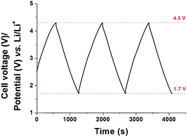 | ||
| Fig. 34 Galvanostatic charge–discharge curves of a demonstrative ionic liquid based supercapattery cell at 1 mA cm−2.320 | ||
It is commonly thought that dendrite formation is inevitable when a metal is used as the negatrode in batteries or supercapatteries, which could shorten the cycling life of the devices. The worst scenario is that the dendrite penetrates through the separator membrane, forming an internal short-circuit between the positrode and negatrode and leading to fire or explosion. However, a recent study has shown that pre-treatment of the Li metal in ionic liquids containing an appropriate lithium salt can effectively suppress the formation of the Li metal dendrite during charge–discharge cycling.321
Typical results from this study are presented in Fig. 35 which plots the discharge capacity and coulombic efficiency of several “Li(−)|Li-salt + ionic liquid|LiFePO4(+)” cells against the charge–discharge cycle number at a rate of 1C. The low viscosity ionic liquid used in the cell was N-propyl-N-methyl-pyrrolidinium bis(fluorosulfonyl)imide, [C3mPyr+][FSI−]. A Li-salt, LiFSI (Fig. 35a and b), LiPF6 (Fig. 35c) or LiAsF6 (Fig. 35d), was added to the ionic liquid to form the electrolyte. The negatrode was either pristine, untreated Li metal (Fig. 35a), or pre-treated Li metal (Fig. 35b–d) by immersing it in the respective electrolyte for 12 days.
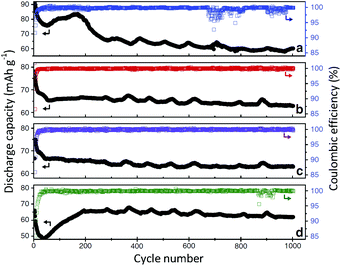 | ||
| Fig. 35 Variations of discharge capacity and coulombic efficiency with the cycle number of charging and discharging of the “Li|Li-salt + [C3mPyr+][FSI−]|LiFePO4” cell at a rate of 1C under different conditions: (a) Pristine Li metal, LiFSI; (b–d) Li metal immersed in [C3mPyr+][FSI−] containing (b) LiFSI, (c) LiPF6, or (d) LiAsF6 for 12 days before cell assembly.321 | ||
It can be seen in Fig. 35 that all the four cells show initially unstable and then gradually declining discharge capacity which becomes stable beyond about 500 cycles. This unstable initial behaviour corresponded possibly to the variation of the SEI layer on the Li negatrode. For the cell with the untreated Li metal negatrode (Fig. 35a), the stable discharge capacity is just below 60 mA h g−1, whilst all the other cells with the pre-treated Li metal negatrode exhibit notably higher stable discharge capacities. The more significant difference is shown in the coulombic efficiency profiles. For the untreated Li metal negatrode, the coulombic efficiency becomes widely scattered after about 600 cycles, indicating gradual formation of dendrites which are unfavourable for maintaining the dynamic stability of the SEI layer. However, the coulombic efficiency remains much more constant for the cells with the pre-treated Li negatrode. This change can be attributed to the pre-formed SEI on the Li negatrode contributing to elimination of dendrite formation during charge–discharge cycling. It should be mentioned that Fig. 35d also shows some scattered points in the coulombic efficiency profile after about 820 cycles. This is evidence that anions in the ionic liquid electrolyte can impact the SEI stability, suggesting the FSI− and PF6− ions to be more effective for stabilising the SEI layer on the Li negatrode.
5. Molten salt electrolytes
Molten salts are classified as ‘high-temperature’ liquid salts with reference to ionic liquids that are in the liquid state at room temperature. The distinguishing properties of molten salts, which include but not limited to high ionic conductivity, high chemical and thermal stability, and high mutual solubility, enable their wide applications in the construction of EES devices. Molten salt electrolytes offer many advantages over their aqueous counterparts, such as higher working voltage and no detrimental effects from hydration of ions. Because molten salt based EES devices operate at elevated temperatures, both kinetic and thermodynamic barriers can be minimised, and hence a relatively high efficiency for energy conversion is expected. This section describes and analyses four typical examples of molten salt based EES devices, which are ZEBRA molten salt batteries, liquid metal batteries, carbonate fuel cells, and direct carbon fuel cells.5.1. ZEBRA molten salt batteries
The ZEBRA molten salt battery, which is named after a technical project, Zero Emissions Batteries Research Activity,322 has been considered as one of the most attractive EES devices for both transportation (e.g., automobile) and stationary (e.g., renewable energy storage) applications.323,324 The working mechanism of the ZEBRA molten salt battery can be described by the following electrochemical reactions:| (+) positrode: NiCl2 + 2Na+ + 2e− = Ni + 2NaCl |
| (−) negatrode: 2Na = 2Na+ + 2e− |
| Cell: NiCl2 + 2Na = Ni + 2NaCl |
According to the cell reaction and thermodynamic data at 300 °C (ΔG° = −138.51 W h), the theoretical cell voltage and specific energy of the ZEBRA molten salt battery can be respectively calculated to be 2.584 V and 789 W h kg−1 (counting only the total mass of the active materials on both electrodes). In practical cells, the use of an electrolyte, current collectors, and thermal insulating and packaging materials is inevitable. As a result, the reported specific energy of real ZEBRA batteries range from 90 to 120 W h kg−1 with the energy efficiency close to 100%.323
As can be seen from Fig. 36, the construction of the ZEBRA battery is similar to that of a sodium–sulphur battery in that both use a liquid sodium negatrode and the β-Al2O3 solid electrolyte. This makes the development of the ZEBRA battery much easier as it can adopt the existing mature technologies. On the other hand, in comparison with the sodium–sulphur battery, the ZEBRA battery uses an additional molten salt electrolyte to bridge between the β-Al2O3 solid electrolyte and positrode. The molten salt is NaAlCl4 which enables not only ionic conduction, but also the reversible conversion between Ni and NiCl2 in solid state on the positrode during discharging and charging. The operating temperature of a ZEBRA battery is between 170 °C and 400 °C, which enables high power capability.323 By taking advantage of the molten NaAlCl4, the corrosion issue arising from the sodium polysulfides in the sodium–sulphur battery can be avoided. This property of NaAlCl4 also contributes, at least partly, to the long cycle life of the ZEBRA battery which is typically designed to work over 10 years.323,324
5.2. Liquid metal batteries
Due to the unique liquid–liquid electrode–electrolyte interfaces and highly conductive molten salt electrolytes, the liquid metal batteries are endowed with ultrafast electrode charge-transfer kinetics and superior ion transport properties.325 The structure of a liquid metal battery is illustrated in Fig. 37.As can be seen from Fig. 37, the molten salt electrolyte in a typical liquid metal battery is sandwiched between two liquid–metal electrodes, i.e., positrode and negatrode. Therefore, the liquid metal battery cell can be described as follows:325
| A(l)|AXz(l)|A–B(l) |
The electrochemical reactions in a liquid metal battery during discharging can be written as follows:
| (+) positrode: Az+ + B(l) + ze− = A–B(l) |
| (−) negatrode: A(l) = Az+ + ze− |
| Cell: A(l) + B(l) = A–B(l) |
According to the construction shown in Fig. 37, the characteristics of the molten salt electrolyte have to meet some specific criteria. First, the density of the electrolyte should fall in between those of the positrode and negatrode, with the intention of self-segregation of the three liquid layers. Second, the ionic conductivity of the molten salt should be high, which is crucial for increasing the energy efficiency and power capability. Third, the solubility of metallic electrodes in the electrolyte should be as low as possible. The high solubility of metallic electrodes in the molten salt will bring about electronic conduction and self-discharge, leading to low current and energy efficiency.
The solubility of alkali and alkaline-earth metals in their respective halide salts has been evaluated and summarised by many researchers.325–328 It has been found that with increasing atomic number, the solubility of both liquid alkali and alkaline-earth metals in their respective halide salts increases, i.e., Li < Na < K < Rb < Cs, and Mg < Ca < Sr < Ba, respectively.
In the same way, the liquid metal solubility also increases with increasing halide atomic number, i.e., F < Cl < Br < I.325 In order to minimise the solubility of metals in the molten salt, the cell operating temperature should be maintained at a relatively low value. Therefore a relatively low melting point of the molten salt electrolyte is vital. In the interest of the low melting point, eutectic mixtures of salts (binary, ternary, and quaternary) have been investigated intensively,325,329,330 which could also help to minimise the associated issues with the high operating temperatures, including side reactions, high cost of refractory cell materials, difficulties in device sealing, and safety concerns. During recent years, a unique binary electrolyte consisting of NaOH and NaI (molar ratio of ca. 0.8 to 0.2) has been developed, which shows a low eutectic melting temperature of 220 °C.331 Another characteristic of the molten salt electrolyte, which should be considered, is the decomposition voltage. A high decomposition voltage is desired as it could render high charging and discharging voltages.325Table 1 lists the properties of some commonly used low melting point molten halide salt electrolytes.
| Cation | Electrolyte | Composition, mol% | T m, °C | ρ(T0), g cm−3 | σ(T0), S cm−1 | T 0, °C |
|---|---|---|---|---|---|---|
| Li+ | LiCl–KCl | 41![[thin space (1/6-em)]](https://www.rsc.org/images/entities/char_2009.gif) : :![[thin space (1/6-em)]](https://www.rsc.org/images/entities/char_2009.gif) 59 59 |
353 | 1.63 | 1.7 | 476 |
| LiF–LiCl–LiI | 20![[thin space (1/6-em)]](https://www.rsc.org/images/entities/char_2009.gif) : :![[thin space (1/6-em)]](https://www.rsc.org/images/entities/char_2009.gif) 50 50![[thin space (1/6-em)]](https://www.rsc.org/images/entities/char_2009.gif) : :![[thin space (1/6-em)]](https://www.rsc.org/images/entities/char_2009.gif) 30 30 |
430 | ||||
| LiCl–LiI | 35![[thin space (1/6-em)]](https://www.rsc.org/images/entities/char_2009.gif) : :![[thin space (1/6-em)]](https://www.rsc.org/images/entities/char_2009.gif) 65 65 |
368 | 2.57 | 3.5 | 450 | |
| Na+ | NaF–NaCl–NaI | 15![[thin space (1/6-em)]](https://www.rsc.org/images/entities/char_2009.gif) : :![[thin space (1/6-em)]](https://www.rsc.org/images/entities/char_2009.gif) 16 16![[thin space (1/6-em)]](https://www.rsc.org/images/entities/char_2009.gif) : :![[thin space (1/6-em)]](https://www.rsc.org/images/entities/char_2009.gif) 53 53 |
530 | 2.54 | 1.7–2.0 | 560 |
| Mg2+ | NaCl–KCl–MgCl2 | 30![[thin space (1/6-em)]](https://www.rsc.org/images/entities/char_2009.gif) : :![[thin space (1/6-em)]](https://www.rsc.org/images/entities/char_2009.gif) 20 20![[thin space (1/6-em)]](https://www.rsc.org/images/entities/char_2009.gif) : :![[thin space (1/6-em)]](https://www.rsc.org/images/entities/char_2009.gif) 50 50 |
396 | |||
| Ca2+ | LiCl–NaCl–CaCl2–BaCl2 | 29![[thin space (1/6-em)]](https://www.rsc.org/images/entities/char_2009.gif) : :![[thin space (1/6-em)]](https://www.rsc.org/images/entities/char_2009.gif) 20 20![[thin space (1/6-em)]](https://www.rsc.org/images/entities/char_2009.gif) : :![[thin space (1/6-em)]](https://www.rsc.org/images/entities/char_2009.gif) 35 35![[thin space (1/6-em)]](https://www.rsc.org/images/entities/char_2009.gif) : :![[thin space (1/6-em)]](https://www.rsc.org/images/entities/char_2009.gif) 16 16 |
390 | 2.28 | 1.9 | 527 |
Recently, several types of molten salt based liquid metal batteries are being developed, including Mg|MgCl2–KCl–NaCl|Sb,332 Ca|LiCl–NaCl–CaCl2|Bi,333 CaLiCl–NaCl–CaCl2|Sb,334 Na|NaOH–NaI|Pb–Bi335 and Li|LiCl–LiF|Bi.336 In these liquid metal batteries, Mg, Ca, Na, and Li have been used as the reactive elements on the negatrode, whereas Sb, Bi, and Pb–Bi have been utilised as the positrode materials due to their relatively low melting temperatures. These molten salt based liquid metal battery systems exhibited remarkable performances, e.g. long life cycle, high efficiency, and low fading rate (i.e. high capacity retention). Fig. 38 shows the full cell cycling performance of a Li|LiCl–LiF|Bi cell.336 After 1000 cycles, 99.9% of the coulombic efficiency remained, and only 4% loss of capacity was observed. This cell was even tested by cooling to the solidified state, followed by heating and recycling.336
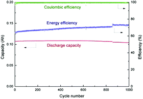 | ||
| Fig. 38 Full cell cycling performance for a Li|LiCl–LiF|Bi cell at 550 °C. Cell diameter: 1.2 cm, theoretical capacity: 0.115 A h, at 0.3 A cm−2.336 | ||
5.3. Molten carbonate fuel cells
Current designs of various fuel cells are for primary use, i.e. they function only to convert chemical energy to electricity (discharging), but are not able to reverse the process (charging). Thus, fuel cells are not, strictly speaking, EES devices. This is particularly the case when the fuel is small organic molecules, such as methanol and formic acid, and the fuel oxidation reaction is practically not possible to reverse electrochemically, and not even chemically. However, when the fuel is hydrogen or carbon, the oxidation reaction can be chemically or even electrochemically reversed. Therefore, these fuel cells present good opportunities for EES applications. Two examples that are relevant to molten salts are explained in this and next sections: molten carbonate fuel cells and direct carbon fuel cells.The molten carbonate fuel cells (MCFCs) use hydrogen as the fuel and have exclusive superiority over other types of fuel cells. The MCFCs could be employed to contribute substantially to the reduction of CO2 emissions from combustion flue gas.337 This ability of MCFCs is attractive to the ongoing global effort to mitigate the impact of CO2 emission on climate change. Apart from this, the MCFC has been considered as the most successful major fuel cell. For example, there are more than 50 MCFC based stationary power stations being commissioned around the world producing over 300 MW of clean electric powder.338Fig. 39 shows the schematic drawing of an MCFC.
As shown in Fig. 39, CO2 is consumed by the cathodic reactions on the positrode side (typical positrode material: lithiated nickel oxide). Meanwhile the anodic reactions release CO2 on the negatrode side (typical negatrode material: Ni, alloyed with chromium or aluminium). A eutectic mixture of Li2CO3 and K2CO3 is commonly utilised as the electrolyte. In order to balance the molten electrolyte, some of the CO2 released at the negatrode needs to be recycled for cathodic reactions. It has been reported that the MCFC can operate for up to 40![[thin space (1/6-em)]](https://www.rsc.org/images/entities/char_2009.gif) 000 hours without noticeable electrolyte deterioration, owing to the remarkable long term stability of the molten carbonate salt under CO2.337,339
000 hours without noticeable electrolyte deterioration, owing to the remarkable long term stability of the molten carbonate salt under CO2.337,339
Interestingly, the main issue associated with the prolonged use of MCFCs is the degradation of the cell components instead of the decomposition of the molten salt electrolyte. The reason is that the cell operating temperature is relatively high (typically between 600 °C and 850 °C due to the high melting temperature of carbonates)340 when compared to that of hydroxide based fuel cell.337,341–344 The high operating temperature is the main cause for problems to the construction materials of the cell components. However, the eutectic carbonate salt mixture is adequately stable at the operating temperatures. There are some other advantages of using the molten carbonate electrolyte, including its ability to catalyse carbon oxidation and high ionic conductivity.345,346
5.4. Direct carbon fuel cells
The configuration and working mechanisms of the direct carbon fuel cells (DCFCs) are similar to those of the above-mentioned MCFCs as shown in Fig. 40. The most commonly used molten carbonate electrolyte is the eutectic mixture of Li2CO3 and K2CO3.347 Therefore, the molten salt electrolyte in the DCFCs shares the same advantages as in the MCFCs (see Section 5.3).Although there are many similarities between DCFCs and MCFCs, the DCFC is the only type of fuel cell that uses a solid fuel (i.e., various forms of solid carbon) instead of using gaseous fuels, such as hydrogen gas and coal gas. Another distinctive characteristic of the DCFC is the fixed chemical potentials of both reactant (carbon) and the product (carbon dioxide), which are irrelevant to the fuel conversion rate or position within the cell. This is attributed to the separate phases of the reactant (pure carbon in solid phase) and the product (pure carbon dioxide in gas phase).347 Therefore, 100% fuel conversion efficiency can be expected. Electrode reactions in the DCFC during discharging can be described as follows:
| (+) positrode: O2 + 2CO2 + 4e− = 2CO32− |
| (−) negatrode: C + 2CO32− = 3CO2 + 4e− |
| Cell: C + O2 = CO2 |
Similar to the MCFCs, in order to achieve mass balance, two molecules of CO2 for every atom of carbon that is consumed on the negatrode need to be recycled from the negatrode to the positrode compartment, as shown in Fig. 40. Obviously, to reverse the fuel oxidation reaction in the DCFC, the reduction of CO2 to carbon, particularly by electrochemical means, needs to be feasible. In fact, electro-reduction of the carbonate ion, CO32−, to solid carbon in molten carbonate salts has been known since early 1960s.348–350 However, the research has remained fairly quiet until recent consideration of the process for capture and utilisation of CO2.351–360 Particularly, electro-deposition and re-oxidation of carbon in molten carbonate salts under the CO2 atmosphere have been investigated in order to close the loop of CO2–carbon cycles via the combination of molten salt electrolysis and DCFCs for energy storage.355,356 To help understand the carbon deposition process, different salt compositions have been used to investigate the electrochemical deposition and re-oxidation of solid carbon, which are CaCl2–CaCO3–LiCl–KCl (molar ratio of 0.30![[thin space (1/6-em)]](https://www.rsc.org/images/entities/char_2009.gif) :
:![[thin space (1/6-em)]](https://www.rsc.org/images/entities/char_2009.gif) 0.17
0.17![[thin space (1/6-em)]](https://www.rsc.org/images/entities/char_2009.gif) :
:![[thin space (1/6-em)]](https://www.rsc.org/images/entities/char_2009.gif) 0.43
0.43![[thin space (1/6-em)]](https://www.rsc.org/images/entities/char_2009.gif) :
:![[thin space (1/6-em)]](https://www.rsc.org/images/entities/char_2009.gif) 0.10) and Li2CO3–K2CO3 (molar ratio of 0.62
0.10) and Li2CO3–K2CO3 (molar ratio of 0.62![[thin space (1/6-em)]](https://www.rsc.org/images/entities/char_2009.gif) :
:![[thin space (1/6-em)]](https://www.rsc.org/images/entities/char_2009.gif) 0.38) at different temperatures and under different atmospheres.355 More importantly, it was confirmed that Li+ ions play an essential role in carbon electro-deposition in carbonate-only electrolytes.355,356 Electrochemical oxidation of the deposited carbon was also investigated,355 and preliminary findings, as shown in Fig. 41, indicate two plateaux on the potential–time profiles related to the anodic oxidation of the deposited carbon. The potential difference between these two plateaux can be over 800 mV in Fig. 41b, but it is about 500 mV in Fig. 41c. This finding suggests a strong influence from both thermodynamic and kinetic causes in relation with the experimental conditions. Reducing this potential difference would benefit the energy efficiency of electrochemical cycling between CO2 and carbon, which may result from the fast growing interests and activities in this area.350–360
0.38) at different temperatures and under different atmospheres.355 More importantly, it was confirmed that Li+ ions play an essential role in carbon electro-deposition in carbonate-only electrolytes.355,356 Electrochemical oxidation of the deposited carbon was also investigated,355 and preliminary findings, as shown in Fig. 41, indicate two plateaux on the potential–time profiles related to the anodic oxidation of the deposited carbon. The potential difference between these two plateaux can be over 800 mV in Fig. 41b, but it is about 500 mV in Fig. 41c. This finding suggests a strong influence from both thermodynamic and kinetic causes in relation with the experimental conditions. Reducing this potential difference would benefit the energy efficiency of electrochemical cycling between CO2 and carbon, which may result from the fast growing interests and activities in this area.350–360
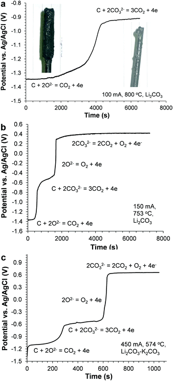 | ||
Fig. 41 Potential–time profiles of a mild steel working electrode (5 mm dia. rod) with electro-deposited carbon during anodic oxidation in molten salts under CO2. (a) Li2CO3 at 800 °C and 100 mA for 3600 s deposition at −2.1 V vs. Ag/AgCl (ca. 16![[thin space (1/6-em)]](https://www.rsc.org/images/entities/char_2009.gif) 000C in charge), (b) Li2CO3 at 753 °C and 150 mA for 600 s deposition at −2.1 V (ca.1200C), and (c) Li2CO3–K2CO3 (molar ratio: 62 000C in charge), (b) Li2CO3 at 753 °C and 150 mA for 600 s deposition at −2.1 V (ca.1200C), and (c) Li2CO3–K2CO3 (molar ratio: 62![[thin space (1/6-em)]](https://www.rsc.org/images/entities/char_2009.gif) : :![[thin space (1/6-em)]](https://www.rsc.org/images/entities/char_2009.gif) 38) at 574 °C for 600 s deposition at −2.6 V (ca. 850C). Photographs in (a) show the working electrode with the carbon deposit before (left) and after (right) anodic oxidation, respectively. Counter electrode: 10 mm dia. graphite rod.355 38) at 574 °C for 600 s deposition at −2.6 V (ca. 850C). Photographs in (a) show the working electrode with the carbon deposit before (left) and after (right) anodic oxidation, respectively. Counter electrode: 10 mm dia. graphite rod.355 | ||
6. Conclusions and outlook
In this review, we have introduced the recent progress in research and practice of various electrochemical energy storage (EES) devices from the perspective of electrolytes. The properties of typical examples of different types of electrolytes for EES devices are summarised in Table 2 to display both their advantages and limitations. These devices include the most recently developed secondary batteries, supercapacitors, supercapatteries, fuel cells, and redox flow batteries. Aqueous electrolytes were used in the very first battery in the world, and are still being widely used in various modern EES devices which require safety control and highly conductive electrolytes. Specifically, readers can also find the recent examples of aqueous electrolytes utilised in Li-ion and Na-ion batteries which usually use non-aqueous electrolytes. However, the limitation of the working voltage of the aqueous EES devices is still a drawback when high specific energy of the device is required in real applications. Organic electrolytes can offer a wider working potential window than aqueous electrolytes. Although the safety issue is still a barrier for organic electrolytes, they are widely used in the batteries of portable devices due to the high working voltage and high specific energy. Ionic liquids can offer acceptable conductivity and will not suffer from safety issues because of their inflammable and almost non-volatile nature. Recent studies on ionic liquid electrolytes also revealed their potential in EES devices. On the other hand, molten salts for EES devices are also introduced here. Both kinetic and thermodynamic barriers of the molten salt electrolyte based EES devices could be minimised, and hence a relatively high efficiency and high speed for energy conversion could be expected. In this review, we do not intend to downplay the importance of the electrode materials in all these EES devices. Actually in most cases, the typical electrode materials structures could affect the performance of the devices quite significantly. Here, we wish to emphasise the less discussed but important role of electrolytes in EES devices, and introduce some pioneering studies in which the electrolytes contribute greatly to the improvement of device performance.| Electrolyte | Typical example | Electrode materials | Conductivity, mS cm−1 | Cell voltage, V | Advantages | Limitations | Ref. |
|---|---|---|---|---|---|---|---|
| Aqueous electrolytes | 5 mol L−1 LiNO3 in water | (+) VO2(B)//LiMn2O4 (−) | ca. 103 | 1.5 | Non-combustible, affordability, high conductivity, low viscosity, non-toxic, low cost | Poor stability, self-discharge, narrower electrochemical window | 21 |
| 1 mol L−1 Li2SO4 aqueous electrolyte at pH = 13 in the absence of O2 | (+) LiTi2(PO4)3//LiFePO4 (−) | 0.9 | 22 | ||||
| 1 mol L−1 Na2SO4 in aqueous solution | (+) Hollow K0.27MnO2//NaTi2(PO4)3 (−) | 0.9 | 26 | ||||
| 1 mol L−1 KOH + 0.01 mol L−1 Zn(Ac)2 in aqueous solution | (+) Zn@CF//Co3O4@Ni (−) | 1.78 | 27 | ||||
| 0.2 mol L−1 HBr + 0.005 mol L−1 Br2 + 1.0 mol L−1 H2SO4 solution on the positive side and 0.05 mol L−1 AQDS + 1.0 mol L−1 H2SO4 solution on the negative side | (+) Photo-electrolysis cell//RFB (−) | 0.8 | 30 | ||||
| Organic electrolytes | 1.0 mol L−1 TMEABF4/AN | (+) AC//AC (−) | 50 | 3 | Wide electrochemical window, cyclability | Highly toxic, flammable, evaporation | 69 |
PYR14TFSI/PC (1![[thin space (1/6-em)]](https://www.rsc.org/images/entities/char_2009.gif) : :![[thin space (1/6-em)]](https://www.rsc.org/images/entities/char_2009.gif) 1 wt%) 1 wt%) |
10.3 | 3.5 | Low energy density | High conductivity | 74 | ||
| 0.7 mol L−1 Et4NBF4 in ADN | 4.3 | 3.75 | Wide electrochemical window | Low conductivity | 87 | ||
1.0 mol L−1 LiPF6 in EC + DMC (1![[thin space (1/6-em)]](https://www.rsc.org/images/entities/char_2009.gif) : :![[thin space (1/6-em)]](https://www.rsc.org/images/entities/char_2009.gif) 2, v/v) 2, v/v) |
(+) AC//LiNi0.5Mn1.5O4 (−) | ca. 10 | 2.0 | Cycle stability | Low working voltage | 93 | |
1.0 mol L−1 LiPF6 in EC + DMC (1![[thin space (1/6-em)]](https://www.rsc.org/images/entities/char_2009.gif) : :![[thin space (1/6-em)]](https://www.rsc.org/images/entities/char_2009.gif) 1, v/v) 1, v/v) |
(+) Graphite//AC (−) | 12 | 4.5 | Wide working voltage | Poor cycle stability | 110 | |
1.0 mol L−1 LiPF6 in EC + DMC (1![[thin space (1/6-em)]](https://www.rsc.org/images/entities/char_2009.gif) : :![[thin space (1/6-em)]](https://www.rsc.org/images/entities/char_2009.gif) 1, v/v) 1, v/v) |
(+) Graphite//LiCoO2 (−) | 12 | 4.0 | Excellent performance, low self-discharge, wide working voltage | Flammable, leakage | ||
1.0 mol L−1 LiPF6 in TMS + EMC (1![[thin space (1/6-em)]](https://www.rsc.org/images/entities/char_2009.gif) : :![[thin space (1/6-em)]](https://www.rsc.org/images/entities/char_2009.gif) 1, v/v) 1, v/v) |
(+) Li4Ti5O12//LiNi0.5Mn1.5O4 (−) | 5.1 | 3.2 | Nonflammable | Poor low temperature properties | 193 | |
1.0 mol L−1 LiPF6 in FEC + DMC + EMC + HFPM (2![[thin space (1/6-em)]](https://www.rsc.org/images/entities/char_2009.gif) : :![[thin space (1/6-em)]](https://www.rsc.org/images/entities/char_2009.gif) 3 3![[thin space (1/6-em)]](https://www.rsc.org/images/entities/char_2009.gif) : :![[thin space (1/6-em)]](https://www.rsc.org/images/entities/char_2009.gif) 1 1![[thin space (1/6-em)]](https://www.rsc.org/images/entities/char_2009.gif) : :![[thin space (1/6-em)]](https://www.rsc.org/images/entities/char_2009.gif) 4, v/v) 4, v/v) |
(+) MCMB//LiNi0.5Mn1.5O4 (−) | 8.57 | 4.6 | Nonflammable, good wettability, excellent cyclability | High cost, poor high-temperature performance | 198 | |
LiN(SO2F)2/DMA (1![[thin space (1/6-em)]](https://www.rsc.org/images/entities/char_2009.gif) : :![[thin space (1/6-em)]](https://www.rsc.org/images/entities/char_2009.gif) 1.1, molar ratio) 1.1, molar ratio) |
(+) Graphite//LiNi0.5Mn1.5O4 (−) | 1.12 | 5.2 | Superior thermal stability, flame retardant ability, effective inhibition of anodic Al dissolution | High viscosity, high cost, low conductivity | 222 | |
| 1.0 mol L−1 NaClO4 in EC0.45:PC0.45:DMC0.1 | (+) Hard C//Na3V2(PO4)2F3 (−) | 18 | 3.65 | High ionic conductivity, low viscosity, good rate capability, excellent capacity retention | Flammable | 264 | |
| 0.8 mol L−1 NaPF6/TMP + 10 vol% FEC | (+) Sb-based anode//NaNi0.35Mn0.35Fe0.3O2 (−) | 5.41 | 3.0 | Nonflammable | Low operation voltage | 273 | |
| 0.25 mol L−1 Mg(AlCl2BuEt)2 in THF | (+) Mg//MgxMo3S4 (−) | 1.0 to 1.4 | 1.1 | High energy density | Narrow electrochemical window, poor cyclability, low conductivity, high cost | 292 | |
| 0.75 mol L−1 Mg(CB11H12)2/tetraglyme (MMC/G4) electrolyte | (+) Mg//α-MnO2 (−) | 1.8 | 2.5 | 317 | |||
| Ionic liquid electrolytes | 0.5 mol L−1 LiClO4 in BMPyrrFAP + γ-GBL (1![[thin space (1/6-em)]](https://www.rsc.org/images/entities/char_2009.gif) : :![[thin space (1/6-em)]](https://www.rsc.org/images/entities/char_2009.gif) 1, v/v) 1, v/v) |
(+) Li//AC (−) | — | 4.3 | Wide electrochemical window, safety | Low conductivity, high cost, complicated synthesis, poor rate capability | 320 |
| Molten salt electrolytes | Molten NaAlCl4 + β-Al2O3 solid electrolyte | (+) Na//NiCl2 (−) | 36 | 2.58 | High ionic conductivity, high efficiency, ultrafast electrode charge-transfer kinetics, superior ion transport properties, remarkable long term stability | High operation temperature, degradation of the cell components | 323 |
Molten LiCl–LiF (30![[thin space (1/6-em)]](https://www.rsc.org/images/entities/char_2009.gif) : :![[thin space (1/6-em)]](https://www.rsc.org/images/entities/char_2009.gif) 70) 70) |
(+) Li//Bi (−) | — | 0.7 | 336 | |||
Li2CO3, Na2CO3 and K2CO3 (43.5![[thin space (1/6-em)]](https://www.rsc.org/images/entities/char_2009.gif) : :![[thin space (1/6-em)]](https://www.rsc.org/images/entities/char_2009.gif) 31.5 31.5![[thin space (1/6-em)]](https://www.rsc.org/images/entities/char_2009.gif) : :![[thin space (1/6-em)]](https://www.rsc.org/images/entities/char_2009.gif) 25 mol%) 25 mol%) |
(+) SnO2//Ni (−) | — | 1.8 | 353 | |||
We hope more attention will be paid to electrolyte studies to understand the mechanism of the interaction between the electrolytes and the electrode materials, and to improve the performance of the EES devices based on the existing mechanism. Further research needs to be done for electrolyte investigation and selection optimisation of different EES devices in order to obtain the desired cycling stability and safety. Since the interphases between electrodes and electrolytes directly affect the performance (affecting the energy capacity, rate performance, cyclability and safety) of EES devices, the fundamental understanding and control of the physical and chemical properties of these interphases are vital. The ideal interphase can only form upon well informed selection of solvents, salts and/or additives. Meanwhile, the development of in situ analytical tools to better characterise the composition distribution and properties of the interphase is also important for the design and optimisation of new and better electrolytes for application in different EES devices. A specific prospect can be related with the molten salt enabled electrochemical cycling between CO2 and carbon. Because solid carbon is a fuel and is stable in air, it is suitable for long term storage and long distance transportation. Therefore, we anticipate that the concepts of “seasonal energy storage” (SES) and “regional energy storage” (RES), as schematically illustrated in Fig. 42, can be tested and demonstrated. The purpose of SES is to store energy harvested in the sunny summer and reuse it in cold winter, whilst the RES aims to collect energy from remote desserts (sunlight to electricity) or mountains (wind to electricity) for use in urban areas. To achieve these goals, future research and development need to improve the process and energy efficiency of the electrochemical conversion between CO2 and carbon in molten salts. Obviously, continued research effort plays the key role in better understanding the mechanisms and kinetics of electrodeposition and re-oxidation of carbon for technological development. However, financial support, market establishment and public awareness are all equally important to make the process a commercial success.
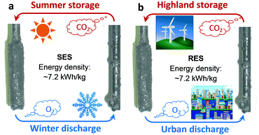 | ||
| Fig. 42 Schematic illustration of the concepts of (a) seasonal energy storage (SES) and (b) regional energy storage (RES) based on electrochemical cycling between carbon and CO2 in molten salts.353 | ||
List of abbreviations and acronyms
| 2,3BC | 2,3-Butylene carbonate |
| γ-GBL | Gamma-butyrolactone |
| Ac | Acetate |
| AC | Active carbon |
| ADN | Adiponitrile |
| AGG | Aggregate |
| AN | Acetonitrile |
| APC | All phenyl complex |
| AQDS | 9,10-Anthraquinone-2,7-disulphonic sodium |
| AQDSH2 | 1,8-Dihydroxy-9,10-anthraquinone-2,7-disulphonic sodium |
| BMPyrrFAP | 1-Butyl-1-methylpyrrolidinium tri(pentafluoroethyl)tri-fluorophosphate |
| CB11H12− | Monocarborane |
| CIP | Contact ion pair |
| CFs | Carbon fibres |
| CV | Cyclic voltammetry |
C![[double bond, length as m-dash]](https://www.rsc.org/images/entities/char_e001.gif) N N | Nitriles |
| [C3mPyr+][FSI−] | N-Propyl-N-methylpyrrolidinium bis(fluorosulfonyl)imide anion |
| DCC | Dichloro complexes |
| DCFCs | Direct carbon fuel cells |
| DES | Diethyl sulfite |
| DEC | Diethyl carbonate |
| DFEC | trans-Difluoroethylene carbonate |
| DMC | Dimethyl carbonate |
| DME | 1,2-Dimethoxyethane |
| DMSO | Dimethyl sulfoxide |
| DOL | 1,3-Dioxolane |
| EC | Ethylene carbonate |
| EDLCs | Electrical double-layer capacitors |
| EFPN | Ethoxy(pentafluoro)cyclotriphosphazene |
| EES | Electrochemical energy storage |
| EMIMBF4 | 1-Ethyl-3-methylimidazolium tetrafluoroborate |
| EMSF | Ethylmethyl sulfone |
| EMC | Ethyl methyl carbonate |
| EiPS | Ethyl isopropyl sulfone |
| ES | Ethylene sulfite |
| FAN | Fluoroacetonitrile |
| FEC | Fluoroethylene carbonate |
| G3 | Triglyme |
| G4 | Tetraglyme |
| GFMs | Glass fiber mats |
| GPEs | Gel polymer electrolytes |
| GLN | Glutaronitrile |
| HC | Hard carbon |
| HCEs | Highly concentrated electrolytes |
| HDI | Hexamethylenediisocyanate |
| HFPM | 1,1,1,3,3,3-Hexafluoroisopropyl methyl ether |
| HFiP | Tris(hexafluoro-iso-propyl)phosphate |
| HMDSMgCl | Hexamethyldisilazide magnesium chloride |
| HOMO | Highest occupied molecular orbital |
| LNMO | LiNi0.5Mn1.5O4 |
| LPTB | Lithium 4-pyridyl trimethyl borate |
| LiPF6 | Lithium hexafluorophosphate |
| LICs | Lithium ion capacitors |
| LIBs | Li-ion batteries |
| LiTFSI | LiN(SO2CF3)2 |
| LiTFSM | LiC(SO2CF3)3 |
| LiBOB | Lithium bis(oxalato)borate |
| LiDFOB | Lithium difluoro(oxalato)borate |
| LiBETI | LiN(SO2C2F5)2 |
| LiFSA | Lithium bis(fluorosulfonyl)imide |
| LiFSA | LiN(SO2F2)2 |
| MACC | Magnesium aluminium chloride complex |
| MCMB | Mesoporous carbon microbeads |
| MCFCs | Molten carbonate fuel cells |
| MD | Molecular dynamics |
| MEPYBF4 | 1-Ethyl-1-methyl-pyrrolidinium |
| Mes3B | Tri(3,5-dimethylphenyl)borane |
| MgB12H12 | closo-Borane magnesium dodecahydrododecaborate |
| NaTFSI | Sodium bis(trifluoromethane)sulfonamide |
| NaFTFSI | Sodium fluorosulfonyl(trifluoromethanesulfonyl)imide |
| NaFSI | Sodium bis(fluoro-sulfonyl)imide |
| NaOTf | NaSO3CF3 |
| NaTDI | Sodium 4,5-dicyano-2-(trifluoromethyl)imidazolate |
| NaPDI | Sodium 4,5-dicyano-2-(pentafluoroethyl)imidazolate |
| NaDFOB | Sodium difluoro-(oxalato)borate |
| Na@HC | Sodium inserted hard carbon |
| PACA | 1-Propylphosphonic acid cyclic anhydride |
| PAn | Polyaniline |
| PPy | Polypyrrole |
| PC | Propylene carbonate |
| PS | 1,3-Propylene sulfite |
| PEO | Poly(ethylene oxide) |
| PVDF | Poly(vinylidene fluoride) |
| PVDF–HFP | Poly(vinylidene difluoride-co-hexafluoropropylene) |
| PMMA | Poly(methyl methacrylate) |
| RFB | Redox flow battery |
| PFPN | (Ethoxy)pentafluorocyclotriphosphazene |
| PYR14TFSI | N-Butyl-N-methylpyrrolidinium bis(trifluoromethanesulfonyl)imide |
| PS | 1,3-Propane sultone |
| PCS | 1,3-Propanediol cyclic sulfate |
| PTSI | p-Toluenesulfonylisocyanate |
| SA | Succinic anhydride |
| SBP-BF4 | Spiro-(1,1′)-bipyrolidinium tetrafluoroborate |
| SLMP | Stabilized Li metal powder |
| SIBs | Sodium-ion batteries |
| SRFC | Solar rechargeable flow cell |
| TEMABF4 | Triethylmethylammonium |
| TEABF4 | Tetraethylammonium tetrafluoroborate |
| TFB | 1,3,5-Trifluorobenzene |
| TMPYBF4 | Tetramethylenepyrrolidinium |
| TMP | Trimethyl phosphite |
| TMSP | Tris(trimethylsilyl)phosphite |
| TMS | Tetramethylene sulfone |
| THF | Tetrahydrofuran |
| TiC-CDC | Titanium carbide derived carbon |
| VC | Vinylene carbonate |
| ZEBRA | Zero emissions batteries research activity |
Acknowledgements
This work received funding from the Ningbo Municipal Government (3315 Plan and the IAMET Special Fund, 2014A35001-1, and Ningbo Natural Science Foundation Programme, 2016A610114 and 2016A610115), the Zhejiang Provincial Applied Research Programme for Commonweal Technology (2016C31023 and 2017C31104), the NSFC (21503246), the EPSRC (EP/F026412/1 and EP/J000582/1) and the Royal Society (2007 Brian Mercer Feasibility Award).Notes and references
- M. Z. Jacobson, Energy Environ. Sci., 2009, 2, 148 CAS.
- M. He, F. Krzysztof, F. Elżbieta, N. Petr and J. B. Erik, Energy Environ. Sci., 2016, 9, 623 Search PubMed.
- Z. Yang, J. Zhang, M. C. W. Kintner-Meyer, X. Lu, D. Choi, J. P. Lemmon and J. Liu, Chem. Rev., 2011, 111, 3577 CrossRef CAS PubMed.
- M. M. Thackeray, C. Wolverton and E. D. Isaacs, Energy Environ. Sci., 2012, 5, 7854 CAS.
- J. B. Goodenough and K.-S. Park, J. Am. Chem. Soc., 2013, 135, 1167 CrossRef CAS PubMed.
- T.-H. Kim, J.-S. Park, S. K. Chang, S. Choi, J. H. Ryu and H.-K. Song, Adv. Energy Mater., 2012, 2, 860 CrossRef CAS.
- J. B. Goodenough and Y. Kim, Chem. Mater., 2010, 22, 587 CrossRef CAS.
- K. Kubota and S. Komaba, J. Electrochem. Soc., 2015, 162, A2538 CrossRef CAS.
- R. C. Massé, E. Uchaker and G. Cao, Sci. China Mater., 2015, 58, 715 CrossRef.
- K. Fic, L. Grzegorz, M. Mikolaj and F. Elzbieta, Energy Environ. Sci., 2012, 5, 5842 CAS.
- C. J. Wook and D. Aurbach, Nat. Rev. Mater., 2016, 1, 16013 CrossRef.
- Y. Orikasa, Sci. Rep., 2014, 4, 5622 CAS.
- S. S. Zhang and C. A. Angell, J. Electrochem. Soc., 1996, 143, 4047 CrossRef CAS.
- G. Ardar, A. E. S. Sleightholme, J. Naruse, H. Hiramatsu, D. J. Siegel and C. W. Monroe, ACS Appl. Mater. Interfaces, 2014, 6, 18033 Search PubMed.
- D. Monti, A. Ponrouch, M. R. Palacín and P. Johansson, J. Power Sources, 2016, 324, 712 CrossRef CAS.
- P. G. Bruce, S. A. Freunberger, L. J. Hardwick and J.-M. Tarascon, Nat. Mater., 2012, 11, 19 CrossRef CAS PubMed.
- A. C. Kozen, ACS Nano, 2015, 9, 5884 CrossRef CAS PubMed.
- A. Balducci, B. Ugo, C. Stefano, M. Marina and S. Francesca, Electrochem. Commun., 2004, 6, 566 CrossRef CAS.
- D. Aurbach, Electrochim. Acta, 2004, 50, 247 CrossRef CAS.
- V. Palomares, S. Paula, V. Irune, B. H. Karina, C.-G. Javier and R. Teófilo, Energy Environ. Sci., 2012, 5, 5884 CAS.
- W. Li, J. R. Dahn and D. S. Wainwright, Science, 1994, 264, 1115 CAS.
- J.-Y. Luo, W.-J. Cui, P. He and Y.-Y. Xia, Nat. Chem., 2010, 2, 760 CrossRef CAS PubMed.
- Z. Chang, C. Li, Y. Wang, B. Chen, L. Fu, Y. Zhu, L. Zhang, Y. Wu and W. Huang, Sci. Rep., 2016, 6, 28421 CrossRef CAS PubMed.
- X. Wang, Y. Hou, Y. Zhu, Y. Wu and R. Holze, Sci. Rep., 2013, 3, 1401 Search PubMed.
- Z. Chang, Y. Yang, X. Wang, M. Li, Z. Fu, Y. Wu and R. Holze, Sci. Rep., 2015, 5, 11931 CrossRef CAS PubMed.
- Y. Liu, Y. Qiao, X. Lou, X. Zhang, W. Zhang and Y. Huang, ACS Appl. Mater. Interfaces, 2016, 8, 14564 Search PubMed.
- X. Wang, F. Wang, L. Wang, M. Li, Y. Wang, B. Chen, Y. Zhu, L. Fu, L. Zha, L. Zhang, Y. Wu and W. Huang, Adv. Mater., 2016, 28, 4904 CrossRef CAS PubMed.
- P. Leung, X. Li, C. Ponce de Leon, L. Berlouis, C. T. J. Low and F. C. Walsh, RSC Adv., 2012, 2, 10125 RSC.
- P. Zhao, H. Zhang, H. Zhou, J. Chen, S. Gao and B. Yi, J. Power Sources, 2006, 162, 1416 CrossRef CAS.
- S. Liao, X. Zong, B. Seger, T. Pedersen, T. Yao, C. Ding, J. Shi, J. Chen and C. Li, Nat. Commun., 2016, 7, 11474 CrossRef CAS PubMed.
- M. Wu, G. A. Snook, V. Gupta, M. Shaffer, D. J. Fray and G. Z. Chen, J. Mater. Chem., 2005, 15, 2297 RSC.
- C. Peng, J. Jin and G. Z. Chen, Electrochim. Acta, 2007, 53, 525 CrossRef CAS.
- C. Peng, S. Zhang, X. Zhou and G. Z. Chen, Energy Environ. Sci., 2010, 3, 1499 Search PubMed.
- G. Z. Chen, M. S. P. Shaffer, D. Coleby, G. Dixon, W. Zhou and D. J. Fray, Adv. Mater., 2000, 12, 522 CrossRef CAS.
- M. Hughes, G. Z. Chen, M. S. P. Shaffer, D. J. Fray and A. H. Windle, Chem. Mater., 2002, 14, 1610 CrossRef CAS.
- G. A. Snook, G. Z. Chen, D. J. Fray, M. Hughes and M. Shaffer, J. Electroanal. Chem., 2004, 568, 135 CrossRef CAS.
- X. Zhou, C. Peng and G. Z. Chen, AIChE J., 2012, 58, 974 CrossRef CAS.
- A. P. Malloy and S. W. Donne, J. Power Sources, 2008, 179, 371 CrossRef CAS.
- Y. D. Qu, B. E. Conway, L. Bai, Y. H. Zhou and W. A. Adams, J. Appl. Electrochem., 1993, 23, 693 CrossRef.
- A. Kozawa, T. Kalnoki-Kis and J. F. Yeager, J. Electrochem. Soc., 1966, 113, 405 CrossRef CAS.
- F. X. Wang, S. Y. Xiao, Y. S. Zhu, Z. Chang, C. L. Hu, Y. P. Wu and R. Holze, J. Power Sources, 2014, 246, 19 CrossRef CAS.
- R. T. Vinny, K. Chaitra, K. Venkatesh, N. Nagaraju and N. Kathyayini, J. Power Sources, 2016, 309, 212 CrossRef CAS.
- Q. Qu, L. Li, S. Tian, W. Guo, Y. Wu and R. Holze, J. Power Sources, 2010, 195, 2789 CrossRef CAS.
- X. Jin, W. Zhou, S. Zhang and G. Z. Chen, Small, 2007, 3, 1513 CrossRef CAS PubMed.
- Y. U. Jeong and A. Manthiram, J. Electrochem. Soc., 2002, 149, A1419 CrossRef CAS.
- D. W. Kirt and J. W. Graydon, ECS Trans., 2010, 25, 163 Search PubMed.
- Y. Gao, Z. Qin, L. Guan, X. Wang and G. Z. Chen, Chem. Commun., 2015, 51, 10819 RSC.
- B. Dunn, H. Kamath and J. M. Tarascon, Science, 2011, 334, 928 CrossRef CAS PubMed.
- Y. Si and E. T. Samulski, Nano Lett., 2008, 8, 1679 CrossRef CAS PubMed.
- D. Li, M. B. Muller, S. Gilje, R. B. Kaner and G. G. Wallace, Nat. Nanotechnol., 2008, 3, 101 CrossRef CAS PubMed.
- A. Lewandowski, A. Olejniczak, M. Galinsk and I. Stepniak, J. Power Sources, 2010, 195, 5814 CrossRef CAS.
- F. Beguin, V. Presser, A. Balducci and E. Frackowiak, Adv. Mater., 2014, 26, 2219 CrossRef CAS PubMed.
- C. Zhong, Y. Deng, W. Hu, J. Qiao, L. Zhang and J. Zhang, Chem. Soc. Rev., 2015, 44, 7484 RSC.
- E. Iwama, P. L. Taberna, P. Azais, L. Brégeon and P. Simon, J. Power Sources, 2012, 219, 235 CrossRef CAS.
- D. E. Jiang, Z. Jin, D. Henderson and J. Wu, J. Phys. Chem. Lett., 2012, 3, 1727 CrossRef CAS PubMed.
- P. Liu, M. Verbrugge and S. Soukiazian, J. Power Sources, 2006, 156, 712 CrossRef CAS.
- M. S. Erik Brandon, William West, NASA Tech. Briefs, 2010, vol. 34, p. 21.
- M. Ue, J. Electrochem. Soc., 1994, 141, 3336 CrossRef CAS.
- M. Ue, K. Ida and S. Mori, J. Electrochem. Soc., 1994, 141, 2989 CrossRef CAS.
- M. Ue, Electrochim. Acta, 1994, 39, 2083 CrossRef CAS.
- M. Ue, M. Takeda, M. Takehara and S. Mori, J. Electrochem. Soc., 1997, 144, 2684 CrossRef CAS.
- S. Mori, K. Ida and M. Ue, US Pat., 4892944, 1990 Search PubMed.
- M. Ue, Electrochemistry, 2007, 75, 565 CrossRef CAS.
- M. Ue, M. Takehara, Y. Oura, A. Toriumi, M. Takeda and D. Kagaku, Electrochemistry, 2001, 69, 458 CAS.
- M. Ue, M. Takehara, M. Takeda and D. Kagaku, Electrochemistry, 1997, 65, 969 CAS.
- K. Chiba, US Pat., US 20060274475 A1, 2008 Search PubMed.
- P. Simon and Y. Gogotsi, Nat. Mater., 2008, 7, 845 CrossRef CAS PubMed.
- P. Kurzweil and M. Chwistek, J. Power Sources, 2008, 176, 555 CrossRef CAS.
- A. R. Koh, B. Hwang, K. C. Roh and K. Kim, Phys. Chem. Chem. Phys., 2014, 16, 15146 RSC.
- A. Jänes, H. Kurig, T. Romann and E. Lust, Electrochem. Commun., 2010, 12, 535 CrossRef.
- Y. Yokoyama, N. Shimosaka, H. Matsumoto, M. Yoshio and T. Ishiharaa, Electrochem. Solid-State Lett., 2008, 11, A72 CrossRef CAS.
- K. Xu, M. S. Ding and T. R. Jow, J. Electrochem. Soc., 2001, 148, A267 CrossRef CAS.
- H. Kurig, A. Janes and E. Lust, J. Mater. Res., 2010, 25, 1447 CrossRef CAS.
- A. Krause and A. Balducci, Electrochem. Commun., 2011, 13, 814 CrossRef CAS.
- S. Pohlmann and A. Balducci, Electrochim. Acta, 2013, 110, 221 CrossRef CAS.
- X. Yu, D. Ruan, C. Wu, J. Wang and Z. Shi, J. Power Sources, 2014, 265, 309 CrossRef CAS.
- C. Hu, W. Qu, R. Rajagopalan and C. Randall, J. Power Sources, 2014, 272, 90 CrossRef CAS.
- K. Naoi, S. Ishimoto, J.-i. Miyamoto and W. Naoi, Energy Environ. Sci., 2012, 5, 9363 CAS.
- L. He, J. Li, F. Gao, X. Wang, F. Ye and J. Yang, Electrochemistry, 2011, 79, 934 CrossRef CAS.
- P. W. Ruch, D. Cericola, A. Foelske-Schmitz, R. Kötz and A. Wokaun, Electrochim. Acta, 2010, 55, 4412 CrossRef CAS.
- S. Ishimoto, Y. Asakawa, M. Shinya and K. Naoi, J. Electrochem. Soc., 2009, 156, A563 CrossRef CAS.
- M. Hahn, A. Würsig, R. Gallay, P. Novák and R. Kötz, Electrochem. Commun., 2005, 7, 925 CrossRef CAS.
- K. Chiba, T. Ueda, Y. Yamaguchi, Y. Oki, F. Shimodate and K. Naoi, J. Electrochem. Soc., 2011, 158, A872 CrossRef CAS.
- K. Chiba, T. Ueda, Y. Yamaguchi, Y. Oki, F. Saiki and K. Naoi, J. Electrochem. Soc., 2011, 158, A1320 CrossRef CAS.
- R. Francke, D. Cericola, R. Kötz, D. Weingarth and S. R. Waldvogel, Electrochim. Acta, 2012, 62, 372 CrossRef CAS.
- K. Suzuki, M. Shin-Ya, Y. Ono, T. Matsumoto, N. Nanbu, M. Takehara, M. Ue and Y. Sasaki, Electrochemistry, 2007, 75, 611 CrossRef CAS.
- A. Brandt, P. Isken, A. Lex-Balducci and A. Balducci, J. Power Sources, 2012, 204, 213 CrossRef CAS.
- K. Naoi, Fuel Cells, 2010, 10, 825 CrossRef CAS.
- A. Du Pasquier, I. Plitz, S. Menocal and G. Amatucci, J. Power Sources, 2003, 115, 171 CrossRef CAS.
- D. Cericola, P. Novák, A. Wokaun and R. Kötz, J. Power Sources, 2011, 196, 10305 CrossRef CAS.
- A. Krause, P. Kossyrev, M. Oljaca, S. Passerini, M. Winter and A. Balducci, J. Power Sources, 2011, 196, 8836 CrossRef CAS.
- S. Liu, S. Liu, K. Huang, J. Liu, Y. Li, D. Fang, H. Wang and Y. Xia, J. Solid State Electrochem., 2011, 16, 1631 CrossRef.
- H. Li, L. Cheng and Y. Xia, Electrochem. Solid-State Lett., 2005, 8, A433 CrossRef CAS.
- H. Wu, C. V. Rao and B. Rambabu, Mater. Chem. Phys., 2009, 116, 532 CrossRef CAS.
- A. Brandt, A. Balducci, U. Rodehorst, S. Menne, M. Winter and A. Bhaskar, J. Electrochem. Soc., 2014, 161, A1139 CrossRef CAS.
- H. Wang and M. Yoshio, Electrochem. Commun., 2006, 8, 1481 CrossRef CAS.
- H. Wang, M. Yoshio, A. K. Thapa and H. Nakamura, J. Power Sources, 2007, 169, 375 CrossRef CAS.
- H. Wang and M. Yoshio, Electrochem. Commun., 2008, 10, 382 CrossRef CAS.
- Y. Wang, C. Zheng, L. Qi, M. Yoshio, K. Yoshizuka and H. Wang, J. Power Sources, 2011, 196, 10507 CrossRef CAS.
- J. Gao, S. Tian, L. Qi and H. Wang, Electrochim. Acta, 2015, 176, 22 CrossRef CAS.
- J. Gao, S. Tian, L. Qi, M. Yoshio and H. Wang, J. Power Sources, 2015, 297, 121 CrossRef CAS.
- J. Gao, M. Yoshio, L. Qi and H. Wang, J. Power Sources, 2015, 278, 452 CrossRef CAS.
- H. Wang and M. Yoshio, J. Power Sources, 2008, 177, 681 CrossRef CAS.
- T. Aida, K. Yamada and M. Morita, Electrochem. Solid-State Lett., 2006, 9, A534 CrossRef CAS.
- W. J. Cao and J. P. Zheng, J. Power Sources, 2012, 213, 180 CrossRef CAS.
- N. Ogihara, Y. Igarashi, A. Kamakura, K. Naoi, Y. Kusachi and K. Utsugi, Electrochim. Acta, 2006, 52, 1713 CrossRef CAS.
- S. R. Sivakkumar, J. Y. Nerkar and A. G. Pandolfo, Electrochim. Acta, 2010, 55, 3330 CrossRef CAS.
- S. R. Sivakkumar and A. G. Pandolfo, Electrochim. Acta, 2012, 65, 280 CrossRef CAS.
- S. R. Sivakkumar, A. S. Milev and A. G. Pandolfo, Electrochim. Acta, 2011, 56, 9700 CrossRef CAS.
- V. Khomenko, E. Raymundo-Piñero and F. Béguin, J. Power Sources, 2008, 177, 643 CrossRef CAS.
- M. Schroeder, M. Winter, S. Passerini and A. Balducci, J. Electrochem. Soc., 2012, 159, A1240 CrossRef CAS.
- T. Aida, I. Murayama, K. Yamada and M. Morita, Electrochem. Solid-State Lett., 2007, 10, A93 CrossRef CAS.
- T. Aida, I. Murayama, K. Yamada and M. Morita, J. Electrochem. Soc., 2007, 154, A798 CrossRef CAS.
- W. J. Cao and J. P. Zheng, J. Electrochem. Soc., 2013, 160, A1572 CrossRef CAS.
- H. Wang and M. Yoshio, J. Power Sources, 2012, 200, 108 CrossRef CAS.
- P. H. Smith, T. N. Tran, T. L. Jiang and J. Chung, J. Power Sources, 2013, 243, 982 CrossRef CAS.
- A. Jänes, J. Eskusson, T. Thomberg and E. Lust, J. Electrochem. Soc., 2014, 161, A1284 CrossRef.
- J. Eskusson, A. Jänes, T. Thomberg and E. Lust, ECS Trans., 2015, 64, 21 CrossRef CAS.
- J. C. Burns, A. Kassam, N. N. Sinha, L. E. Downie, L. Solnickova, B. M. Way and J. R. Dahn, J. Electrochem. Soc., 2013, 160, A1451 CrossRef CAS.
- G. H. Wrodnigg, T. M. Wrodnigg, J. O. Besenhard and M. Winter, Electrochem. Commun., 1999, 1, 148 CrossRef CAS.
- H. W. Jung, L. Hamenu, H. S. Lee, M. Latifatu, K. M. Kim and J. M. Ko, Curr. Appl. Phys., 2015, 15, 567 CrossRef.
- C. H. Lee, F. Xu and C. Jung, Electrochim. Acta, 2014, 131, 240 CrossRef CAS.
- W. Qu, E. Dorjpalam, R. Rajagopalan and C. A. Randall, ChemSusChem, 2014, 7, 1162 CrossRef CAS PubMed.
- D. Aurbach, J. Power Sources, 2000, 89, 206–218 CrossRef CAS.
- P. G. Balakrishnan, R. Ramesh and T. Prem Kumar, J. Power Sources, 2006, 155, 401 CrossRef CAS.
- V. Etacheri, R. Marom, R. Elazari, G. Salitra and D. Aurbach, Energy Environ. Sci., 2011, 4, 3243 CAS.
- K. Xu, Chem. Rev., 2014, 114, 11503 CrossRef CAS PubMed.
- K. Xu, Chem. Rev., 2004, 104, 4303 CrossRef CAS PubMed.
- E. M. Erickson, E. Markevich, G. Salitra, D. Sharon, D. Hirshberg, E. de la Llave, I. Shterenberg, A. Rozenman, A. Frimer and D. Aurbach, J. Electrochem. Soc., 2015, 162, A2424 CrossRef CAS.
- D. Guyomard and J. M. Tarascon, J. Electrochem. Soc., 1992, 139, 937 CrossRef CAS.
- J. M. Tarascon, D. Guyomard and G. L. Baker, J. Power Sources, 1993, 43–44, 689 CrossRef.
- D. Guyomard and J. M. Tarascon, J. Power Sources, 1995, 54, 92 CrossRef CAS.
- J. M. Tarascon and D. Guyomard, Electrochim. Acta, 1993, 38, 1221 CrossRef CAS.
- J. O. Besenhard, M. Winter, J. Yang and W. Biberacher, J. Power Sources, 1995, 54, 228 CrossRef CAS.
- A. M. Andersson, D. P. Abraham, R. Haasch, S. MacLaren, J. Liu and K. Amine, J. Electrochem. Soc., 2002, 149, A1358 CrossRef CAS.
- D. Aurbach, B. Markovsky, A. Shechter, Y. Ein-Eli and H. Cohen, J. Electrochem. Soc., 1996, 143, 3809 CrossRef CAS.
- D. Aurbach, Y. Talyosef, B. Markovsky, E. Markevich, E. Zinigrad, L. Asraf, J. S. Gnanaraj and H. J. Kim, Electrochim. Acta, 2004, 50, 247 CrossRef CAS.
- B. Markovsky, F. Amalraj, H. E. Gottlieb, Y. Gofer, S. K. Martha and D. Aurbach, J. Electrochem. Soc., 2010, 157, A423 CrossRef CAS.
- E. Sloop, J. K. Pugh, S. Wang, J. B. Kerr and K. Kinoshita, Electrochem. Solid-State Lett., 2001, 4, 42 CrossRef.
- D. Aurbach, K. Gamolsky, B. Markovsky, G. Salitra and Y. Gofer, J. Electrochem. Soc., 2000, 147, 1322 CrossRef CAS.
- J. Foropoulos and D. D. DesMarteau, Inorg. Chem., 1984, 23, 3720 CrossRef CAS.
- L. Péter and J. Arai, J. Appl. Electrochem., 1999, 29, 1053 CrossRef.
- L. A. Dominey, V. R. Koch and T. J. Blakley, Electrochim. Acta, 1992, 37, 1551 CrossRef CAS.
- M. Ue, A. Murakami and S. Nakamura, J. Electrochem. Soc., 2002, 149, A1572 CrossRef CAS.
- K. Kanamura, W. Hoshikawa and T. Umegaki, J. Electrochem. Soc., 2002, 149, 339 CrossRef.
- A. M. Haregewoin, A. S. Wotango and B. J. Hwang, Energy Environ. Sci., 2016, 9, 1955 CAS.
- M. Hu, X. Pang and Z. Zhou, J. Power Sources, 2013, 237, 229 CrossRef CAS.
- W. Liu, Angew. Chem., Int. Ed., 2015, 54, 4440 CrossRef CAS PubMed.
- S. Hy, H. Liu, M. Zhang, D. Qian, B.-J. Hwang and Y. S. Meng, Energy Environ. Sci., 2016, 9, 1931 CAS.
- A. Vanchiappan, J. Gnanaraj, S. Madhavi and H.-K. Liu, Chem. – Eur. J., 2011, 17, 14326 CrossRef PubMed.
- M. Xu, S. Dalavi and B. L. Lucht, Electrolytes for Lithium-Ion Batteries with High-Voltage Cathodes [B], Lithium Batteries, 2013, 71 Search PubMed.
- L. Yang, B. Ravdel and B. L. Lucht, Electrochem. Solid-State Lett., 2010, 13, A95 CrossRef CAS.
- L. Xing, W. Li, C. Wang, F. Gu, M. Xu, C. Tan and J. Yi, J. Phys. Chem. B, 2009, 113, 16596 CrossRef CAS PubMed.
- J.-H. Kim, N. P. W. Pieczonka, Z. Li, Y. Wu, S. Harris and B. R. Powell, Electrochim. Acta, 2013, 90, 556 CrossRef CAS.
- N. P. W. Pieczonka, Z. Liu, P. Lu, K. L. Olson, J. Moote, B. R. Powell and J.-H. Kim, J. Phys. Chem. C, 2013, 117, 15947 CAS.
- S. Dalavi, M. Xu, B. Knight and B. L. Lucht, Electrochem. Solid-State Lett., 2011, 15, A28 CrossRef.
- L. Yang, T. Markmaitree and B. L. Lucht, J. Power Sources, 2011, 196, 2251 CrossRef CAS.
- S.-Y. Ha, J.-G. Han, Y.-M. Song, M.-J. Chun, S.-I. Han, W.-C. Shin and N.-S. Choi, Electrochim. Acta, 2013, 104, 170 CrossRef CAS.
- M. Hu, J. Wei, L. Xing and Z. Zhou, J. Appl. Electrochem., 2012, 42, 291 CrossRef CAS.
- Z. D. Li, Y. C. Zhang, H. F. Xiang, X. H. Ma, Q. F. Yuan, Q. S. Wang and C. H. Chen, J. Power Sources, 2013, 240, 471 CrossRef CAS.
- A. von Cresce and K. Xu, J. Electrochem. Soc., 2011, 158, A337 CrossRef CAS.
- A. Von Cresce and K. Xu, ECS Trans., 2012, 41, 17 CAS.
- H. Rong, M. Xu, L. Xing and W. Li, J. Power Sources, 2014, 261, 148 CrossRef CAS.
- Y.-M. Song, J.-G. Han, S. Park, K. T. Lee and N.-S. Choi, J. Mater. Chem. A, 2014, 2, 9506 CAS.
- G. Yan, X. Li, Z. Wang, H. Guo and C. Wang, J. Power Sources, 2014, 248, 1306 CrossRef CAS.
- J. Zhang, J. Wang, J. Yang and Y. NuLi, Electrochim. Acta, 2014, 117, 99 CrossRef CAS.
- L. Xia, Y. Xia and Z. Liu, J. Power Sources, 2015, 278, 190 CrossRef CAS.
- G. Yan, X. Li, Z. Wang, H. Guo and X. Xiong, J. Power Sources, 2014, 263, 231 CrossRef CAS.
- H. Lee, S. Choi, S. Choi, H.-J. Kim, Y. Choi, S. Yoon and J.-J. Cho, Electrochem. Commun., 2007, 9, 801 CrossRef CAS.
- F. Felix, J.-H. Cheng, S. Hy, J. Rick, F. M. Wang and B.-J. Hwang, J. Phys. Chem. C, 2013, 22619 Search PubMed.
- V. Tarnopolskiy, J. Kalhoff, M. Nádherná, D. Bresser, L. Picard, F. Fabre, M. Rey and S. Passerini, J. Power Sources, 2013, 236, 39 CrossRef CAS.
- H. Bouayad, Z. Wang, N. Dupré, R. Dedryvère, D. Foix, S. Franger, J.-F. Martin, L. Boutafa, S. Patoux, D. Gonbeau and D. Guyomard, J. Phys. Chem. C, 2014, 118, 4634 CAS.
- N. P. W. Pieczonka, L. Yang, M. P. Balogh, B. R. Powell, K. R. Chemelewski, A. Manthiram, S. A. Krachkovskiy, G. R. Goward, M. Liu and J.-H. Kim, J. Phys. Chem. C, 2013, 117, 22603 CAS.
- K. Xu, S. Zhang and T. R. Jow, Electrochem. Solid-State Lett., 2003, 6, A117 CrossRef CAS.
- Q. Wu, W. Lu, M. Miranda, T. K. Honaker-Schroeder, K. Y. Lakhsassi and D. Dees, Electrochem. Commun., 2012, 24, 78 CrossRef CAS.
- M. Xu, L. Zhou, Y. Dong, Y. Chen, J. Demeaux, A. D. MacIntosh, A. Garsuch and B. L. Lucht, Energy Environ. Sci., 2016, 9, 1308 CAS.
- E. Nanini-Maury, J. Światowska, A. Chagnes, S. Zanna, P. Tran-Van, P. Marcus and M. Cassir, Electrochim. Acta, 2014, 115, 223 CrossRef CAS.
- M. Nagahama, N. Hasegawa and S. Okada, J. Electrochem. Soc., 2010, 157, A748 CrossRef CAS.
- L. Kavan, Chem. Rev., 1997, 97, 3061 CrossRef CAS PubMed.
- Y. Abu-Lebdeh and I. Davidson, J. Electrochem. Soc., 2009, 156, A60 CrossRef CAS.
- Y. Abu-Lebdeh and I. Davidson, J. Power Sources, 2009, 189, 576 CrossRef CAS.
- A. J. Gmitter, I. Plitz and G. G. Amatucci, J. Electrochem. Soc., 2012, 159, A370 CrossRef CAS.
- K. Xu and C. A. Angell, J. Electrochem. Soc., 1998, 145, L70 CrossRef CAS.
- X.-G. Sun and C. Austen Angell, Solid State Ionics, 2004, 175, 257 CrossRef CAS.
- X.-G. Sun and C. A. Angell, Electrochem. Commun., 2005, 7, 261 CrossRef CAS.
- X. Sun and C. A. Angell, Meeting Abstracts, 2008, MA2008-01, 1417.
- Y. Watanabe, S.-i. Kinoshita, S. Wada, K. Hoshino, H. Morimoto and S.-i. Tobishima, J. Power Sources, 2008, 179, 770 CrossRef CAS.
- X. Sun and C. A. Angell, Electrochem. Commun., 2009, 11, 1418 CrossRef CAS.
- L. Mao, B. Li, X. Cui, Y. Zhao, X. Xu, X. Shi, S. Li and F. Li, Electrochim. Acta, 2012, 79, 197 CrossRef CAS.
- C. Li, Y. Zhao, H. Zhang, J. Liu, J. Jing, X. Cui and S. Li, Electrochim. Acta, 2013, 104, 134 CrossRef CAS.
- F. Wu, J. Xiang, L. Li, J. Chen, G. Tan and R. Chen, J. Power Sources, 2012, 202, 322 CrossRef CAS.
- F. Wu, Q. Zhu, L. Li, R. Chen and S. Chen, J. Mater. Chem. A, 2013, 1, 3659–3666 CAS.
- A. Abouimrane, I. Belharouak and K. Amine, Electrochem. Commun., 2009, 11, 1073 CrossRef CAS.
- L. Xing, J. Vatamanu, O. Borodin, G. D. Smith and D. Bedrov, J. Phys. Chem. C, 2012, 116, 23871 CAS.
- T. Kitagawa, K. Azuma, M. Koh, A. Yamauchi, M. Kagawa, H. Sakata, H. Miyawaki, A. Nakazono, H. Arima and M. Yamagata, Electrochemistry, 2010, 78, 345 CrossRef CAS.
- L. Hu, Z. Zhang and K. Amine, Electrochem. Commun., 2013, 35, 76 CrossRef CAS.
- Z. Zhang, L. Hu, H. Wu, W. Weng, M. Koh, P. C. Redfern, L. A. Curtiss and K. Amine, Energy Environ. Sci., 2013, 6, 1806 CAS.
- L. Xia, Y. Xia, C. Wang, H. Hu, S. Lee, Q. Yu, H. Chen and Z. Liu, ChemElectroChem, 2015, 2, 1707 CrossRef CAS.
- M. Ue, K. Ida and S. Mori, J. Electrochem. Soc., 1994, 141, 2989 CrossRef CAS.
- X. Zhang, R.-S. Kühnel, S. Passerini and A. Balducci, J. Solution Chem., 2015, 44, 528 CrossRef CAS.
- N. Shao, X.-G. Sun, S. Dai and D.-e. Jiang, J. Phys. Chem. B, 2011, 115, 12120 CrossRef CAS PubMed.
- N. Shao, X.-G. Sun, S. Dai and D.-e. Jiang, J. Phys. Chem. B, 2012, 116, 3235 CrossRef CAS PubMed.
- D. Kobayashi, M. Takehara, N. Nanbu, M. Ue and Y. Sasaki, Meeting Abstracts, 2008, MA2008-02, 166.
- Y. Sasaki, H. Satake, N. Tsukimori, N. Nanbu, M. Takehara and M. Ue, Electrochemistry, 2010, 78, 467 CrossRef CAS.
- E. Markevich, G. Salitra, K. Fridman, R. Sharabi, G. Gershinsky, A. Garsuch, G. Semrau, M. A. Schmidt and D. Aurbach, Langmuir, 2014, 30, 7414 CrossRef CAS PubMed.
- Y. Yamada and A. Yamada, J. Electrochem. Soc., 2015, 162, A2406 CrossRef CAS.
- Y. Yamada, K. Furukawa, K. Sodeyama, K. Kikuchi, M. Yaegashi, Y. Tateyama and A. Yamada, J. Am. Chem. Soc., 2014, 136, 5039 CrossRef CAS PubMed.
- S.-K. Jeong, H.-Y. Seo, D.-H. Kim, H.-K. Han, J.-G. Kim, Y. B. Lee, Y. Iriyama, T. Abe and Z. Ogumi, Electrochem. Commun., 2008, 10, 635 CrossRef CAS.
- L. Suo, Y.-S. Hu, H. Li, M. Armand and L. Chen, Nat. Commun., 2013, 4, 1481 CrossRef PubMed.
- J. Qian, W. A. Henderson, W. Xu, P. Bhattacharya, M. Engelhard, O. Borodin and J. G. Zhang, Nat. Commun., 2015, 6, 6362 CrossRef CAS PubMed.
- Q. Ma, Z. Fang, P. Liu, J. Ma, X. Qi, W. Feng, J. Nie, Y.-S. Hu, H. Li, X. Huang, L. Chen and Z. Zhou, ChemElectroChem, 2016, 3, 531 CrossRef CAS.
- J. O. Besenhard, Carbon, 1976, 14, 111 CrossRef CAS.
- G. Nagasubramanian, J. Power Sources, 2003, 119–121, 811 CrossRef CAS.
- M. Arakawa and J. Yamaki, J. Electroanal. Chem., 1987, 219, 273 CrossRef CAS.
- T. Abe, N. Kawabata, Y. Mizutani, M. Inaba and Z. Ogumi, J. Electrochem. Soc., 2003, 150, A257 CrossRef CAS.
- M. Nie, D. P. Abraham, D. M. Seo, Y. Chen, A. Bose and B. L. Lucht, J. Phys. Chem. C, 2013, 117, 25381 CAS.
- Y. Yamada, Y. Takazawa, K. Miyazaki and T. Abe, J. Phys. Chem. C, 2010, 114, 11680 CAS.
- Y. Yamada, M. Yaegashi, T. Abe and A. Yamada, Chem. Commun., 2013, 49, 11194 RSC.
- Y. Yamada, K. Usui, C. H. Chiang, K. Kikuchi, K. Furukawa and A. Yamada, ACS Appl. Mater. Interfaces, 2014, 6, 10892 CAS.
- K. Sodeyama, Y. Yamada, K. Aikawa, A. Yamada and Y. Tateyama, J. Phys. Chem. C, 2014, 118, 14091 CAS.
- T. Doi, R. Masuhara, M. Hashinokuchi, Y. Shimizu and M. Inaba, Electrochim. Acta, 2016, 209, 219 CrossRef CAS.
- J. Wang, Y. Yamada, K. Sodeyama, C. H. Chiang, Y. Tateyama and A. Yamada, Nat. Commun., 2016, 7, 12032 CrossRef CAS PubMed.
- K. Matsumoto, K. Inoue, K. Nakahara, R. Yuge, T. Noguchi and K. Utsugi, J. Power Sources, 2013, 231, 234 CrossRef CAS.
- D. W. McOwen, D. M. Seo, O. Borodin, J. Vatamanu, P. D. Boyle and W. A. Henderson, Energy Environ. Sci., 2014, 7, 416 CAS.
- Y. Yamada, C. H. Chiang, K. Sodeyama, J. Wang, Y. Tateyama and A. Yamada, ChemElectroChem, 2015, 2, 1687 CrossRef CAS.
- K. Dokko, N. Tachikawa, K. Yamauchi, M. Tsuchiya, A. Yamazaki, E. Takashima, J.-W. Park, K. Ueno, S. Seki, N. Serizawa and M. Watanabe, J. Electrochem. Soc., 2013, 160, A1304 CrossRef CAS.
- K. Yoshida, M. Nakamura, Y. Kazue, N. Tachikawa, S. Tsuzuki, S. Seki, K. Dokko and M. Watanabe, J. Am. Chem. Soc., 2011, 133, 13121 CrossRef CAS PubMed.
- J.-W. Park, K. Yamauchi, E. Takashima, N. Tachikawa, K. Ueno, K. Dokko and M. Watanabe, J. Phys. Chem. C, 2013, 117, 4431 CAS.
- C. Zhang, A. Yamazaki, J. Murai, J.-W. Park, T. Mandai, K. Ueno, K. Dokko and M. Watanabe, J. Phys. Chem. C, 2014, 118, 17362 CAS.
- H. Moon, R. Tatara, T. Mandai, K. Ueno, K. Yoshida, N. Tachikawa, T. Yasuda, K. Dokko and M. Watanabe, J. Phys. Chem. C, 2014, 118, 20246 CAS.
- K. Ueno, K. Yoshida, M. Tsuchiya, N. Tachikawa, K. Dokko and M. Watanabe, J. Phys. Chem. B, 2012, 116, 11323 CrossRef CAS PubMed.
- K. Ueno, J. Murai, K. Ikeda, S. Tsuzuki, M. Tsuchiya, R. Tatara, T. Mandai, Y. Umebayashi, K. Dokko and M. Watanabe, J. Phys. Chem. C, 2015, 120, 15792 Search PubMed.
- W. H. Meyer, Adv. Mater., 1998, 10, 439 CrossRef CAS PubMed.
- Y. Zhu, S. Xiao, Y. Shi, Y. Yang, Y. Hou and Y. Wu, Adv. Energy Mater., 2014, 4, 1300647 CrossRef.
- P. Zhang, L. C. Yang, L. L. Li, M. L. Ding, Y. P. Wu and R. Holzeb, J. Membr. Sci., 2011, 379, 80 CrossRef CAS.
- D. Zhou, L.-Z. Fan, H. Fan and Q. Shi, Electrochim. Acta, 2013, 89, 334 CrossRef CAS.
- B. Scrosati, Chem. Rec., 2001, 1, 173 CrossRef CAS PubMed.
- R. Khurana, J. L. Schaefer, L. A. Archer and G. W. Coates, J. Am. Chem. Soc., 2014, 136, 7395 CrossRef CAS PubMed.
- H. J. Ha, E. H. Kil, Y. H. Kwon, J. Y. Kim, C. K. Lee and S. Y. Lee, Energy Environ. Sci., 2012, 5, 6491 CAS.
- C. Liao, X. G. Sun and S. Dai, Electrochim. Acta, 2013, 87, 889 CrossRef CAS.
- Y. S. Zhu, F. X. Wang, L. L. Liu, S. Y. Xiao, Z. Chang and Y. P. Wu, Energy Environ. Sci., 2013, 6, 618 CAS.
- H. C. Gao, B. K. Guo, J. Song, K. Park and J. B. Goodenough, Adv. Energy Mater., 2015, 5, 1402235 CrossRef.
- Y. Zhu, F. Wang, L. Liu, S. Xiao, Y. Yang and Y. Wu, Sci. Rep., 2013, 3, 3187 Search PubMed.
- R. S. Carmichael, Practical Handbook of Physical Properties of Rocks and Minerals, CRC Press, Boca Raton, FL, 1989 Search PubMed.
- L. Wang, Y. Lu, J. Liu, M. Xu, J. Cheng, D. Zhang and J. B. Goodenough, Angew. Chem., Int. Ed., 2013, 52, 1964 CrossRef CAS PubMed.
- N. Yabuuchi, K. Kubota, M. Dahbi and S. Komaba, Chem. Rev., 2014, 114, 11636 CrossRef CAS PubMed.
- Y. Kim, K. H. Ha, S. M. Oh and K. T. Lee, Chem. – Eur. J., 2014, 20, 11980 CrossRef CAS PubMed.
- S. Y. Hong, Y. Kim, Y. Park, A. Choi, N.-S. Choi and K. T. Lee, Energy Environ. Sci., 2013, 6, 2067 CAS.
- Z. Li, D. Young, K. Xiang, W. C. Carter and Y.-M. Chiang, Adv. Energy Mater., 2013, 3, 290 CrossRef CAS.
- W. Wu, A. Mohamed and J. F. Whitacre, J. Electrochem. Soc., 2013, 160, A497 CrossRef CAS.
- A. Ponrouch, D. Monti, A. Boschin, B. Steen, P. Johansson and M. R. Palacín, J. Mater. Chem. A, 2015, 3, 22 CAS.
- D. Monti, E. Jónsson, M. R. Palacín and P. Johansson, J. Power Sources, 2014, 245, 630 CrossRef CAS.
- N. Wongittharom, T.-C. Lee, C.-H. Wang, Y.-C. Wang and J.-K. Chang, J. Mater. Chem. A, 2014, 2, 5655 CAS.
- T. Hosokawa, K. Matsumoto, T. Nohira, R. Hagiwara, A. Fukunaga, S. Sakai and K. Nitta, J. Phys. Chem. C, 2016, 120, 9628 CAS.
- K. Vignarooban, R. Kushagra, A. Elango, P. Badami, B. E. Mellander, X. Xu, T. G. Tucker, C. Nam and A. M. Kannan, Int. J. Hydrogen Energy, 2016, 41, 2829 CrossRef CAS.
- Y. Sasaki, M. Hosoya and M. Handa, J. Power Sources, 1997, 68, 492 CrossRef CAS.
- M. Guignard, C. Didier, J. Darriet, P. Bordet, E. Elkaïm and C. Delmas, Nat. Mater., 2013, 12, 74 CrossRef CAS PubMed.
- Y. Kim, Y. Park, A. Choi, N.-S. Choi, J. Kim, J. Lee, J. H. Ryu, S. M. Oh and K. T. Lee, Adv. Mater., 2013, 25, 3045 CrossRef CAS PubMed.
- C.-Y. Yu, J.-S. Park, H.-G. Jung, K.-Y. Chung, D. Aurbach, Y.-K. Sun and S.-T. Myung, Energy Environ. Sci., 2015, 8, 2019 CAS.
- R. Alcantara, P. Lavela, G. F. Ortiz and J. L. Tirado, Electrochem. Solid-State Lett., 2005, 8, A222 CrossRef CAS.
- A. Ponrouch, E. Marchante, M. Courty, J.-M. Tarascon and M. R. Palacín, Energy Environ. Sci., 2012, 5, 8572 CAS.
- S. Komaba, W. Murata, T. Ishikawa, N. Yabuuchi, T. Ozeki, T. Nakayama, A. Ogata, K. Gotoh and K. Fujiwara, Adv. Funct. Mater., 2011, 21, 3859 CrossRef CAS.
- J. Y. Jang, H. Kim, Y. Lee, K. T. Lee, K. Kang and N.-S. Choi, Electrochem. Commun., 2014, 44, 74 CrossRef CAS.
- A. Ponrouch, R. Dedryvère, D. Monti, A. E. Demet, J. M. Ateba Mba, L. Croguennec, C. Masquelier, P. Johansson and M. R. Palacín, Energy Environ. Sci., 2013, 6, 2361 CAS.
- D. I. Iermakova, R. Dugas, M. R. Palacín and A. Ponrouch, J. Electrochem. Soc., 2015, 162, A7060 CrossRef CAS.
- A. Plewa-Marczewska, T. Trzeciak, A. Bitner, L. Niedzicki, M. Dranka, G. Z. Żukowska, M. Marcinek and W. Wieczorek, Chem. Mater., 2014, 26, 4908 CrossRef CAS.
- C. Ge, L. Wang, L. Xue, Z.-S. Wu, H. Li, Z. Gong and X.-D. Zhang, J. Power Sources, 2014, 248, 77 CrossRef CAS.
- A. Bhide, J. Hofmann, A. K. Durr, J. Janek and P. Adelhelm, Phys. Chem. Chem. Phys., 2014, 16, 1987 RSC.
- X. Xia, W. M. Lamanna and J. R. Dahn, J. Electrochem. Soc., 2013, 160, A607 CrossRef CAS.
- G. G. Eshetu, S. Grugeon, H. Kim, S. Jeong, L. Wu, G. Gachot, S. Laruelle, M. Armand and S. Passerini, ChemSusChem, 2016, 9, 462 CrossRef CAS PubMed.
- J. Chen, Z. Huang, C. Wang, S. Porter, B. Wang, W. Lie and H. K. Liu, Chem. Commun., 2015, 51, 9809 RSC.
- S. M. Oh, S. T. Myung, C. S. Yoon, J. Lu, J. Hassoun, B. Scrosati, K. Amine and Y. K. Sun, Nano Lett., 2014, 14, 1620 CrossRef CAS PubMed.
- Z. Zeng, X. Jiang, R. Li, D. Yuan, X. Ai, H. Yang and Y. Cao, Adv. Sci., 2016, 3, 1600066 CrossRef PubMed.
- D. A. Stevens and J. R. Dahn, J. Electrochem. Soc., 2000, 147, 1271 CrossRef CAS.
- X. Xia, M. N. Obrovac and J. R. Dahn, Electrochem. Solid-State Lett., 2011, 14, A130 CrossRef CAS.
- S. S. Zhang, J. Power Sources, 2006, 162, 1379 CrossRef CAS.
- S. Yoon, H. Kim, J.-J. Cho, Y.-K. Han and H. Lee, J. Power Sources, 2013, 244, 711 CrossRef CAS.
- V. Etacheri, O. Haik, Y. Goffer, G. A. Roberts, I. C. Stefan, R. Fasching and D. Aurbach, Langmuir, 2011, 28, 965 CrossRef PubMed.
- L. Xia, Y. Xia and Z. Liu, Electrochim. Acta, 2015, 151, 429 CrossRef CAS.
- S. Komaba, T. Ishikawa, N. Yabuuchi, W. Murata, A. Ito and Y. Ohsawa, ACS Appl. Mater. Interfaces, 2011, 3, 4165 CAS.
- A. Ponrouch, A. R. Goñi and M. R. Palacín, Electrochem. Commun., 2013, 27, 85 CrossRef CAS.
- J. Qian, Y. Chen, L. Wu, Y. Cao, X. Ai and H. Yang, Chem. Commun., 2012, 48, 7070 RSC.
- H. Lu, L. Wu, L. Xiao, X. Ai, H. Yang and Y. Cao, Electrochim. Acta, 2016, 190, 402 CrossRef CAS.
- J. Qian, X. Wu, Y. Cao, X. Ai and H. Yang, Angew. Chem., Int. Ed., 2013, 52, 4633 CrossRef CAS PubMed.
- Y. Kim, Y. Kim, A. Choi, S. Woo, D. Mok, N.-S. Choi, Y. S. Jung, J. H. Ryu, S. M. Oh and K. T. Lee, Adv. Mater., 2014, 26, 4139 CrossRef CAS PubMed.
- S. A. Webb, L. Baggetto, C. A. Bridges and G. M. Veith, J. Power Sources, 2014, 248, 1105 CrossRef CAS.
- J. Feng, Y. An, L. Ci and S. Xiong, J. Mater. Chem. A, 2015, 3, 14539 CAS.
- Y. Q. Yang, Z. Chang, M. X. Li, X. W. Wang and Y. P. Wu, Solid State Ionics, 2015, 269, 1–7 CrossRef CAS.
- W. D. Zhou, H. C. Gao and J. B. Goodenough, Adv. Energy Mater., 2016, 6, 1501802 CrossRef.
- H. Gao, W. Zhou, K. Park and J. B. Goodenough, Adv. Energy Mater., 2016, 6, 160047 Search PubMed.
- J. Muldoon, C. B. Bucur and T. Gregory, Chem. Rev., 2014, 114, 11683 CrossRef CAS PubMed.
- H. D. Yoo, I. Shterenberg, Y. Gofer, G. Gershinsky, N. Pour and D. Aurbach, Energy Environ. Sci., 2013, 6, 2265 CAS.
- D. Aurbach, I. Weissman, Y. Gofer and E. Levi, Chem. Rec., 2003, 3, 61 CrossRef CAS PubMed.
- D. Aurbach, Y. Gofer, Z. Lu, A. Schechter, O. Chusid, H. Gizbar, Y. Cohen, V. Ashkenazi, M. Moshkovich, R. Turgeman and E. Levi, J. Power Sources, 2001, 97–98, 28 CrossRef CAS.
- D. Aurbach, Y. Gofer, A. Schechter, O. Chusid, H. Gizbar, Y. Cohen, M. Moshkovich and R. Turgeman, J. Power Sources, 2001, 97–98, 269 CrossRef CAS.
- J. Muldoon, C. B. Bucur, A. G. Oliver, T. Sugimoto, M. Matsui, H. S. Kim, G. D. Allred, J. Zajicek and Y. Kotani, Energy Environ. Sci., 2012, 5, 5941 CAS.
- T. D. Gregory, R. J. Hoffman and R. C. Winterton, J. Electrochem. Soc., 1990, 137, 775 CrossRef CAS.
- Z. Lu, A. Schechter, M. Moshkovich and D. Aurbach, J. Electroanal. Chem., 1999, 466, 203 CrossRef CAS.
- D. Aurbach, Y. Gofer, Z. Lu, A. Schechter, O. Chusid, H. Gizbar, Y. Cohen, V. Ashkenazi, M. Moshkovich, R. Turgeman and E. Levi, J. Power Sources, 2001, 97–98, 28 CrossRef CAS.
- L. P. Lossius and F. Emmenegger, Electrochim. Acta, 1996, 41, 445 CrossRef CAS.
- Y. Gofer, R. Turgeman, H. Cohen and D. Aurbach, Langmuir, 2003, 19, 2344 CrossRef CAS.
- L. W. Gaddum and H. E. French, J. Am. Chem. Soc., 1927, 49, 1295 CrossRef CAS.
- Y. S. Guo, F. Zhang, J. Yang and F. F. Wang, Electrochem. Commun., 2012, 18, 24 CrossRef CAS.
- Y. Vestfried, O. Chusid, Y. Goffer, P. Aped and D. Aurbach, Organometallics, 2007, 26, 3130 CrossRef CAS.
- H. Gizbar, Y. Vestfrid, O. Chusid, Y. Gofer, H. E. Gottlieb, V. Marks and D. Aurbach, Organometallics, 2004, 23, 3826 CrossRef CAS.
- F.-F. Wang, Y.-S. Guo, J. Yang, Y. Nuli and S.-i. Hirano, Chem. Commun., 2012, 48, 10763 RSC.
- D. Aurbach, Z. Lu, A. Schechter, Y. Gofer, H. Gizbar, R. Turgeman, Y. Cohen, M. Moshkovich and E. Levi, Nature, 2000, 407, 724 CrossRef CAS PubMed.
- O. Mizrahi, N. Amir, E. Pollak, O. Chusid, V. Marks, H. Gottlieb, L. Larush, E. Zinigrad and D. Aurbach, J. Electrochem. Soc., 2008, 155, A103 CrossRef CAS.
- D. Aurbach, H. Gizbar, A. Schechter, O. Chusid, H. E. Gottlieb, Y. Gofer and I. Goldberg, J. Electrochem. Soc., 2002, 149, A115 CrossRef CAS.
- Y. Gofer, O. Chusid, H. Gizbar, Y. Viestfrid, H. E. Gottlieb, V. Marks and D. Aurbach, Electrochem. Solid-State Lett., 2006, 9, A257 CrossRef CAS.
- D. Aurbach, G. S. Suresh, E. Levi, A. Mitelman, O. Mizrahi, O. Chusid and M. Brunelli, Adv. Mater., 2007, 19, 4260 CrossRef CAS.
- H. S. Kim, T. S. Arthur, G. D. Allred, J. Zajicek, J. G. Newman, A. E. Rodnyansky, A. G. Oliver, W. C. Boggess and J. Muldoon, Nat. Commun., 2011, 2, 427 CrossRef PubMed.
- Y.-S. Guo, F. Zhang, J. Yang, F.-F. Wang, Y. NuLi and S.-I. Hirano, Energy Environ. Sci., 2012, 5, 9100 CAS.
- S. Yagi, A. Tanaka, Y. Ichikawa, T. Ichitsubo and E. Matsubara, J. Electrochem. Soc., 2013, 160, C83 CrossRef CAS.
- R. Mohtadi, M. Matsui, T. S. Arthur and S. J. Hwang, Angew. Chem., Int. Ed., 2012, 51, 9780 CrossRef CAS PubMed.
- T. J. Carter, Angew. Chem., Int. Ed., 2014, 53, 3173 CrossRef CAS PubMed.
- O. Tutusaus, Angew. Chem., Int. Ed., 2015, 54, 7900 CrossRef CAS PubMed.
- C. Liu, Z. Yu, D. Neff, A. Zhamu and B. Z. Jang, Nano Lett., 2010, 10, 4863 CrossRef CAS PubMed.
- S. Makino, Y. Shinohara, T. Ban, W. Shimizu, K. Takahashi, N. Imanishi and W. Sugimoto, RSC Adv., 2012, 2, 12144 RSC.
- L. Yu and G. Z. Chen, Faraday Discuss., 2016, 190, 231 RSC.
- A. Basile, A. I. Bhatt and A. P. O'Mullane, Nat. Commun., 2016, 7, 11794 CrossRef PubMed.
- J. Coetzer, J. Power Sources, 1986, 18, 377 CrossRef CAS.
- J. Prakash, L. Redey and D. R. Vissers, J. Power Sources, 1999, 84, 63 CrossRef CAS.
- X. Lu, G. Li, J. Y. Kim, J. P. Lemmon, V. L. Sprenkle and Z. Yang, Energy Environ. Sci., 2013, 6, 1837 CAS.
- H. Kim, et al., Liquid Metal Batteries: Past, Present and Future, Chem. Rev., 2013, 113, 2075 CrossRef CAS PubMed.
- E. A. Ukshe and N. G. Bukun, Russ. Chem. Rev., 1961, 30, 90 CrossRef.
- M. A. Bredig, J. W. Johnson and W. T. Smith, J. Am. Chem. Soc., 1955, 77, 307 CrossRef CAS.
- A. S. Dworkin, H. R. Bronstein and M. A. Bredig, J. Phys. Chem., 1968, 72, 1892 CrossRef CAS.
- C. E. Johnson and E. J. Hathaway, J. Electrochem. Soc., 1971, 118, 631 CrossRef CAS.
- E. R. Van Artsdalen and I. S. Yaffe, J. Phys. Chem., 1955, 59, 118 CrossRef CAS.
- B. L. Spatocco, T. Ouchi, G. Lambotte, P. J. Burke and D. R. Sadoway, J. Electrochem. Soc., 2015, 162, A2729 CrossRef CAS.
- D. J. Bradwell, H. Kim, A. H. C. Sirk and D. R. Sadoway, J. Am. Chem. Soc., 2012, 134, 1895 CrossRef CAS PubMed.
- H. Kim, D. A. Boysen, T. Ouchi and D. R. Sadoway, J. Power Sources, 2013, 241, 239 CrossRef CAS.
- T. Ouchi, H. Kim, X. Ning and D. R. Sadoway, J. Electrochem. Soc., 2014, 161, A1898 CrossRef.
- B. L. Spatocco, T. Ouchi, G. Lambotte, P. J. Burke and D. R. Sadoway, J. Electrochem. Soc., 2015, 162, A2729 CrossRef CAS.
- X. Ning, S. Phadke, B. Chung, H. Yin, P. Burke and D. R. Sadoway, J. Power Sources, 2015, 275, 370 CrossRef CAS.
- A. Mehmeti, F. Santoni, M. Della Pietra and S. J. Mcphail, J. Power Sources, 2016, 308, 97 CrossRef CAS.
- D. Fray, Faraday Discuss., 2016, 190, 11 RSC.
- H. Morita, M. Kawase, Y. Mugikura and K. Asano, J. Power Sources, 2010, 195, 6988 CrossRef CAS.
- S. Giddey, S. P. S. Badwal, A. Kulkarni and C. Munnings, Prog. Energy Combust. Sci., 2012, 38, 360 CrossRef CAS.
- N. J. Cherepy, K. J. Fiet, R. Krueger, A. F. Jankowski and J. F. Cooper, J. Electrochem. Soc., 2005, 152, A80 CrossRef CAS.
- M. R. Predtechenskiĭ, Y. D. Varlamov, O. F. Bobrenok and S. N. UI'yankin, Dokl. Phys., 2009, 54, 281 CrossRef.
- M. R. Predtechensky, Y. D. Varlamov, O. F. Bobrenok and S. N. UI'yankin, J. Eng. Thermophys., 2009, 18, 93 CrossRef.
- M. R. Predtechensky, Y. D. Varlamov, S. N. UI'yankin and Y. D. Dubov, Thermophysics and Aeromechanics, 2009, 16, 601 CrossRef.
- D. W. McKee and D. Chatterji, Carbon, 1975, 13, 381 CrossRef CAS.
- P. G. Glugla and V. J. DeCarlo, J. Electrochem. Soc., 1982, 129, 1745 CrossRef CAS.
- D. Cao, Y. Sun and G. Wang, J. Power Sources, 2007, 167, 250 CrossRef CAS.
- Y. K. Delimarskii, O. V. Gordis'kii and V. F. Grishchenko, Dokl. Akad. Nauk SSSR, 1964, 156, 650 CAS.
- M. D. Ingram, B. Baron and G. J. Janz, Electrochim. Acta, 1966, 11, 1629 CrossRef CAS.
- H. Kawamura and Y. Ito, J. Appl. Electrochem., 2000, 30, 571 CrossRef CAS.
- S. Licht, B. Wang, S. Ghosh, H. Ayub, D. Jiang and J. Ganley, J. Phys. Chem. Lett., 2010, 1, 2363 CrossRef CAS.
- N. J. Siambun, H. Mohamed, D. Hu, D. Jewell, Y. K. Beng and G. Z. Chen, J. Electrochem. Soc., 2011, 158, H1117 CrossRef CAS.
- H. Yin, X. Mao, D. Tang, W. Xiao, L. Xing, H. Zhu, D. Wang and D. R. Sadoway, Energy Environ. Sci., 2013, 6, 1538 CAS.
- H. V. Ijije, C. Sun and G. Z. Chen, Carbon, 2014, 73, 163 CrossRef CAS.
- H. V. Ijije, R. C. Lawrence, N. J. Siambun, S. M. Jeong, D. A. Jewell, D. Hu and G. Z. Chen, Faraday Discuss., 2014, 172, 105 CAS.
- H. V. Ijije, R. C. Lawrence and G. Z. Chen, RSC Adv., 2014, 4, 35808 RSC.
- M. A. Hughes, J. A. Allen and S. W. Donne, Electrochim. Acta, 2015, 176, 1511 CrossRef CAS.
- J. W. Ren, J. Lau, M. Lefler and S. Licht, J. Phys. Chem. C, 2015, 119, 23342 CAS.
- L. W. Hu, Y. Song, S. Q. Jiao, Y. J. Liu, J. B. Ge, H. D. Jiao, J. Zhu, J. X. Wang, H. M. Zhu and D. J. Fray, ChemSusChem, 2016, 9, 588 CrossRef CAS PubMed.
- H. V. Ijije and G. Z. Chen, Adv. Manuf., 2016, 4, 23 CrossRef CAS.
| This journal is © the Partner Organisations 2017 |

