
Rapid visualization of macromolecular orientation by discrete frequency mid-infrared spectroscopic imaging
Tomasz P.
Wrobel
a,
Prabuddha
Mukherjee
ab and
Rohit
Bhargava
*abc
aBeckman Institute for Advanced Science and Technology, University of Illinois at Urbana-Champaign, Urbana, IL 61801, USA. E-mail: rxb@illinois.edu
bDepartment of Bioengineering, University of Illinois at Urbana-Champaign, Urbana, IL 61801, USA
cDepartments of Chemical & Biomolecular Engineering, Electrical & Computer Engineering, Mechanical Science & Engineering and Chemistry, University of Illinois at Urbana-Champaign, Urbana, IL 61801, USA
First published on 13th October 2016
Abstract
Infrared (IR) spectroscopic imaging has been used to measure the composition and orientation of polymeric systems for decades. IR microscopy can provide detailed views of microscopic regions, allowing the observation of both morphology and molecular properties of a sample, but involves a trade-off between the spatial extent and details of molecular content. Here we describe an approximately two orders of magnitude faster approach to measure the spherulitic structure and molecular orientation in large semi-crystalline polymer samples compared to extant Fourier transform infrared (FT-IR) spectroscopic imaging. This discrete frequency approach utilizes individual narrowband emission lines of a quantum cascade laser (QCL) source to spectrally image large areas rapidly. The inherent polarization of the laser beam is employed to measure orientation, enabling calculation of Hermans in-plane orientation function along with molecular chain angles distribution.
Introduction
Studies of macromolecular systems require knowledge of both molecular composition and hierarchical organization, since they are critical parameters defining the material's properties. Techniques such as X-Ray Diffraction (XRD), Dynamic Light Scattering (DLS), Transmission Electron Microscopy (TEM) or linearly polarized visible microscopy provide structural information, while chemically-sensitive techniques including Mass Spectrometry (MS), Raman, ultraviolet and visible absorption spectroscopy (UV-Vis), Near Infrared (NIR), Mid-IR, Far-IR or Magnetic Resonance offer insight into chemical structure. Very few, however, offer the chance to image both chemistry and morphology simultaneously in a rapid fashion. Infrared spectroscopy offers molecular insight into the orientation of specific functional groups, while introduction of a polarizer into the system allows a study of the orientation of the absorbing dipole moments.1,2 IR imaging of polymeric systems has widely been conducted using an interferometer3 in the form of Fourier transform infrared (FT-IR) spectroscopy. While very effective in measuring semi-crystalline polymers4 and structure of blends,5 the applicability to dynamics of crystallization is more challenging,6,7 as illustrated recently in a microfluidic device.8 Infrared imaging has recently experienced a dramatic change in potential with the emergence of the ideas of Discrete Frequency (DF) imaging9 and the enabling technology of quantum cascade lasers (QCL) as sources for microscopes. For analysis of materials of just a few frequencies, this can considerably speed up data acquisition. The use of lasers permits a new quality of measurements for IR microscopy due to the inherent properties of a laser: higher brilliance, narrow linewidths, polarization and coherence.10–13 Since emitted light is polarized, in particular, the use of the laser permits a direct interrogation of molecular information without the use of polarizers. The molecular dipole and incident polarized light together determine the net absorption of light and its angular variation provides for a mapping of the orientation. Polarization has proven in the past useful in the studies of oriented macromolecules in various systems.1,2,14–18Experimental
Polyethylene oxide (molecular weight: 100![[thin space (1/6-em)]](https://www.rsc.org/images/entities/char_2009.gif) 000 obtained from Aldrich) sample was prepared by melting approx. 100 mg at 80 °C and rapidly solidifying the melt under pressure on a low emission slide (MirrIR). A QCL-based single point detector microscope system, prototype manufactured by Agilent, was used. It covers 800–1900 cm−1 and is equipped with a 0.72 NA refractive objective and a room temperature bolometer detector. The system allows data collection with apertures that define 1, 3, 5, 10 or 40 μm per edge of the image pixel at the sample plane in transflection geometry. The FT-IR spectral data were collected in transflection mode with a spectral resolution of 4 cm−1, an undersampling ratio (UDR) of 4 referenced to the He–Ne laser, and 90 μs focal plane array (FPA) integration time using an Agilent Stingray imaging system. The 680-IR spectrometer is coupled to a 620-IR imaging microscope with a liquid nitrogen cooled mercury cadmium telluride (MCT) 128 × 128 FPA detector. All data collection and initial processing were performed using the Resolutions Pro software. For each 128 × 128 pixel image tile, 32 interferograms were averaged, ratioed against a 120 co-addition background transflection image, and processed with a Blackman–Harris apodization function. The resulting interferogram was Fourier-transformed and the spectrum was truncated to the 900–3800 cm−1 spectral range. USAF1951 target FT-IR data were acquired using the Spotlight 400 (Perkin Elmer Inc.) IR imaging spectrometer in transflection mode. The transflectance images were collected using a linear array detector using 4 scans per sample and 120 scans for background.
000 obtained from Aldrich) sample was prepared by melting approx. 100 mg at 80 °C and rapidly solidifying the melt under pressure on a low emission slide (MirrIR). A QCL-based single point detector microscope system, prototype manufactured by Agilent, was used. It covers 800–1900 cm−1 and is equipped with a 0.72 NA refractive objective and a room temperature bolometer detector. The system allows data collection with apertures that define 1, 3, 5, 10 or 40 μm per edge of the image pixel at the sample plane in transflection geometry. The FT-IR spectral data were collected in transflection mode with a spectral resolution of 4 cm−1, an undersampling ratio (UDR) of 4 referenced to the He–Ne laser, and 90 μs focal plane array (FPA) integration time using an Agilent Stingray imaging system. The 680-IR spectrometer is coupled to a 620-IR imaging microscope with a liquid nitrogen cooled mercury cadmium telluride (MCT) 128 × 128 FPA detector. All data collection and initial processing were performed using the Resolutions Pro software. For each 128 × 128 pixel image tile, 32 interferograms were averaged, ratioed against a 120 co-addition background transflection image, and processed with a Blackman–Harris apodization function. The resulting interferogram was Fourier-transformed and the spectrum was truncated to the 900–3800 cm−1 spectral range. USAF1951 target FT-IR data were acquired using the Spotlight 400 (Perkin Elmer Inc.) IR imaging spectrometer in transflection mode. The transflectance images were collected using a linear array detector using 4 scans per sample and 120 scans for background.
Results and discussion
A single wavenumber image acquisition of a large poly(ethylene glycol) (PEG) film is shown in Fig. 1. This 12.5 mm × 13 mm sized figure is approximately 300 times larger than the typical sample areas that have been reported previously with IR imaging (typically 700 μm × 700 μm) and is acquired in ∼5 min and with comparable pixel size of 5 μm. The large image size allows a full appreciation of the details of the sample with small and large features, edges, tears and shape as well. A ratio of the absorbance at two distinct wavenumber positions is shown in Fig. 1b, demonstrating the molecular orientation within the sample, a distribution of spherulite sizes and the effects of the edges. It is notable that one measurement (1410:1415 cm−1 absorbance ratio, originating from a CH2 wagging vibration) contains enough information to clearly highlight the spherulite structure, providing an ease of analysis quite alike polarized light optical microscopy. In polyethylene-like systems the –CH2 wag vibrations are reported to be influenced by the local microstructure. Typically the –CH2 wagging vibrations shift red upon transforming to a semi-crystalline from an amorphous phase.19–25 The obtained spherulite contrast is clearly polarization-dependent as evidenced by rotation of the highlighted structure with varying polarization (0, 30, 45, 60 and 90 degrees), as shown in Fig. 1c. While these results were obtained using two frequency measurements, the full fingerprint spectral region provides a breadth of vibrations that can be used for structure visualization.
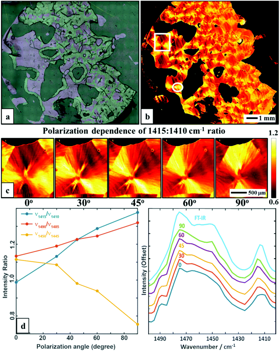 | ||
| Fig. 1 (a) Optical microscopy image of a PEG polymer film. (b) Intensity map of 1415:1410 cm−1 ratio at 0° polarization visualizing the spherulite crystal structure. (c) A zoom of area in the white box in b, taken with 5 polarizations: 0, 30, 45, 60 and 90, respectively. (d) Polarization dependence of selected bands ratios. (e) Average spectra in the 1400–1500 cm−1 range of a selected region (white circle) taken with different polarizations and compared to a FT-IR spectrum of the same sample. The spectra have been offset for clarity. | ||
We next measured the major, crystal structure-sensitive IR spectral region (1400–1500 cm−1, with 5 cm−1 step and 5 polarizations), which required ∼8 h. A similar measurement with FT-IR imaging would require about an order of magnitude larger time, though a straightforward comparison is not possible due to the difference in intensity, optical setups and spectral region mismatches. Nevertheless, we note that the new approach should provide the same quality and fidelity of data as FT-IR imaging. Here, we compare spectral properties from the two modes and later in the manuscript will compare the performance or ability to provide information. A comparison of average spectra with different polarizations is shown in Fig. 1e – a corresponding non-polarized FT-IR average spectrum of a selected region is also given. The spectra highlight several polarization-dependent spectral changes. Of course, the FT-IR data can be unpolarized as they originate from a globar source. For the QCL, light is polarized, so the data at two polarizations can be combined to provide isotropic-equivalent data. Here, our goal was not to reproduce the spectrum but to examine its variation with polarization and position. The spectral changes with polarization, shown in Fig. 1e, indicate both the potential for robust analytical measurements but also significant spectral differences within the PEG spherulite sample, necessitating an imaging approach.
A two wavenumber approach seems sufficient to visualize spherulite structure, however, in the case of a less structured sample region it will not be sufficient. An example is shown in Fig. 2f, where the borders of the spherulite are not easily discernible with just one polarization. Such issues are not usually reported for FT-IR imaging given the limited size of the spatial sample, practitioners have tended to focus on well-defined regions of the sample. With the faster imaging focusing on a few key indices, the greater spatial extent and diversity within the sample can be observed. To compare the structural information on a common scale and to utilize the polarization information, we propose to use the dependence of the absorbance at a given angle Aγ, as described in eqn (1). From this, we calculate Hermans orientation function or the “in-plane orientation function (fψ)” as shown in eqn (2), which corresponds to the magnitude of molecular chain orientation in the sample plane.1,2 These relationships are given by
 | (1) |
 | (2) |
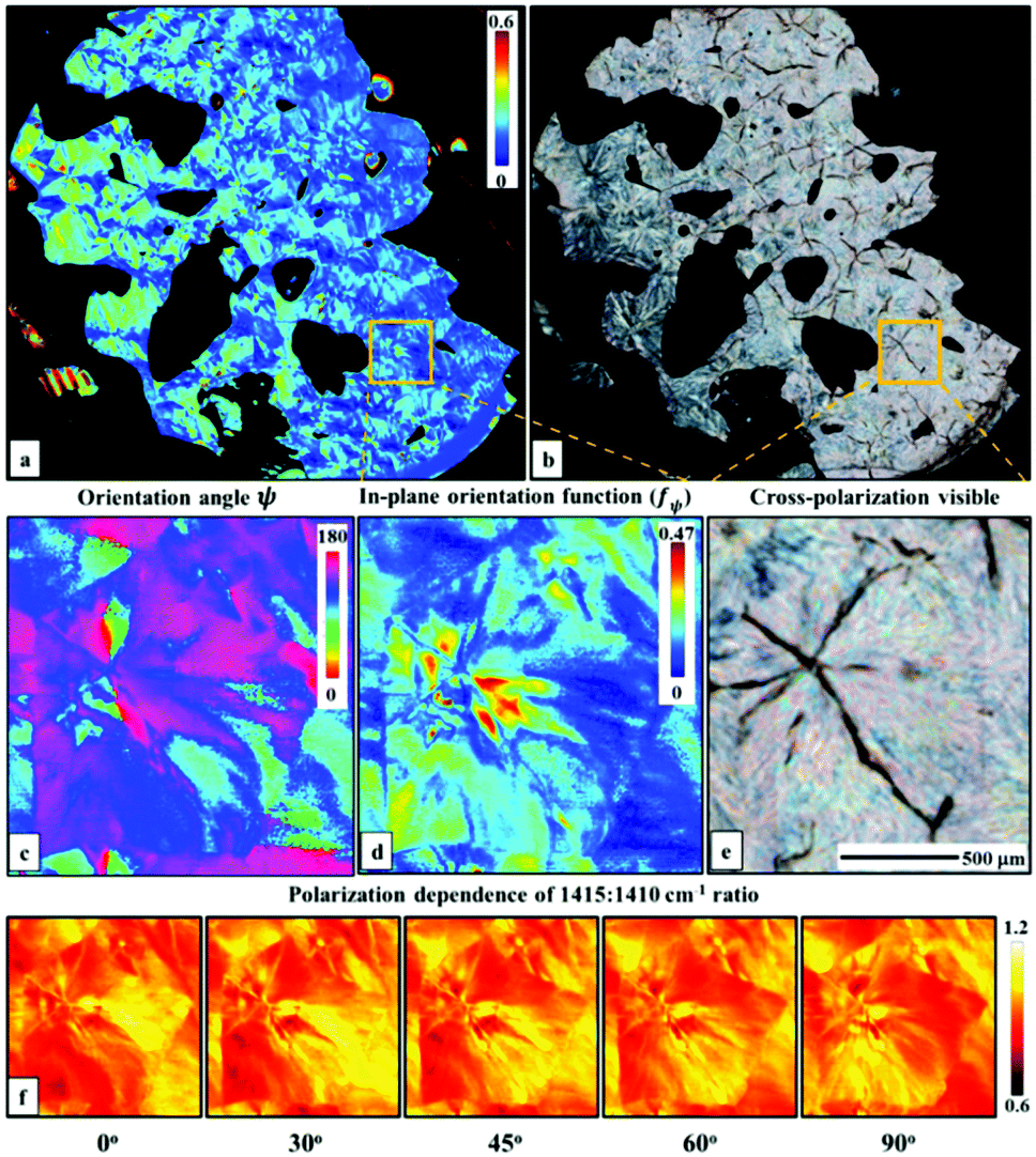 | ||
| Fig. 2 (a) In-plane orientation function calculated using CH2 wagging vibration at 1410 cm−1. (b) A visible cross-polarization image. (c) Azimuthal angle distribution of molecular chains in the zoom from (a). (d) A zoom in of the in-plane orientation function of (a) showing the borders of the spherulite. (e) A zoom in on the same area in the cross-polarization visible image. (f) 1415:1410 cm−1 ratio distribution with different polarizations of the same area. | ||
While the method can provide spectral data and measures of molecular orientation, we must ensure that the fidelity of the data is the same or better than the well-established FT-IR imaging systems. Hence, we compared the performance of the QCL microscope (at 5 μm × 5 μm per pixel) with an FT-IR Linear Array (6.25 μm × 6.25 μm per pixel) system using an USAF1951 target made of SU-8 polymer and shown in Fig. 3a and b. Both the images are obtained by plotting the absorbance at 1510 cm−1. A profile of element 4 in group 5 (marked with a line) shows comparable performance. Notably, the absorbance line profile from a single point QCL microscope does not show the effects of a coherent IR source in a wide-field illumination, e.g. diffraction on the edges, as has been previously reported for wide-field configurations.9–11 A single pixel SU-8 spectrum (Fig. 3e) shows very good agreement between two systems. Finally, a measure of spatial noise performance was calculated in the form of root-mean-squared (RMS) absorbance of an empty region for each of the wavenumbers, as described previously.11 For this set of measurement parameters, the linear-array FT-IR spectrometer has better noise characteristics than the QCL system, likely due to the liquid nitrogen cooled detector, electronic filtering of Fourier frequencies in the interferogram and multichannel detection advantage. However, the linear array system is too slow to be suited to imaging large areas for which FPA-based systems are well-suited. Assuming the requirement of an FPA FT-IR spectrometer of 16 scans to obtain a similar SNR and a scan time of 2.5 minutes per 128 × 128 tile with a 5.5 μm per side per pixel, the spherulite image would take approximately (18 × 18 tiles) 810 minutes for one polarization and 1620 minutes for two. The time for the QCL microscope measuring two frequencies or two polarizations of one frequency with pixel size of 5 μm is roughly equal to 9 minutes, giving a speed enhancement factor of ∼180. We emphasize that this advantage is valid only for the minimal number of frequencies measured with the QCL system, since as this number would grow the performance would get closer and closer to that of an FPA FT-IR imaging system. In situations where only a few discrete frequencies are required, the QCL system will outperform an FPA FT-IR imaging microscope with the technology available at present. This observation is consistent with other studies performed using widefield QCL imaging as well.11
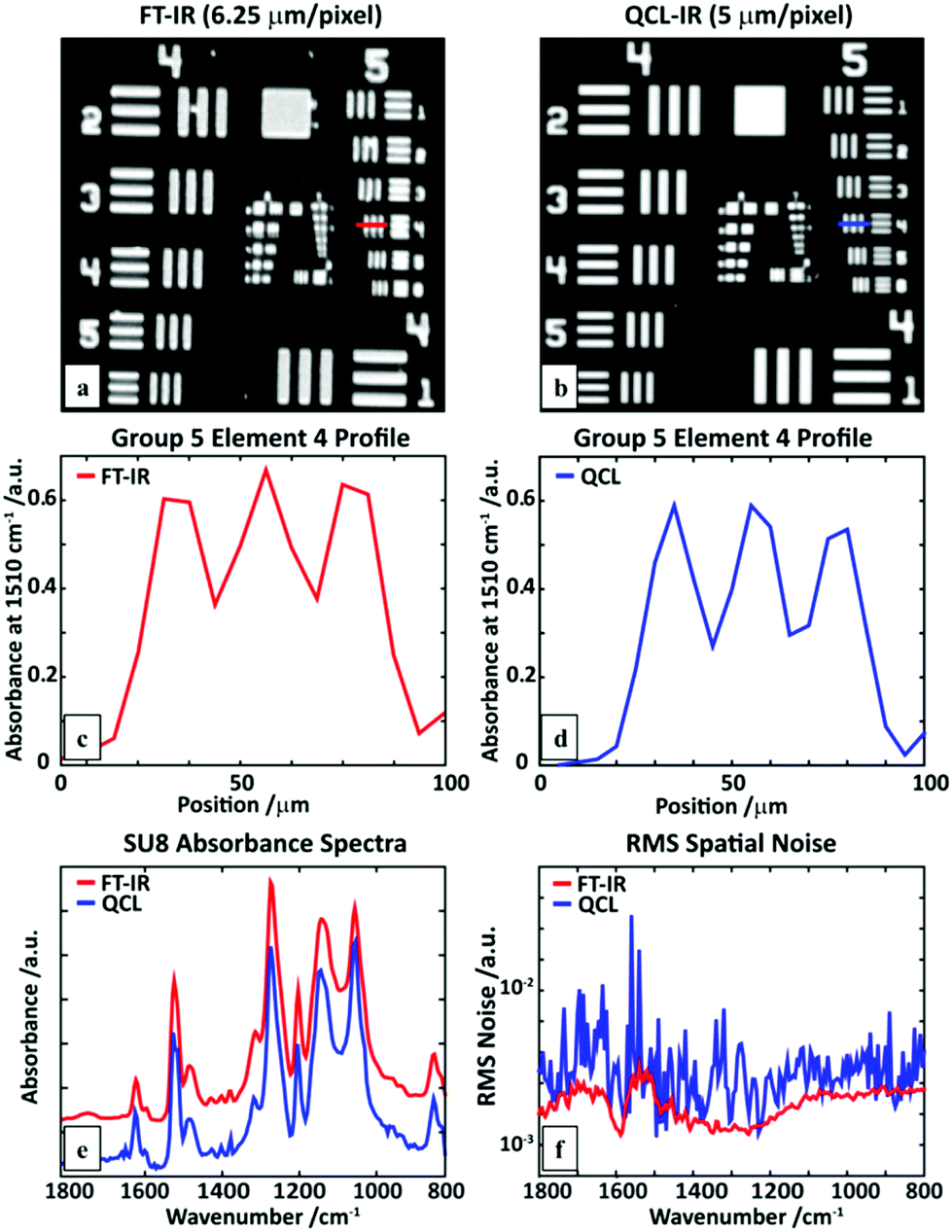 | ||
| Fig. 3 An SU-8 USAF1951 target image at 1510 cm−1 obtained using a (a) linear-array FT-IR imaging system, and (b) a QCL microscope. A line profile of element 4 of group 5 measured with (c) the FT-IR, and (d) QCL microscope. (e) A comparison of single pixel polymer (SU8) absorption spectra, showing close correspondence. (f) Root-mean-squared (RMS) values of the absorbance in a region without sample (100% line), calculated for the full QCL spectral range. | ||
Conclusions
This study demonstrates the rapid imaging of large polymeric samples using the emerging approach of discrete frequency IR imaging. The spatial coverage that allows an appreciation of cm, μm- and molecular-scale structure. Measurements with as little as two frequencies allow visualization of spherulite structure within the semi-crystalline PEG sample. The use of the inherent polarization of the laser and analysis by the Hermans in-plane orientation function allows more structural insight than a cross-polarized visible image, without requiring an excessively long time for data acquisition. Both the temporal gains and the ease of use of this approach should provide new opportunities for analysis of μm-to-cm scale morphology and molecular structure in macromolecular systems.Conflict of interest
The authors declare no competing financial interest.Acknowledgements
We are grateful to the Chevron Phillips Chemical Company, LP for financial support and to Paul DesLauriers and Mark J. Lamborn for discussions. TPW acknowledges support through “Mobility Plus” program from the Polish Ministry of Science and Higher Education.Notes and references
- Y. Hikima, J. Morikawa and T. Hashimoto, Macromolecules, 2012, 45, 8356–8362 CrossRef.
- Y. Hikima, J. Morikawa and T. Hashimoto, Macromolecules, 2013, 46, 1582–1590 CrossRef.
- E. N. Lewis, P. J. Treado, R. C. Reeder, G. M. Story, A. E. Dowrey, C. Marcott and I. W. Levin, Anal. Chem., 1995, 67, 3377–3381 CrossRef PubMed.
- C. M. Snively and J. L. Koenig, J. Polym. Sci., Part B: Polym. Phys., 1999, 37, 2353–2359 CrossRef.
- J. Kressler, R. Schafer and R. Thomann, Appl. Spectrosc., 1998, 52, 1269–1273 CrossRef.
- A. Gupper, K. L. A. Chan and S. G. Kazarian, Macromolecules, 2004, 37, 6498–6503 CrossRef.
- K. L. A. Chan, L. Govada, R. M. Bill, N. E. Chayen and S. G. Kazarian, Anal. Chem., 2009, 81, 3769–3775 CrossRef PubMed.
- A. V. Ewing, G. S. Clarke and S. G. Kazarian, Biomicrofluidics, 2016, 10, 024125 CrossRef PubMed.
- T. P. Wrobel, M. R. Kole and R. Bhargava, Spectroscopy, 2016, 31, 28–45 Search PubMed.
- M. R. Kole, R. K. Reddy, M. V. Schulmerich, M. K. Gelber and R. Bhargava, Anal. Chem., 2012, 84, 10366–10372 CrossRef PubMed.
- K. Yeh, S. Kenkel, J.-N. Liu and R. Bhargava, Anal. Chem., 2015, 87, 485–493 CrossRef PubMed.
- N. Kröger, A. Egl, M. Engel, N. Gretz, K. Haase, I. Herpich, B. Kränzlin, S. Neudecker, A. Pucci, A. Schönhals, J. Vogt and W. Petrich, J. Biomed. Opt., 2014, 19, 111607 CrossRef PubMed.
- G. Clemens, B. Bird, M. Weida, J. Rowlette and M. J. Baker, Spectrosc. Eur., 2014, 26, 14–19 Search PubMed.
- N. Suttiwijitpukdee, H. Sato, M. Unger and Y. Ozaki, Macromolecules, 2012, 45, 2738–2748 CrossRef.
- J. C. Rodríguez-Pérez, I. W. Hamley and A. M. Squires, Biomacromolecules, 2011, 12, 1810–1821 CrossRef PubMed.
- B. D. C. Vidal, Acta Histochem., 2013, 115, 686–691 CrossRef PubMed.
- I. Brand, F. Habecker, M. Ahlers and T. Klüner, Spectrochim. Acta, Part A, 2015, 138, 216–224 CrossRef PubMed.
- R. Bhargava, S. Wang and J. L. Koenig, Adv. Polym. Sci., 2003, 163, 137–191 CrossRef.
- T. Usami and S. Takayama, Polym. J., 1984, 16, 731–738 CrossRef.
- C. Baker and W. F. Maddams, Die Makromol. Chem., 1976, 437–448 CrossRef.
- W. F. Maddams, D. B. Morris and H. A. Willis, Polym. Commun., 1989, 30, 180–181 Search PubMed.
- C. J. Neves, E. Monteiro and A. C. Habert, J. Appl. Phys., 1993, 50, 817–824 Search PubMed.
- B. Wolf, S. Kenig, J. Klopstock and J. Miltz, J. Appl. Polym. Sci., 1996, 62, 1339–1345 CrossRef.
- C. Baker, W. F. Maddams, G. S. Park and B. Robertson, Die Makronwlekulare Chem., 1973, 165, 321–323 CrossRef.
- R. Popli and L. Mandelkern, J. Polym. Sci., Part B: Polym. Phys., 1987, 25, 441–483 CrossRef.
| This journal is © The Royal Society of Chemistry 2017 |