Handling diazonium salts in flow for organic and material chemistry
Nicolas
Oger
a,
Erwan
Le Grognec
a and
François-Xavier
Felpin
*ab
aUniversité de Nantes; UFR des Sciences et des Techniques, CNRS UMR 6230, CEISAM, 2 rue de la Houssinière, 44322 Nantes Cedex 3, France. E-mail: fx.felpin@univ-nantes.fr
bInstitut Universitaire de France, 103 blvd St Michel, 75005 Paris Cedex 5, France
First published on 17th March 2015
Abstract
This review gives an overview of transformations involving the use of diazonium salts in flow. The efficiency of the strategies is critically discussed with a special emphasis on the design of the flow devices. If comparative studies with batch chemistry is provided, the input of flow chemistry with regard to the reaction yields and safety issues is discussed as well.
1. Introduction
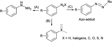
Aryl diazonium salts have aroused interest from both academic laboratories and industry for their vast synthetic potential.1 These compounds are considered as a class of “super-electrophiles” due to the high reactivity of the nitrogen function which allows them to react under mild conditions. The diazonium function can be reduced into the corresponding hydrazine2 (Scheme 1A) or formally substituted by a variety of atoms including hydrogen, halogens, sulfur, oxygen, nitrogen and carbon following radical or ionic pathways (Scheme 1B).3–5 Moreover, the electrophilic diazonium function allows the addition of nucleophile furnishing azo-compounds that are the core element of many dyes and pigments (Scheme 1C).6,7Aryl diazonium salts are traditionally prepared by diazotisation of the corresponding aniline with a source of nitrite (NaNO2 or an alkyl nitrite) in the presence of either an inorganic or an organic acid (e.g. HCl, HBF4, H2SO4, RCO2H, RSO3H…) acting as a proton donor and a counterion.
Despite their incredibly large spectra of reactivity, aryl diazonium salts are still under-used due to their potential hazardous behavior especially on large scale. This major drawback has been minimized by a DSC study whereby the authors showed that aryl diazonium tosylates could be stable under elevated temperature conditions8 and many industrial processes have also been developed under safe conditions.9–14 However, in order to avoid the handling of hazardous compounds, many methodologies have been reported whereby aryl diazonium salts were generated in situ and further reacted without isolation.15–19
Regarding the handling of hazardous compounds, continuous flow chemistry has emerged as an enabling technology that enhance safety due to the small size of the reactor.20–34 The facile automation of flow device, allowing the precise control of the reaction parameters, and the high volume to surface ratio, increasing heat and mass transfers, allows a number of benefits including increased safety, higher reproducibility and better kinetics. Moreover, the scale-up in flow is easier compared to the tedious batch scale-up process by increasing the size and/or the number of reactors.35,36
In this review, we aim to get a picture of processes involving the use of aryl and even alkyl diazonium salts in flow chemistry. Each approach is exposed with the support of selected relevant examples and the flow setup is clearly detailed. Whenever possible, comparison with batch chemistry is presented and critically discussed. This review does not cover the use of aryl diazonium salts in batch, and the reader can further refer to recently published reviews.4,5,19,37–41 Importantly, we stress that this review does not address safety investigations of diazonium salts, since they largely depend on their structure and is out of the scope of this monograph. It should also be mentioned that a recent mini-review briefly discussed the use of diazo and diazonium species in flow, but the scope was intentionally restricted to selected examples.42
2. Nucleophilic addition on the diazonium function
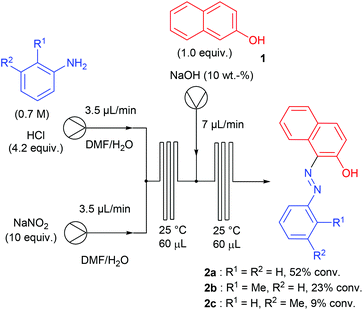
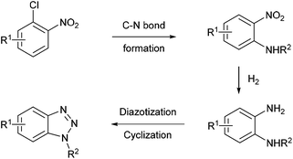
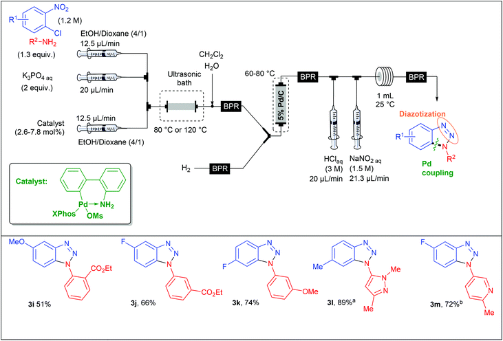
Aryl diazonium salts have been discovered by P. Griess in 1858 who worked on the synthesis of dyes.43 This seminal discovery has led to intense research efforts focusing on the preparation of original azo-dye compounds and has strongly participated to the development of the industry of colour chemicals.44–48 This chemistry has been implemented in a flow reactor by the group of de Mello, who pioneered the chemistry of aryl diazonium salts using microfluidic reactors, through a two-step synthesis including a diazotisation/azo-formation sequence.49 To reach this goal, a three-stream micro-capillary flow reactor having a channel width of 150 μm and a channel depth of 50 μm was designed (Scheme 2). A first pump was fed with a solution of aniline (1 equiv., 0.7 M) and HCl (4.2 equiv.) in DMF–H2O while a second pump was fed with an aqueous solution of sodium nitrite (10 equiv.) in DMF–H2O in order to complete the diazotisation step at room temperature in a first micro-capillary reactor. The resulting flow stream (7 μL min−1) was mixed with a basic aqueous solution of β-naphthol 1 (1 equiv.) pumped at 7 μL min−1 and then, the diazonium salt underwent a nucleophilic addition at room temperature in a second micro-capillary reactor. According to the authors, the diazotisation step was not optimised and the whole process suffered from poor conversions (9–52%) on only three examples.Recently, the group of S. L. Buchwald described an elegant synthesis of benzotriazoles,50 addressing the recurrent issues of regiocontrol encountered with traditional approaches.51–53 In this regard, the authors designed a multistep flow synthesis consisting of a C–N bond formation/hydrogenation/diazotisation/cyclization sequence starting from 2-chloronitrobenzenes and amines (Scheme 3).
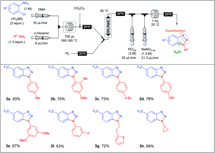
In a first approach, S. L. Buchwald et al. envisaged the formation of the C–N bond through a nucleophilic aromatic substitution. The flow device consisted in a first syringe pump fed with chloronitrobenzene (1 equiv., 1 M) and i-Pr2NEt (2 equiv.) in DMA at a 16 μL min−1 flow rate and mixed into a T-shaped mixer with a second flow stream composed of the amine (1.3 equiv.) at a 8 μL min−1 flow rate in n-hexanol (Table 1). The SNAr occurred in a stainless steel coil reactor (700 μL) for 30 minutes at a temperature range of 160–180 °C. The resulting mixture was diluted in CH2Cl2 in order to carry out the hydrogenation step at 45 °C whereby hydrogen gas was mixed with the liquid flow stream to form a segmented flow stream. The latter went to a vertically placed packed-bed reactor filled with stainless steel spheres and 5 wt% Pd/C particles (250 mg). The authors observed that their hydrogenation step was better achieved with a vertically placed reactor. Indeed, reactors packed with stainless steel spheres lead to unpredictable packed catalytic beds. Thus, a turbulent flow stream appears for horizontally placed reactors resulting in poor mass and heat transfers and therefore in a lower efficiency than for a vertically placed packed-bed reactor where the flow stream is closer to a laminar flow.21 Then, the last two steps were carried out at room temperature in a PFA coil reactor (1 mL) with the use of aqueous HCl (3 M) and aqueous NaNO2 (1.5 M) as diazotising agents. Finally, the crude solution was collected and purified to afford the desired products in good to excellent yields (63–93%). The reaction scope revealed that the strategy was limited to chloronitrobenzenes bearing electron-withdrawing groups in order to achieve the nucleophilic aromatic substitution with good conversion while a large variety of both aromatic and aliphatic amines were compatible with this multistep process.
With the aim of expanding the reaction scope, the authors developed another strategy whereby the C–N bond formation step was performed through a Pd-catalysed Buchwald–Hartwig amination. For this second approach, they assembled a new microfluidic system as shown in Table 2. In this flow setup, a solution of chloronitrobenzene (1 equiv., 1.2 M), amine (1.3 equiv.), aqueous K3PO4 (2 equiv.) and catalyst (2.6–7.8 mol%) in EtOH–Dioxane (4/1) went through a packed-bed reactor filled with stainless steel spheres and submerged in an ultrasonic bath to avoid clogging issues. The three other steps of the sequence were performed following a similar flow setup than that used for the first approach. This complementary strategy considerably expanded the reaction scope since both electron-deficient and electron-rich chloronitrobenzenes were allowed, leading to variously decorated benzotriazoles in fair to excellent yields (51–89%).
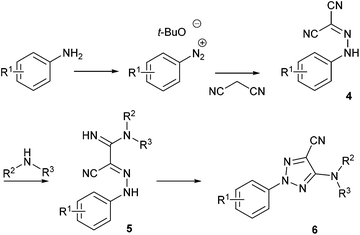
Recently, Pasau and Jacq at UCB Biopharma described a sequential multistep flow synthesis of 5-amino-2-aryl-2H-[1,2,3]-triazole-4-carbonitriles 654 which are a well-known class of antifungal agents.55 The current strategy reported in the literature to reach these compounds is a four steps synthesis whereby one of the key steps involves a nucleophilic addition of malononitrile onto a diazonium function (Scheme 4). In order to address safety concerns associated with the use of diazonium salts, especially for large-scale reactions, authors developed a flow approach.
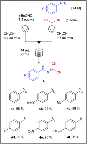
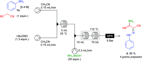
Each intermediate was isolated except the diazonium salts since they were trapped in situ by the malononitrile moiety. For the diazotisation/diazonium quench sequence, a first pump was fed with aniline (1 equiv., 0.4 M) and malonitrile (1 equiv.) in CH3CN while a second pump was fed with t-BuONO (1.3 equiv.) in CH3CN. The two flow streams were telescoped in a T-mixing piece and went through a PFA coil reactor (14 mL) at room temperature. It is noteworthy that this transformation did not require the use of an acid, suggesting that a small amount of diazonium t-butanolate salt was formed in situ and instantly consumed thanks to the nucleophilic addition of the malononitrile. Thus, 2-arylhydrazonomalononitriles 4a–f were obtained in very good yields (90–99%, Table 3) on six examples without any problem of reactivity whatever the electronic nature of the substituents decorating anilines. This reaction was performed on a 40 mmoles scale leading to a maximum throughput of 16.8 mmol h−1.
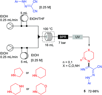
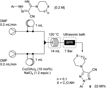
The remaining two steps, i.e. amidine formation and oxidative cyclization, were also carried out in flow using two independent two-stream flow devices. The amidines 5 were prepared by addition of amines to 2-arylhydrazonomalononitriles 4 (Scheme 5). The reaction setup employed two ways equipped with 5 mL injection loops. The first loop was loaded with the 2-arylhydrazonomalononitriles 4 in EtOH–THF, while the second loop was filled with a solution of amines in EtOH. Pumping of each way was conducted at 0.25 mL min−1 and the flow streams met at a T-shaped mixer before entering into the reaction coil (16 mL) held at 100 °C. The line was pressurised with a back-pressure regulator at 7 bar and the amidines 5 were collected through an UV-triggered fraction collector. Last, the desired triazoles 6 were obtained by copper(II)-catalysed oxidative cyclisation of 2-arylhydrazonomalononitriles 5 (Scheme 6). The reaction setup consisted of two 1 mL injection loops containing the material required for the oxidative cyclization that met at a T-piece and entered in a 14 mL coil reactor heated at 120 °C. The line was pressurised at 7 bar with a back-pressure regulator immersed in a sonication bath to avoid the precipitation of inorganic species leading to clogging issues.
The opportunity to achieve multi-step sequences with a single flow device was studied for the synthesis of 2-phenylhydrazonomalono-2-cyanoacetamidine 5 from aniline 7a, malononitrile and ammonia (Scheme 7). The 2-phenylhydrazonomalononitrile 4a, prepared as described above, was mixed in a T-shape mixer with a 7 M ammonia solution stream in MeOH (35 equiv.) at a 0.3 mL min−1 flow rate. The resulting mixture (total flow rate = 0.6 mL min−1) went through PFA coil reactors (2 × 10 mL) heated at 110 °C and pressurised at 8 bar. For 6.25 hours of continuous working, more than 4 grams of product 5 (95% yield) were collected in good purity after elimination of the volatiles.
3. Reduction of the diazonium function
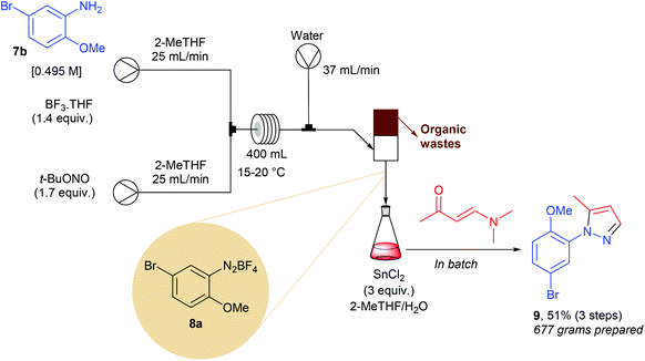
The Knorr cyclocondensation of hydrazines with 1,3-dicarbonyl compounds or their surrogates is a well-known transformation that offers a straightforward access to N-aryl pyrazoles.56 These heterocycles are key pharmacophores in many marketed drugs such as celecoxib, rimonabant, sildenafil as well as crizotinib, and are therefore of high interest in medicinal chemistry. While many 1,3-dicarbonyl compounds are commercially available, the molecular diversity of commercial aryl hydrazines is quite narrow. One of the most efficient way to prepare aryl hydrazines consists in the sequential diazotisation of anilines into the corresponding diazonium salts, followed by the reduction of the diazonium function. Owing to the potential safety hazard of both diazonium salts and hydrazines, especially for scale-up, Li and co-workers developed a continuous flow approach.12 In preliminary optimization studies they observed that unreacted t-BuONO, used in a slight excess in the diazotisation step, gave rise to several impurities during the reduction step. To address this issue, the authors designed an ingenious continuous extraction allowing the separation of the water-soluble diazonium salt 8a from the unwanted organic-soluble side-products. The flow setup consisted of two initial streams each working at 25 mL min−1 (Scheme 8). The first pump was fed with aniline 7b (1 equiv., 0.495 M) and BF3·THF (1.4 equiv.) in 2-MeTHF while the second one carried out a solution of t-BuONO (1.7 equiv.) in 2-MeTHF. The two streams met at a stainless steel T-mixer before entering in a PTFE 400 mL coil reactor with 8 min residence time. The resulting effluent containing the diazonium salt in 2-MeTHF (50 mL min−1) was mixed with a third stream of water, introduced at a flow rate of 37 mL min−1, to give a biphasic mixture that was separated in a glass standpipe decanter. The organic phase containing impurities was continuously removed while the aqueous layer was poured in a jacketed 75 L reactor containing SnCl2 (3 equiv.) in a mixture of 2-MeTHF and water for the reduction of 8a into the corresponding hydrazine. After 2 hours, (3E)-4-(dimethylamino)but-3-en-2-one was added to the resulting mixture to give, after purification on silica gel, 677 g of the expected pyrazole 9 (51% for the three steps). This approach was particularly efficient for the preparation of pyrazoles on scale lower than 1 kg. For larger scale, improvements on the product purification will be required to avoid the use for several kg of silica gel and tens liters of 2-MeTHF as eluent.4. Formation of C–X bonds
4.1. C–halogen bonds
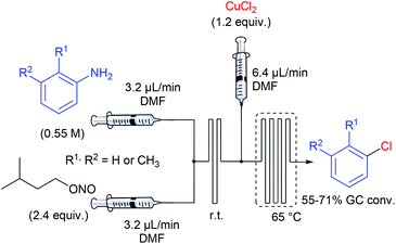
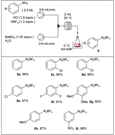
In one of their seminal reports, de Mello and co-workers demonstrated that the use of monolithic microfluidic reactors were particularly pertinent with regard to the formation of diazonium salts in anhydrous conditions and their subsequent chlorination or hydrodediazotisation.57 Indeed, reagents mixing, quench addition and heated dediazotisation operations can be safely handled with the support of a single microdevice (Scheme 9). More specifically, authors studied the Sandmeyer reaction of aniline, o-toluidine and m-toluidine with CuCl2, giving the corresponding chloroarenes. The device, consisting of a glass microchip elaborated in-house, includes a first T-shaped inlet followed by a short serpentine of 80 mm in length for the diazonium formation and a second inlet channel introducing a solution of copper chloride in DMF, followed by a long serpentine of 280 mm in length, heated at 65 °C and ended by an exhaust. Remarkably, they demonstrated that on-line Raman spectroscopy can be an efficient real-time tool for monitoring the diazonium formation through the glass microdevice. Unfortunately, the process was not optimised and the yields for the chloroarenes were not reported excluding a more detailed discussion on the real efficiency of such a technology with regard to batch chemistry.The Balz–Schiemann reaction is a classic for preparing aryl fluorides from the corresponding aryl diazonium salts.58 However, large-scale reactions face several difficulties including: (1) the hazardous properties of isolated diazonium salts, (2) the mixing of heterogeneous mixtures, and (3) the heat transfer in multi-phasic media. In order to address these issues, Yu et al. have developed a continuous flow approach for preparing aryl fluorides by thermally-mediated fluorodediazotisation of the corresponding aryl diazonium salts, also prepared in flow.59 For some reasons, diazotisation and fluorodediazotisation processes were studied separately, and the use of a single flow device allowing the two-step sequence without isolation of hazardous diazonium salts was not investigated. The diazotisation was carried out at 25 °C and diazonium salts were collected in a flask immersed in an ice-bath (Table 4). The reaction setup consisted in a first pump fed with a solution of aniline (1 equiv., 2 M), hydrochloric acid (1.8 equiv.) and tetrafluoroboric acid (1.2 equiv.), and a second pump fed with an aqueous solution of sodium nitrite (1.05 equiv.). The two streams met in a T-joint and entered in a 2 mL coil reactor at 6–12 ml min−1 corresponding to only 15 ± 5 seconds residence time according to the aromatic amine. The electronic nature of the substituents did not significantly impact the reaction efficiency and the corresponding salts were isolated in high yield (86–98%).
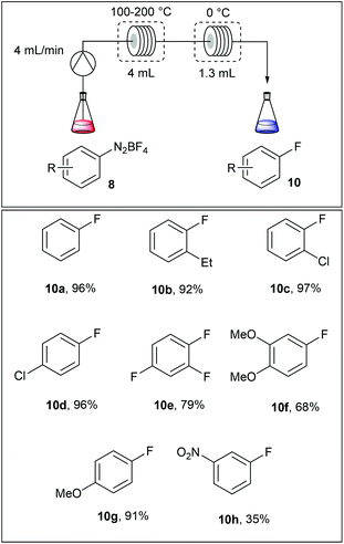
The fluorodediazotisation step was carried out using a simple flow device as depicted in Table 5. A solution of the diazonium salt was pumped at 4 mL min−1 into a 4 mL coil reactor heated at 110–200 °C and, immediately after, the reaction mixture was cooled in a second coil reactor immersed in an ice bath. Surprisingly, authors selected the fluoro compounds 10a–h as solvents for the reaction media, limiting this approach to commercially available fluoroarenes. Moreover, the dediazotisation step proceeded exclusively with diazonium salts bearing electron releasing groups since with m-nitrobenzenediazonium salt 8i the yield fell down to 35%.
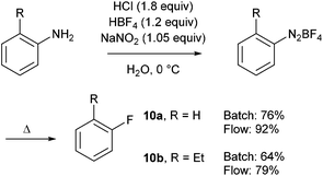
In order to compare their flow approach with a traditional batch process, parallel experiments were carried out with two different anilines (Scheme 10). This comparative study showed that each step was better achieved in flow whereas the use of electron-poor anilines was overlooked.
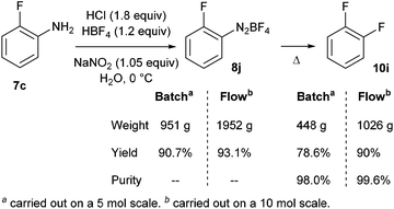
Finally, a continuous kilogram-scale process for the manufacture of o-difluorobenzene 10i was successfully achieved using the same flow device (Scheme 11).13 The better result obtained in flow compared to the traditional batch process was attributed to better mass and heat transfers, improving purity and yield.
4.2. C–S bonds
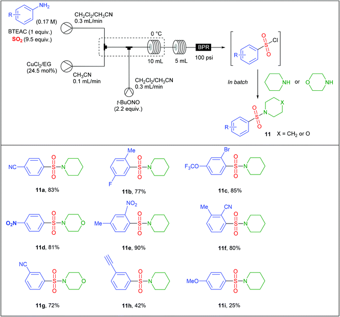
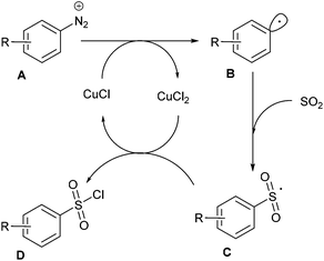
The group of S.V. Ley at Cambridge University has also significantly impacted this area of research.22,23,26 For instance, Ley et al. safely adapted a Sandmeyer-type chlorosulfonylation of aryl diazonium salts60 that was initially reported in batch in the late 1950s by Meerwein.61 Since the original conditions, involving the diazotisation of anilines by NaNO2 in aqueous HCl followed by the CuCl2-mediated chlorosulfonylation under an atmosphere of SO2, could not be implemented in flow due to the generation of insoluble species, they proposed a profoundly modified procedure. In preliminary studies, they identified that NaNO2 and CuCl2 were poorly soluble in the reaction media while HCl led to corrosion of the pump heads of the flow device. To fix these issues, they replaced NaNO2 by t-BuONO and avoided the use of HCl as a source of chloride by employing benzyltriethylammonium chloride (BTEAC). They chose to address the insolubility issue of CuCl2 by using an immobilised copper catalyst consisting of Amberlyst 21 loaded with CuCl2. Since SO2 is highly soluble in CH3CN, this was chosen as co-solvent in association with a water immiscible solvent such as dichloroethane or dichloromethane with the aim of using an in-line aqueous workup. Unfortunately, authors observed that the active catalyst was a solubilised copper species that leached form the support, leading to a rapid deactivation of the cartridge. Therefore, they decided to explore the use of a homogeneous copper catalyst coordinated with a ligand in order to increase its solubility in organic solvents. After several catalyst/ligand combination they found that CuCl2 was rendered soluble in organic solvents through coordination with ethylene glycol (EG), a good water soluble ligand that can be removed during the aqueous workup. Therefore, the authors designed a three-stream flow setup as depicted in Table 6. In a first inlet a solution of aniline (1 equiv., 0.17 M), BTEAC (1 equiv.) and SO2 (9.5 equiv.) in a mixture of CH2Cl2–CH3CN was mixed in a T-shaped mixing chamber with a solution of CuCl2–EG (24.5 mol%) in CH3CN introduced through a second inlet. The resulting solution was immediately mixed in a T-piece with a third stream consisting of t-BuONO (2.2 equiv.) in CH2Cl2–CH3CN. The resulting reaction mixture was then passed in a 10 mL coil reactor immersed in an ice bath to prevent any uncontrolled decomposition of diazonium salts, followed by a second 5 mL coil reactor and a back pressure regulator (100 psi), both held at room temperature. During the workup, piperidine or morpholine was added to the organic layer in order to avoid the decomposition of sensitive sulfonyl chlorides. The substrate scope of the reaction (Table 6) was carried out on thirteen examples with low to high yields (25–90%); anilines bearing electron-releasing groups giving the lowest yields. Interestingly, authors successfully scaled-up their device by increasing both the flow rate and the reactor volume by a factor of 4, in order to keep constant the residence time. On a single example, they were able to produce the 2-cyano-3-methyl-benzenesulfonyl chloride in 95% yield, corresponding to a throughput of 2 g h−1 (10 mmol prepared).The mechanism of this transformation likely involves an aryl radical intermediate B, generated by the cuprous chloride-catalysed homolytic dediazotisation, which reacts with sulfur dioxide to give the sulfonyl radical C (Scheme 12). The latter was then converted to the sulfonyl chloride adduct D upon oxidation by cupric chloride.
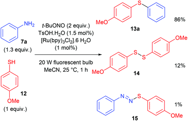
The construction of C–S bonds from diazonium salts and thiols is a very old process, known as the Stadler–Ziegler reaction that has found many applications in industry for manufacturing aryl sulfides.62,63 Noël and co-workers developed a photocatalytic Stadler–Ziegler process using a photoredox catalysis and visible light.64 In a first stage of their work, authors optimised experimental conditions in batch in order to lower the formation of diarylsulfide 14 and diazosulfide 15 as by-products (Scheme 13). Along this work they determined that the use of t-BuONO as nitrosating agent and TsOH·H2O as proton donor in CH3CN was very efficient for the formation of the diazonium salt. The photoredox coupling of the latter with organic sulfide 12 proceeded upon light irradiation with a simple household 20 W fluorescent light source and 1 mol% [Ru(bpy)3Cl2]·6H2O as photocatalyst.
Having recorded encouraging results with both aryl and alkyl sulfides, authors further addressed safety issues associated with hazardous diazonium salts by developing a continuous flow approach (Table 7). An operationally simple device was designed, consisting in two streams controlled by a single syringe pump. The first syringe was filled with thiol (1 equiv., 0.3 M), aniline (1.3 equiv.), TsOH·H2O (1.5 mol%) and ruthenium complex (1 mol%) in acetonitrile while the second one was filled with t-BuONO (2 equiv.) in acetonitrile as well. The two streams met at a T-mixer (500 μm ID) and the resulting flow went through a PFA reactor (464 μL) irradiated with a blue LED light. The reactor was coiled around a syringe coated with an aluminum foil to refract the light on the tubing and the LED setup was coiled in a beaker coated with an aluminum foil as well. The crude solution was collected with a total flow rate of 1.86 mL min−1 in a vial and then purified by flash chromatography. For the three examples carried out, extremely low residence times (15 s) were recorded compared to the batch process (1 h); the yields in flow being in the same range than those achieved in batch. Moreover, with this flow setup, a 78-fold improvement of the throughput compared to the corresponding batch experiment was reached (13.2 mmol h−1vs. 0.17 mmol h−1). Further extending the reaction scope to electron-rich anilines and aliphatic sulfides would certainly be of great interest for synthetic chemists.
4.3. C–O bonds
The group of Ley has a long standing interest for enabling technologies in flow chemistry such as in situ analysis and in-line workup and purification.65 In this regard, Ley et al. have invented a liquid–liquid separation device using computer-controlled pumps and a high-resolution digital camera for the diazotisation/hydroxy-dediazotisation of amino acids in flow to produce chiral α-hydroxyacids 16a–f (Scheme 14).66 The process was carried out in water using a two-stream flow device. In the flow setup, an aqueous solution of amino acid (1 equiv., 0.5 M) and sulfuric acid (1 equiv.) were pumped and mixed with a stream of aqueous sodium nitrite (2 equiv.) through a T-shaped mixer. The diazotisation/hydroxy-dediazotisation sequence occurred in a 30 mL coil reactor, heated at 60 °C. The flow rate was maintained at 0.5 mL min−1 corresponding to 60 minutes residence time. Eventually, to prevent clogging issues of the tubing with the most crystalline substrates, lower concentration, higher flow rates or the use of acetone as co-solvent were necessary. One of the notable aspect of this work is the use of an in-line and automated triple extraction system providing chiral α-hydroxyacids with >95% of purity as determined by NMR or HPLC.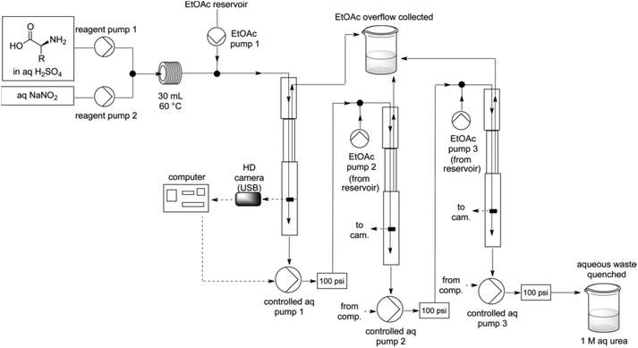 | ||
| Scheme 14 Schematic representation of the flow device. Reprinted with permission from ref. 66, copyright 2012 American Chemical Society. | ||
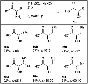
The diazotisation/hydro-dediazotisation/workup sequence was achieved with poor to excellent yields (34–92%) of crude products and excellent enantiomeric ratio (up to er 99![[thin space (1/6-em)]](https://www.rsc.org/images/entities/char_2009.gif) :
:![[thin space (1/6-em)]](https://www.rsc.org/images/entities/char_2009.gif) 1) (Table 8). The authors provided evidences for the scalability of the process since the reaction could be conducted continuously with L-valine as substrate for more than 24 hours without manual intervention, furnishing >20 g of chiral α-hydroxyvaline 16a.
1) (Table 8). The authors provided evidences for the scalability of the process since the reaction could be conducted continuously with L-valine as substrate for more than 24 hours without manual intervention, furnishing >20 g of chiral α-hydroxyvaline 16a.
| a Modified conditions (see text). |
|---|
|
4.4. C–N bonds
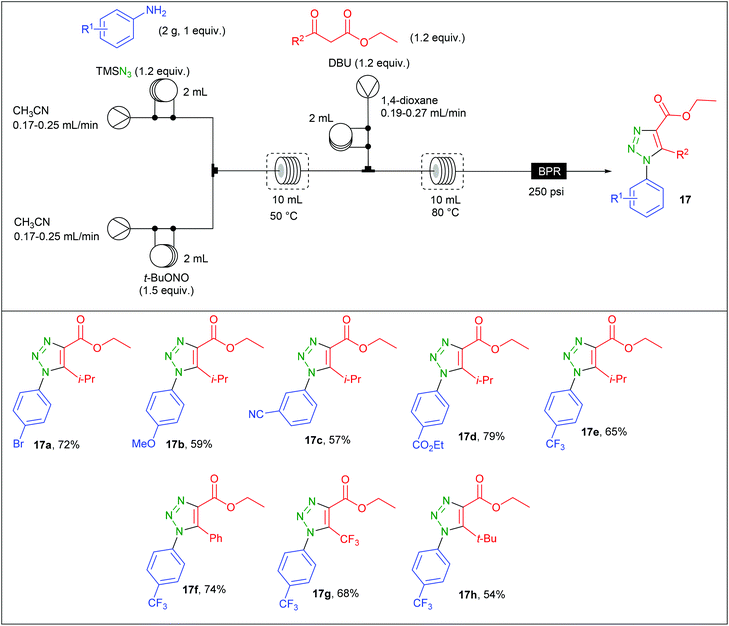
The preparation of aryl azides from the corresponding diazonium salts is a well-known transformation that found many developments.67,68 Organic azides have been intensively used in organic synthesis for the preparation of nitrogen-containing molecules including aryl 1,2,3-triazoles.69 Due to safety concerns associated with both diazonium salts and aryl azides, Bacchi et al. developed the preparation of 1,2,3-triazoles through a three-step diazotation/azidation/cyclization sequence in flow.70 The reaction was first examined in batch using p-bromoaniline as substrate. While the formation of the diazonium salt and its azidation were easily achieved using t-BuONO (1.5 equiv.) and TMSN3 (1.2 equiv.) in MeCN at 50 °C, the second step implied a screening of several bases and solvents to avoid the formation of insoluble salts initially observed by using EtONa and EtOH. After considering EtOH, MeOH, MeCN and 1,4-dioxane as solvents, EtONa, t-BuOK, TEA and DBU as bases and different temperature ranging from 60 to 80 °C, it was found that DBU and 1,4-dioxane at 80 °C afforded a complete conversion in 10 min without any precipitate formation.The implementation of this chemistry in flow was allowed with the use of a commercially available Vapourtec three-stream flow device (Table 9). The aryl azide was prepared from two streams containing respectively a solution of aniline (2 g, 1 equiv.) and TMSN3 (1.2 equiv.) in CH3CN (2 mL) for the first stream and a solution of t-BuONO (1.5 equiv.) in MeCN for the second one. These two streams met at a T-shaped mixer and the diazotisation/azidation occurred in a 10 mL coil reactor heated at 50 °C with 20–30 min residence time. Then, a third stream containing a solution of the β-ketoester (1.2 equiv.) and DBU (1.2 equiv.) in 1,4-dioxane was connected to the system through a T-piece and the resulting mixture entered in a second 10 mL coil reactor heated at 80 °C with 13–19 min residence time. The line was fitted with a back pressure regulator fixed at 250 psi. A complete regioselectivity was observed whatever the substrate and fair to good yields were obtained for triazole 17a–h (54–79%). It has to be noted that anilines with electron-donating groups were less reactive with the enolate than those with electron-withdrawing groups. This drawback was circumvented by increasing the residence time. The comparison between batch and flow procedure is here not possible since no isolated yields were given for the batch procedure.
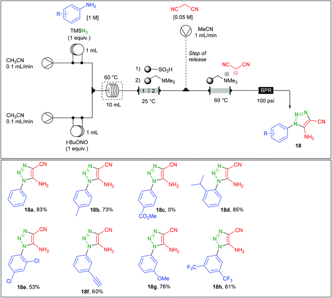
Regarding the preparation of aryl 1,2,3-triazoles, the group of Ley reported a related contribution using malononitrile instead of β-ketoesters.71 Therefore, the continuous flow synthesis of 5-amino-4-cyano-1,2,3-triazoles 18a–h was addressed with the use of a two stream-flow device (Table 10). A solution of aniline (1 equiv., 1 M) and TMSN3 (1 equiv.) in CH3CN was charged in a first 1 mL loop and mixed in a T-piece with a solution of t-BuONO (1 equiv.) in CH3CN charged in a second 1 mL loop. The diazotation/azidation occurred in a 10 mL coil heated at 60 °C with a flow rate of 0.2 mL min−1 (50 min residence time) and the resulting mixture obtained went through a glass column (8 cm length × 10 mm i.d.) containing 1.3 g of polymer-supported sulfonic acid, followed by 1.3 g of polymer-supported dimethylamine. The acid polymer allows the trapping of unreacted aniline and converts TMS-N3 to hydrazoic acid which is further trapped onto the immobilised amine. For the triazole production, the use of an immobilised malononitrile anion was preferred over the use of a third stream containing a solution of malononitrile. Authors justified this choice by the varying concentrations of the aryl azide in the main stream after having crossed the scavenging columns. Therefore, the azide stream was directed into a column (3 cm length × 15 mm i.d.) containing the malononitrile anion immobilised on a tetraalkylammonium resin and heated at 60 °C. Ironically, a third flow (1 mL min−1) containing malononitrile, used as a source of proton, was finally introduced in a second stage in order to release the triazole and regenerate the reaction column. The 5-amino-4-cyano-1,2,3-triazoles 18a–h were prepared on 1 mmol scale with a high purity after evaporation of the malononitrile with no further purification. The authors finally implemented this technology with a fully automated device allowing the production of up to 6 different triazoles over 55 hours with no manual intervention.
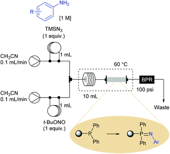
Ley et al. also demonstrated that the use of aryl azides produced in flow can be involved in a flow Staudinger aza-Wittig reaction sequence for the synthesis of imines and secondary amines.72 The Staudinger reduction was achieved with a new homemade polymer-supported triphenylphosphine reagent (loaded at 1.7 mmol of phosphorus per gram of polymer), leading to an immobilised iminophosphorane reagent that further reacted with aldehydes through an aza-Wittig reaction. This process was orchestrated in two stages with the elaboration of a first flow device dedicated to the sequence diazotisation/azidation/Staudinger reaction, followed by the use of a second device allowing the preparation of imines. The reaction setup for the preparation of iminophosphoranes consisted in a two-stream flow device (Scheme 15). The two ways were equipped with 1 mL injection loops filled with aniline (1 equiv., 1 M) and TMSN3 (1 equiv.) in CH3CN for the first one and t-BuONO (1 equiv.) in CH3CN for the second one. Each way was conducted at 0.1 mL min−1 and met in a T-piece before entering in a 10 mL coil reactor (50 min residence time) heated at 60 °C. The resulting effluent containing the aryl azides was then passed through an immobilised triphenylphosphine column (7 cm length × 10 mm i.d.) heated at 60 °C and pressurised with a back pressure regulator at 100 psi. At a flow rate of 0.2 mL min−1 the desired iminophosphorane intermediates were immobilised on polymer, ready-to-use for the next step after a simple washing to remove the excess of aryl azide and impurities.
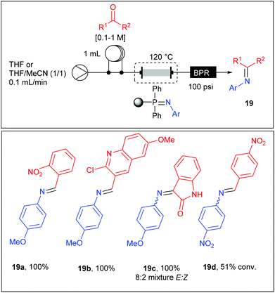
Thereby, the glass column housing the iminophosphorane monolith was connected to a stream of aldehyde (0.1–1 M) in solution in THF or THF–CH3CN (1/1) and heated at 120 °C at a flow rate of 0.1 mL min−1 (Table 11). With an active loading of the iminophosphorane estimated to 4.14 mmol, the aza-Wittig reaction was carried out with a maximum of 2 mmol of aldehyde in order to assure a high conversion. The reaction products were easily isolated as imines 19a–d after evaporation of the solvent or eventually as amines after an off-line reduction with NaBH4. Good to high yields were obtained using the 1-azido-4-methoxybenzene while no reaction was observed starting from 1-azido-4-nitrobenzene except in reaction with 4-nitro-benzaldehyde where a moderate yield was obtained. These results revealed the poor reactivity of iminophosphoranes substituted with electron-withdrawing groups, limiting the scope to electron-rich substrates. Moreover, while both electron-rich and electron-poor aldehydes were reactive, ketones failed to react except for isatin.
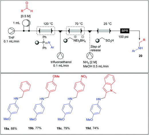
Imines being moisture sensitive compounds, the authors set a fully automated multistep flow process up incorporating an additional reduction step for the preparation of the secondary amines 20a–d (Table 12). For this purpose, a monolithic borohydride reagent housed in a glass column and heated at 70 °C was added in the main line (0.1 mL min−1) together with an additional stream of trifluoroethanol (0.1 mL min−1) which was found to be beneficial for the rate of the reduction. Upon exiting the supported borohydride column, the main stream (0.2 mL min−1) passed through a column containing a polymer-supported sulfonic acid acting as a trap for the secondary amine and allowing impurities to be washed to waste. This column allowed an in-line catch-and-release purification step, since the secondary amine can be recovered in good yield and purities upon using an additional stream of ammonia (2 M) in MeOH at a flow rate of 0.5 ml min−1.
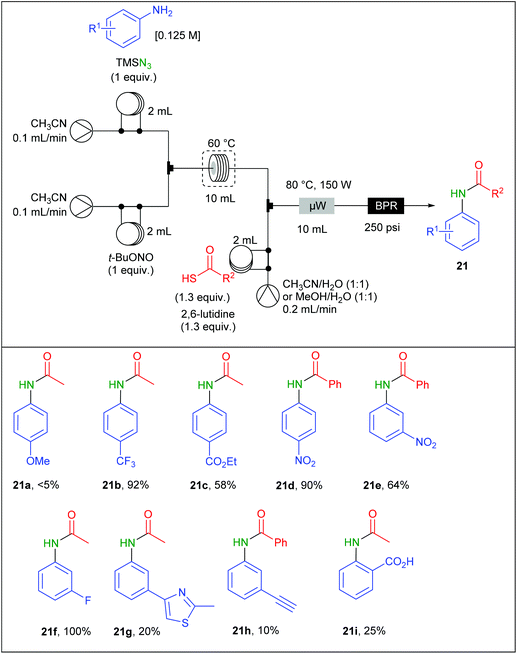
Moses and Spiteri also adapted a reaction involving aromatic azides generated from diazonium salts in flow. They previously reported a work devoted to the batch synthesis of amides involving aromatic azides and thioacids in the presence of 2,6-lutidine and under microwave heating73 but safety concerns encouraged them to propose a flow version of this preparation.74 To achieve this goal, a Vapourtec device equipped with a R4 reactor and three different pumps was connected to a CEM Discovery microwave reactor (Table 13). The process was carried out using a three-stream flow device. A solution of aniline (1 equiv.; 0.125 M), TMSN3 (1 equiv.) in CH3CN was charged in a 2 mL loop and mixed through a T-shaped mixer with a second 2 mL loop charged with a solution of t-BuONO (1 equiv.) in CH3CN. The diazotisation/azidation occurred in a 10 mL PFA coil tube reactor heated at 60 °C. The flow rate was maintained at 0.2 mL min−1, corresponding to 50 min residence time. The resulting effluent was telescoped with a third stream containing the thioacetic acid (1.3 equiv.) and 2,6-lutidine (1.3 equiv.) solubilised in a mixture of H2O and CH3CN (1/1) in a second mixing T-piece. The resulting effluent was directed to a 10 mL microwave reactor chamber irradiated at 80 °C (150 W) at 0.4 mL min−1. Both the electronic nature and the position of the substituents on the aryl ring dramatically influenced the reaction. While aniline bearing electron withdrawing groups located at meta and para positions afforded good to high yields (up to 100%), poor yields were observed with ortho-substituted anilines and aromatic rings decorated with electron donating groups (5–30%). A gram-scale amide preparation, using p-nitroaniline and thiobenzoic acid, was successfully achieved over 18 h of continuous flow synthesis with 86% yield of 21d. However, it is noteworthy that lower yields were obtained in flow compared to the batch procedure.73
5. Formation of C–C bonds
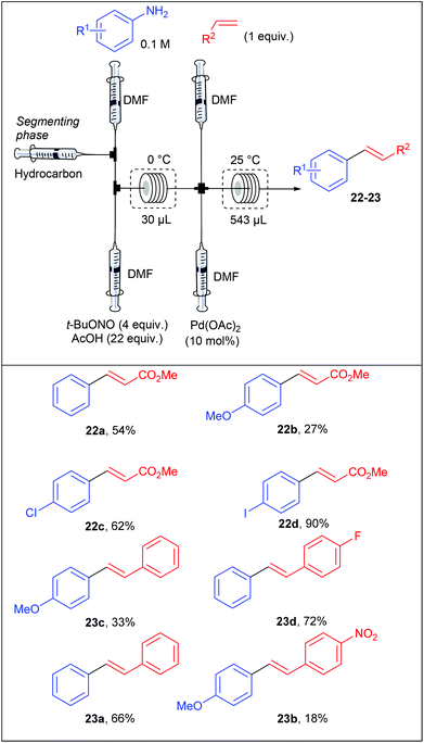
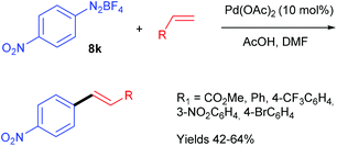
With no doubt, transition-metal catalysis has strongly contributed to the return to prominence of aryl diazonium salts in organic synthesis as powerful aryl halide and aryl sulfonate surrogates. This widespread attention, has obviously led to applications in flow chemistry. For instance, Wirth et al. performed the first Heck–Matsuda reaction carried out with a flow device from para-substituted anilines.75 They designed a flow device working with an unusual segmented flow that improve the mixing efficiency through an internal circulation (Table 14). The segmented phase, introduced through an additional syringe pump, was a linear alkane (hexane, heptane, nonane or decane) non miscible in the organic phase. The flow device, consisting of five streams supplied by syringe pumps, was designed in order to carry out a diazotisation/cross-coupling sequence. Thus, the diazotisation step consisted of two streams containing respectively the aniline (1 equiv., 0.1 M) in DMF and t-BuONO (4 equiv.) in a mixture of acetic acid (22 equiv.) and DMF. A third syringe pump, introducing the segmenting phase, was placed before the mixing chamber. The diazotisation step occurred in a reactor of 30 μL at 0 °C corresponding to a residence time of 3.2 min. The diazonium stream was telescoped in a second mixing chamber by two additional syringe pumps respectively fed with alkenes (1 equiv.) and palladium acetate as catalyst (10 mol%) at ambient temperature. The coupling step was achieved in a second reactor of 543 μL to give styrenes and stilbenes in low yields for electron-rich anilines and modest to excellent yields for neutral and electron-deficient anilines. The overall process was achieved with a remarkable 27 minutes residence time. Interestingly, a high regioselectivity at the diazonium function was observed for the coupling carried out with the p-iodoaniline and methyl acrylate.In order to demonstrate the utility of their methodology generating the diazonium salt in situ, the authors carried out the Heck–Matsuda reaction from the commercially available p-nitrobenzene diazonium tetrafluoroborate salt 8k and several alkenes (Scheme 16). Interestingly, the yields reached for the coupling products were in the same range than those obtained for the diazotisation/cross-coupling sequence in flow, highlighting that the formation of the diazonium salt in situ is more convenient since it proceeds under safe conditions.
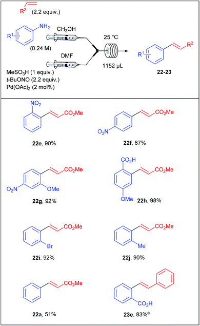
Surprised by the low yields obtained by Wirth and co-workers for several coupling products, Organ et al. assumed that they could originate from an unwanted competing hydrodediazotisation process.76 Thereby, the stability of diazonium salts was carefully monitored by 1H NMR and the authors clearly showed that the salts were stable in d4-MeOD at room temperature up to 48 hours while the unwanted dediazotisated by-product was observed after only 30 minutes at 0 °C in d7-DMF. Thereby, Organ et al. explained the moderate yields obtained by the group of Wirth by the extensive decomposition of the diazonium salt in DMF. With these preliminary results in hand, the authors designed a reaction setup consisting of two syringe pumps and containing the required material for the multicomponent process that occurred in a single reactor in a mixture of DMF and MeOH. Briefly, the first syringe pump was fed with a solution of aniline (1 equiv., 0.24 M) and olefin (2.2 equiv.) in MeOH while the second syringe pump was fed with a solution of methanesulfonic acid (1 equiv.), t-BuONO (2.2 equiv.) and palladium acetate (2 mol%) in DMF. The two resultant streams met into a mixing chamber and the reaction occurred into a coil reactor (1152 μL) at room temperature. Depending of the electronic nature of the anilines, the process was achieved with flow rates ranging from 3 to 12 μL min−1 corresponding to residence times of 6.4 and 1.6 hours respectively. The scope of the reaction included the coupling of electron-deficient and neutral anilines with methyl acrylate in modest to excellent yields (51–98%) while electron-rich anilines were overlooked (Table 15).
| a Pd(OAc)2 5 mol%. |
|---|
|
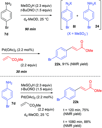
At the time Organ and co-workers published their remarkable results, our group was working on a significant different reaction setup using homogeneous and heterogeneous palladium catalysts. Indeed, while the group of Organ privileged a multicomponent approach, we opted from our side for a two-step diazotisation/cross-coupling sequence.77 Our strategy came from preliminary results conducted in batch on the diazotisation of 4-bromoaniline 7d into the corresponding diazonium salt 8l and its subsequent coupling with methyl acrylate (Scheme 17). We monitored this transformation, conducted in d4-MeOD at 25 °C, by 1H NMR and observed that the process carried out sequentially required a maximum of 120 min to reach >90% NMR yield of the coupling product 22k while the multicomponent approach required 1080 min (18 h) to attain a similar yield. From these results we concluded that a sequential strategy was at least 9 times faster than a multicomponent one.
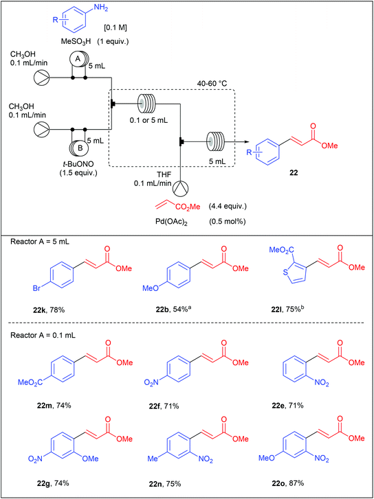
With these results in hand, we set a three-stream flow device up (Table 16). The injection loop A (5 mL) was filled with aniline (1 equiv., 0.1 M) and methanesulfonic acid (1 equiv.) in MeOH while the injection loop B (5 mL) was loaded with t-BuONO (1.5 equiv.) in MeOH. Pumping of each way was adjusted at 0.1 mL min−1 with two independent pumps. The two streams met at a T-shaped mixer (150 μL) and the resulting flow stream went through a PEEK coil reactor (0.1 or 5 mL) where the diazotisation occurred. Then, the stream containing the diazonium salt was telescoped in a second mixing chamber (150 μL) with a solution of palladium acetate (0.5 mol%) and methyl acrylate (4.4 equiv.) in THF coming from a third pump (0.1 mL min−1). The resulting mixture entered in a second PEEK coil reactor (5 mL) and the desired product was collected. Compared to the Organ's strategy, we obtained coupling products in slightly lower yields but a higher throughput was achieved thanks to lower residence times.
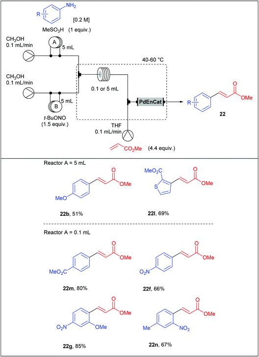
With the aim to develop a more sustainable process for the Heck–Matsuda reaction in flow, we used commercially available PdEnCat®30 as an immobilised palladium catalyst. Although the Heck–Matsuda reaction was already described with heterogeneous catalysts,78–86 this work was the first example of a heterogeneous Heck–Matsuda reaction in flow. The reaction setup, consisting of a three-stream flow device as depicted in Table 17, was similar to that designed for the homogeneous catalysis but the PEEK coil reactor B was replaced by an Omnifit-type glass column loaded with PdEnCat®30. Moreover, with this heterogeneous process, residence times were considerably lowered up to 225 seconds for the diazotisation/coupling sequence and a two-fold increased concentration of reagents was used, resulting in a drastically improved throughput. It should be noted that the concentration of palladium residues, measured by ICP-MS in the crude solution was in the range of 1 to 7 ppm, being in the acceptable limit for pharmaceutical agents.
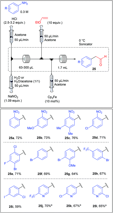
Beside Pd-catalysed reactions, the Meerwein arylation, involving the addition of aryl diazonium salts onto olefins via an aryl radical intermediate, recently rose up as a useful transformation for C–C bond formation.41,87 Following this growing interest, the group of Buchwald reported an iron-catalysed Meerwein arylation of vinyl ethyl ethers in flow leading to arylacetaldehyde.88 While the Meerwein arylation usually involves a copper-catalysed homolytic dediazotisation, S. L. Buchwald showed in a preliminary optimization studies that ferrocene displayed a remarkable activity for the studied transformation. The diazotisation/arylation sequence was carried out with a flow device assembled from syringe pumps as depicted in Table 18. A solution of aniline (1 equiv., 0.3 M) and hydrochloric acid (2.5–3.2 equiv.) in acetone was mixed with an aqueous solution of sodium nitrite (1.09 equiv.) in a T-shaped micromixer through two independent syringe pumps each adjusted at 50 μL min−1 before entering into a PFA tubing reactor (63–300 μL). The flow stream containing the diazonium salt was then mixed with a solution of ethyl vinyl ether (10 equiv., 50 μL min−1) in acetone and immediately after, this resulting mixture was straight mixed with a solution of ferrocene (10 mol%, 50 μL min−1). The reaction mixture was allowed to go through a PFA tubing reactor (1.7 mL) whereby the arylation step occurred. The scope of the reaction, evaluated on a collection of 24 anilines, revealed that the reaction was rather insensitive to the electronic nature of the anilines and was compatible with aminopyridines, giving arylacetaldehydes in fair to good yields (59–76%).
| a Isolated as the corresponding alcohol after reduction with of the crude solution with NaBH4. |
|---|
|
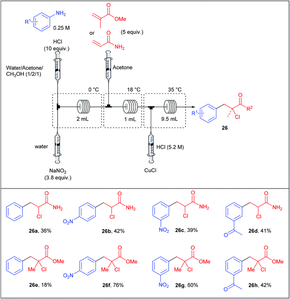
Following the work of Buchwald, the group of Kulkarni also contributed to the continuous-flow Meerwein arylation using methyl methacrylate and acrylamide as radical acceptors and copper(I) as catalyst.89 Similarly to Buchwald's approach, they opted for a reaction setup consisting of a four-stream flow device composed of four independent syringe pumps as depicted in Table 19. In preliminary studies, they carefully studied the effect of various parameters including the temperature of the three coil reactors, the catalyst nature, the residence time, as well as the concentrations of reagents and catalysts. In the optimised setup, the first stream containing a solution of aniline (1 equiv., 0.25 M) and concentrated HCl (10 equiv.) in a mixture of water–acetone–methanol (1/2/1) was mixed with a second stream containing an aqueous solution of NaNO2 (3.8 equiv.) in a micromixer immersed in an ice bath. The diazotisation occurred in a coil reactor (2 mL) and the resulting stream was telescoped with a solution of the olefin (5 equiv.) in acetone. For an efficient mixing the stream was passed into a 1 mL coil reactor held at 18 °C and then, a fourth stream containing HCl and CuCl was introduced through a micromixer, allowing the Meerwein arylation in a 9.5 mL coil reactor maintained at 35 °C. Unfortunately, the flow rate and the copper concentration were not mentioned by the authors. The arylation of acrylamide and methyl methacrylate were described on a representative set of four anilines with low to good yields (18–76%); methyl methacrylate being the radical acceptor that usually gave the higher yields. Interestingly, the arylation of acrylamide in batch mode systematically gave lower yields, highlighting the usefulness of continuous-flow processes.
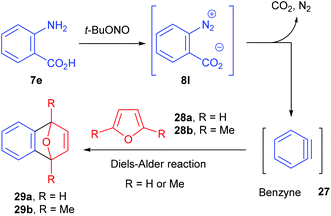
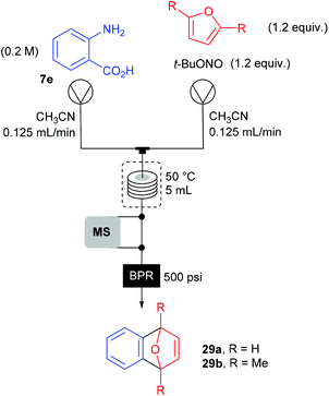
The group of Ley investigated the generation of benzyne 27 in flow from the corresponding benzene diazonium-2-carboxylate 8l and its subsequent reaction with furans 28a–b (Scheme 18).90 Usually, o-trimethylsilylphenyl triflate or 2-(trimethylsilyl)iodobenzene are traditional benzyne precursors because of their less hazardous properties that diazonium salts. However, a multistep synthesis of these compounds is needed prior to use whereas anthranilic acid 7e is commercially available. Thus, to address safety concerns associated with the use of diazonium salts, Ley and co-workers developed a flow approach monitored by mass spectrometry.
The use of an on-line miniature ESI mass spectrometer coupled to a two-stream flow device allows the observation of reactive intermediates and competing reaction paths. Moreover, this analytical technique proved to be useful to optimize reaction conditions (reactor temperature and residence time) thanks to peak height trends on mass spectrum. An off-line LC/MS analysis was also used in order to corroborate the on-line ESI-MS data. At an early stage of their work, the diazonium conversion was not complete and the ESI-MS were able to analyze diazonium and by-products ion peaks.
The flow setup consisted of two pumps working at 0.125 mL min−1 each (Scheme 19). The first one was fed with a solution of anthranilic acid (1 equiv., 0.2 M) in CH3CN while the second one was fed with a solution of furan or 1,5-dimethylfuran (1.2 equiv.) and t-BuONO (1.2 equiv.) in CH3CN. The two flow streams met at a T-mixing piece and went through a 5 mL coil reactor heated at 50 °C and pressurised at 34 bar. For safety reasons, the reactor outlet went to a saturated aqueous Na2S2O3 solution to quench unreacted hazardous species. Unfortunately, authors did not mention the yields obtained for both transformations.
6. Grafting reactions of carbon based nanomaterials
One of the main drawbacks of flow chemistry is the recurrent clogging issues occurring with highly crystalline or poorly soluble reagents.91 This is one of the main reason for which multi-physical composition of reagents are usually unsuitable for flow chemistry. To tackle this drawback, the use of specifically designed reactors and conditions that allows a high dispersion of the material in the solvent has provided successful results.92–102Gasparini, Maggini and co-workers have described the functionalisation of single wall carbon nanotubes (SWNTs) with 4-methoxybenzenediazonium salt 8h using a Coflore® agitated cell reactor allowing better heat and mass transfer with mixtures containing gaseous, liquids and solids compared to traditional micro-reactors.103 The 20 mL Coflore® reactor is composed of ten reaction cells containing freely moving hastelloy agitators and connected by channels of 4 mm in diameter (Fig. 1).
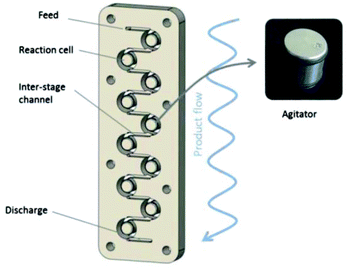 | ||
| Fig. 1 Schematic representation of the Coflore® agitated cell reactor. Reprinted with permission from ref. 103, copyright 2012 Tekno Scienze Publisher. | ||
The reactor was coupled to the main flow line containing a mixture of pristine SWNTs, 4-methoxyaniline and i-pentylnitrite introduced through an injection loop (Fig. 2). It is not clear whatever DMF or 1-cyclohexylpyrrolid-2-one was used as the solvent since both are mentioned in the article. Anyway, optimization studies showed that the optimal grafting conditions were reached at a low flow rate (0.12 mL min−1), corresponding to a residence time of 120 min, and with an excess of the diazonium salt (5 equiv.). The degree of functionalisation of the SWNTs in these conditions, expressed as the ratio between the mole of functional group and the moles of carbon in the tubes, reached 4.10−2, corresponding to 1 functional group every 25 carbon atoms. The advantages of flow chemistry compared to a standard flask synthesis was evidenced by a two-fold higher productivity reaching 1 mg h−1 mL−1 thanks to a lower reaction time (30–120 min vs. 15 h).
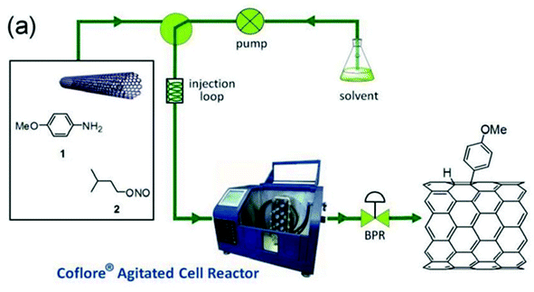 | ||
| Fig. 2 Functionalisation of SWNTs by diazonium salts enabled by flow chemistry. Reprinted with permission from ref. 103, copyright 2012 Tekno Scienze Publisher. | ||
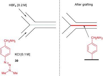
Another successful application of flow chemistry consists in patterning narrow lines of metals, polymers, and inorganic crystals onto various support at the interfacial mixing region of a two-stream laminar flow.104 In this event, Downard and co-workers described the surface patterning of a pyrolyzed photoresist film with aryl diazonium salts using a two-stream flow device.105 The setup consisted in 2 inlets respectively containing a solution of the triazene 30 in aqueous KCl (0.1 M) for the first one, while an aqueous solution of 40% HBF4 (0.2 M) was introduced through the second inlet (Fig. 3).
The course of the stream was controlled by a poly(dimethylsiloxane) (PDMS) mold of 100 μM in width, 50 μM in height and 12 mm in length, that was sealed onto the pyrolyzed photoresist film. Impressively, the functionalisation of the carbon surface occurred at the interface of the two solutions, drawing a line of grafted film significantly narrower than the microchannel. The line width of the grafted film depends on the flow rate since the effects of diffusion increase as the contact time between the two solutions become more important. For instance, at 0.2 mL min−1 the line width is approximately 15 μM near the inlet and progressively broadens down the channel with a very rough grafted film ranging from 5–250 nm in height. As expected, at a ten-fold higher flow rate, the line is only 800 nm in width and 2.4 nm in height (Fig. 4). The grafted film can be easily recovered by removing the mold and washing the surface with water.
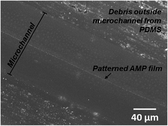 | ||
| Fig. 4 Patterning of pyrolyzed photoresist film using a two-stream flow setup. Reprinted with permission from ref. 105, copyright 2013 Wiley-VCH Verlag GmbH & Co. KGaA, Weinheim. | ||
7. Conclusion
There are not so much species that display a so broad reactivity than diazonium salts in the tool box of organic chemists. However, the hazardous behavior of diazonium salts, heaping opprobrium on this class of extremely useful reagent, has severely limited their use. Though, chemists have many tools available to predict or evaluate their stability. The emergence of flow chemistry as an enabling technology, ideally suited for the handling of hazardous species, is largely participating in the recent prominence of diazonium salts. Indeed, with specifically designed flow devices, the isolation of diazonium salts is not required anymore. Moreover, the small size of reactors and the facile automation of devices significantly enhance safety since the continuous flow can be stopped at any time in case of the emergence of an uncontrolled process. In this review we carefully examined the various situations in which diazonium salts have been successfully used in continuous flow processes. Especially, we took a close look to the flow setup so that this contribution can serve as a useful textbook for chemists not well versed with flow chemistry. We believe that these pioneering studies will further inspire organic and material chemists in designing chemical routes involving flow chemistry and diazonium salts.Acknowledgements
We gratefully acknowledge the University of Nantes, the “Centre National de la Recherche Scientifique” (CNRS), the “Région Pays de la Loire” in the framework of a “recrutement sur poste stratégique”. F.-X.F. is a member of the “Institut Universitaire de France” (IUF).Notes and references
- S. Patai, in The Chemistry of Diazonium and Diazo Groups, John Wiley & Sons Ltd, 1978 Search PubMed.
- Z. Wang, in Comprehensive Organic Name Reactions and Reagents, John Wiley & Sons, Inc., 2010 Search PubMed.
- C. Galli, Chem. Rev., 1988, 88, 765–792 CrossRef CAS.
- F. Mo, G. Dong, Y. Zhang and J. Wang, Org. Biomol. Chem., 2013, 11, 1582–1593 CAS.
- L. He, G. Qiu, Y. Gao and J. Wu, Org. Biomol. Chem., 2014, 12, 6965–6971 CAS.
- F. Hamon, F. Djedaini-Pilard, F. Barbot and C. Len, Tetrahedron, 2009, 65, 10105–10123 CrossRef CAS.
- E. Merino, Chem. Soc. Rev., 2011, 40, 3835–3853 RSC.
- V. D. Filimonov, M. Trusova, P. Postnikov, E. A. Krasnokutskaya, Y. M. Lee, H. Y. Hwang, H. Kim and K.-W. Chi, Org. Lett., 2008, 10, 3961–3964 CrossRef CAS PubMed.
- P. Baumeister, W. Meyer, K. Oertle, G. Seifert and H. Steiner, Chimia, 1997, 51, 144–146 CAS.
- M. A. Nielsen, M. K. Nielsen and T. Pittelkow, Org. Process Res. Dev., 2004, 8, 1059–1064 CrossRef CAS.
- C. Molinaro, J. Mowat, F. Gosselin, P. D. O'Shea, J.-F. Marcoux, R. Angelaud and I. W. Davies, J. Org. Chem., 2007, 72, 1856–1858 CrossRef CAS PubMed.
- B. Li, D. Widlicka, S. Boucher, C. Hayward, J. Lucas, J. C. Murray, B. T. O'Neil, D. Pfisterer, L. Samp, J. VanAlsten, Y. Xiang and J. Young, Org. Process Res. Dev., 2012, 16, 2031–2035 CrossRef CAS.
- Z. Yu, Y. Lv and C. Yu, Org. Process Res. Dev., 2012, 16, 1669–1672 CrossRef CAS.
- A. P. Colleville, R. A. J. Horan and N. C. O. Tomkinson, Org. Process Res. Dev., 2014, 18, 1128–1136 CrossRef CAS.
- F. Le Callonnec, E. Fouquet and F.-X. Felpin, Org. Lett., 2011, 13, 2646–2649 CrossRef CAS PubMed.
- N. Susperregui, K. Miqueu, J.-M. Sotiropoulos, F. Le Callonnec, E. Fouquet and F.-X. Felpin, Chem. – Eur. J., 2012, 18, 7210–7218 CrossRef CAS PubMed.
- N. Oger, F. Le Callonnec, D. Jacquemin, E. Fouquet, E. Le Grognec and F.-X. Felpin, Adv. Synth. Catal., 2014, 356, 1065–1071 CrossRef CAS.
- A. Honraedt, M.-A. Raux, E. Le Grognec, D. Jacquemin and F.-X. Felpin, Chem. Commun., 2014, 50, 5236–5238 RSC.
- N. Oger, M. d'Halluin, E. Le Grognec and F.-X. Felpin, Org. Process Res. Dev., 2014, 18, 1786–1801 CrossRef CAS.
- G. Jas and A. Kirschning, Chem. – Eur. J., 2003, 9, 5708–5723 CrossRef CAS PubMed.
- A. Kirschning, W. Solodenko and K. Mennecke, Chem. – Eur. J., 2006, 12, 5972–5990 CrossRef CAS PubMed.
- M. Baumann, I. Baxendale and S. Ley, Mol. Diversity, 2011, 15, 613–630 CrossRef CAS PubMed.
- M. O'Brien, R. Denton and S. V. Ley, Synthesis, 2011, 1157–1192 Search PubMed.
- J. Wegner, S. Ceylan and A. Kirschning, Chem. Commun., 2011, 47, 4583–4592 RSC.
- T. Chinnusamy, S. Yudha, M. Hager, P. Kreitmeier and O. Reiser, ChemSusChem, 2012, 5, 247–255 CrossRef CAS PubMed.
- S. V. Ley, Chem. Rec., 2012, 12, 378–390 CrossRef CAS PubMed.
- H. Amii, A. Nagaki and J.-i. Yoshida, Beilstein J. Org. Chem., 2013, 9, 2793–2802 CrossRef PubMed.
- L. N. Protasova, M. Bulut, D. Ormerod, A. Buekenhoudt, J. Berton and C. V. Stevens, Org. Process Res. Dev., 2013, 17, 760–791 CrossRef CAS.
- A. Puglisi, M. Benaglia and V. Chiroli, Green Chem., 2013, 15, 1790–1813 RSC.
- S. Fuse, Y. Mifune, N. Tanabe and T. Takahashi, Synlett, 2014, 2087–2092 CrossRef CAS.
- P. Plouffe, A. Macchi and D. M. Roberge, Org. Process Res. Dev., 2014, 18, 1286–1294 CrossRef CAS.
- T. Rodrigues, P. Schneider and G. Schneider, Angew. Chem., Int. Ed., 2014, 53, 5750–5758 CrossRef CAS PubMed.
- L. Vaccaro, D. Lanari, A. Marrocchi and G. Strappaveccia, Green Chem., 2014, 16, 3680–3704 RSC.
- T. Noel and S. L. Buchwald, Chem. Soc. Rev., 2011, 40, 5010–5029 RSC.
- G. Sipos, V. Gyollai, T. Sipőcz, G. Dormán, L. Kocsis, R. Jones and F. Darvas, J. Flow Chem., 2013, 3, 51–58 CrossRef CAS.
- P. Poechlauer, J. Colberg, E. Fisher, M. Jansen, M. D. Johnson, S. G. Koenig, M. Lawler, T. Laporte, J. Manley, B. Martin and A. O'Kearney-McMullan, Org. Process Res. Dev., 2013, 17, 1472–1478 CrossRef CAS.
- A. Roglans, A. Pla-Quintana and M. Moreno-Mañas, Chem. Rev., 2006, 106, 4622–4643 CrossRef CAS PubMed.
- H. Bonin, E. Fouquet and F.-X. Felpin, Adv. Synth. Catal., 2011, 353, 3063–3084 CrossRef CAS.
- F.-X. Felpin, L. Nassar-Hardy, F. Le Callonnec and E. Fouquet, Tetrahedron, 2011, 67, 2815–2831 CrossRef CAS.
- J. G. Taylor, A. V. Moro and C. R. D. Correia, Eur. J. Org. Chem., 2011, 1403–1428 CrossRef CAS.
- D. P. Hari and B. König, Angew. Chem., Int. Ed., 2013, 52, 4734–4743 CrossRef CAS PubMed.
- B. J. Deadman, S. G. Collins and A. R. Maguire, Chem. – Eur. J., 2015, 21, 2298–2308 CrossRef CAS PubMed.
- P. Griess, Liebigs Ann. Chem., 1858, 106, 123–125 CrossRef.
- P. F. Gordon and P. Gregory, Organic Chemistry in Colour, Springer, New York, 1983 Search PubMed.
- H. Zollinger, Color Chemistry: Syntheses, Properties and Applications of Organic Dyes and Pigments, VCH, Weinheim, 1987 Search PubMed.
- K. Hunger and W. Herbst, in Ullmann's Encyclopedia of Industrial Chemistry, Wiley-VCH Verlag GmbH & Co. KGaA, 2000 Search PubMed.
- K. Hunger, P. Mischke, W. Rieper, R. Raue, K. Kunde and A. Engel, in Ullmann's Encyclopedia of Industrial Chemistry, Wiley-VCH Verlag GmbH & Co. KGaA, 2000 Search PubMed.
- K. Hunger, Industrial Dyes: Chemistry, Properties, Applications, Wiley-VCH, Weinheim, 2003 Search PubMed.
- R. C. R. Wootton, R. Fortt and A. J. de Mello, Lab Chip, 2002, 2, 5–7 RSC.
- M. Chen and S. L. Buchwald, Angew. Chem., Int. Ed., 2013, 52, 4247–4250 CrossRef CAS PubMed.
- H.-G. Lee, J.-E. Won, M.-J. Kim, S.-E. Park, K.-J. Jung, B. R. Kim, S.-G. Lee and Y.-J. Yoon, J. Org. Chem., 2009, 74, 5675–5678 CrossRef CAS PubMed.
- C. A. Baxter, E. Cleator, K. M. J. Brands, J. S. Edwards, R. A. Reamer, F. J. Sheen, G. W. Stewart, N. A. Strotman and D. J. Wallace, Org. Process Res. Dev., 2011, 15, 367–375 CrossRef CAS.
- M. Taillefer, N. Xia and A. Ouali, Angew. Chem., Int. Ed., 2007, 46, 934–936 CrossRef CAS PubMed.
- J. Jacq and P. Pasau, Chem. – Eur. J., 2014, 20, 12223–12233 CrossRef CAS PubMed.
- N. P. Bel'skaya, M. A. Demina, S. G. Sapognikova, Z. J. Fan, H. K. Zhang, W. Dehaen and V. A. Bakulev, ARKIVOC, 2008, 9–21 Search PubMed.
- L. Knorr, Ber. Dtsch. Chem. Ges., 1883, 16, 2597–2599 CrossRef.
- R. Fortt, R. C. R. Wootton and A. J. de Mello, Org. Process Res. Dev., 2003, 7, 762–768 CrossRef CAS.
- G. Balz and G. Schiemann, Ber. Dtsch. Chem. Ges., 1927, 60, 1186–1190 CrossRef.
- Z.-Q. Yu, Y.-W. Lv, C.-M. Yu and W.-K. Su, Tetrahedron Lett., 2013, 54, 1261–1263 CrossRef CAS.
- L. Malet-Sanz, J. Madrzak, S. V. Ley and I. R. Baxendale, Org. Biomol. Chem., 2010, 8, 5324–5332 CAS.
- H. Meerwein, G. Dittmar, R. Göllner, K. Hafner, F. Mensch and O. Steinfort, Chem. Ber., 1957, 90, 841–852 CrossRef CAS.
- O. Stadler, Ber. Dtsch. Chem. Ges., 1884, 17, 2075–2081 CrossRef CAS.
- J. H. Ziegler, Ber. Dtsch. Chem. Ges., 1890, 23, 2469–2472 CrossRef CAS.
- X. Wang, G. D. Cuny and T. Noël, Angew. Chem., Int. Ed., 2013, 52, 7860–7864 CrossRef CAS PubMed.
- R. J. Ingham, C. Battilocchio, J. M. Hawkins and S. V. Ley, Beilstein J. Org. Chem., 2014, 10, 641–652 CrossRef PubMed.
- D. X. Hu, M. O'Brien and S. V. Ley, Org. Lett., 2012, 14, 4246–4249 CrossRef CAS PubMed.
- E. F. V. Scriven and K. Turnbull, Chem. Rev., 1988, 88, 297–368 CrossRef CAS.
- S. Bräse, C. Gil, K. Knepper and V. Zimmermann, Angew. Chem., Int. Ed., 2005, 44, 5188–5240 CrossRef PubMed.
- S. Chiba, Synlett, 2012, 21–44 CrossRef CAS.
- F. Stazi, D. Cancogni, L. Turco, P. Westerduin and S. Bacchi, Tetrahedron Lett., 2010, 51, 5385–5387 CrossRef CAS.
- C. J. Smith, N. Nikbin, S. V. Ley, H. Lange and I. R. Baxendale, Org. Biomol. Chem., 2011, 9, 1938–1947 CAS.
- C. J. Smith, C. D. Smith, N. Nikbin, S. V. Ley and I. R. Baxendale, Org. Biomol. Chem., 2011, 9, 1927–1937 CAS.
- P. Sharma, A. D. Moorhouse and J. E. Moses, Synlett, 2011, 2384–2386 CAS.
- C. Spiteri and J. E. Moses, Synlett, 2012, 1546–1548 CAS.
- B. Ahmed-Omer, D. A. Barrow and T. Wirth, Tetrahedron Lett., 2009, 50, 3352–3355 CrossRef CAS.
- K. S. Nalivela, M. Tilley, M. A. McGuire and M. G. Organ, Chem. – Eur. J., 2014, 20, 6603–6607 CrossRef CAS PubMed.
- N. Oger, E. Le Grognec and F.-X. Felpin, J. Org. Chem., 2014, 79, 8255–8262 CrossRef CAS PubMed.
- M. Beller and K. Kühlein, Synlett, 1995, 442 Search PubMed.
- H. Brunner, N. Le Cousturier de Courcy and J.-P. Genêt, Tetrahedron Lett., 1999, 40, 4815–4818 CrossRef CAS.
- F.-X. Felpin, E. Fouquet and C. Zakri, Adv. Synth. Catal., 2008, 350, 2559–2565 CrossRef CAS.
- F.-X. Felpin, J. Coste, C. Zakri and E. Fouquet, Chem. – Eur. J., 2009, 15, 7238–7245 CrossRef CAS PubMed.
- F.-X. Felpin, O. Ibarguren, L. Nassar-Hardy and E. Fouquet, J. Org. Chem., 2009, 74, 1349–1352 CrossRef CAS PubMed.
- O. Ibarguren, C. Zakri, E. Fouquet and F.-X. Felpin, Tetrahedron Lett., 2009, 50, 5071–5074 CrossRef CAS.
- M. Gholinejad, Appl. Organomet. Chem., 2013, 27, 19–22 CrossRef CAS.
- X. Li, L.-C. Wang, H.-H. Chang, C.-X. Zhang and W.-L. Wei, Appl. Catal., A, 2013, 462–463, 15–22 CrossRef CAS.
- A. S. Singh, S. S. Shendage and J. M. Nagarkar, Tetrahedron Lett., 2013, 54, 6319–6323 CrossRef CAS.
- H. Bonin, M. Sauthier and F.-X. Felpin, Adv. Synth. Catal., 2014, 356, 645–671 CrossRef CAS.
- N. Chernyak and S. L. Buchwald, J. Am. Chem. Soc., 2012, 134, 12466–12469 CrossRef CAS PubMed.
- V. Bhaya, R. Joshi and A. Kulkarni, J. Flow Chem., 2014, 4, 210–215 Search PubMed.
- D. L. Browne, S. Wright, B. J. Deadman, S. Dunnage, I. R. Baxendale, R. M. Turner and S. V. Ley, Rapid Commun. Mass Spectrom., 2012, 26, 1999–2010 CrossRef CAS PubMed.
- R. L. Hartman, Org. Process Res. Dev., 2012, 16, 870–887 CrossRef CAS.
- P. Salice, P. Maity, E. Rossi, T. Carofiglio, E. Menna and M. Maggini, Chem. Commun., 2011, 47, 9092–9094 RSC.
- D. L. Browne, B. J. Deadman, R. Ashe, I. R. Baxendale and S. V. Ley, Org. Process Res. Dev., 2011, 15, 693–697 CrossRef CAS.
- C. B. Kelly, C. Lee and N. E. Leadbeater, Tetrahedron Lett., 2011, 52, 263–265 CrossRef CAS.
- J. r. Sedelmeier, S. V. Ley, I. R. Baxendale and M. Baumann, Org. Lett., 2010, 12, 3618–3621 CrossRef CAS PubMed.
- T. Horie, M. Sumino, T. Tanaka, Y. Matsushita, T. Ichimura and J.-i. Yoshida, Org. Process Res. Dev., 2010, 14, 405–410 CrossRef CAS.
- R. L. Hartman, J. R. Naber, N. Zaborenko, S. L. Buchwald and K. F. Jensen, Org. Process Res. Dev., 2010, 14, 1347–1357 CrossRef CAS.
- M. Takagi, T. Maki, M. Miyahara and K. Mae, Chem. Eng. J., 2004, 101, 269–276 CrossRef CAS.
- C. Amador, A. Gavriilidis and P. Angeli, Chem. Eng. J., 2004, 101, 379–390 CrossRef CAS.
- N. Kockmann, J. Kastner and P. Woias, Chem. Eng. J., 2008, 135(Supplement 1), S110–S116 CrossRef CAS.
- S. L. Poe, M. A. Cummings, M. P. Haaf and D. T. McQuade, Angew. Chem., Int. Ed., 2006, 45, 1544–1548 CrossRef CAS PubMed.
- B. Buisson, S. Donegan, D. Wray, A. Parracho, J. Gamble, P. Caze, J. Jorda and C. Guermeur, Chim. Oggi-Chem. Today, 2009, 27, 12–16 CAS.
- P. Salice, D. Fenaroli, C. C. De Filippo, E. Menna, G. Gasparini and M. Maggini, Chem. Today, 2012, 30, 37–39 CAS.
- P. J. A. Kenis, R. F. Ismagilov and G. M. Whitesides, Science, 1999, 285, 83–85 CrossRef CAS PubMed.
- A. J. Gross, V. Nock, M. I. J. Polson, M. M. Alkaisi and A. J. Downard, Angew. Chem., Int. Ed., 2013, 52, 10261–10264 CrossRef CAS PubMed.
| This journal is © the Partner Organisations 2015 |


