Bio-ink for on-demand printing of living cells†
Cameron J.
Ferris
ab,
Kerry J.
Gilmore
a,
Stephen
Beirne
a,
Donald
McCallum
ab,
Gordon G.
Wallace
*a and
Marc
in het Panhuis
*ab
aIntelligent Polymer Research Institute, ARC Centre of Excellence for Electromaterials Science, AIIM Facility, University of Wollongong, Wollongong, NSW 2522, Australia. E-mail: gwallace@uow.edu.au; Tel: +61 24221 3155
bSoft Materials Group, School of Chemistry, University of Wollongong, Wollongong, NSW 2522, Australia. E-mail: panhuis@uow.edu.au; Tel: +61 24221 3155
First published on 5th November 2012
Abstract
Drop-on-demand bioprinting allows the controlled placement of living cells, and will benefit research in the fields of tissue engineering, drug screening and toxicology. We show that a bio-ink based on a novel microgel suspension in a surfactant-containing tissue culture medium can be used to reproducibly print several different cell types, from two different commercially available drop-on-demand printing systems, over long printing periods. The bio-ink maintains a stable cell suspension, preventing the settling and aggregation of cells that usually impedes cell printing, whilst meeting the stringent fluid property requirements needed to enable printing even from many-nozzle commercial inkjet print heads. This innovation in printing technology may pave the way for the biofabrication of multi-cellular structures and functional tissue.
Introduction
Bioprinting is an emerging technology that highlights a growing trend in the fusion of biology and engineering. The ability to design and fabricate complex structures by printing living cells, biomaterials and other biological molecules is crucial to the success of tissue engineering,1,2 and enables new possibilities in drug screening and toxicology.3,4 In the continuing quest to engineer functional tissues and organs, bioprinting could allow the fabrication of multi-cellular constructs where cell–cell and cell–material interactions mimic the physiological environment and where cellular responses to stimuli are more reflective of those found in vivo.The suite of bioprinting techniques that allow the controlled deposition of living cells has expanded to include extrusion printing5,6 and laser printing,7,8 as well as drop-on-demand approaches like microvalve printing9,10 and inkjet printing.11–14 Drop-on-demand techniques are attractive due to their relative simplicity and capability for precise non-contact deposition, yet have been hindered by some critical limitations. Cell settling and aggregation within printer reservoirs obstructs nozzles and leads to non-uniform cell distribution so that cell output significantly decreases or fails when printing over long time periods.15 Gentle agitation of inkjet print heads and microvalves can reduce cell settling16,17 and the addition of ethylenediaminetetraacetic acid limits aggregation,18 but these strategies are only partly effective and can be detrimental to cell viability. Printing cells in high viscosity collagen solutions can retard settling, although this approach is limited to specialized printing systems.9
Inkjet printing presents additional challenges as the ink must meet stringent fluid property requirements (e.g. viscosity and surface tension) for efficient deposition.19 Currently, non-ideal ink formulations have been printed using single- or few-nozzle devices,11,13,20,21 or outdated thermal inkjet heads.12,14,22–24 Piezoelectric inkjet print-heads with multiple nozzles are the current standard for high-end printing applications, and could allow for higher throughput and fabrication of larger cellular constructs. Rather than developing bio-inks that are suitable for use in these systems, bio-ink design has focused on two-component fast-gelling reactive schemes. Cells have been mixed with alginate and printed into cross-linking Ca2+ solutions,20,25 or mixed with Ca2+ and printed into either alginate or alginate/collagen solutions.26 Similar approaches have utilized the fibrin/thrombin reaction22,23 or photo-polymerisable inks.24 However, these printed environments are not suitable for all cell types and applications. To deliver on the initial promise of drop-on-demand cell printing, we must develop smarter bio-inks that are tailored to satisfy the seemingly disparate demands of printability and cell function, and are amenable to printing using standard hardware.
Here, we report on the development of a general purpose bio-ink that addresses these challenges to allow facile cell deposition by drop-on-demand printing using both a commercial microvalve deposition system, and many-nozzle piezoelectric inkjet print heads.
Experimental
Bio-ink
Endotoxin-free low-acyl gellan gum (Gelzan CM, a gift from CP Kelco) was dissolved in hot (80 °C) Milli-Q water (resistivity 18.2 MΩ cm) at 1% (w/v) by stirring for 1–2 h. This hot solution was combined with heated (80 °C) Milli-Q and 2× concentrated Dulbecco's Modified Eagles Medium (DMEM, Invitrogen) to produce a range of gellan gum concentrations in 1× DMEM. The mixture was sheared using a vortex mixer while cooling to 25 °C to create a microgel suspension, i.e. the bio-ink. The surfactant-containing bio-inks were prepared through addition of Poloxamer 188 surfactant (Lutrol® F68, Sigma) and/or fluorosurfactant (Novec® FC-4430, 3M) solutions to the microgel suspension. All bio-inks were prepared under aseptic conditions.Cell culture
C2C12 (CRL-1772), PC12 (CRL-1721) and L929 (CCL-1) murine cell lines were obtained from ATCC. C2C12 and L929 cells were maintained in DMEM (Invitrogen) supplemented with 10% fetal bovine serum (FBS, Invitrogen), while PC12 cells were maintained in DMEM with 10% fetal bovine serum and 5% horse serum (HS, Sigma). Cells were cultured at 37 °C in a humidified incubator with 5% CO2 and passaged every 2–3 days.Bio-ink characterization
Rheology of the bio-ink was characterized using a controlled-stress ARG2 rheometer (TA Instruments), using a sandblasted 40 mm parallel plate geometry with a measurement gap of 0.5 mm and Peltier plate thermal control. A solvent trap was used to prevent evaporation of water during measurements. After loading, samples were subjected to 30 s pre-shear at 500 s−1 followed by 1 min equilibration before measurement. Shear-dependent viscosity was measured by a stepped ramp of shear rate from 1–1000 s−1. Each shear rate (10 points per decade) was held for 20 s, and the viscosity over the last 10 s was averaged. Apparent yield stress was measured by a continuous ramp of shear stress from 0–2 Pa over 5 min.Constitutive modelling was facilitated by Rheology Advantage data analysis software (TA Instruments). Silicone oil standards (Scientific Polymer Products) were used to validate experimental conditions. Surface tension was measured using a Dataphysics OCA contact angle system with SCA 20 software.
The structure of the bio-ink was visualized by negative staining with a pigmented ink (Derivan Ink, black) that was excluded from microgel particles. Derivan Ink (1![[thin space (1/6-em)]](https://www.rsc.org/images/entities/char_2009.gif) :5) was added to the bio-ink, 20 μL, and was immediately placed on a glass slide and cover-slipped prior to imaging.
:5) was added to the bio-ink, 20 μL, and was immediately placed on a glass slide and cover-slipped prior to imaging.
The ability of the bio-ink to maintain cells in suspension was determined by suspending cells at 1–6 × 10⁶ cells mL−1 in the ink or in serum-free DMEM as the control. 100 μL aliquots of both suspensions were added to 96-well plates, and the base of each well was imaged over time. Image J software was used to count the number of cells in a defined area of the wells at each time-point, allowing the number of settled cells to be plotted as a function of time.
Printer design
Microvalve cell printing was facilitated through a Deerac™ GX1 liquid handling system (Labcyte Inc.), which dispenses droplets using a magnetic feedback-controlled microvalve. Cells were inkjet printed using a custom-built inkjet printing system with Xaar-126 piezoelectric inkjet print heads (Xaar®, see the ESI†). Both printers were housed in a bio-safety cabinet and sterilised regularly using 70% ethanol and UV light.Cell printing
For microvalve printing, C2C12 cells were suspended in the bio-ink (without added surfactants) at 2 × 10⁵–2 × 10⁶ cells per mL and aspirated into the Deerac™ GX1 nozzle reservoir. Patterns were designed using accompanying software (Spot Station/Plate Designer). For analysis of cell viability and proliferation, 50 drops were printed into 100 μL of the cell culture media supplemented with 100 units per mL penicillin and 100 μg mL−1 streptomycin (Pen/Strep, Gibco).For inkjet printing, cells (C2C12 or PC12) were suspended in the surfactant-containing bio-ink at 1–6 × 10⁶ cells per mL, and loaded into the print heads by aspirating through the nozzle plate. Patterns were designed in Microsoft Paint and loaded into Xaar XUSB software.
For analysis of cell viability, proliferation and differentiation, rectangular patterns (25 × 50 drops) were printed into supplemented media as above. This media was contained within thin (1 mm) PDMS wells (Fig. S2†), and subsequently transferred to a 96-well plate for further culture and analysis.
For analysis of the cell/drop distribution, cells were printed directly onto glass slides and allowed to dry. The number of cells in each drop, or the number of cells in a printed pattern, was then counted manually or imaged using a Zeiss Axiovert 40 CFL inverted fluorescence microscope (Carl Zeis AG) and counted using Image Pro software.
For patterning experiments, cells were inkjet printed onto collagen bio-paper. Collagen I (rat tail, 5 mg mL−1, Invitrogen) was sonicated for 5 min on ice, combined with cold 5× concentrated DMEM to a final concentration of 4 mg mL−1 and neutralised with 0.1 M NaOH. The cold collagen solution was pipetted into 0.5 mm thick PDMS wells and polymerized for 2 h at 37 °C. 1 mm thick PDMS wells were then placed on top of the existing PDMS to create a reservoir (Fig. S2†). Collagen bio-papers were soaked in cell culture media supplemented with Pen/Strep for 1–2 h, and excess medium was removed prior to cell printing. Cell patterns were printed onto collagen bio-papers, and incubated at 37 °C for 1 h to allow cells to attach prior to further addition of the culture medium. In dual cell printing experiments, cells were stained prior to printing with CellTracker™ Probes (Molecular Probes, Invitrogen). C2C12 cells were stained with CellTracker™ Red CMPTX (20 μM) and PC12 cells were stained with CellTracker™ Green CMFDA (20 μM), following the manufacturer’s protocols.
Details on methods for cell viability, cell proliferation and differentiation and immunostaining can be found in the ESI.†
Results and discussion
We prepared bio-inks by producing microgels (a dispersed phase of discrete polymeric gel particles) in standard cell culture media (DMEM) using the biopolymer gellan gum. This linear anionic polysaccharide has found widespread use in the food and cosmetic industries as a gelling and stabilizing agent,27 and more recently as a material for tissue engineering applications.28–30The choice of gellan gum over a more widely employed polysaccharide such as alginate is justified as follows. Gellan gum is a linear anionic polysaccharide similar to alginate.31 The key difference between these two biopolymers is their gelation mechanism. Association of alginate chains during gelation occurs according to an ‘egg-box’ model,31 where divalent cations bind pairs of polymer chains through the formation of stable junction zones. In contrast, gelation of gellan gum is preceded by a conformational transition from coil to double helix, and association of these helices in junction zones is facilitated through either monovalent or divalent cations.32 Consequently, gellan gum hydrogels may be formed at lower concentrations of divalent cations than those required for alginate. Gellan gum can even form gels in the presence of monovalent cations alone.
Gellan gum is particularly attractive for its ability to form microgels at low concentrations,33 which allows the mass content of the bio-ink to be kept at low levels. Furthermore, the concentration window to form microgels is much broader for gellan gum compared to that of alginate.34 A range of gellan gum concentrations was investigated and 0.05% (w/v) was found to be the lowest concentration at which microgels form (Fig. S4†). Imaging of the bio-ink structure at this concentration clearly revealed an associated network of elongated microgel particles (Fig. 1a). This tenuous network structure imparted pseudo-plastic properties that we elucidated by rheological measurements of both the apparent yield stress and the apparent viscosity as a function of shear rate. The bio-ink exhibited an apparent yield stress of ∼30 mPa (Fig. S3a†) followed by shear-thinning flow behaviour that showed good agreement with constitutive modeling (Fig. S3b†).
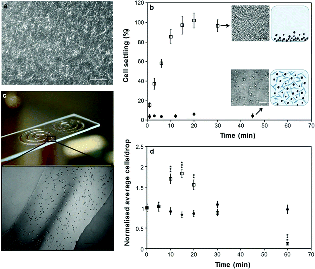 | ||
| Fig. 1 Bio-ink structure and cell settling. (a) Structure of the bio-ink visualized by staining with Derivan ink and imaged by phase-contrast microscopy. Scale bar 200 μm. (b) Cell settling (percentage of cells on the base of a 96 well plate) as a function of time for C2C12 cells suspended at 1 × 10⁶ cells per mL in DMEM (open squares) or bio-ink (filled circles). Error bars represent one standard deviation from the mean. Insets show the base of well plates at indicated time points (scale bars 100 μm) and cartoons depicting the ability of the microgel suspension to keep cells in suspension. (c) Spiral patterns of C2C12 cells suspended in bio-ink and deposited on a glass slide by microvalve printing. Scale bar 500 μm. (d) Average number of cells per drop over time, normalized to the number of cells in initial drops, for C2C12 cells suspended at 2 × 10⁵ cells per mL in DMEM (open squares) or bio-ink (filled circles) and deposited by microvalve printing. Error bars represent one standard error of the mean (n = 10). A statistically significant difference (compared to t = 0 min) was assessed by unpaired Student's t-test and reported with 99% (**) or 99.9% confidence (***). | ||
Importantly, these properties are suitable to satisfy the dual aims of cell-suspending ability and printability. Cell settling in a fluid can be described by Stoke's law,15 which defines a minimum yield stress of ∼5 mPa for zero settling velocity. Thus the yield stress of the bio-ink is, theoretically, sufficient to keep the cells suspended. Additionally, the shear-thinning behaviour presents a high viscosity to settling cells (shear rates <10 s−1) to maintain suspensions, and a low viscosity during droplet ejection (shear rates >103 s−1) to aid printability. To confirm this we performed cell settling tests and found that cells in the bio-ink remained suspended with no sign of aggregation, whereas cells suspended in DMEM alone completely settled to the base of a 96-well plate within 15 min (Fig. 1b). The consequences of this for drop-on-demand cell printing were directly demonstrated by analyzing cell output over time by microvalve deposition. With DMEM alone, cell output showed significant variation with a sharp peak due to cell settling, followed by a steady decrease during the deposition of cell-depleted media, whilst cell output was steady over 1 h of printing with the bio-ink (Fig. 1d). This allowed the deposition of relatively large-scale patterns with uniform cell distribution (Fig. 1c). Previous work has shown that printing cells from bio-inks consisting of cell culture media alone leads to inconsistent cell output from both microvalve17 and inkjet15 printing systems. This was attributed to cell settling and aggregation. Our bio-ink addresses these challenges to achieve consistent cell output.
Efficient deposition of the bio-ink by inkjet printing required the addition of surfactants that reduced the surface tension to the required low (∼30 mN m−1) levels without cytotoxicity. The non-ionic polymeric surfactant Poloxamer 188 (P188) is an established medium additive which has been well-documented for protecting cells from fluid-mechanical damage.35 However, P188 alone did not sufficiently reduce the surface tension (Fig. S3c†).
To achieve further surface tension reduction we investigated fluorinated surfactants, which exhibit both greater surface activity36 and lower cytotoxicity37 than their hydrocarbon analogues. We established that addition of 0.05% (v/v) of the non-ionic polymeric fluorosurfactant Novec FC-4430 in combination with 0.1% (v/v) P188 reduced the surface tension of the bio-ink to ∼30 mN m−1 (Fig. S3c†). To the best of our knowledge, this is the first example where surfactants have been utilised to achieve considerable surface tension reduction in a bio-ink, to within the optimal range for inkjet printing,19 whilst maintaining the biocompatibility of the bio-ink. Importantly, this enabled controlled deposition of three different murine cell lines from commercially available Xaar-126 piezoelectric print heads. The use of these print heads represents a significant advance over currently employed piezoelectric print heads that have only a single nozzle.13,20,21 C2C12 (skeletal muscle), PC12 (neuronal model) and L929 (fibroblast) cells were reproducibly deposited from all 126 nozzles of the Xaar-126 print heads during numerous print cycles. Analysis of printed C2C12 patterns showed even cell density across the width of the print head (Fig. 2a and b), and by optimizing cell concentration in the bio-ink it was possible to print droplets that contained, on average, one cell per drop (Fig. 2c and d). The number of cells in each individual droplet followed the expected Poisson distribution (Fig. 2d), as previously observed by others using single-nozzle deposition methods.21,38
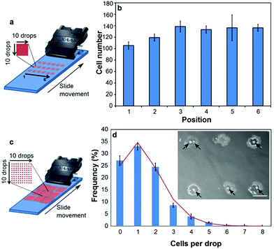 | ||
| Fig. 2 Printing cells from one inkjet print head. (a) Printed cell number across print head width was analyzed by counting cells printed in squares of 10 × 10 droplets (utilizing 10 nozzles each). Each sample contained 18 replicate squares as illustrated, printed in a single pass. (b) Cell number in the six squares positioned across the print head width, averaged for the three vertical replicates in three samples printed sequentially. Error bars represent one standard error of the mean (n = 3). One-way ANOVA indicated no statistically significant difference between the number of printed cells in each of the six positions. (c) Cells-per-drop distribution was analyzed by counting cells in individual drops printed in 10 × 10 arrays. Each sample contained 9 replicate arrays as illustrated, printed in a single pass. (d) Frequency distribution (bars) of the number of cells within individual printed droplets. Values were obtained by averaging the distributions in 3 arrays across the print head for two samples printed sequentially. Error bars represent one standard error of the mean (n = 3). The line graph represents a Poisson distribution, calculated using the total average of cells per drop in the analysed arrays. Inset: single printed droplets on glass containing C2C12 cells (black arrows). Scale bar 200 μm. | ||
Exposure to the bio-inks (with and without surfactants) did not have an apparent cytotoxic effect on either the C2C12 or PC12 cells (Fig. 3a). In fact, the viability of the bio-ink exposed PC12 cells was significantly higher than the control cells exposed to DMEM alone. This is likely due to the maintenance of a single cell suspension in the bio-inks, as opposed to cells in DMEM, which aggregated and settled and thus had to be re-suspended intermittently. Inkjet printed PC12 cells, and both inkjet and microvalve printed C2C12 cells, retained >95% viability (Fig. 3a) and were shown to proliferate over 48 h at a rate comparable to non-printed controls (Fig. 3b).
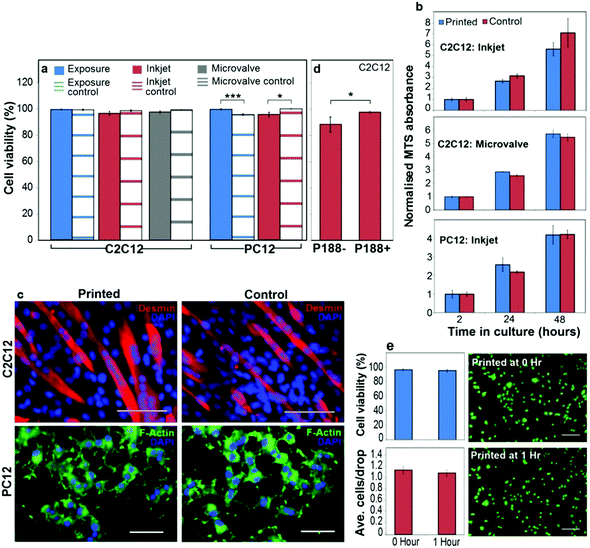 | ||
| Fig. 3 Printed cell viability, proliferation and differentiation. (a) Viability (assessed by live/dead staining after 2 h in culture) of C2C12 and PC12 cells from typical experiments where cells were either suspended in the bio-ink for 2 h and pipetted into culture wells (‘exposure’ conditions), or suspended in the bio-ink and printed into cell culture media by inkjet or microvalve printing. The control cells were suspended in DMEM for 2 h and pipetted into the culture wells. (b) MTS assay indicating proliferation of printed C2C12 (microvalve and inkjet printed) and PC12 (inkjet printed) cells in comparison to non-printed controls over 48 h in culture. MTS absorbance was normalized to the 2 h time point to account for the differences in initial cell numbers. (c) Differentiated C2C12 and PC12 cells on tissue culture polystyrene, comparing inkjet printed and control cells. Cells were stained for desmin (C2C12) or F-actin (PC12), as described in the ESI† (scale bars 100 μm for C2C12, or 50 μm for PC12). (d) Viability (after 2 h in culture) of C2C12 cells printed from bio-ink containing 0.1% v/v P188 (P188+), or with this surfactant omitted (P188−). (e) Comparison of C2C12 cells inkjet printed immediately and 1 h after loading the cells into inkjet print head. Top left – printed cell viability at both time points assessed by live/dead staining after 2 h in culture. Bottom left – average number of cells/drop at both time points. Right – Representative live/dead images of cells at both time points (scale bars 200 μm). (a, b, d, e) Error bars represent one standard error of the mean (n = 3), and the statistical significance was assessed by an unpaired Student's t-test and reported with either 99.9% (***) or 95% (*) confidence. | ||
A comparison of immunostained cells indicated that inkjet printed C2C12 and PC12 cells retained the ability to differentiate (Fig. 3c). Furthermore, omission of P188 from the surfactant-containing bio-ink decreased the viability of inkjet printed C2C12 cells (Fig. 3d), indicating a direct protective effect of P188 during the inkjet printing process. To demonstrate the utility of the surfactant-containing bio-ink to prevent cell settling during inkjet printing, we compared C2C12 cells printed immediately and then 1 h after loading into the print head. After a 1 h pause in printing, cell viability and density (average cells/drop) was no different to the initial values (Fig. 3e). Representative images of live/dead stained cells printed at these different time points (Fig. 3e) show cells with similar density, morphology and viability. Taken together, these results establish the bio-inks as providing a unique combination of printability and cell-suspending capability, whilst retaining the viability and function of printed cells.
Printing multiple cell types from different print heads is a highly attractive feature of inkjet printing as a biofabrication tool, allowing the fabrication of more complex multi-cellular constructs. Fig. 4a and b show two cell types (C2C12 and PC12) printed simultaneously from two different inkjet print heads in defined two-dimensional patterns onto collagen hydrogel substrates. Deposition of cells onto thin layers of collagen hydrogels ensured that the cells remained hydrated and viable for long enough to develop adhesions to the collagen, so that further addition of media did not disrupt the printed pattern. The cells were cultured under differentiation conditions and subsequently fixed and immunostained to assess the retention of printed patterns and the establishment of post-printing cell–cell and cell–substrate interactions. The bio-ink did not impede cellular interactions with the collagen substrate and both neural (PC12) and skeletal muscle (C2C12) cells were unimpeded in their ability to express the respective neural (β-III tubulin) and skeletal muscle (desmin) markers and to differentiate normally, as evidenced by the extension of dense neural networks from PC12 cells into surrounding areas populated by skeletal muscle cells (Fig. 4c and d).
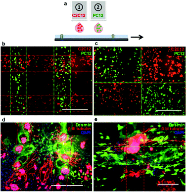 | ||
| Fig. 4 Patterning of two cell types printed simultaneously from two separate inkjet print heads onto collagen substrates. (a) Schematic representation of multiple head printing. (b, c) C2C12 (red) and PC12 (green) cells pre-stained with CellTracker™ dyes and printed in various patterns. Images were taken 1 h after printing, following the addition of the culture medium. (d, e) Printed patterns of C2C12 and PC12 cells after 8 days under differentiation conditions. Cells were immunostained for desmin (C2C12, green) and β-III tubulin (PC12, red). The dotted lines represent the outline of the printing pattern. Scale bars represent 500 μm (B–D) and 200 μm (E). | ||
Conclusions
The results reported in this work demonstrate key advances towards addressing the major challenges in the continuing evolution of drop-on-demand cell printing towards becoming a clinically relevant biofabrication tool. Primarily, our bio-inks display optimal fluid properties whilst addressing the multiple complications that arise from cell settling and aggregation. As we have demonstrated, this means that cell-containing structures can be printed simultaneously from separate print heads, over extended time periods while maintaining printed cell density and viability. This capability is fundamental to the fabrication of multi-cellular and/or larger structures.In this work even the printing of relatively simple dual-cell-type patterns in two dimensions was a time consuming task, and would not have been possible had the issues of cell settling and aggregation not been addressed. That printing was reproducible across the width of these print heads is further evidence of the utility of the bio-inks. It will allow more facile cell deposition, and enhance the accessibility of the technique by enabling the use of standard commercially available print heads. This work shows that smarter designs of bio-ink formulations can lead to important advances in cell printing approaches.
Acknowledgements
This work was supported by University of Wollongong (C. J. F.), and Centre of Excellence, Laureate (G. G. W.) and Future Fellowship (M. i.h.P.) funding from the Australian Research Council (ARC). We thank P. Jackson and R. C. Clark (both from C. P. Kelco) for provision of gellan gum and advice on rheology.Notes and references
- P. Calvert, Printing cells, Science, 2007, 318, 208–209 CrossRef CAS.
- B. Guillotin and F. Guillemot, Cell patterning technologies for organotypic tissue fabrication, Trends Biotechnol., 2011, 29, 183–190 CrossRef CAS.
- D. Castel, A. Pitaval, M. A. Debily and X. Gidrol, Cell microarrays in drug discovery, Drug Discovery Today, 2006, 11, 616–622 CrossRef CAS.
- M. L. Yarmush and K. R. King, Living-cell microarrays, Annu. Rev. Biomed. Eng., 2009, 11, 235–257 CrossRef CAS.
- V. Mironov, et al. Organ printing: tissue spheroids as building blocks, Biomaterials, 2009, 30, 2164–2174 CrossRef CAS.
- R. Gaetani, et al. Cardiac tissue engineering using tissue printing technology and human cardiac progenitor cells, Biomaterials, 2012, 33, 1782–1790 CrossRef CAS.
- N. R. Schiele, et al. Laser-based direct-write techniques for cell printing, Biofabrication, 2010, 2, 032001 CrossRef.
- M. Gruene, et al. Laser printing of stem cells for biofabrication of scaffold-free autologous grafts, Tissue Eng., Part C, 2011, 17, 79–87 CrossRef.
- S. J. Moon, et al. Layer by layer three-dimensional tissue epitaxy by cell-laden hydrogel droplets, Tissue Eng., Part C, 2010, 16, 157–166 CrossRef CAS.
- F. Xu, et al. A droplet-based building block approach for bladder smooth muscle cell (SMC) proliferation, Biofabrication, 2010, 2, 014105 CrossRef CAS.
- W. C. Wilson and T. Boland, Cell and organ printing 1: protein and cell printers, Anat. Rec., 2003, 272, 491–496 CrossRef.
- T. Xu, J. Jin, C. Gregory, J. J. J. J. Hickman and T. Boland, Inkjet printing of viable mammalian cells, Biomaterials, 2005, 26, 93–99 CrossRef CAS.
- R. E. Saunders, J. E. Gough and B. Derby, Delivery of human fibroblast cells by piezoelectric drop-on-demand inkjet printing, Biomaterials, 2008, 29, 193–203 CrossRef CAS.
- T. C. Burg, C. a P. Cass, R. Groff, M. E. Pepper and K. J. L. Burg, Building off-the-shelf tissue-engineered composites, Philos. Trans. R. Soc. London, Ser. A, 2010, 368, 1839–1862 CrossRef CAS.
- M. E. Pepper, V. Seshadri, T. C. Burg, K. J. L. Burg and R. E. Groff, Characterizing the effects of cell settling on bioprinter output, Biofabrication, 2012, 4, 011001 CrossRef.
- S. Parsa, M. Gupta, F. Loizeau and K. C. Cheung, Effects of surfactant and gentle agitation on inkjet dispensing of living cells, Biofabrication, 2010, 2, 025003 CrossRef.
- W. Lee, et al. Multi-layered culture of human skin fibroblasts and keratinocytes through three-dimensional freeform fabrication, Biomaterials, 2009, 30, 1587–1595 CrossRef CAS.
- C. A. Parzel, M. E. Pepper, T. C. Burg, R. E. Groff and K. J. L. Burg, EDTA enhances high-throughput two-dimensional bioprinting by inhibiting salt scaling and cell aggregation at the nozzle surface, J. Tissue Eng. Regener. Med., 2009, 3, 260–268 CrossRef CAS.
- B. Derby, Inkjet printing of functional and structural materials: fluid property requirements, feature stability, and resolution, Annu. Rev. Mater. Res., 2010, 40, 395–414 CrossRef CAS.
- K. Arai, et al. Three-dimensional inkjet biofabrication based on designed images, Biofabrication, 2011, 3, 034113 CrossRef.
- A. R. Liberski, J. T. Delaney and U. S. Schubert, “One cell-one well”: a new approach to inkjet printing single cell microarrays, ACS Comb. Sci., 2011, 13, 190–195 CrossRef CAS.
- T. Xu, et al. Viability and electrophysiology of neural cell structures generated by the inkjet printing method, Biomaterials, 2006, 27, 3580–3588 CAS.
- X. Cui and T. Boland, Human microvasculature fabrication using thermal inkjet printing technology, Biomaterials, 2009, 30, 6221–6227 CrossRef CAS.
- X. Cui, K. Breitenkamp, M. G. Finn, M. Lotz and D. D. D'Lima, Direct human cartilage repair using three-dimensional bioprinting technology, Tissue Eng., Part A, 2012, 18, 1304–1312 CrossRef CAS.
- Y. Nishiyama, et al. Development of a three-dimensional bioprinter: construction of cell supporting structures using hydrogel and state-of-the-art inkjet technology, J. Biomech. Eng., 2009, 131, 035001 CrossRef.
- T. Xu, et al. Characterization of cell constructs generated with inkjet printing technology using in vivo magnetic resonance imaging, J. Manuf. Sci. Eng., 2008, 130, 021013 CrossRef.
- A. M. Fialho, et al. Occurrence, production, and applications of gellan: current state and perspectives, Appl. Microbiol. Biotechnol., 2008, 79, 889–900 CrossRef CAS.
- A. M. Smith, R. M. Shelton, Y. Perrie and J. J. Harris, An initial evaluation of gellan gum as a material for tissue engineering applications, J. Biomater. Appl., 2007, 22, 241–254 CrossRef CAS.
- C. J. Ferris and M. in het Panhuis, Conducting bio-materials based on gellan gum hydrogels, Soft Matter, 2009, 5, 3430–3435 RSC.
- J. T. Oliveira, et al. Gellan gum: a new biomaterial for cartilage tissue engineering applications, J. Biomed. Mater. Res., Part A, 2010, 93A, 852–863 CAS.
- K. Y. Lee and D. J. Mooney, Alginate: properties and biomedical applications, Prog. Polym. Sci., 2012, 37, 106–126 CrossRef CAS.
- E. R. Morris, K. Nishinari and M. Rinaudo, Gelation of gellan gum – a review, Food Hydrocolloids, 2012, 28, 373–411 CrossRef CAS.
- M. Caggioni, P. T. Spicer, D. L. Blair, S. E. Lindberg and D. A. Weitz, Rheology and microrheology of a microstructured fluid: the gellan gum case, J. Rheol., 2007, 51, 851 CrossRef CAS.
- G. S. Sworn, G. R. Sanderson and W. Gibson, Gellan gum fluid gels, Food Hydrocolloids, 1995, 9, 265–271 CrossRef CAS.
- E. T. Papoutsakis, Media additives for protecting freely suspended animal cells against agitation and aeration damage, Trends Biotechnol., 1991, 9, 316–324 CrossRef CAS.
- M. Krafft, Fluorocarbons and fluorinated amphiphiles in drug delivery and biomedical research, Adv. Drug Delivery Rev., 2001, 47, 209–228 CrossRef CAS.
- X. Li, et al. Hydrophobic tail length, degree of fluorination and headgroup stereochemistry are determinants of the biocompatibility of (fluorinated) carbohydrate surfactants, Colloids Surf., B, 2009, 73, 65–74 CrossRef CAS.
- J. A. Barron, D. B. Krizman and B. R. Ringeisen, Laser printing of single cells: statistical analysis, cell viability, and stress, Ann. Biomed. Eng., 2005, 33, 121–130 CrossRef.
Footnote |
| † Electronic supplementary information (ESI) available: Diagram of inkjet printing, PDMS well, rheology and surface tension of bio-ink, and methods for cell viability, cell proliferation and differentiation and immunostaining. See DOI: 10.1039/c2bm00114d |
| This journal is © The Royal Society of Chemistry 2013 |