
 Open Access Article
 This Open Access Article is licensed under a Creative Commons Attribution-Non Commercial 3.0 Unported Licence
Rechargeable iron-ion (Fe-ion) batteries: recent progress, challenges, and perspectives
Jitendra Kumar
Yadav
 ,
Bharti
Rani
,
Priyanka
Saini
and
Ambesh
Dixit
*
,
Bharti
Rani
,
Priyanka
Saini
and
Ambesh
Dixit
*
Advanced Material and Devices Laboratory (A-MAD), Department of Physics, Indian Institute of Technology, Jodhpur, Rajasthan 342030, India. E-mail: ambesh@iitj.ac.in
First published on 2nd April 2024
Abstract
With the ever-increasing demand for efficient and sustainable energy solutions, rechargeable Fe-ion batteries have emerged as a viable alternative to conventional rechargeable batteries. Rechargeable Fe-ion batteries are considered one of the most promising energy storage devices due to their low cost, abundance, eco-friendliness, and enhanced safety. This review article provides an in-depth overview of the essential components, such as electrodes and electrolytes, for all Fe-ion-based rechargeable batteries and emphasizes their distinctive features and potential advantages. Furthermore, it covers the current state of rechargeable Fe-ion batteries, highlighting recent advancements in electrode materials. It provides the details of recent findings on the electrochemical characteristics of rechargeable Fe-ion batteries, including their Fe-anode coulombic efficiency, capacity, cycling stability, and safety aspects for both aqueous and non-aqueous rechargeable Fe-ion batteries. It addresses the significance of various material innovations and engineering strategies to develop efficient electrode and electrolyte materials. It also highlights the current challenges for the cathode, anode, and electrolyte of rechargeable Fe-ion batteries, followed by their future perspectives. In conclusion, this review provides valuable insights into rechargeable Fe-ion batteries in a broader context for researchers to develop Fe-ion batteries as potential candidates for future energy storage technologies.
1. Introduction
The growing utilization of renewable energy sources for electrical power generation has sparked significant interest in ensuring the dependability and efficiency of the grid infrastructure while also leading to a decrease in the accessibility of fossil fuels.1,2 To address these ongoing energy problems, it is imperative to create a cost-effective and eco-friendly energy storage system that can effectively support/mitigate intermittent renewable energy sources like solar and wind power.3–6 Electrical energy storage systems have the potential to improve the stability and efficiency of the electrical grid, optimize the use of renewable resources, and promote the adaptability of integrating sustainable energy into the power system.7,8 Large-scale energy storage applications provide numerous technological and technical obstacles, such as safety, consistency, cost-effectiveness, and commercial acknowledgment.9–15 In the energy storage sector, batteries are taking all over the market. In general, lithium seems to be a preferable choice among rechargeable batteries.16–20 The name battery itself gives rise to the thought in one's conscious mind that it would be the lithium-ion battery. The increasing demand for lithium and its scarcity, toxicity, and flammability cause various issues towards sustainability21,22 However, the chemistry of lithium is mature. The other options, like sodium and potassium-ion batteries, also exhibit similar chemistry but have several challenges.23–26 That's why researchers are looking for such viable options that can be cost-effective and toxin-free to maintain the promise of sustainability.27–29Numerous multivalent metals, like aluminum, zinc, magnesium, iron, etc., are being explored in the form of metal-ion, metal–air, and redox-flow batteries.30–37 Among them, zinc metal has caught most of the attraction as it exhibits a low redox potential in both acidic and alkaline media and contains high gravimetrical capacity (theoretical ∼820 mA h g−1).38–41 Aluminum is the most abundant metal with a high theoretical gravimetric and volumetric capacity, i.e., 2980 mA h g−1 and 8040 mA h cm−3, respectively.42–46 Despite these attractive numbers, aluminum and even magnesium suffer from severe hydrogen evolution reactions, which limits their potential applications, and are not being used practically in a broader way.47–49 Coming on to iron, it features as the fourth most abundant element and the second most abundant metal in the earth's crust with ease of processing and cost-effectiveness and is frequently used in nano-engineering as a dopant.50 Iron's gravimetric and volumetric specific capacities are also appealing in numbers, up to ~ 960 mA h g−1 and 7550 mA h cm−3, respectively. Thus, the Fe-ion battery attracts attention due to its stable high redox potential against standard hydrogen electrodes (SHE) in acidic electrolytes. A detailed comparison of capacity, abundance, price, cation radius, and SHE potential is shown in Fig. 1(a) for various mono-valent and multivalent metal anodes. Iron metal-based batteries have taken a significant turn in the last 25 years. Researchers started exploring iron as the metal anode to overcome the challenges of conventional rechargeable batteries. The ambient processable nature of iron compelled the focus on all iron-based batteries, which can be non-toxic, non-flammable, and cost-effective alternatives for energy storage devices. Various unique characteristics of Fe-ion batteries are also shown in Fig. 1(b), which make them a viable solution for alternative energy storage technologies.
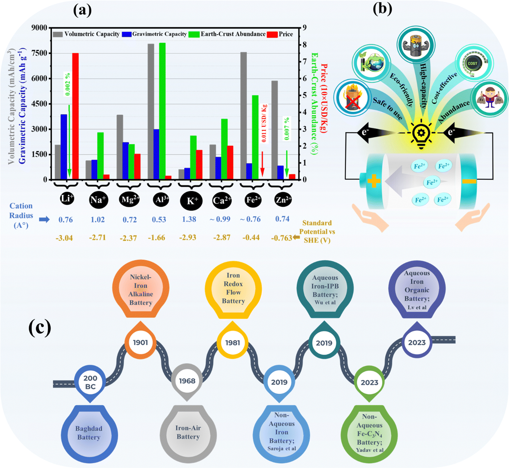 | ||
| Fig. 1 (a) Various mono and multivalent metal-ion battery parameters in terms of volumetric capacity, gravimetric capacity, earth-crust abundance percentage, price, cation radius, and standard potential vs. SHE. (b) Schematic representation of the characteristics of Fe-ion batteries. (c) Timeline of the progress in iron metal-based rechargeable batteries. | ||
There are some shreds of evidence that the first iron-based battery was developed by artisans of Baghdad, way back in 200 BC.51 Historically, iron-based batteries came into the picture with the invention of nickel–iron (Ni–Fe) alkaline batteries in 1901 by Edison and Junger. Around 1910 or so, Ni–Fe batteries containing iron-based anodes and nickel-based cathodes in alkaline electrolytes were commercialized for various applications. Later on, Ni–Fe batteries were developed mainly in the last 30 years to improve the overall efficiency of the battery.52–65 Next, iron–air and iron-redox flow batteries were also developed in 1961 and 1981, respectively, and popularized with time. After that, various findings were reported on developing the electrodes and electrolytes for the iron–air and iron-redox flow batteries.33,66–82 From 2019 onwards, research has mainly focused on developing rechargeable Fe-ion batteries beyond the alkaline electrolyte, which is the primary focus of this review article. A brief timeline of the development of various iron metal-based batteries, including the recently developed high-performance aqueous and non-aqueous rechargeable Fe-ion batteries, is summarized in Fig. 1(c).
Despite their long lifespan and durability, nickel–iron batteries suffer from several limitations. Their lower storage capacity compared to modern counterparts like lithium-ion batteries makes them bulky and heavy. Slow charging and discharging processes also hinder their wider use. Hydrogen gas evolution during charging requires careful maintenance, adding complexity to the entire system.58 While promising for long-term energy storage, iron–air batteries face numerous hurdles. Fe–air batteries exhibit a very low energy density, ∼80 to 110 W h kg−1, compared with conventional energy storage technology. They suffer from low efficiency, with losses due to hydrogen production and sluggish oxygen reactions. The iron anode corrodes easily, forming harmful dendrites. The air cathode needs better catalysts and improved stability to handle varying humidity and CO2. Their bulky size and slow recharge times also limit their applications.80 Similarly, iron redox flow batteries also face many challenges.77 The electrochemical activity of these iron metal-based batteries is limited by passivation, parasitical hydrogen evolution reaction, and low electroplating efficiency in alkaline electrolytes, which hinders their lasting practical use. In this scenario, the current focus is on exploring the potential of rechargeable Fe-ion batteries based on acidic aqueous and non-aqueous electrolytes.83,84
In brief, this review article summarizes the recent advancements in developing anode, cathode, and electrolyte materials for rechargeable Fe-ion batteries, including the essential components, reaction mechanism, and selection criteria of the different materials. It mainly focuses on critical approaches such as electrolyte alteration, and nanoengineering of different electrode components to enhance the electrochemical performance, followed by the challenges and perspectives. This study aims to establish a fundamental understanding of rechargeable Fe-ion batteries as a potential alternative for clean and green energy storage systems.
2. Operational mechanism and design criteria of electrodes and electrolytes
Rechargeable Fe-ion batteries consist of three essential components, anode, cathode, and electrolyte, that enable electrochemical energy storage. All these components, including the charge–discharge mechanism of the Fe-ion battery, are explained schematically in Fig. 2(a). In the charging–discharging process, Fe2+ ions shuttle between the anode and cathode through the electrolyte, while electrons flow between the anode and cathode through the external circuit. In the charging process, Fe2+ ions and e− move from the cathode to the anode through the electrolyte and outer circuit, respectively. In discharging process, Fe2+ ions and e− move from the anode to the cathode, i.e. vice-versa of charging mechanism. A detailed charging process is indicated using green color arrows and discharging process using red color arrows in Fig. 2(a).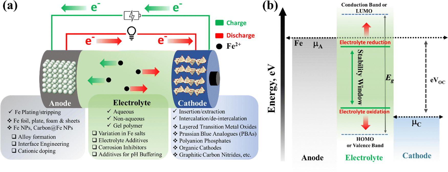 | ||
| Fig. 2 (a) A detailed schematic of materials required for the anode, cathode, and electrolyte, including the charge–discharge mechanism. (b) Energy diagram showing different energy states of the anode, cathode, and electrolyte together with the stability window for rechargeable Fe-ion batteries. | ||
The anode typically utilizes iron-based materials, such as Fe plates, sheets, and foil, including various Fe and carbon-coated Fe nanostructures. It (i.e., anode) can be modified via interface engineering and different surface modification techniques. Where Fe-ions follow the plating/stripping process during the cycling, the reaction can be expressed as Fe(s) ↔ Fe2+(aq) + 2e− (E° = −0.44 V vs. SHE). During discharging (stripping), Fe-ions are released from the Fe-based anode to the electrolyte. Further, Fe2+ ions reversely return to the anode from the electrolyte during the charging (plating) process. The cathode should be capable of hosting Fe-ion intercalation reactions or insertion/extraction mechanisms during cycling. It contains mostly layered metal oxides, Prussian blue analogues, polyanion phosphates, various organic-based cathode materials, etc. During discharge (intercalation), Fe2+ ions are inserted into the host cathode from the electrolytes, those Fe2+ are released by the anode. During charge (deintercalation), Fe2+ ions are reversely de-inserted or dissolved from the host cathode to the electrolyte, which can participate in plating at the anode. The electrolyte contains various iron-based salts, including sulfate, chloride, perchlorate, etc., in a suitable solvent. The electrolyte facilitates ion movement between electrodes during charging and discharging based on the aqueous, non-aqueous and gel–polymer electrolyte. Further, various additives and inhibitors can also be used to improve the efficiency of the anode and reduce the hydrogen evolution reaction during the cycling process.
The energy band diagram for the Fe-ion battery is shown in Fig. 2(b), explaining the relative electronic states of anode, electrolyte, and cathode materials. This energy diagram may assist in understanding the design criteria for selecting the rechargeable Fe-ion batteries' anode, cathode, and electrolyte materials. The electrolyte's LUMO level should consistently be below the chemical potential of the anode (μA) and the HOMO level should consistently be above the chemical potential of the cathode (μC) for electrolyte stability. Otherwise, the electrolyte may break down, resulting in battery failure. It also follows eVoc = μA − μC, which suggests that the difference between the chemical potentials of the anode and cathode should be higher for electrolyte stability and a large operating voltage.85–88 The higher operating voltage will result in higher operating power for the device. Thus, a material with a relatively large bandgap and relatively large lattice spacing will be a suitable cathode candidate for these batteries. Large bandgap materials are usually insulating; thus, material innovation is essential for higher electronic conductivity to realize efficient carrier transport at the cathode end in iron-ion batteries. Thus, anodes, electrolytes, and cathodes with suitable electronic properties are essential for efficient iron-ion batteries.
A detailed description of electrolyte, cathode, and anode development is provided in the following sections/sub-sections. A separator prevents electrical contact, i.e., short-circuiting, between the anode and cathode. This separator is usually made of glass fiber or filter paper. The current collector is also a crucial component that facilitates the flow of electrons between the electrodes and the external circuit. For better suitability, we must choose the current collectors according to the electrodes and chemical characteristics of electrolyte. Generally, Fe sheets/plates work as the current collector at the anode side, and in the case of Fe NPs, copper is used as the current collector. At the cathode side, mostly carbon fiber paper, graphite paper, stainless steel foil, stainless steel mesh, and titanium mesh are explored as the current collectors.83,84
3. Electrolyte development
The electrolyte is a critical component in rechargeable batteries, playing a fundamental role in facilitating the movement of ions between the positive (cathode) and negative (anode) electrodes during charge and discharge cycles. The choice of electrolyte significantly influences the performance, safety, and overall efficiency of the battery.89,90 In the context of Fe-ion batteries, which utilize Fe-ions as charge carriers, the electrolyte must meet specific requirements to ensure optimal battery performance, as discussed in the previous section. The primary function of the electrolyte is to enable the reversible redox reactions involving Fe-ions at the cathode and anode. Fe-ions migrate from the anode to the cathode during discharge, releasing electrons and generating electrical energy. Fe-ions return to the anode during recharge, absorbing electrons and storing electrical energy. The critical components for developing the electrolyte include high ionic conductivity, redox stability in multiple galvanostatic charge/discharge (GCD) cycles, compatibility with both electrodes, and high solubility of the Fe-ion salts, which are necessary to consider. Both aqueous and non-aqueous electrolytes have been developed by considering these constraints for rechargeable Fe-ion batteries.3.1 Aqueous electrolyte
Aqueous electrolytes are well known due to their high ionic conductivity compared to non-aqueous electrolytes, cost-efficient and environment-friendly nature, and high ion solubility.91 Due to its unique characteristics, an aqueous electrolyte is mainly explored for rechargeable Fe-ion batteries. Various salts, including FeSO4, FeClO4, Fe(OTF)2, FeCl2, etc., are used in different molar ratios. Xiulei Ji et al. explored different molarity FeSO4-based aqueous electrolytes for the aqueous rechargeable Fe-ion batteries under a N2-filled glove box before use in the coin cell. They purged the electrolyte with N2 to remove the dissolved O2 from the electrolyte.92–94 FeSO4 salt based electrolyte was explored in different molarities ranging from 0.5 molar to 1 molar.95–98 As reported in various studies, iron(II) trifluoromethanesulfonate (Fe(CF3SO3)2, Fe(OTF)2) is considered the best Fe-ion salt among the others for the aqueous rechargeable Fe-ion batteries due to high electrochemical performance. The charge–discharge schematic for an aqueous electrolyte is shown in Fig. 3(a) based on the Fe(OTF)2 salt and PANI cathode. Iron(III) trifluoromethanesulfonate (Fe(CF3SO3)3) also worked as the aqueous electrolyte with better cycling performance than the FeSO4 electrolyte in organic (PANI) based cathode materials, as shown in Fig. 3(b), because when the electrolyte came across Fe, then Fe3+ reduced to Fe2+, as shown in Fig. 3(c), via optical photographs. Further, the Fe plating/stripping process was also investigated in all electrolyte systems for various current densities, ranging from 0.125 to 1 mA cm−2, as shown in Fig. 3(d)–(f). The reversible electroplating and stripping processes are higher for three molar Fe(OTF)2 than for the other electrolytes.99 A comparison between FeSO4 and Fe(OTF)2 was also performed based on the VOPO4-based cathode, where the Fe(OTF)2 electrolyte showed high cyclic performance along with high cycling stability, as shown in Fig. 3(g).100 Further, the cyclic stability of Fe(OTF)2 in various molar ratios was compared with the FeSO4 and the Fe(ClO)4 electrolyte together with the VO2-based cathode materials. The best cycling stability was shown by the 3 molar Fe(OTF)2 electrolyte, as shown in Fig. 3(h). The operating charging–discharging voltage window is also important due to the polarization of the iron electrode, which is theoretically limited to 0–1.21 V.101 All the explored aqueous electrolytes for Fe-ion batteries are also summarized in Table 2 with the respective electrodes and electrochemical performance.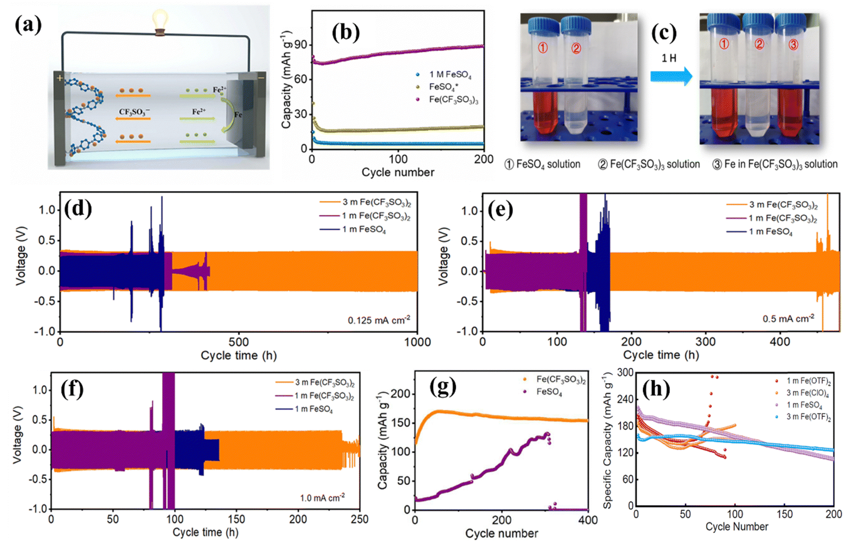 | ||
| Fig. 3 (a) Schematic of the aqueous Fe-ion batteries based on the Fe(OTF)2 electrolyte. (b) GCD performance based on 1 M FeSO4, modified FeSO4, and Fe(OTF)3 electrolytes at 0.2 A g−1. (c) Optical photos of the reduced electrolyte. (d)–(f) Voltage vs. time profile at current densities 0.125, 0.5, and 1.0 mA cm−2, respectively.99 (g) GCD performance for different aqueous electrolytes at 0.2 A g−1 together with the VOPO4 cathode.100 (h) Specific capacity vs. cycle number for different aqueous electrolytes along the VO2 cathode.101 | ||
3.2 Non-aqueous electrolyte
Non-aqueous electrolytes confer several advantages for rechargeable Fe-ion batteries, including the ability to operate within higher voltage windows than the aqueous-based electrolyte, which enhances energy density. These non-aqueous electrolytes are less susceptible to corrosion and leakage, improving safety and cycle life. However, low ionic conductivity of these electrolytes reduces the power density of the battery.102 Non-aqueous electrolytes are categorized as discussed below.| S. no. | Anode | Cathode | Electrolyte | Specific capacity (mA h g−1) | Current rate (mA g−1) | Performance (capacity retention %, in no. of cycles at current density, mA g−1) | Ref. |
|---|---|---|---|---|---|---|---|
| 1 | Mild steel | Bulk V2O5 | 1 molar FeClO4·xH2O in TEGDME | 207 | 30 | ∼54% in 50 cycles at 33 | 103 |
| 2 | Graphite | C/Fe, C/Fe2O3 | BmimFeCl4 ionic liquid | 20–100 | — | — | 106 |
| 3 | Mild steel | V2O5 | 1 molar FeClO4·xH2O in TEGDME (ambient synthesis) | 120 | 33 | ∼50% in 30 cycles | 104 |
| 4 | Mild steel | g-C3N4 | 1 molar FeClO4·xH2O in TEGDME (ambient synthesis) | 130 | 40 | 60% in 240 cycles at 3C rate | 105 |
3.3 Gel-based electrolyte
Gel-based electrolytes are gaining popularity in multivalent rechargeable batteries due to their unique blend of properties that address some of the key challenges conventional that liquid and solid electrolytes face. They offer a compelling combination of safety, performance, and flexibility, making them a promising technology for the next generation of multivalent metal-ion rechargeable batteries.107 Recently, Lv et al. reported a gel-based electrolyte containing a 3D framework structure based on the PAM-based electrolyte. The film was soaked in aqueous electrolyte of 1 M Fe(TOF)2 for 12 h in an N2-filled glove box before being used for electrochemical evaluation. The coin cell-based Fe-ion battery on this PAM gel film showed ultra-high cyclic stability for more than 39![[thin space (1/6-em)]](https://www.rsc.org/images/entities/char_2009.gif) 000 cycles at a high current rate of 25 A g−1.108
000 cycles at a high current rate of 25 A g−1.108
3.4 Electrolyte additives
Electrolyte additives are important in enhancing the coulombic efficiency (CE), which ultimately suppresses the HER and oxidation of the iron-based anode in the acidic electrolyte.109 Electrolyte additives have already been widely explored for alkaline-based aqueous Fe–air and Ni–Fe batteries to enhance the performance of the pristine Fe anode.81,110 Chai et al. reported an NH4Cl regulator for cost-effective rechargeable aqueous Fe-ion batteries. Adding NH4Cl to the electrolyte enhances the performance of the anode by inhibiting the passivation reaction, together with a higher CE than pure FeSO4-based electrolytes. Fig. 4(a) shows the working mechanism of the iron metal anode in the presence of the electrolyte with additives and without additives. Here, NH4Cl works as the buffering agent and adjusts the pH value to the neutral level, which decreases the concentration of H+ ions. It prevents the formation of a thick film at the surface of Fe, thus increasing the diffusivity of Fe-ions. The symmetric cell based on Fe with the modified electrolyte was characterized at various current densities, as shown in Fig. 4(b). The cell shows high stability for the time versus voltage profile without showing voltage fluctuation from 1 mA cm−2 to 10 mA cm−2 for more than 100 h. Fig. 4(c) shows the CE percentage against cycle number for electrolytes based on FeSO4 and FeSO4/NH4Cl, where FeSO4/NH4Cl shows higher stability with CE percentage ∼96% for more than 1000 cycles.111,112 Recently, Liu et al. reported the high efficiency of electroplating and stripping for Fe metal batteries by adding Mg and Ca ions to the electrolyte containing a chloride salt. Adding 4.5 M MgCl2 and 4.5 M CaCl2 in FeCl2 enhances the CE, conductivity, and the deposition/stripping process by suppressing the HER, as shown schematically in Fig. 4(d). This system offers high stability for Mg and Ca-ion based electrolytes for Fe/Fe symmetric cells, where the pure Fe-based electrolyte battery fails in 88 h at a current density of 1 mA cm−2; at the same time, the modified electrolyte system works for more than 250 h, as shown in Fig. 4(e).113 Further, Wu et al. developed aqueous iron-iodine batteries based on adding ZnI2 in the aqueous electrolyte to regulate the Fe deposition behaviour via Zn doping. When a 1 M ZnI2 electrolyte was added into the 5 M FeCl2 electrolyte, Zn–I complexes formed, and [ZnI]+ adsorbed at the surface of Fe. The Zn-ions are allowed in the Fe lattice and enhanced the coulombic efficiency of Fe metal during reduction process in an aqueous electrolyte. The reversible process of Fe plating/stripping was carried out in Fe/Ti asymmetric cells using three different electrolytes, including FeCl2, FeCl2 + ZnCl2, and FeCl2 + ZnI. Fig. 4(f) shows the CE with cycle number at 0.5 mA cm−2, showing the unstable behaviour of FeCl2 and FeCl2 + ZnCl2, where the CE is highly stable for more than 1200 cycles for the FeCl2 + ZnI electrolyte. The study of voltage vs. time suggests a stable electroplating and stripping process for FeCl2/ZnI for more than 300 h at a high current rate of 10 mA cm−2, where the other two electrolytes stop working before 200 h cycling, as shown in Fig. 4(g). Further, a cell was cycled based on the FeCl2 + ZnI electrolyte, and was found to be stable for more than 2500 h at 1 mA cm−2, as shown in Fig. 4(h).114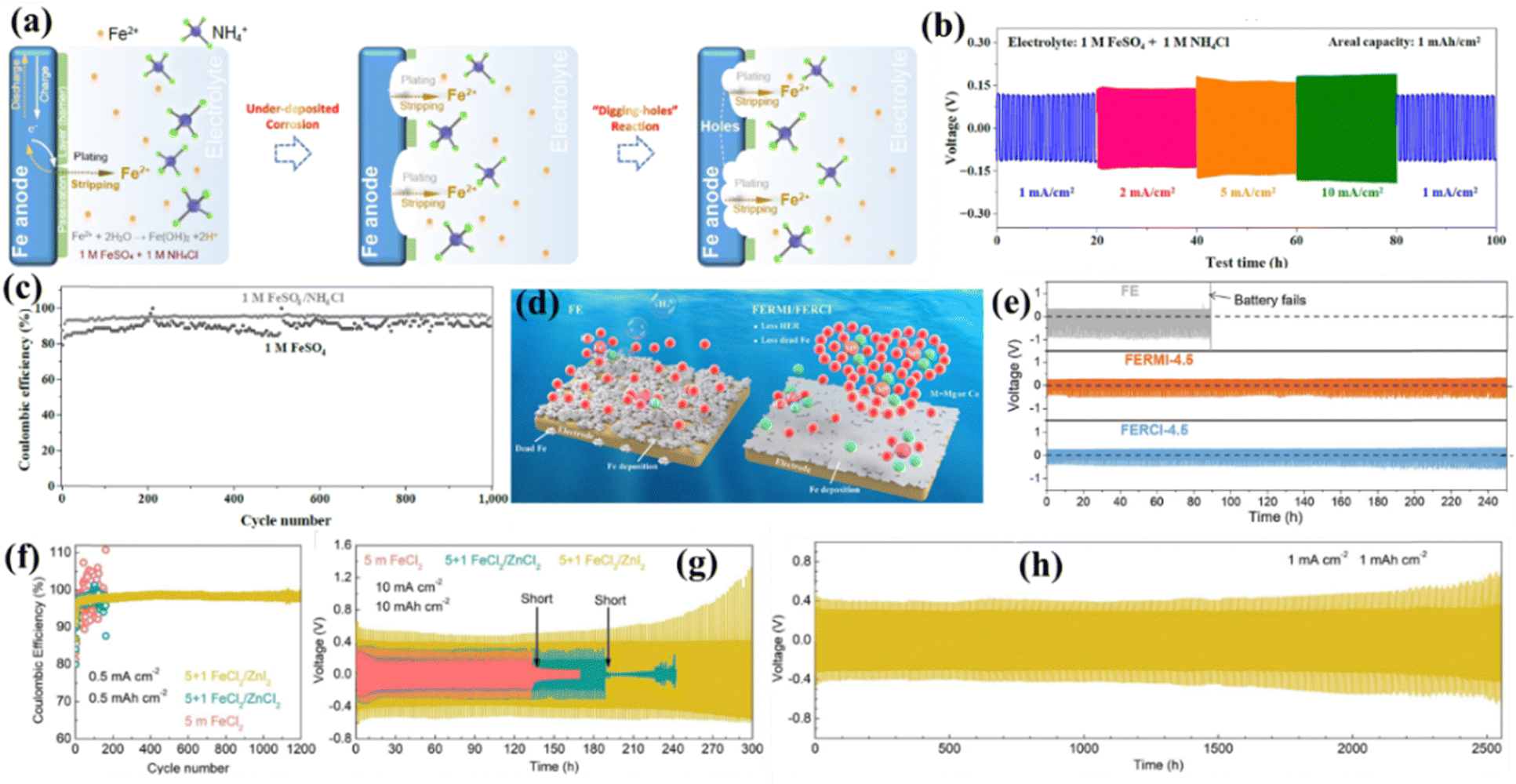 | ||
| Fig. 4 (a) Working mechanism of plating/stripping in the presence of NH4Cl additives. (b) Voltage vs. time profile at various current densities for NH4Cl additives. (c) CE with cycle number with and without additives.111 (d) Schematic of the effect of Mg and Ca-ions at the Fe surface. (e) Voltage vs. time for the pure Fe electrolyte and that modified by the Ca, Mg ion based salt.113 (f) CE with cycle number for different electrolyte systems at 0.5 mA cm−2. (g) Voltage vs. time at high current densities for different electrolytes. (h) Voltage vs. time at 1 mA cm−2 for the FeCl2/ZnI2 system.114 | ||
4. Cathode materials
Cathode materials for Fe-ion batteries are pivotal as these provide an Fe-ion storage framework/structure, that decides the overall discharging plateau and capacity along with the cyclic stability of the battery. Researchers have recently explored various cathode materials to enhance capacity and cyclic stability. Based on the compound and structure, these cathode materials can be categorized into vanadium-based oxides, vanadium phosphates, Prussian blue analogues (PBA), sulfur, and its composites, polyaniline (PANI), and carbon-based cathodes. All these compounds have different structures and properties, leading to varied electrochemical performance along with different Fe-ion storage mechanisms. All the explored cathode materials for the non-aqueous and aqueous Fe-ion batteries are also summarized in Tables 1 and 2, respectively, with their electrochemical performance parameters.| S. no. | Anode | Cathode | Electrolyte | Specific capacity (mA h g−1) | Current rate (mA g−1) | Performance (capacity retention %, in no. of cycles, at current density, with average CE %) | Ref. |
|---|---|---|---|---|---|---|---|
| 1 | Fe NPs | Prussian blue analogue | 0.5 M FeSO4 | 60 | 1C | 80%, 1000 cycles, 10C rate, CE ∼99.3% | 92 |
| 2 | Fe NPs | Sulfur/carbon | 0.5 M FeSO4 | ∼1050 | 50 | Stable cycling of 150 cycles | 94 |
| 3 | Fe treated with ascorbic acid | I2/N doped porous carbon | 1 M FeSO4 | 190 | 5000 | ∼100%, 550 cycles, 2 A g−1 | 97 |
| 4 | Fe NPs | VOPO4·2H2O | 1 M FeSO4 | 100 | 100 | 68%, 800 cycles, 1C rate | 93 |
| 5 | Fe metal | PANI | 5 M FeCl2 with 1 M ZnI2 | 2 mA h cm−2 | 8 mA cm−2 | 99.8%, 1200 cycles, 8 mA cm−2, CE ∼96.7%. | 114 |
| 6 | Fe foam | Carbon foam | 1 M FeSO4 + NH4Cl | — | — | CE of anode ∼96% at a higher current rate | 111 |
| 7 | Fe foil | Phenylamine (PA)-intercalated VOPO4 | 3 M Fe(CF3SO3)2 | 170 | 200 | 96.2%, 2200 cycles, 1 A g−1 | 100 |
| 8 | Fe foil | Mg-Substituted Prussian blue nanocubes | 0.5 M FeSO4 | 96 | 200 | 70.9%, 500 cycles, 1 A g−1 | 96 |
| 9 | Fe plate | Tunnel like VO2 | 3 M Fe(CF3SO3)2 | 198 | 200 | 78.9%, 200 cycles, 0.5 A g−1 | 101 |
| 10 | Fe foil | Cross-linked PANI | 1 M Fe(CF3SO3)2, 1 M Fe(CF3SO3)2 with polymer film | 110 | 25000 |
Cyclic stability of more than 39000 cycles |
108 |
| 11 | Fe plate | PANI | 3 M Fe(CF3SO3)2 | 105.8 | 50 | 5000 cycles without capacity fading at 0.2 A g−1 | 99 |
| 12 | MXene/Fe | PANI | 1 M FeSO4 | 46 | 200 | Stability more than 100 h at 0.5 mA cm−2 | 95 |
| 13 | Fe | I2/FeP-NPC@carbon shell | 1 M FeSO4 | 202 | 200 | 90%, 500 cycles | 98 |
| 14 | Mild steel | g-C3N4 | 1 M FeSO4 (ambient synthesis) | 135 | 1000 | 50%, 50 cycles | 115 |
| 15 | Fe foil | Defect-rich MoS2 | 3 M Fe(CF3SO3)2 | 123 | 100 | 88%, 600 cycles, 200 mA g−1 | 116 |
4.1 Vanadium-based oxides and phosphates
Vanadium-based compounds, including vanadium oxides and vanadium phosphates, are the most explored cathode materials for Fe-ion batteries because vanadium can exist in multiple oxidation states, such as V2+, V3+, V4+, and V5+. This property allows for various redox reactions to occur during the charging and discharging cycles, facilitating the storage of Fe-ions with high capacity and working potential.117 The A-MAD group and Saroja et al. explored a V2O5 efficient cathode material for the rechargeable Fe-ion batteries based on the 1 M iron perchlorate-based non-aqueous electrolyte assembled under ambient conditions. The charge–discharge mechanism of the non-aqueous Fe-ion batteries is shown in Fig. 5(a), V2O5, works as the intercalation and deintercalation-based cathode material due to its large layer spacing, which provides effective Fe2+ ion storage into the structure. Fig. 5(b) shows that CV plots at various scan rates to analyze the diffusive or capacitive process. Fig. 5(c) shows that the slope of the log(Imax) vs. log scan rate curve is equal to ∼0.54 using the power law, which shows that the process of Fe2+ storage in V2O5 is dominated by the diffusion process rather than the capacitive process. GCD cycling was investigated at various current rates, where the low current density of 33 mA g−1 shows a capacity of ∼120 mA h g−1. After the complete cycling (120 cycles), the capacity reaches up to 30 mA h g−1, as shown in Fig. 5(d). Detailed post-mortem investigations using pre- and post-XRD and SEM measurements and the impedance analysis provide insights into the capacity degradation, which arises due to the multiple phase changes of iron vanadium oxide during the cycling.104 Similarly, Saroja et al. explored the same materials under inert conditions using an argon-filled glove box to fabricate the coin cell based on bulk V2O5. They achieved a specific capacity of ∼250 mA h g−1 at a current density of 30 mA g−1, where capacity degradation was more than 50% in the starting 50 cycles, as shown in Fig. 5(e). A detailed post-mortem study of the electrode using XRD and SEM suggests the onset of multiple phases of iron vanadium oxide, as shown in Fig. 5(f). Here, the red XRD plot belongs to the fresh electrode, and the blue XRD plot corresponds to the discharged post-cycling electrode.103 Hembram et al. theoretically summarized the mechanism of the storage of Fe-ions in V2O5 cathode material during the cycling process, correlating the observed experimental observations.118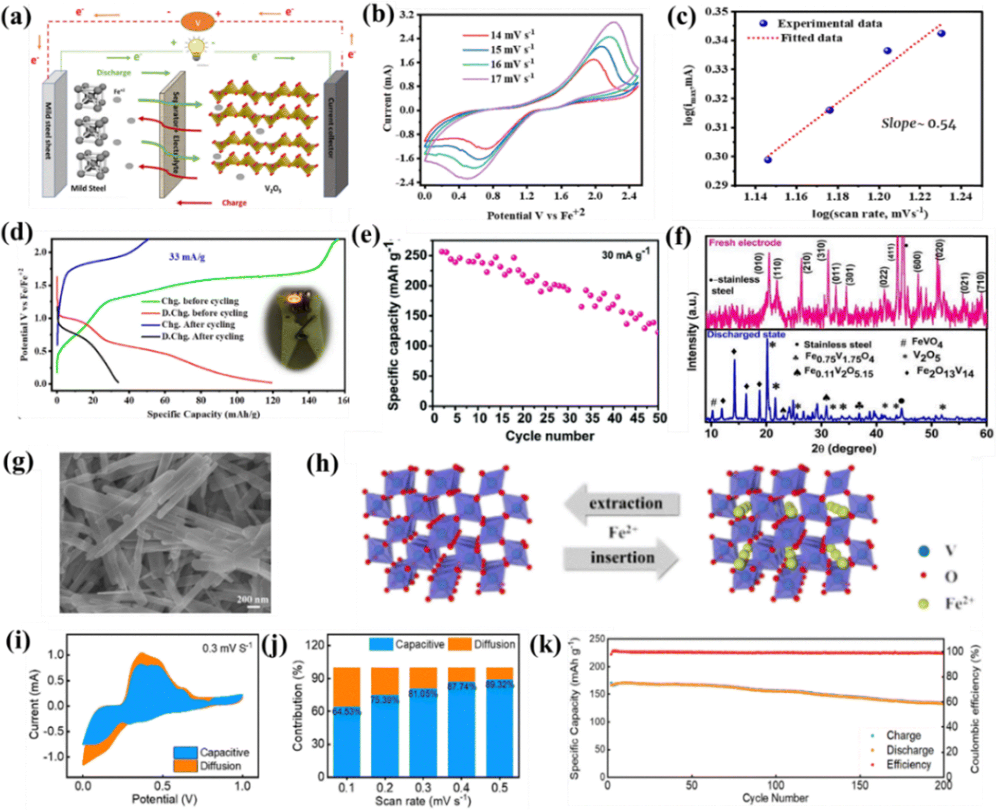 | ||
| Fig. 5 A non-aqueous Fe-ion battery based on the V2O5 cathode fabricated under ambient conditions. (a) Charging–discharging mechanism. (b) CV plot at various scan rates. (c) log(scan rate) vs. log (max current). (d) Voltage vs. specific capacity at 33 mA g−1.104 (e) Specific capacity vs. cycle number for non-aqueous Fe-ion battery which is fabricated in inert conditions using V2O5 cathode. (f) ex situ XRD measurements of V2O5 electrode.103 (g) SEM image of tunnel-like VO2. (h) Mechanism of Fe-ion extraction and insertion in VO2. (i) Capacitive and diffusive curve at 0.3 mV s−1. (j) Capacitive and diffusive percentage at various scan rates. (k) Specific capacity vs. cycle number at 2 A g−1 for the VO2 based cathode.101 | ||
Recently, Xu et al. explored tunnel-like VO2 as the cathode material for the aqueous rechargeable Fe-ion batteries based on 3 M Fe(OTF)2. Fig. 5(g) shows the SEM image of tunnel-like VO2, and Fig. 5(h) shows the crystal structure of VO2, which extracts and inserts Fe2+ ions during charging–discharging cycles. A detailed capacitive or diffusive behavior is also investigated to check whether the process is capacitive or diffusive. Fig. 5(i) shows the CV plot for capacitive and diffusive process at 0.3 mV s−1, the capacitive behavior is more dominant than the diffusive behavior and the percentage contribution is also shown in Fig. 5(j). A detailed GCD analysis indicates a specific capacity of 198 mA h g−1 at 0.2 A g−1 and a capacity of ∼160 mA h g−1 at a high current rate of 0.5 A g−1 with a capacity retention of 79% in 200 cycles, as shown in Fig. 5(k). The ex situ measurement of the VO2 electrodes was also done at various charge and discharge states, showing no phase transformation during cycling.101 Thus, the overall findings suggest the high electrochemical performance of the vanadium oxides (V2O5 & VO2) cathodes, where V2O5 is more favorable for the diffusive and VO2 is more favorable for the capacitive process in non-aqueous and aqueous electrolytes, respectively.
Vanadium(V) phosphate-based cathode materials were explored as efficient host cathodes in aqueous rechargeable Fe-ion batteries. Xu et al. reported VOPO4·2H2O as the cathode material. When VOPO4·2H2O comes into contact with an electrolyte, Fe2+ ions are trapped in the layered structure of VOPO4 and oxidized to Fe3+, and vanadium is reduced to the lower state at the open circuit potential. This Fe-bolted VOPO4·2H2O helps in the storage of Fe2+ ions via insertion and de-insertion mechanisms during reversible GCD cycling. A detailed schematic is shown in Fig. 6(a). VOPO4·2H2O was synthesized using the reflux method and confirmed by the morphology and structure via SEM and XRD, as shown in Fig. 6(b) and (c), respectively. The cell shows a specific capacity of 100 mA h g−1 at a current density of 1C along with an average discharge potential of 0.6 V. The cell was also cycled at a higher current density of 8C, showing a capacity retention of 68% in 800 cycles, as shown in Fig. 6(d).93 Recently, Li et al. reported phenylamine (PA) intercalated VOPO4 (PA–VOPO4) with large interlayer spacing, exhibiting improved electrochemical performance for aqueous Fe-ion batteries. PA was mainly introduced to increase the interlayer spacing between the VOPO4 layers, which increases the overall diffusion of the Fe2+ ion along with fast kinetics. A detailed crystal structure of VOPO4 and PA–VOPO4 is shown in Fig. 6(e). Fig. 6(f) shows the SEM image of VOPO4, exhibiting a narrow interlayer spacing, and the SEM image of PA–VOPO4 with large interlayer spacing is shown in Fig. 6(g). The synthesized PA–VOPO4 shows a more capacitive behavior than the diffusive for Fe2+ storage, where the percentage contribution of diffusive and capacitive behaviors are also shown in Fig. 6(h). It delivers high GCD performance with a specific capacity of 170 mA h g−1 at 0.2 A g−1, as shown in Fig. 6(i). Further, a cell was cycled at a higher current density of 1 A g−1 and showed a high capacity retention of 96% in 2200 cycles.100 These findings demonstrate the potential of vanadium-based cathode materials for the high performance of Fe-ion batteries. Further, via regulating the interlayer spacing of the materials can enhance the electrochemical performance of Fe-ion batteries. Meanwhile, more studies are needed to explore the potential of nanostructured vanadium oxide- and vanadium phosphate-based cathode materials for rechargeable Fe-ion batteries.
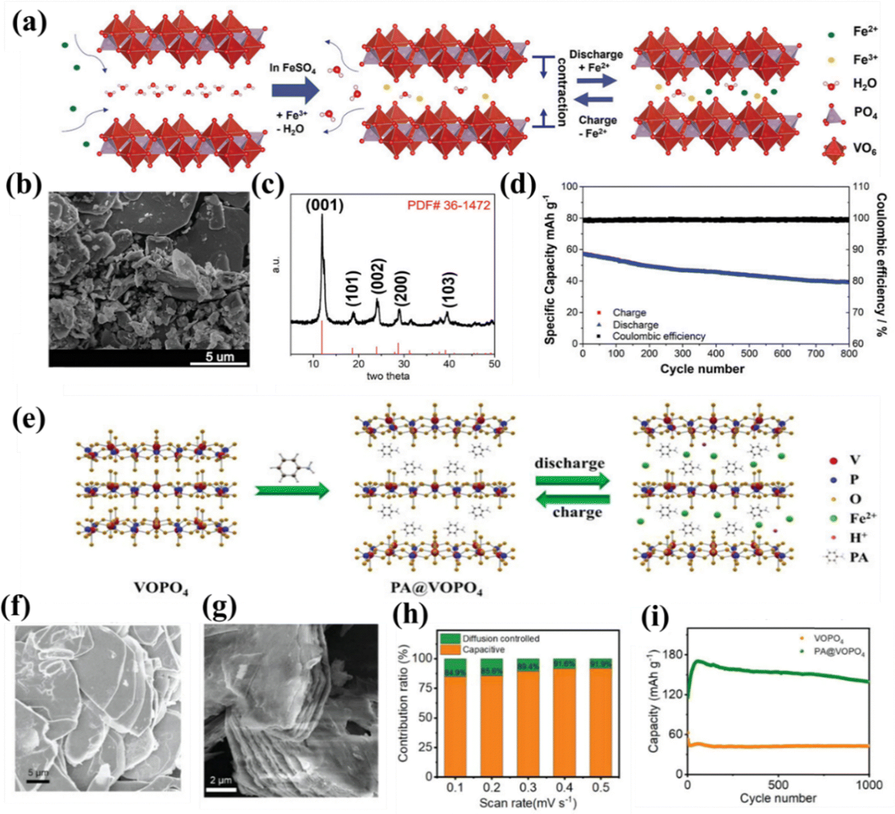 | ||
| Fig. 6 (a) Fe3+ bolted into the crystal structure of VOPO4·2H2O with the charging–discharging mechanism of Fe2+ ions. (b) SEM image of VOPO4·2H2O. (c) XRD pattern of VOPO4·2H2O. (d) Cycle number vs. capacity of Fe2+ storage at 8C.93 (e) Crystal structure of VOPO4 and PA–VOPO4 along with the Fe2+ ions storage into the crystal structure during charge–discharge mechanism. (f) SEM image of VOPO4. (g) SEM image of PA–VOPO4. (h) Contribution ratio (%) vs. scan rate plot for capacitive and diffusive process. (i) Capacity vs. cycle number at 200 mA g−1.100 | ||
4.2 Prussian blue analogues
The Prussian blue analogues are promising cathode materials due to their low cost and high theoretical capacity, including open framework structures.119 Wu et al. reported an iron-based insoluble Prussian blue analogue (Fe-PBA, Fe[Fe(CN)6]0.75·3.5H2O) cathode for aqueous rechargeable Fe-ion battery with a 0.5 M FeSO4 electrolyte. Fig. 7(a) shows the charging–discharging mechanism of Fe-PBA, which shows that the discharging Fe anode will oxidize and Fe2+ ions will be stored via the insertion/de-insertion mechanism in the Fe-PBA lattice. The Fe-PBA synthesized via a simple precipitation method exhibited a FCC structure as confirmed by XRD and contained Fe-PBA NPs with an average size of 50 nm, as shown in the inset TEM image of Fig. 7(b). A detailed electrochemical analysis was performed at various current densities in three electrodes and an entire coin cell. Fig. 7(c) shows specific capacity with cycle number at different current rates for the Fe-PBA with Fe anode-based full coin cells. The specific capacity varies from 60 mA h g−1 to 30 mA h g−1 at the current rate of 4C to 40C. The 10C rate shows a capacity retention of 80% and CE ∼99.3% in 1000 cycles along with a high average discharge potential of 0.72 V. These results were also compared with the MnO2-, V2O5-, and FePO4-based cathodes. Among these, Fe-PBA cathode materials show the most promising results. A hybrid battery was fabricated using a LiFePO4 cathode with an iron anode and a mixed iron and lithium-based salt electrolyte. The hybrid battery shows a specific capacity of 155 mA h g−1 at 1C along with a high discharge plateau of 0.8 V, showing the potential of Fe-ion batteries even in the form of Fe metal-based hybrid batteries.92 Recently, Huang et al. reported a magnesium substituted Prussian blue analogue (MgFeHCF) as an efficient cathode for the aqueous-based electrolyte. MgFeHCF was synthesized using the co-precipitation method and its FCC structure was confirmed via XRD and the nanocubes as observed from SEM/TEM are shown in Fig. 7(d) and (e). It shows nanocubes with a high specific capacity of 96 mA h g−1 at a current density of 0.2 A g−1 with a cyclic stability of 70% and an average CE of 98% in 500 cycles. It is relatively high compared to that without a Mg-substituted FeHCF cathode, as shown in Fig. 7(f). Further, in situ XRD measurement, impedance analysis, and DFT calculation-based performance assessment was also done, which suggests the low volume strain during cycling. Overall, Mg substituted in FeHCF stabilizes the structure and enhances the electrical and ionic conductivity, which is responsible for high GCD performance.96 Further, the electrochemical performance of PBAs can further be enhanced by doping of various cations according to the desired properties.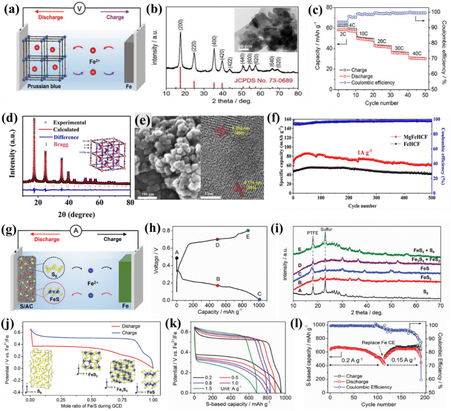 | ||
| Fig. 7 Prussian blue-based cathode. (a) Charging–discharging mechanism. (b) XRD pattern of IPB with the inset showing the TEM image. (c) GCD performance at various current rates.92 (d) XRD pattern of MgFeHCF. (e) SEM and TEM image of MgFeHCF. (f) GCD performance comparison at 1 A g−1 for MgFeHCF and FeHCF.96 S/AC based cathode. (g) Charge–discharge process. (h) Voltage curve with capacity. (i) XRD pattern at different charge–discharge voltage points mentioned in previous figure (h). (j) Charge–discharge with mole ratio of Fe/S. (k) Voltage vs. capacity at various current densities. (l) Capacity and CE with cycle number at different current densities.94 | ||
4.3 Sulfur-based cathode
Sulfur is abundant and environmentally friendly, making it a cost-effective and sustainable choice compared to some rarer battery materials. Sulfur has a high theoretical capacity exceeding 800 mA h g−1, nearly five times that of conventional cathodes. During cycling, sulfur undergoes multi-electron transfer reactions, leading to higher energy densities than that achieved with single-electron transfer in other materials.120,121 Wu et al. explored sulfur for the first time as the cathode material in aqueous Fe-ion batteries with pure sulfur and various sulfur/activated carbon (S/AC) composites. The study shows that sulfur works as the cathode without polysulfide shuttling during cycling. The solubility of iron and iron sulfides is negligible in aqueous solution compared to the solubility of lithium sulfide and sodium sulfide.122–124Fig. 7(g) shows the charge–discharge mechanism for the sulfur/activated carbon-based cathode. The Fe2+ ion storage mechanism was investigated at different charge–discharge states via XRD analysis. The charge–discharge curves are shown in Fig. 7(h), and the corresponding XRD plots at different states are shown in Fig. 7(i). The investigation shows solid phase transformations of S8 ↔ FeS2 ↔ Fe3S4 ↔ FeS without shuttling, as shown in Fig. 7(j). Further, electrochemical performance was investigated at different current rates based on the Fe anode and the S/AC-40 cathode, as shown in Fig. 7(k). The Fe anode and the S/AC-40 cathode exhibits a specific capacity of 632 mA h g−1 in 80 cycles with a capacity retention of 95% and CE ∼99.8% at a current rate of 0.2 A g−1. The capacity is recovered if the Fe counter electrode is replaced, as shown in Fig. 7(l). Overall, these studies show the potential of sulfur as an efficient cathode for aqueous Fe-ion batteries without polysulfide shuttling, a common problem with lithium/sodium ion batteries.944.4 PANI-based cathode materials
Polyaniline (PANI) is a conducting polymer that has been explored as the cathode materials for aqueous rechargeable Fe-ion batteries. Its abundance, low cost, flexibility, high conductivity, redox activity, and compatibility with aqueous electrolytes make it an attractive choice for developing cost-effective and sustainable energy storage solutions for multivalent metal-ion batteries.125 Wu et al. explored PANI as the cathode in aqueous rechargeable iron-iodine batteries, where PANI polyiodide shows high electrochemical performance at various current rates. It offers a discharge capacity of 2 mA h cm−2 (444 mA h g−1) without degradation in 1200 cycles with an average CE ∼98% at 8 mA cm−2.114 Zhang et al. explored PANI as the cathode for aqueous metal dual-ion batteries. The PANI cathode was assembled with an FeSO4 aqueous electrolyte, and modified MXene/Fe anode shows a specific capacity of 46 mA h g−1 at a current rate of 200 mA g−1 for 50 cycles.95 Li et al. reported an aqueous iron-organic battery based on the PANI cathode. Fig. 8(a) shows the SEM image of the PANI with a granular shape of 50 nm average size. The PANI cathode was assembled with the Fe anode and aqueous electrolyte to check the electrochemical performance. CV measurements were done at various scan rates, 0.5 mV s−1 to 1 mV s−1 with an interval of 0.1 mV s−1, as shown in Fig. 8(b). Using the power law, its suggests that surface-controlled behavior dominates the charge storage mechanism along with the fast kinetics. The cell exhibits a high GCD performance of 105.8 mA h g−1 at a current rate of 50 mA g−1, at a higher current density of 200 mA g−1 its shows the high stability for 5000 cycles along with an average CE of ∼99%, as shown in Fig. 8(c). A detailed computational study also showed the interaction between the PANI and CF3SO3− ions, substantiating the experimental findings.99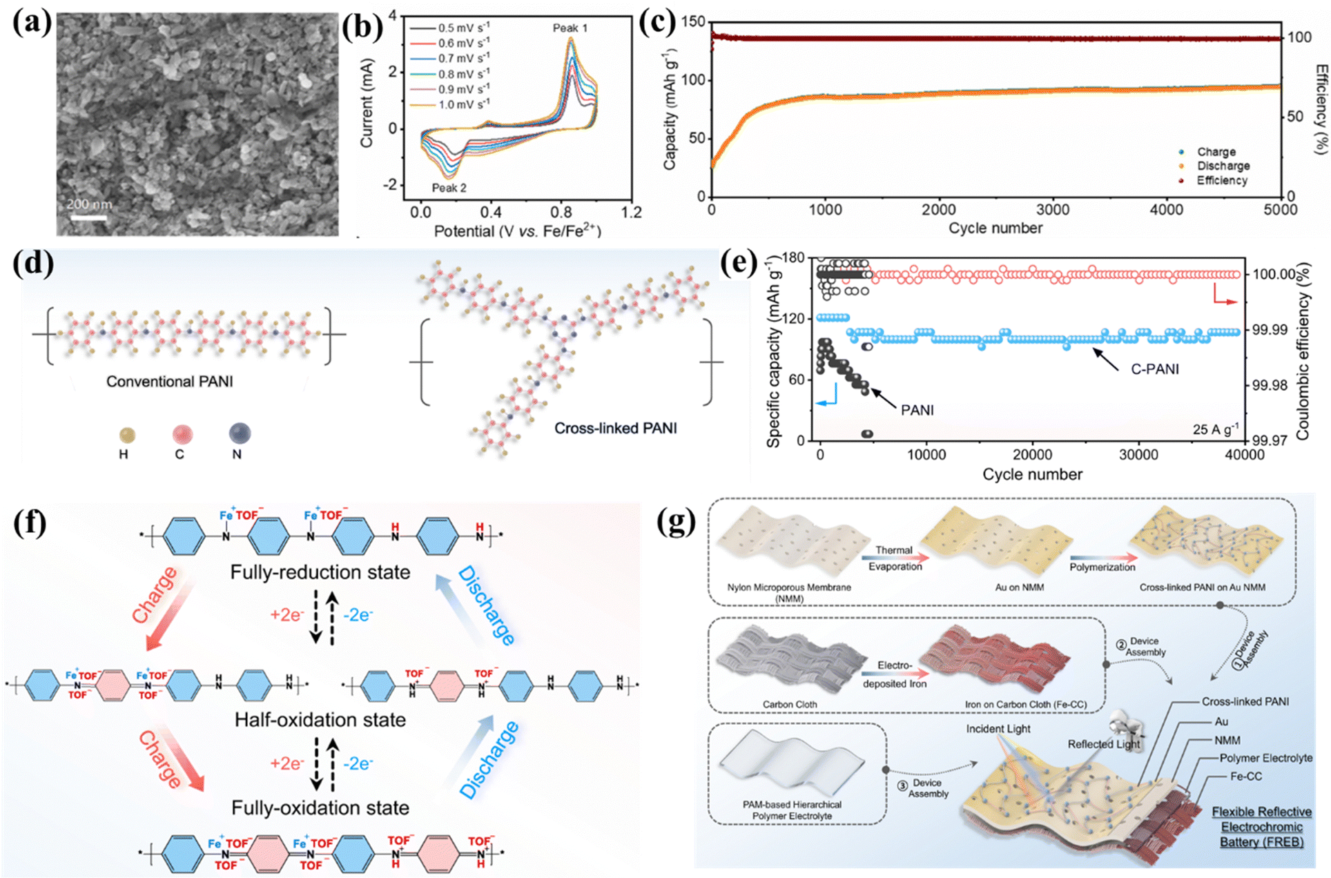 | ||
| Fig. 8 (a) SEM image of PANI. (b) CV plot at different scan rates. (c) Capacity and CE vs. cycle number at 0.2 A g−1.99 (d) schematic of conventional PANI and C-PANI. (e) GCD cycling performance of PANI vs. C-PANI in aqueous electrolyte. (f) Schematic of the charge storage mechanism via C-PANI. (g) Synthesis schematic of FREBs.108 | ||
Further, Lv et al. synthesized cross-linked polyaniline via an in situ chemical oxidative polymerization technique and explored it as an efficient cathode material as shown in Fig. 8(d). The PANI and cross-linked PANI (C-PANI) structure was confirmed and distinguished via various experimental tools, including FTIR, UV-Vis spectra, and high-resolution XPS spectra. A coin cell was assembled with a C-PANI cathode, an Fe anode, and an aqueous 1 M Fe(TOF)2 electrolyte. Detailed electrochemical characterization was conducted, and it was suggested that the C-PANI cathode has a higher GCD performance than the PANI cathode. It exhibits a specific capacity of 107 mA h g−1 at a current density of 25 A g−1 with a capacity retention of 84% in 39000 cycles, as shown in Fig. 8(e). The detailed analysis of the charge storage mechanism of C-PANI was also carried out using various characterization tools, including in situ Raman spectra, ex situ characterization, X-ray photoelectron spectroscopy (XPS), etc. The investigations show the charge storage mechanism given by both H+ storage and the Fe2+ ions storage process, where Fe2+ ions bonded with CH3SO3− ions and formed mixed cation Fe(TOF)+, as shown in Fig. 8(f). This unique charge storage mechanism provides fast kinetics because it reduces the charge densities of Fe2+, and electrostatic interaction will be lower with host materials, which enhances the performance. Further, a flexible reflective electrochromic battery (FREB) was also fabricated. Electrochromic devices are primarily used in aerospace applications where they can work to store energy together with electrochromic functions simultaneously. To fabricate the FREBs, electrodeposited Fe on CC used as the anode, C-PANI on Au NMM used as the cathode, and a PAM-based polymer electrolyte were used. The synthesis process is explained schematically in Fig. 8(g). A detailed electrochemical analysis shows 107 mA h g−1 capacity at 25 A g−1 current density with a capacity retention of 82% in 27000 cycles. This finding shows the potential of the C-PANI for the aqueous Fe-ion batteries.108 Additionally, more research should be dedicated to exploring other organic materials or composites as efficient cathode materials for rechargeable Fe-ion batteries.
4.5 Carbon-based cathode materials
Carbon-based cathode materials offer high electrical conductivity, promoting efficient charge and discharge in rechargeable metal-ion batteries. Their structural stability enhances cyclability, minimizing volume changes during repeated cycling for improved long-term performance. Carbon materials are often compatible with aqueous electrolytes, ensuring safety and environmental friendliness.126 Zhao et al. explored Fe-ion batteries based on the pure ionic liquid electrolyte, carbon-coated Fe, and carbon-reduced iron oxide along with the graphite-based anode. The cell exhibited a specific capacity of 20–100 mA h g−1 in various ionic liquid electrolyte-based systems.106 Chai et al. explored aqueous Fe-ion batteries based on carbon foam as the cathode as well as current collector, where carbon foam works as a host and provides Fe2+ ion adsorption/desorption, Fe2+/Fe3+ redox conversion and Fe3+ deposition. The cell was assembled using the Fe foam anode, a modified aqueous electrolyte, and carbon foam as the cathode. It exhibited an energy density of ∼240 mW h cm−3 and a power density of 12.1 W cm−3 with a capacity retention of 91% in 1000 cycles.111 Recently, the A-MAD research group explored the graphitic carbon nitride (g-C3N4) based cathode material for the non-aqueous Fe-ion batteries. Graphitic carbon nitride has enough spacing between the 2D layers to provide efficient intercalation/deintercalation of the Fe2+ ion during cycling. The charge–discharge mechanism of g-C3N4-based cathode materials is shown in Fig. 9(a). CV was investigated at 15 mV s−1 to check the reversible mechanism of the cathode along with the oxidation–reduction process, where the starting three cycles show that the process is highly reversible, as shown in Fig. 9(b). It shows a specific capacity of ∼130 mA h g−1 and 60 mA h g−1 at current density 40 and 400 mA g−1, respectively, as shown in Fig. 9(c). The cell exhibits fast charging–discharging characteristics at a high current density of 400 mA g−1 (∼3C), as shown in Fig. 9(d). It shows a high-capacity retention of more than 60% at 400 mA g−1 in 240 cycles, as shown in Fig. 9(e). A detailed ex situ analysis of the electrodes was carried out via XRD and SEM to understand the stability of g-C3N4. The XRD pattern suggests no phase changes, as shown in Fig. 9(f). These results are also consistent with the electrochemical impedance spectroscopy (EIS) analysis, as shown in Fig. 9(g). The demonstration was also performed using coin cells in series connected with LEDs, as shown in Fig. 9(h). These findings show the potential of g-C3N4-based cathode materials towards high-performance Fe-ion batteries.105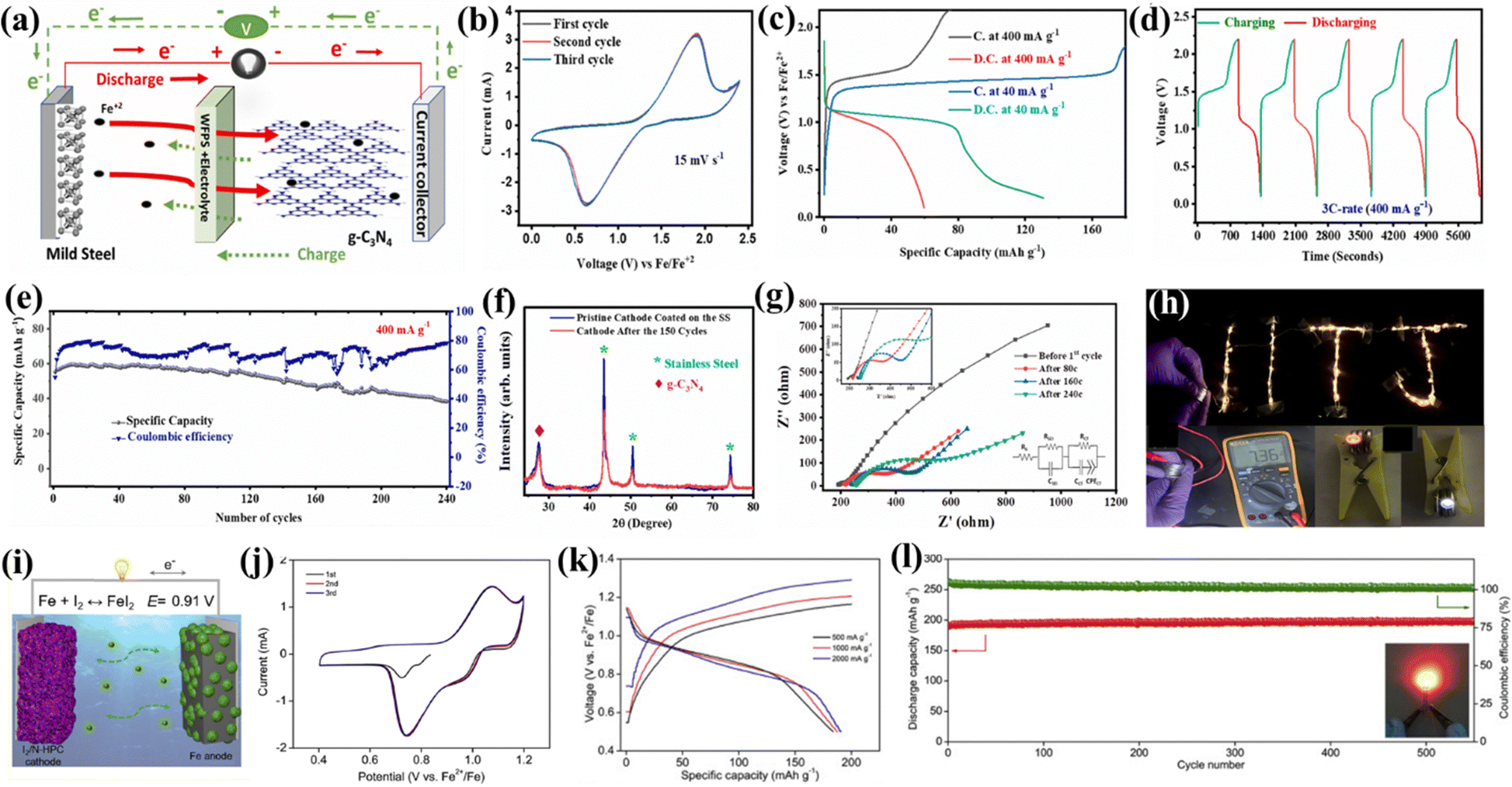 | ||
| Fig. 9 Graphitic carbon nitride cathode for Fe-ion batteries. (a) Charge–discharge mechanism. (b) CV diagram at 15 mV s−1. (c) Charge–discharge curve at 40 and 400 mA g−1. (d) Voltage vs. time profile at 3C rate. (e) Capacity and CE vs. cycle number at 3C. (f) Pre- and post-XRD pattern of g-C3N4. (g) Nyquist plot of EIS at the different cycling with an inset fitted equivalent circuit. (h) Demonstration of the Fe-ion full coin cell based on the g-C3N4 cathode.105 Fe–I2 battery, (i) charge–discharge schematic. (j) CV plot at 0.05 mV s−1. (k) Charge–discharge curve at various current densities. (l) Capacity and CE vs. cycle number at 2 A g−1.97 | ||
Bai et al. explored high-power aqueous iron-iodine batteries based on the I2/nitrogen-doped hierarchically porous carbon (N-HPC) composite cathode. The coin cell was fabricated together with a Fe foil anode and an aqueous electrolyte. A schematic diagram of charge–discharge is shown in Fig. 9(i). CV analysis suggests the reaction reversibility for the starting three cycles, the weak reduction peak at 1 V indicates the capacitive behavior of N-HPC, as shown in Fig. 9(j). Further GCD analysis was done to check the capacity and electrode stability. The cell exhibits a high specific capacity of 180 to 190 mA h g−1 at various current rates, as shown in Fig. 9(k). The cell also cycles at a high current rate of 2 A g−1, showing very high capacity retention along with an average CE of ∼99% in more than 550 cycles, as shown in Fig. 9(l).97 Zhang et al. reported dual heteroatoms, i.e., N, P, and FeP nanocrystals, which were integrated into a carbon shell-based cathode for high-performance aqueous iron-iodine batteries. Here, the porous carbon core–shell material prevents the dissolution of the iodine species. The cell was fabricated with N, P dual heteroatoms, FeP nanocrystals/carbon shell cathode, iron metal anode, and aqueous electrolyte. The cell exhibited a specific capacity of 202 mA h g−1 with an excellent capacity retention of 92% for more than 500 cycles. The charge storage mechanism reaction was investigated using various tools, including electrochemical, Raman spectra, and XPS analysis.98
5. Anode materials
The metal anode should have a low overpotential for the deposition and stripping of multivalent metal ions during cycling. A low overpotential helps minimize energy losses and improve the efficiency of battery. Iron or iron-based compounds serve as the anode materials for rechargeable aqueous and non-aqueous Fe-ion batteries. The electroplating/stripping process takes place during the charging–discharging process. In the charging process, the iron anode undergoes electroplating, where iron ions in the electrolyte are reduced and deposited onto the surface of anode. In the discharging process, iron ions are oxidized and released into the electrolyte, also called the electro-stripping process. Mild steel contains more than 99% Fe, and is used as an anode in non-aqueous Fe-ion batteries.103–105 High-purity iron foil, iron plates, Fe foam, or iron sheets are widely used as anode materials in various aqueous Fe-ion batteries.96,98–100,108,111,113,114,127 Iron nanoparticle powder was also used as the anode material after mixing with a binder and carbon-based conducting agent, as reported in various findings for aqueous Fe-ion batteries.92–94 All the anode materials used in Fe-ion batteries for the non-aqueous and aqueous electrolytes are also summarized in Tables 1 and 2, respectively. The A-MAD research group recently reported a detailed capacity degradation analysis of the non-aqueous Fe-ion batteries, suggesting that the formation of an oxidation layer during cycling at the anode hinders the battery's performance. Fig. 10(a) shows the optical picture of the pristine mild steel and cycled mild steel along with SEM analysis, which shows the oxide layer formation at the mild steel during cycling. The XRD pattern of the cycled mild steel at various cycle stages is shown in Fig. 10(b), which suggests the passivation of the iron oxide layer during cycling, which decreases the performance.105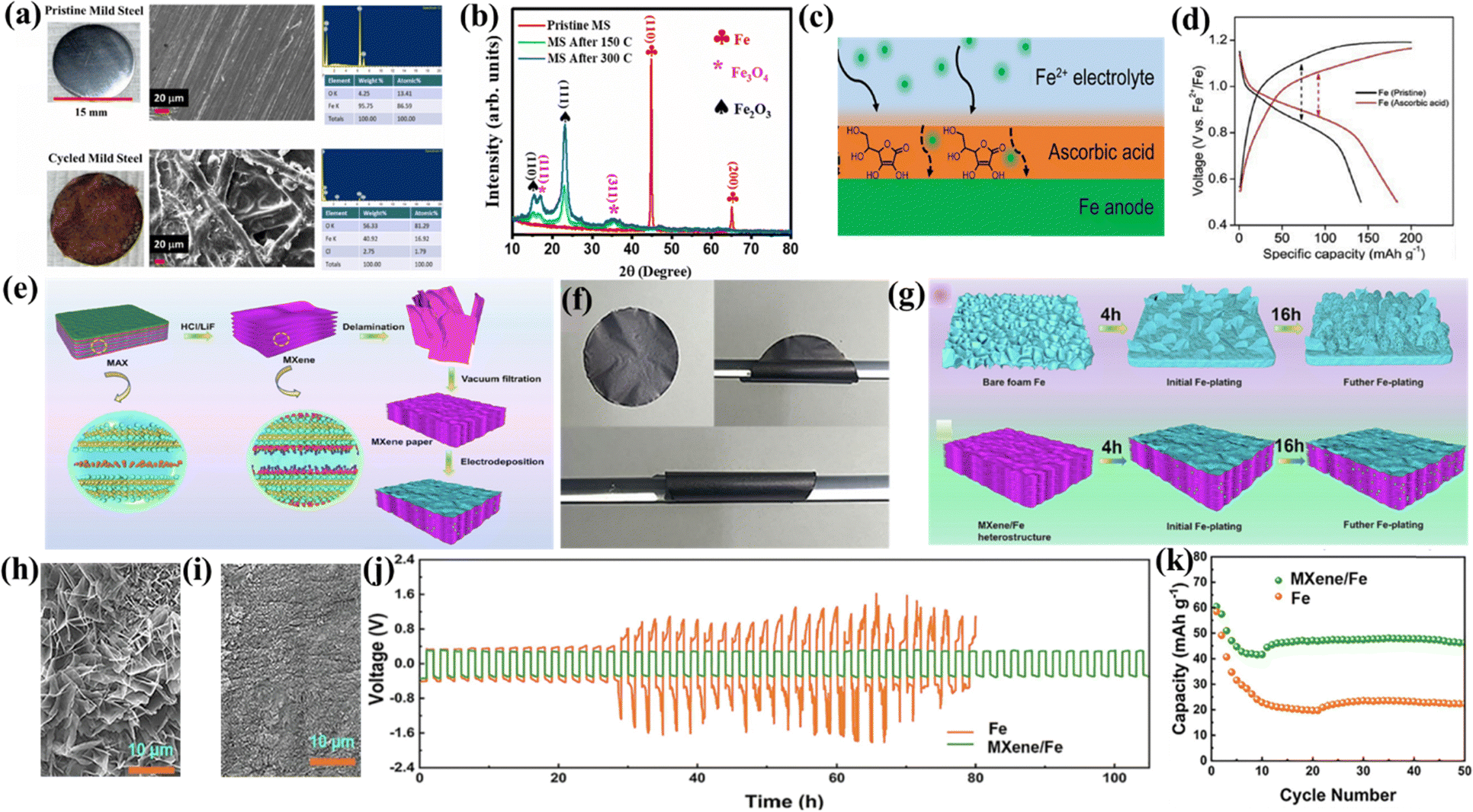 | ||
| Fig. 10 (a) SEM and optical image of pre- and post-mild steel. (b) XRD pattern of the pristine and cycled mild steel.105 (c) Schematic of the ascorbic acid treated Fe anode. (d) Voltage vs. capacity profile at 500 mA g−1.97 (e) Synthesis process of flexible MXene/Fe. (f) Flexibility test of MXene paper. (g) Schematic presentation of Fe deposition on Fe foam and MXene paper. SEM image of (h) MXene/Fe electrodeposited for 16 h and (i) Fe foam/Fe electrodeposited for 16 h. (j) Voltage vs. time profile during Fe electroplating/stripping for Fe and MXene/Fe. (k) Capacity with cycle number of Fe and MXene/Fe.95 | ||
Further, various techniques were developed to reduce the passivation or dendrite formation at the anode and enhance its CE without degradation in aqueous electrolytes. Bai et al. modified the anode with ascorbic acid (chelating agent) to suppress the formation of dendrites or the passivation layer. The schematic shows the modified iron with electrolyte in Fig. 10(c). Detailed performance analysis of the anode and the modified anode was done using GCD analysis, where the modified iron anode contained Fe powder, which was treated with 0.2 M ascorbic acid for 12 h, and the slurry was formed using a binder and a carbon conductive agent. Fig. 10(d) shows the charge–discharge profile, which exhibits a higher specific capacity and lesser voltage hysteresis for the modified anode due to the ascorbic acid layer, which enhances the electrochemical performance. A detailed SEM analysis was also performed for the modified anode before and after cycling.97
Zhang et al. developed an efficient, flexible MXene/Fe heterostructure as the high-performance anode for aqueous Fe-ion batteries. The MXene/Fe structure effectively suppresses dendrite formation and improves the Fe plating–stripping kinetics during cycling. Fig. 10(e) presents a detailed synthesis schematic of MXene and MXene paper using vacuum filtration. The flexibility was tested by bending the MXene paper, as shown in Fig. 10(f). Fe was electrodeposited on the surface of the flexible MXene paper via 0.5 M FeSO4 solution with Fe foam as the counter and reference electrode for up to 16 h to use the MXene as the anode material. Similarly, Fe was also electrodeposited on the bare Fe foam under identical conditions to show the difference between both the materials, as shown in Fig. 10(g). The SEM image was obtained for electrodeposited Fe on the bare Fe foam and MXene/Fe after 16 h to analyze the surface morphology, suggesting that flaky type dendrites were formed on the surface of the bare Fe foam, where MXene paper works as a 3D host, which hinders the growth of dendrites, as shown in Fig. 10(h) and (i), respectively. Electrochemical measurements were done by fabricating the symmetric coin cell with the bare Fe foam and the modified anode based on MXene/Fe using 1 M FeSO4 electrolyte. Fig. 10(j) shows the potential vs. time profile during the electroplating/stripping process for more than 100 h, suggesting that MXene/Fe is the more stable interface with the aqueous electrolyte along with the stable curve and lower overpotential. Further, the full coin cell was GCD tested using a PANI-based cathode along with the Fe and MXene/Fe-based anode, showing higher specific capacity for the MXene/Fe-based anode with higher cycling stability, as shown in Fig. 10(k). These findings provide an effective method for suppressing dendrite formation and hydrogen evolution reactions in aqueous systems with the selection of suitable anode material.95
6. Challenges and perspectives
Rechargeable Fe-ion batteries possess enticing advantages like affordability, safety, and environmental sustainability, yet face several hurdles before widespread adoption. The associated challenges with rechargeable Fe-ion batteries are summarized below.• The main challenge is the relatively low energy density and cyclic stability along with the lower discharge voltage plateau of cathode materials for Fe-ion batteries. These issues can be addressed by developing novel nanoengineered cathode materials with open frameworks, increased surface area, and optimized pore structure to facilitate faster Fe2+ ion diffusion and improve rate performance. The electrochemical performances can also be enhanced by regulating the interlayer spacing and surface engineering of various cathode materials to enhance the effectiveness of charge storage mechanisms through the intercalation/deintercalation of Fe2+ ions.
• Another challenge with the Fe anode in the aqueous electrolyte is its low coulombic efficiency due to the side reactions, dendrite growth, formation of the passivation layer, and H2 evolution in the aqueous medium at the Fe metal anode. It can be addressed by introducing various techniques, including nanostructured Fe, surface coating on Fe, interface engineering, cation doping, and electrolyte additives. Coating electrodes with protective layers or modifying their surface chemistry can hinder unwanted reactions and improve the stability of the Fe anode. Tailoring the interface between electrodes and electrolytes is crucial for minimizing side reactions and improving cyclability. Overall, these approaches can suppress H2 evolution and overpotential and increase the efficiency and cyclability of the Fe anode.
• The problem with the electrolyte is that conventional aqueous electrolytes show low ionic conductivity and a lower operating voltage window and sometimes incompatible with electrodes materials in rechargeable Fe-ion batteries. It can be addressed by electrolyte modification via developing an electrolyte with higher ionic conductivity and optimizing various Fe2+ salt and solvent compositions. Electrolyte additives can enhance the mobility of Fe2+ ions and improve charging/discharging rates by suppressing side reactions at the anode side. Solid-state electrolytes based on Fe should also be explored to overcome these issues, but these have limited ionic conductivity, which can be further tried at higher temperature-based Fe-ion batteries. All the challenges and corresponding perspectives for the electrodes and electrolytes are also summarised in Fig. 11. Thus, these Fe-ion batteries can potentially revolutionize the energy storage landscape by offering a sustainable, affordable, and safe alternative to existing technologies by addressing all these challenges.
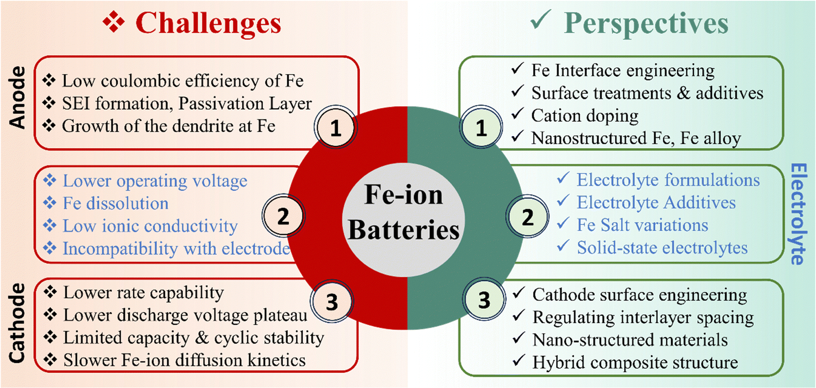 | ||
| Fig. 11 Challenges and corresponding perspectives related to the different components of rechargeable Fe-ion batteries. | ||
7. Conclusions
In conclusion, rechargeable Fe-ion batteries are economically attractive due to the abundance of iron and its low cost. They boast higher energy density, promising improved energy storage capabilities. Safety profile of iron reduces the concerns related to thermal runaway, thus enhancing overall safety and efficacy. This review article provides the recent evolutions in developing anode, cathode, and electrolyte materials, including the essential components, reaction mechanisms, and guidelines for selection of electrodes and electrolyte for efficient rechargeable iron-ion batteries. This article also highlights significant methodologies to improve electrochemical performance, such as adding electrolyte additives and electrodes modifications, followed by the current technical challenges and future directions. Despite the obstacles, Fe-ion batteries hold immense potential for the future of energy storage due to their inherent advantages. This study aims to establish a fundamental understanding of rechargeable Fe-ion batteries as a potential alternative for clean and green energy storage systems.Conflicts of interest
There are no conflicts to declare.Acknowledgements
Author Ambesh Dixit acknowledges SERB, DST, Govt. of India for the support through the project #CRG/2020/004023 and SERB/F/10090/2021-2022 for carrying out this work. The authors Jitendra Kumar Yadav, Bharti Rani, Priyanka Saini acknowledges the A-MAD research group for their technical assistance during the work.References
- T. A. Faunce, J. Prest, D. Su, S. J. Hearne and F. Iacopi, MRS Energy Sustainability, 2018, 5, 10 CrossRef.
- H. S. Das, M. M. Rahman, S. Li and C. W. Tan, Renewable Sustainable Energy Rev., 2020, 120, 109618 CrossRef.
- M. Kumar, B. Meena, A. Yu, C. Sun and S. Challapalli, Green Chem., 2023, 25, 8411–8443 RSC.
- W. Jung, J. Jeong, J. Kim and D. Chang, J. Power Sources, 2020, 451, 227754 CrossRef CAS.
- M. Kumar, B. Meena, P. Subramanyam, G. Ummethala, S. R. K. Malladi, S. Dutta-Gupta and C. Subrahmanyam, Energy Fuels, 2023, 37, 2340–2349 CrossRef CAS.
- P. Saini, J. K. Yadav, B. Rani, A. P. Pandey and A. Dixit, Energy Storage, 2024, 6, e608 CrossRef CAS.
- T. M. Gür, Energy Environ. Sci., 2018, 11, 2696–2767 RSC.
- M. Kumar, C. C. Ghosh, B. Meena, T. Ma and C. Subrahmanyam, Sustainable Energy Fuels, 2022, 6, 3961–3974 RSC.
- L. Wei, L. Zeng, M. C. Wu, H. R. Jiang and T. S. Zhao, J. Power Sources, 2019, 423, 203–210 CrossRef CAS.
- H. Gupta, Y. Dahiya, H. K. Rathore, K. Awasthi, M. Kumar and D. Sarkar, ACS Appl. Mater. Interfaces, 2023, 15, 42685–42696 CrossRef CAS PubMed.
- R. Yadav, N. Macherla, K. Singh and K. Kumari, Engineering Proceedings, 2023, 59, 175 Search PubMed.
- S. Lee, J. Hong and K. Kang, Adv. Energy Mater., 2020, 10, 2001445 CrossRef CAS.
- P. Saini, B. Rani, J. K. Yadav, P. Choudhary, P. Sahoo and A. Dixit, in Energy Materials and Devices. E-MAD 2022. Advances in Sustainability Science and Technology, ed. A. Dixit, V. K. Singh and S. Ahmad, Springer Nature Singapore, Singapore, 2024, pp. 125–136 Search PubMed.
- J. K. Yadav, B. Rani, A. Tiwari and A. Dixit, J. Renewable Sustainable Energy, 2024, 16, 014101 CrossRef CAS.
- M. Kumar, B. Meena, P. Subramanyam, D. Suryakala and C. Subrahmanyam, Catalysts, 2022, 12, 1198 CrossRef CAS.
- B. Mondal, A. Azam and S. Ahmad, Energy Fuels, 2023, 37, 16105–16118 CrossRef CAS.
- C. Liu, F. Li, M. Lai-Peng and H. M. Cheng, Adv. Mater., 2010, 22, 28–62 Search PubMed.
- A. Dixit, Soc. Mater. Chem., 2020, 10, 151–166 Search PubMed.
- K. Bazzi, K. S. Dhindsa, A. Dixit, M. B. Sahana, C. Sudakar, M. Nazri, Z. Zhou, P. Vaishnava, V. M. Naik, G. A. Nazri and R. Naik, J. Mater. Res., 2012, 27, 424–430 CrossRef CAS.
- M. Armand, P. Axmann, D. Bresser, M. Copley, K. Edström, C. Ekberg, D. Guyomard, B. Lestriez, P. Novák, M. Petranikova, W. Porcher, S. Trabesinger, M. Wohlfahrt-Mehrens and H. Zhang, J. Power Sources, 2020, 479, 228708 CrossRef CAS.
- C. M. Costa, J. C. Barbosa, R. Gonçalves, H. Castro, F. J. D. Campo and S. Lanceros-Méndez, Energy Storage Mater., 2021, 37, 433–465 CrossRef.
- J. K. Yadav, B. Tiwari and A. Dixit, in Energy Materials and Devices. E-MAD 2022. Advances in Sustainability Science and Technology, ed. A. Dixit, V. K. Singh and S. Ahmad, Springer Nature Singapore, Singapore, 2024, pp. 35–47 Search PubMed.
- E. Goikolea, V. Palomares, S. Wang, I. R. de Larramendi, X. Guo, G. Wang and T. Rojo, Adv. Energy Mater., 2020, 10, 2002055 CrossRef CAS.
- R. Sahoo, M. Singh and T. N. Rao, ChemElectroChem, 2021, 8, 2358–2396 CrossRef CAS.
- X. Zhang, T. Xiong, B. He, S. Feng, X. Wang, L. Wei and L. Mai, Energy Environ. Sci., 2022, 15, 3750–3774 RSC.
- X. Shi, Z. Xu, Y. Tang, Y. Zhao, B. Lu and J. Zhou, Appl. Phys. Lett., 2023, 123, 041903 CrossRef CAS.
- P. Vaghela, V. Pandey, A. Sircar, K. Yadav, N. Bist and R. Kumari, MRS Energy Sustainability, 2023, 10, 261–276 CrossRef.
- H. Gupta, M. Kumar, D. Sarkar and P. W. Menezes, Energy Adv., 2023, 2, 1263–1293 RSC.
- R. M. Dell and D. A. J. Rand, J. Power Sources, 2001, 100, 2–17 CrossRef CAS.
- J. Xie and Q. Zhang, Small, 2019, 15, 1–20 Search PubMed.
- Y. Liang, H. Dong, D. Aurbach and Y. Yao, Nat. Energy, 2020, 5, 646–656 CrossRef CAS.
- M. A. Schroeder, L. Ma, G. Pastel and K. Xu, Curr. Opin. Electrochem., 2021, 29, 100819 CrossRef CAS.
- K. F. Blurton and A. F. Sammells, J. Power Sources, 1979, 4, 263–279 CrossRef CAS.
- Q. Liu, Z. Pan, E. Wang, L. An and G. Sun, Energy Storage Mater., 2020, 27, 478–505 CrossRef.
- J. Yu, B.-Q. Li, C.-X. Zhao and Q. Zhang, Energy Environ. Sci., 2020, 13, 3253–3268 RSC.
- P. Alotto, M. Guarnieri and F. Moro, Renewable Sustainable Energy Rev., 2014, 29, 325–335 CrossRef CAS.
- I. Iwakiri, T. Antunes, H. Almeida, J. P. Sousa, R. B. Figueira and A. Mendes, Energies, 2021, 14, 5643 CrossRef CAS.
- J. Shin, J. Lee, Y. Park and J. W. Choi, Chem. Sci., 2020, 11, 2028–2044 RSC.
- J. Ming, J. Guo, C. Xia, W. Wang and H. N. Alshareef, Mater. Sci. Eng., R, 2019, 135, 58–84 CrossRef.
- J. Li, Z. Liu, S. Han, P. Zhou, B. Lu, J. Zhou, Z. Zeng, Z. Chen and J. Zhou, Nanomicro Lett., 2023, 15, 237 CAS.
- X. Li, Z. Chen, P. Ruan, X. Hu, B. Lu, X. Yuan, S. Tian and J. Zhou, Nanoscale, 2024, 16, 2923–2930 RSC.
- B. Rani, J. K. Yadav, P. Saini, A. P. Pandey and A. Dixit, Energy Storage, 2024, 6, e586 CrossRef CAS.
- A. P. Pandey, B. Rani, M. Sharma, J. K. Yadav, P. Saini, Shalu and A. Dixit, Energy Storage, 2023, 6, e549 CrossRef.
- G. A. Elia, K. Marquardt, K. Hoeppner, S. Fantini, R. Lin, E. Knipping, W. Peters, J. Drillet, S. Passerini and R. Hahn, Adv. Mater., 2016, 28, 7564–7579 CrossRef CAS PubMed.
- M. Jiang, C. Fu, P. Meng, J. Ren, J. Wang, J. Bu, A. Dong, J. Zhang, W. Xiao and B. Sun, Adv. Mater., 2021, 34, 2102026 CrossRef PubMed.
- B. Rani, J. K. Yadav and A. Dixit, in Energy Materials and Devices. E-MAD 2022. Advances in Sustainability Science and Technology, ed. A. Dixit, V. K. Singh and S. Ahmad, Springer Nature Singapore, Singapore, 2024, pp. 91–101 Search PubMed.
- C. Zhou, K. Bhonge and K. T. Cho, Electrochim. Acta, 2020, 330, 135290 CrossRef CAS.
- J. Tu, W. L. Song, H. Lei, Z. Yu, L. L. Chen, M. Wang and S. Jiao, Chem. Rev., 2021, 121, 4903–4961 CrossRef CAS PubMed.
- H. Yang, H. Li, J. Li, Z. Sun, K. He, H. Cheng and F. Li, Angew. Chem., Int. Ed., 2019, 58, 11978–11996 CrossRef CAS PubMed.
- D. L. Huber, Small, 2005, 1, 482–501 CrossRef CAS PubMed.
- M. R. Palacín, Chem. Soc. Rev., 2009, 38, 2565–2575 RSC.
- C. Chakkaravarthy, P. Periasamy, S. Jegannathan and K. I. Vasu, J. Power Sources, 1991, 35, 21–35 CrossRef CAS.
- A. K. Shukla, M. K. Ravikumar and T. S. Balasubramanian, J. Power Sources, 1994, 51, 29–36 CrossRef CAS.
- P.-J. Tsais and L. I. Chan, Electricity Transmission, Distribution and Storage Systems, Elsevier, 2013, pp. 309–397 Search PubMed.
- D. Sarkar, A. Shukla and D. D. Sarma, ACS Energy Lett., 2016, 1, 82–88 CrossRef CAS.
- J. M. E. Abarro, J. N. L. Gavan, D. E. D. Loresca, M. A. A. Ortega, E. A. Esparcia and J. A. D. R. Paraggua, Batteries, 2023, 9, 383 CrossRef CAS.
- C. Morehouse, R. Glicksman and G. Lozier, Proc. IRE, 1958, 46, 1462–1483 CAS.
- J. Yang, J. Chen, Z. Wang, Z. Wang, Q. Zhang, B. He, T. Zhang, W. Gong, M. Chen, M. Qi, P. Coquet, P. Shum and L. Wei, ChemElectroChem, 2021, 8, 274–290 CrossRef CAS.
- A. Shukla, J. Power Sources, 2001, 100, 125–148 CrossRef CAS.
- R. Dell, Solid State Ion, 2000, 134, 139–158 CrossRef CAS.
- D. Lei, D.-C. Lee, A. Magasinski, E. Zhao, D. Steingart and G. Yushin, ACS Appl. Mater. Interfaces, 2016, 8, 2088–2096 CrossRef CAS PubMed.
- A. H. Abdalla, C. I. Oseghale, J. O. Gil Posada and P. J. Hall, IET Renew. Power Gen., 2016, 10, 1529–1534 CrossRef.
- H. Wang, Y. Liang, M. Gong, Y. Li, W. Chang, T. Mefford, J. Zhou, J. Wang, T. Regier, F. Wei and H. Dai, Nat. Commun., 2012, 3, 917 CrossRef PubMed.
- B. Liu, X. Liu, X. Fan, J. Ding, W. Hu and C. Zhong, J. Alloys Compd., 2020, 834, 155185 CrossRef CAS.
- T. Huang, W. Liu, Y. Liu, Q. Hou, S. Chen, R. Li and H. Liu, Next Energy, 2024, 2, 100076 CrossRef.
- M. Bartolozzi, J. Power Sources, 1989, 27, 219–234 CrossRef CAS.
- L. H. Thaller, Redox flow cell energy storage systems, NASA, 1979, TM-79143, DOE/NASA/1002-79/3.
- L. Öjefors and L. Carlsson, J. Power Sources, 1978, 2, 287–296 CrossRef.
- M. H. Chakrabarti, E. P. Lindfield Roberts and M. Saleem, Int. J. Green Energy, 2010, 7, 445–460 CrossRef CAS.
- M. H. Chakrabarti, R. A. W. Dryfe and E. P. L. Roberts, Electrochim. Acta, 2007, 52, 2189–2195 CrossRef CAS.
- B. T. Hang, T. Watanabe, M. Eashira, S. Okada, J. Yamaki, S. Hata, S.-H. Yoon and I. Mochida, J. Power Sources, 2005, 150, 261–271 CrossRef CAS.
- X. Ke, J. M. Prahl, J. I. D. Alexander, J. S. Wainright, T. A. Zawodzinski and R. F. Savinell, Chem. Soc. Rev., 2018, 47, 8721–8743 RSC.
- C. Sun and H. Zhang, ChemSusChem, 2021, 15, e202101798 CrossRef PubMed.
- A. Dinesh, S. Olivera, K. Venkatesh, M. S. Santosh, M. G. Priya, Inamuddin, A. M. Asiri and H. B. Muralidhara, Environ. Chem. Lett., 2018, 16, 683–694 CrossRef CAS.
- M. C. Tucker, A. Phillips and A. Z. Weber, ChemSusChem, 2015, 8, 3996–4004 CrossRef CAS PubMed.
- K. Gong, F. Xu, J. B. Grunewald, X. Ma, Y. Zhao, S. Gu and Y. Yan, ACS Energy Lett., 2016, 1, 89–93 CrossRef CAS.
- H. Zhang and C. Sun, J. Power Sources, 2021, 493, 229445 CrossRef CAS.
- S. Trocino, M. Lo Faro, S. C. Zignani, V. Antonucci and A. S. Aricò, Appl. Energy, 2019, 233–234, 386–394 CrossRef CAS.
- H. A. Figueredo-Rodríguez, R. D. McKerracher, M. Insausti, A. G. Luis, C. P. de León, C. Alegre, V. Baglio, A. S. Aricò and F. C. Walsh, J. Electrochem. Soc., 2017, 164, A1148–A1157 CrossRef.
- S. R. Narayanan, G. K. S. Prakash, A. Manohar, B. Yang, S. Malkhandi and A. Kindler, Solid State Ion, 2012, 216, 105–109 CrossRef CAS.
- R. D. McKerracher, C. Poncedeleon, R. G. A. Wills, A. A. Shah and F. C. Walsh, ChemPlusChem, 2015, 80, 323–335 CrossRef CAS.
- X. Zhao, N. Xu, X. Li, Y. Gong and K. Huang, RSC Adv., 2012, 2, 10163 RSC.
- Z. He, F. Xiong, S. Tan, X. Yao, C. Zhang and Q. An, Mater. Today Adv., 2021, 11, 100156 CrossRef CAS.
- J. Jiang and J. Liu, Interdisciplinary Mater., 2022, 1, 116–139 CrossRef.
- P. Peljo and H. H. Girault, Energy Environ. Sci., 2018, 11, 2306–2309 RSC.
- X. Zhao, X. Liang, Y. Li, Q. Chen and M. Chen, Energy Storage Mater., 2021, 42, 533–569 CrossRef.
- S. S. Manna, P. Bhauriyal and B. Pathak, Mater. Adv., 2020, 1, 1354–1363 RSC.
- H. Wang, D. Zhai and F. Kang, Energy Environ. Sci., 2020, 13, 4583–4608 RSC.
- E. M. Erickson, E. Markevich, G. Salitra, D. Sharon, D. Hirshberg, E. de la Llave, I. Shterenberg, A. Rosenman, A. Frimer and D. Aurbach, J. Electrochem. Soc., 2015, 162, A2424–A2438 CrossRef CAS.
- R. Demir-Cakan, M. R. Palacin and L. Croguennec, J. Mater. Chem. A, 2019, 7, 20519–20539 RSC.
- W. Manalastas, S. Kumar, V. Verma, L. Zhang, D. Yuan and M. Srinivasan, ChemSusChem, 2019, 12, 379–396 CrossRef CAS PubMed.
- X. Wu, A. Markir, Y. Xu, C. Zhang, D. P. Leonard, W. Shin and X. Ji, Adv. Funct. Mater., 2019, 29, 1900911 CrossRef.
- Y. Xu, X. Wu, S. K. Sandstrom, J. J. Hong, H. Jiang, X. Chen and X. Ji, Adv. Mater., 2021, 33, 2105234 CrossRef CAS PubMed.
- X. Wu, A. Markir, Y. Xu, E. C. Hu, K. T. Dai, C. Zhang, W. Shin, D. P. Leonard, K. il Kim and X. Ji, Adv. Energy Mater., 2019, 9, 1902422 CrossRef CAS.
- Y. Zhang, Y. Tian, Z. Wang, C. Wei, C. Liu, Y. An, B. Xi, S. Xiong and J. Feng, Chem. Eng. J., 2023, 458, 141388 CrossRef CAS.
- G. Huang, Z. Lao, Z. He, F. Xiong, S. Tan, M. Huang, G. Thompson, Q. An and L. Mai, Chem. Commun., 2023, 59, 4067–4070 RSC.
- C. Bai, H. Jin, Z. Gong, X. Liu and Z. Yuan, Energy Storage Mater., 2020, 28, 247–254 CrossRef.
- W. Zhang, M. Wang, H. Zhang, L. Fu, W. Zhang, Y. Yuan and K. Lu, Chem. Sci., 2023, 14, 12730–12738 RSC.
- C. Li, Y. Xu, W. Deng, N. Shen, Y. Chen, C. Huang, J. Zhu, R. Zhu, W. Zou and R. Li, J. Power Sources, 2023, 581, 233506 CrossRef CAS.
- C. Li, Y. Xu, W. Deng, Y. Zhou, X. Guo, Y. Chen and R. Li, Small, 2023, 20, 2305766 CrossRef PubMed.
- Y. S. Xu, C. Li, W. J. Deng, J. L. Zhu, Y. Zhou, R. D. Zhu, C. Huang, W. X. Zou and R. Li, Chem. Commun., 2023, 59, 8576–8579 RSC.
- P. Banerjee, A. Franco, R. Z. Xiao, K. C. B. Naidu, R. M. Rao, R. Pothu and R. Boddula, Rechargeable Batteries, Wiley, 2020, pp. 87–98 Search PubMed.
- A. P. Vijaya Kumar Saroja, S. S. Samantaray and R. Sundara, Chem. Commun., 2019, 55, 10416–10419 RSC.
- J. K. Yadav, B. Rani and A. Dixit, Ionics (Kiel), 2023, 29, 1497–1506 CrossRef CAS.
- J. K. Yadav, B. Rani and A. Dixit, J. Power Sources, 2023, 567, 232943 CrossRef CAS.
- Y. Zhao, Y. Zhen and T. Bostrom, ACS Omega, 2022, 7, 24082–24090 CrossRef CAS PubMed.
- J. Lu, P. Jaumaux, T. Wang, C. Wang and G. Wang, J. Mater. Chem. A, 2021, 9, 24175–24194 RSC.
- H. Lv, Z. Wei, C. Han, X. Yang, Z. Tang, Y. Zhang, C. Zhi and H. Li, Nat. Commun., 2023, 14, 3117 CrossRef CAS PubMed.
- S. Li, J. Zhang, S. Zhang, Q. Liu, H. Cheng, L. Fan, W. Zhang, X. Wang, Q. Wu and Y. Lu, Nat. Energy, 2024, 9, 285–297 CrossRef CAS.
- R. D. McKerracher, H. A. Figueredo-Rodriguez, K. Dimogiannis, C. Alegre, N. I. Villanueva-Martinez, M. J. Lázaro, V. Baglio, A. S. Aricò and C. Ponce de León, J. Solid State Electrochem., 2021, 25, 225–230 CrossRef CAS.
- S. Chai, J. Zhu, J. Jiang and C. M. Li, Nano Res., 2022, 15, 3187–3194 CrossRef CAS.
- S. K. Sandstrom and X. Ji, ACS Cent. Sci., 2022, 8, 686–688 CrossRef CAS PubMed.
- J. Liu, D. Dong, A. L. Caro, N. S. Andreas, Z. Li, Y. Qin, D. Bedrov and T. Gao, ACS Cent. Sci., 2022, 8, 729–740 CrossRef CAS PubMed.
- W. Wu, X. Yang, K. Wang, C. Li, X. Zhang, H. Y. Shi, X. X. Liu and X. Sun, Chem. Eng. J., 2022, 432, 134389 CrossRef CAS.
- J. K. Yadav, B. Rani and A. Dixit, in Energy Materials and Devices. E-MAD 2022. Advances in Sustainability Science and Technology, ed. A. Dixit, V. K. Singh and S. Ahmad, Springer Nature Singapore, Singapore, 2024, pp. 103–113 Search PubMed.
- X. Guo, C. Li, W. Deng, Y. Zhou, Y. Chen, Y. Xu and R. Li, Chin. Chem. Lett., 2024, 109715 CrossRef.
- H. Tang, Z. Peng, L. Wu, F. Xiong, C. Pei, Q. An and L. Mai, Electrochem. Energy Rev., 2018, 1, 169–199 CrossRef CAS.
- K. P. S. S. Hembram and J. Kumar, J. Phys. Chem. Solids, 2023, 183, 111640 CrossRef CAS.
- Y. Yang, J. Zhou, L. Wang, Z. Jiao, M. Xiao, Q. Huang, M. Liu, Q. Shao, X. Sun and J. Zhang, Nano Energy, 2022, 99, 107424 CrossRef CAS.
- Y. Yang, H. Yang, X. Wang, Y. Bai and C. Wu, J. Energy Chem., 2022, 64, 144–165 CrossRef CAS.
- M. Liu, A. Jain, Z. Rong, X. Qu, P. Canepa, R. Malik, G. Ceder and K. A. Persson, Energy Environ. Sci., 2016, 9, 3201–3209 RSC.
- D. Rickard, Geochim. Cosmochim. Acta, 2006, 70, 5779–5789 CrossRef CAS.
- I. M. Kolthoff, J. Phys. Chem., 1931, 35, 2711–2721 CrossRef CAS.
- Y. V. Mikhaylik and J. R. Akridge, J. Electrochem. Soc., 2004, 151, A1969 CrossRef CAS.
- K. Qin, J. Huang, K. Holguin and C. Luo, Energy Environ. Sci., 2020, 13, 3950–3992 RSC.
- L. Wu and Y. Dong, Energy Storage Mater., 2021, 41, 715–737 CrossRef.
- M. C. Tucker, D. Lambelet, M. Oueslati, B. Williams, W. C. J. Wang and A. Z. Weber, J. Power Sources, 2016, 332, 111–117 CrossRef CAS.
| This journal is © The Royal Society of Chemistry 2024 |