Pore-size tuning of hard carbon to optimize its wettability for efficient Na+ storage†
Lin
Guo
a,
Minyi
Huang
a,
Weicheng
Liu
ab,
Hanqi
Zhu
a,
Yong
Cheng
a and
Ming-Sheng
Wang
 *ac
*ac
aState Key Lab of Physical Chemistry of Solid Surfaces, College of Materials, Xiamen University, Xiamen 361005, China. E-mail: mswang@xmu.edu.cn
bKey Laboratory of Advanced Metallic Materials of Jiangsu Province, School of Materials Science and Engineering, Southeast University, Nanjing, 211189, People's Republic of China
cFujian Key Laboratory of Surface and Interface Engineering for High Performance Materials (Xiamen University), Xiamen Key Laboratory of High Performance Metals and Materials (Xiamen University), China
First published on 28th May 2024
Abstract
Hard carbons hold great promise as the anode materials for sodium-ion batteries (SIBs), but the limited capacities and sluggish Na+ transfer kinetics still hinder their practical applications. These issues can be addressed from the perspective of improving the wettability of hard carbons with electrolyte. Herein, we demonstrate that the wettability of hard carbons can be regulated by tuning their pore size, so as to optimize their electrochemical properties. A series of N-doped hollow mesoporous carbon nanotubes (HMCNTs) with the average pore sizes in the range of 2–8 nm are synthesized. Among them, the HMCNTs with an average pore size of 6.1 nm (HMCNTs-6.1) exhibits the most improved wettability and reaction kinetics, which delivers a high reversible capacity (415.5 mA h g−1 after 100 cycles at 0.1 A g−1), superior long-term cycle stability and rate capability. In addition, as visualized by in situ transmission electron microscopy, the HMCNTs-6.1 with relatively large mesopores is more favorable for the mass transport across the carbon shells than the HMCNTs with smaller pore sizes. This work provides new insight for understanding the relationship between pore size, electrolyte wettability and electrochemical performance of porous hard carbon, which can help to design the high-performance SIB anodes.
1. Introduction
The past decade has witnessed an increasing demand for more sustainable and affordable electrochemical energy storage (EES) solutions beyond Li-ion batteries (LIBs).1–3 On account of the high abundance and low cost of Na metal, rechargeable sodium-ion batteries (SIBs) are considered to be an ideal alternative to LIBs in specific fields, such as large-scale energy storage systems and short-distance transportation vehicles.4,5 However, due to the larger ionic radius of Na+ (0.102 nm) than Li+, the insertion/de-insertion processes of Na+ leads to the large volume expansion, lower energy density and decreased cyclic stability of the graphite anodes used in SIBs.6,7 Compared to graphite, hard carbon with a large number of defects and adjustable interlayer spacing has been demonstrated to be a promising anode material for SIBs.8,9 Moreover, other merits of hard carbon, such as the chemical inertness, good electrical conductivity, abundant resource and low cost, etc., endow it with great potential for commercial use.10,11 Hard carbon with porous structure demonstrates exceptional Na+ storage performance, high capacity, and enduring stability.12,13 However, hard carbon still suffers from the insufficient transport and reaction kinetics, the relatively low capacity, as well as the low initial coulomb efficiency (ICE), etc.14,15In order to solve these problems, various pore structures are widely introduced to the architecture design of hard carbon, which can not only effectively buffer the volume change during cycling, but also provide large available specific surface areas to enlarge electrode/electrolyte interface and shorten the diffusion path of ions.16–19 To further improve the ionic conductivity and the specific capacity of carbonaceous material in SIBs, heteroatom (N, O, S and P, etc.) doping is also commonly employed, which is capable of altering the surface chemistry and thereby the electrochemical properties of the materials.20,21 Another approach to promote the kinetics of carbonaceous anodes is to enhance their wettability with electrolytes. Several recent studies have confirmed the effect of enhanced wettability on the improvement of anode performance, which is usually achieved by chemical modification.22,23 However, so far, there have been relatively few attempts to improve the wettability from the perspective of pore engineering, and especially the pore-size effect on the wettability and anode performance of hard carbons remains unclear.
Herein, a series of N-doped hollow mesoporous carbon nanotubes (HMCNTs) with tunable pore size were synthesized for use as SIB anodes. The wettability of these HMCNTs, as a function of pore size, was systematically compared and linked with their Na+ storage performance. The wettability can be significantly enhanced by these through-holes, which can draw the electrolyte into inner cavities efficiently by capillarity. Consequently, a satisfactory electrolyte/anode contact was established, effectively reducing ion diffusion paths, achieving uniform distribution of ion flux. Specifically, the HMCNTs with an average pore size of 6.1 nm (HMCNTs-6.1) exhibited the most improved wettability and electrochemical performance, which had a high reversible capacity (415.5 mA h g−1 after 100 cycles at 0.1 A g−1), superior long-term cycle stability and rate capability. In addition, in situ transmission electron microscopy (TEM) was conducted to confirm that HMCNTs-6.1 exhibited a pronounced effect of capillarity. This work provides valuable insight for improving the electrolyte wettability and Na+ transport kinetics of hard carbon from the perspective of pore-size tuning, which can be helpful for the design of advanced anodes for SIBs.
2. Results and discussion
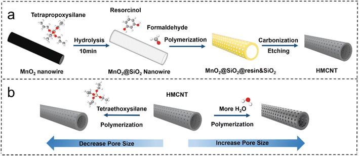
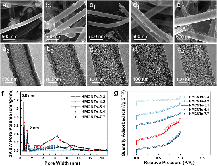
The hollow mesoporous carbon nanotubes were synthesized using a template method, as illustrated in Fig. 1. Tetrapropoxysilane (TPOS) was selected as the source of SiO2, and MnO2 nanowires were employed as the sacrificial template. Initially, SiO2 was coated onto MnO2 nanowires to obtain MnO2@SiO2 through the hydrolysis of TPOS in the solution. Then, the resorcinol-formaldehyde resin (produced by the polymerization of resorcinol and formaldehyde) and silicon dioxide (by hydrolysis of remaining TPOS) were co-condensed onto the MnO2@SiO2 nanowires, forming a coating layer mixed with resin and SiO2 on the nanowire surface (MnO2@SiO2@resin&SiO2). After the carbonization and the removal of SiO2 by HF, the hollow carbon nanotubes with open mesochannels in the tube walls were obtained (Fig. 1). Ammonia was used as both a pH regulator and catalyst during the synthesis, leading to a uniform distribution of nitrogen atoms in the synthesized hollow mesoporous carbon nanotubes, i.e. forming N-doped HMCNTs. To further adjust the size of mesopores, a pore engineering technique was used to control the pore size of the N-doped HMCNTs. By adding TEOS with various mass ratios during polymerization, N-doped HMCNTs with smaller pore sizes were prepared. Conversely, to increase the pore size, we can modify the water-to-ethanol ratio during the polymerization process (Fig. 1b). The mechanism behind the pore size tuning of hard carbon is discussed in ESI.†Fig. 2 shows five types of as-synthesized N-doped HMCNTs with average pore sizes of 2.3 nm, 4.2 nm, 5.1 nm, 6.1 nm and 7.7 nm, respectively, which are denoted as HMCNTs-2.3 (Fig. 2a), HMCNTs-4.2 (Fig. 2b), HMCNTs-5.1 (Fig. 2c), HMCNTs-6.1 (Fig. 2d) and HMCNTs-7.7 (Fig. 2e). As shown in the scanning electron microscopy (SEM) and transmission electron microscopy (TEM) images, all these HMCNTs exhibited similar hollow tubular morphologies, with the mesochannels vertically oriented with respect to the wall surface. As the pore size increased, the nanotube surface became rougher and the pore structures were more easily discernible. In addition, we attempted to further increase the average pore size to more than 7.7 nm by adjusting the synthesis conditions, but failed. The resultant nanotubes had an average pore size of only 7.6 nm (HMCNTs-7.6), and the shells were significantly fragmented, even leading to a broken tube structure (Fig. S1†). Such nanotubes also demonstrated inferior performance in Na+ storage. Therefore, the data of HMCNTs-7.6 are not listed here for comparison. The characterization and electrochemical test results of HMCNTs-7.6 are presented in ESI (Fig. S8 and S9).†
EDS mapping of the samples (Fig. S2†) reveals the uniform distribution of N and O elements in the carbon shells. The X-ray diffraction (XRD) patterns (Fig. S4a†) of the five samples present a broad diffraction peak at around 24°, indexed to (0 0 2) planes, which is typical of amorphous hard carbon.24 The Raman spectra (Fig. S4b†) display two dominant peaks centered at 1345 (D band) and 1592 cm−1 (G band).25 As expected, the five types of HMCNTs show the similar intensity ratio of ID/IG (∼1.00), suggesting comparable defective degrees.26 In addition, X-ray photoelectric spectroscopy (XPS) indicates the presence of carbon, nitrogen, and oxygen in the HMCNTs. The high-resolution C 1s XPS spectra of five samples (Fig. S5 and S6†) all comprise C–C, C–O, and C![[double bond, length as m-dash]](https://www.rsc.org/images/entities/char_e001.gif) O bonds, and all the N 1s XPS spectra can be deconvoluted into the peaks of pyridinic N and pyrrolic N, which suggest similar chemical properties of the five HMNCTs.27–29
O bonds, and all the N 1s XPS spectra can be deconvoluted into the peaks of pyridinic N and pyrrolic N, which suggest similar chemical properties of the five HMNCTs.27–29
To further reveal the difference and quantify the pore size of the series of carbon nanotubes, we conducted BET tests on all the samples. Obviously, there is a prominent increase of the slope in adsorption/desorption curve at P/P0 = 0.6–0.8 in the isothermal plots (Fig. 2g) of HMCNTs-6.1, which is more significant than the other HMCNTs. This can be attributed to the capillary condensation of N2 in the mesochannels. According to the pore size distribution (Fig. 2f), large numbers of micropores with sizes peaked at about 0.6 and 1.2 nm can be confirmed in all five samples. Different from the HMCNTs-2.3, HMCNTs-4.2 and HMCNTs-5.1 with the smaller pore size, the HMCNTs-6.1 possessed remarkable mesoporous features, as evidenced by the broad peaks at 6 nm. We observed that increasing the mesopore diameter appropriately can enlarge both the specific surface area and pore volume of HMCNTs. The increase of surface area suggests more active sites for Na-ion insertion/extraction, and the enlargement of pore volume can accommodate volume change of material during cycling and ensure sufficient electrolyte infiltration into the electrode.
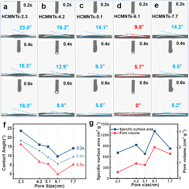
To experimentally verify whether the capillarity of mesochannels can promote the wettability between these nanotube electrodes and electrolyte at macro scale, the electrolyte (1 M NaPF6 in DME) was dripped onto the electrodes (made of the five types of HMCNTs, respectively) to measure the dynamic contact angles. As shown in Fig. 3a–e, the contact angle between the electrolyte and HMCNTs-6.1 quickly approached zero, while the other four samples exhibited appreciable contact angles at 0.6 s, suggesting superior electrolyte wettability of HMCNTs-6.1 over the other nanotubes. Besides, the contact angle (see e.g. those at 0.6 s in Fig. 3f) decreased monotonically as the average pore size increased up to 6.1 nm, but increased if the pore size was enlarged to 7.7 nm, suggesting that increasing the pore size of HMCNTs does not always improve their wettability with electrolyte. To elucidate the connection between pore size and wettability, we further examined the BET data of these nanotubes. As shown in Fig. 3g, both specific surface area and pore volume peaked at pore size of 6.1 nm. This indicates that appropriate pore enlargement can maximize the specific surface area and pore volume of carbon nanotubes, which is critical for enhancing the wettability between the electrode and electrolyte. Note that despite the larger pore size of HMCNTs-7.7, its surface area and pore volume were reduced compared to HMCNTs-6.1. It might be possible that excessive enlargement of the pore size can significantly reduce the number of pores, and therefore the specific surface area and pore volume. In short, HMCNTs-6.1 exhibited the optimized pore size effect in terms of electrolyte wettability.
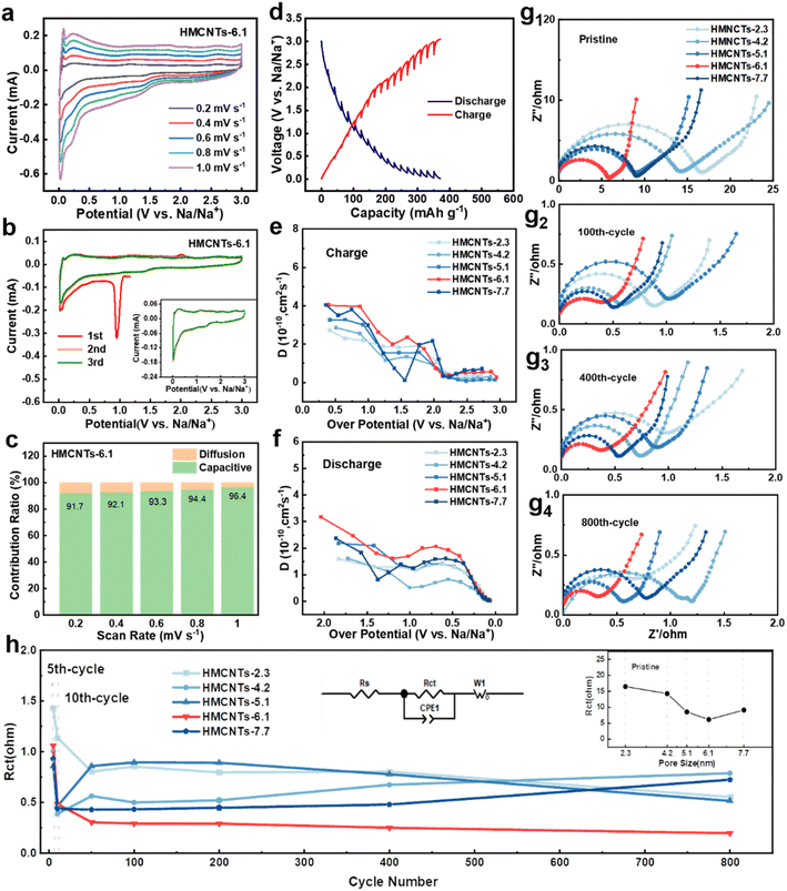
In order to investigate the mechanism and kinetics of the electrode reaction, half coin cells were assembled to perform the electrochemical tests. To explore the electrochemical kinetics of Na+ storage in the five electrodes, cyclic voltammetry (CV) rate tests were conducted at different scan rates ranging from 0.2 to 1.0 mV s−1 (Fig. 4a and S7†). Fig. 4a shows the CV curves of HMCNTs-6.1 at different scan rates, and the curves maintain a consistent shape from 0.2 mV s−1 to 1.0 mV s−1, owing to the good mechanical and electrochemical stability of HMCNTs-6.1. Fig. 4b displays the initial 3 cycles of cyclic voltammetry (CV) curves of HMCNTs-6.1 in a voltage window of 0.01–3.0 V (vs. Na/Na+) at the scan rate of 0.2 mV s−1. A sharp cathodic peak appears at 1.0 V in the first cycle and disappears in the following cycles, which can be mainly attributed to the decomposition of electrolyte and the formation of SEI.1,30 The redox peak at near 0.02 V/0.25 V refer to the intercalation/deintercalation of Na+ into graphitic domain.31 Furthermore, we can evaluate the pseudocapacitive contribution ratio of these electrodes by eqn (1):
| i = k1ν + k2ν1/2 | (1) |
As mentioned above, the greatly enhanced wettability of the mesoporous carbons can be attributed to the strong capillarity of the open mesochannels in carbon tube walls, which can draw the electrolyte into the cavity and then sufficiently infiltrate the electrode, so that the huge specific surface area can be fully utilized. This assumption is supported by the results of diffusion coefficient tests. As shown in Fig. 4d, galvanostatic intermittent titration technique (GITT) was carried out to measure the diffusion coefficient of the electrodes. The numerical value of diffusion coefficient DNa+ can be evaluated by eqn (2):
 | (2) |
Fig. 4g shows the electrochemical impedance spectroscopy measurements of five types of HMCNTs at different cycles. The charge-transfer resistance (Rct) value of the HMCNTs-6.1 electrode gradually decreases from 6.17 Ω to 0.48 Ω after 10 cycles and then becomes stable, which can be attributed to the structure reconstruction and conductivity improvement caused by the Na+ insertion.40,41 As shown in Fig. 4h, HMCNTs-6.1 possesses the minimum Rct values among the five hard carbons during the whole processes, which suggests the excellent long-term electrolyte wettability of HMCNTs-6.1 and the fastest Na+ reaction kinetics. Notably, as shown in the inset of Fig. 4h, the Rct of the five pristine HMCNTs exhibits the same dependence on pore size with the contact angle (Fig. 3f), indicating the strong linkage between the reaction kinetics and electrolyte wettability of the samples.
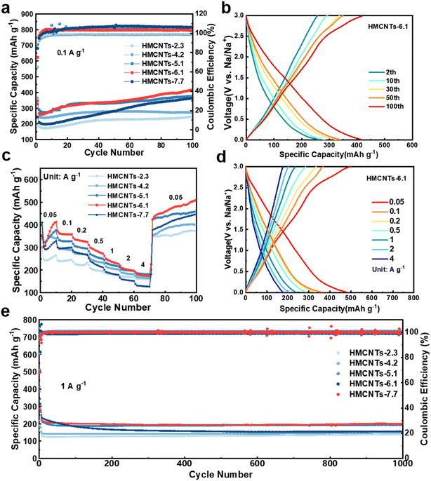
As shown in Fig. 5a, when cycled at 0.1 A g−1, HMCNTs-6.1 delivered a discharge capacity of 345.3 mA h g−1 with an initial coulombic efficiency (ICE) of 75.0% in the first cycle. From the second cycle, the specific capacity of the cell became stable and the coulombic efficiency (CE) increased gradually. At the 100th cycle, the cell can still deliver a specific capacity of 415.5 mA h g−1 with a CE of nearly 100%. In comparison, the HMCNTs-2.3, HMCNTs-4.2, HMCNTs-5.1 and HMCNTs-7.7 cells delivered specific capacities of 247.4 mA h g−1, 270.4 mA h g−1, 375.3 mA h g−1, and 363.5 mA h g−1 at 0.1 A g−1 after 100 cycles, respectively. Generally, as the pore size of the HMCNTs increases, the cell gains a higher specific capacity. HMCNTs-6.1 exhibited much higher capacity than the other four types of HMCNTs due to the enhanced wettability as discussed above. Samples with larger pores demonstrate more pronounced capillary action compared to those with smaller pores and thus have higher electrolyte wettability. Furthermore, during the cycling process, HMCNTs-5.1, HMCNTs-6.1, and HMCNTs-7.7 all exhibited an increasing trend of capacity, which can be attributed to the continuous electrolyte penetration in the mesoporous carbon electrodes throughout the cycling. For these three types of carbon nanotubes, the effective contact area gradually increases, leading to continuous increase in capacity. Conversely, for carbon nanotubes with smaller pore sizes such as HMCNTs-2.3 and HMCNTs-4.2, electrolyte penetration is limited, resulting in a less variation in the contact area between the electrolyte and electrode materials over time. Fig. 5b shows the typical charge/discharge curves of HMCNTs-6.1.
Meanwhile, compared to the other four types of HMCNTs, HMCNTs-6.1 exhibited superior rate performance, delivering capacities of 358.5, 331.3, 284.9, 236.4 and 201.8 mA h g−1 at 0.1, 0.2, 0.5, 1 and 2 A g−1, respectively (Fig. 5c). Even at a high current density of 4 A g−1, it still retained a specific capacity of 176.6 mA h g−1. Moreover, when the current density switched back to 0.05 A g−1 after cycling at 4 A g−1, the specific capacity of HMCNTs-6.1 can reach as high as 450 mA h g−1. This confirms that adjusting the pore size of hard carbon to enhance its wettability with the electrolyte can lead to faster kinetics. As shown in Fig. S10,† the rate performance of our samples was quite competitive compared with the recently reported carbonaceous SIB anodes with excellent rate performances.
Then, we further tested the long-term cyclability of HMCNTs at high current density (Fig. 5e). The coin cell was first cycled at 0.1 A g−1 for 3 times to compensate the capacity loss, and then at a current density of 1 A g−1 to test the long-term cyclability. HMCNTs-6.1 delivered a high specific capacity of 278.08 mA h g−1 after the pre-sodiation, and the capacity was maintained at around 200 mA h g−1 in subsequent cycles, outperforming the cycling specific capacities of HMCNTs-2.3, HMCNTs-4.2, HMCNTs-5.1, and HMCNTs-7.7. This further demonstrates that the Na+ storage capability of hard carbon can be markedly enhanced by appropriate pore size tuning.
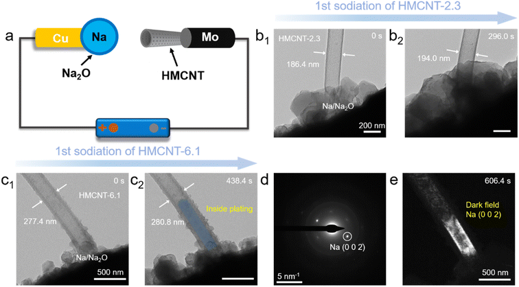
To visualize and compare the pore size effect on the shell sodiation and Na ion transport behavior of the HMCNTs, in situ TEM experiments were conducted. Two typical HMCNT with small (2.3 nm) and large (6.1 nm) pore sizes were selected for comparison. Fig. 6a illustrates the experimental setup, where a single HMCNT located on the Mo tip servers as the working electrode, while a Na/Na2O metal located on the Cu tip works as both the solid electrolyte and the counter electrode. Once the contact between a nanotube and the counter Na/Na2O electrode was established, a bias of −3 V was applied to the nanotube to initiate the reaction. Fig. 6b and c exhibits the time-resolved TEM images of HMCNT-2.3 and HMCNT-6.1 during sodiation, respectively. For HMCNT-2.3 (Fig. 6b), after 296.0 s of sodiation, the outer diameter expanded from 186.4 nm to 194.0 nm by 4.1%, while the cavity of the nanotube remained empty. For HMCNT-6.1 as shown in Fig. 6c, the nanotube experienced a slight expansion of only 1.2%, demonstrating its structural advantage of the large pores to butter the volume expansion during sodiation. Interestingly, Na metal nucleated at the bottom of the nanotube and grew upward during further reaction. As revealed by the selected-area electron diffraction (SAED) pattern from the Na-filled HMCNT-6.1 (Fig. 6d), the sharp spots are indexed as metallic Na, indicating its single-crystalline nature. The dark field (DF) image formed by selecting the sharp diffraction spot of Na (002) demonstrates that the single-crystal Na occupied the entire inner spaces of HMCNT-6.1 (Fig. 6e). The Na deposition inside HMCNT-6.1 indicates that Na ions can easily penetrate the carbon shell through the larger mesochannels. In contrast, the small pores in HMCNT-2.3 may be blocked during the sodiation process, which slows down the inward diffusion of Na ions. The driving force for Na encapsulation is the drop in Gibbs free energy associated with the Na nucleation inside a nanotube compared to its outside nucleation,42 similar to the capillary force that drive the liquid electrolyte into the HMCNTs. Our in situ TEM experiments, though conducted in a solid-state environment, suggests that the sub-10 nm mesopores with larger size are more favorable for the mass transport and electrolyte infiltration, thus greatly promoting the wettability of HMCNT-6.1.
3. Conclusion
In summary, we proposed a pore size tuning strategy to regulate the electrolyte wettability of carbonaceous anodes for improving Na+ transport kinetics. The effects of pore size on the promoted electrolyte wettability and reaction kinetics of hard carbon were thoroughly evaluated by various characterizations. It is demonstrated that increasing the pore size appropriately can enhance the specific surface area and pore volume of carbon nanotubes, thereby improving the electrode's wettability to electrolyte and its reaction kinetics. The HMCNTs-6.1 electrode demonstrate the optimal electrochemical performance among the series of HMCNTs anodes. This work provides new insight for enhanced Na+ storage from the perspective of the pore-size tuning of mesoporous hard carbons, which can be practically used in the design of advanced SIB anodes.4. Experimental section
Preparation of HMCNTs
First, 2 mmol MnSO4·H2O, 3.5 mmol KClO3 and 3.5 mmol CH3COOK were dissolved in 30 mL deionized water with stirring to form a clear solution. After adding 1.6 mL acetic acid, the solution was transferred to a 50 mL Teflon-lined autoclave and then kept in an oven at 160 °C for 8 hours. The resulting product collected by centrifugation was MnO2 nanowires. Then, these MnO2 nanowires as the template were added into a solution that contained 10 mL deionized water, 3 mL 30 wt% ammonia and 70 mL ethanol. After thorough stirring, 2 mL tetrapropoxysilane (TPOS) was added in this solution with stirring at 30 °C for 10 minutes. Then, 400 mg resorcinol and 0.56 mL 37 wt% formaldehyde were added into the solution under stirring for 24 hours. The precursor of HMCNT6.1 was obtained by centrifugation, washed by deionized water and ethanol, and dried at 60 °C for 8 hours. After carbonized at 800 °C at a heating rate of 2 °C per minute under Ar atmosphere for 4 hours, we can obtain SiO2@HMCNTs-6.1. To remove SiO2, the resulting product was washed by 15 wt% hydrofluoric acid. The final product of HMCNTs-6.1 was thus obtained.The preparation process of HMCNTs-2.3, HMCNTs-4.2 and HMCNTs-5.1 was similar with that of HMCNT6.1, and the only difference was that the 2 mL TPOS in the above preparation scheme is replaced by an equal amount of TPOS/tetraethoxysilane (TEOS) mixture (with volume ratios of 0![[thin space (1/6-em)]](https://www.rsc.org/images/entities/char_2009.gif) :
:![[thin space (1/6-em)]](https://www.rsc.org/images/entities/char_2009.gif) 1, 1
1, 1![[thin space (1/6-em)]](https://www.rsc.org/images/entities/char_2009.gif) :
:![[thin space (1/6-em)]](https://www.rsc.org/images/entities/char_2009.gif) 2, 2
2, 2![[thin space (1/6-em)]](https://www.rsc.org/images/entities/char_2009.gif) :
:![[thin space (1/6-em)]](https://www.rsc.org/images/entities/char_2009.gif) 1, respectively). The preparation process of HMCNT7.6 and HMCNTs-7.7 was also similar with that of HMCNT6.1, and the only difference was to change the ethanol/water ratio in the above preparation scheme (5
1, respectively). The preparation process of HMCNT7.6 and HMCNTs-7.7 was also similar with that of HMCNT6.1, and the only difference was to change the ethanol/water ratio in the above preparation scheme (5![[thin space (1/6-em)]](https://www.rsc.org/images/entities/char_2009.gif) :
:![[thin space (1/6-em)]](https://www.rsc.org/images/entities/char_2009.gif) 3, 6
3, 6![[thin space (1/6-em)]](https://www.rsc.org/images/entities/char_2009.gif) :
:![[thin space (1/6-em)]](https://www.rsc.org/images/entities/char_2009.gif) 2, respectively).
2, respectively).
Material characterization
Scanning electron microscopy (SEM, Zeiss SIGMA) and Transmission electron microscopy (TEM, FEI Talos F200s) were utilized to characterize the morphology and microstructure of the samples. Specific surface areas and pore sizes distribution were measured by N2 isothermal adsorption and desorption with Micromeritics ASAP 2460 analyzer. Photos of the contact angle between electrolyte (1 M NaPF6 in DME) and electrode were taken with the use of KrüSS DSA100 drop shape analyzer. X-ray Diffraction (XRD) analysis was performed on a Bruker-AXS D8-A25 X-ray diffractometer equipped with Cu-Kα radiation. Raman spectra were conducted on Horiba France Sas HR Evolution confocal Raman microscope using a 532 nm excitation laser. X-ray photoelectron spectroscopy (XPS) was conducted on a Thermo Scientific K-Alpha spectrometer equipped with Al Kα radiation.Electrochemical measurements
The samples, i.e. the active materials, were mixed with conductive agent (Super P) and carboxymethylcellulose binder with a weight ratio of 75![[thin space (1/6-em)]](https://www.rsc.org/images/entities/char_2009.gif) :
:![[thin space (1/6-em)]](https://www.rsc.org/images/entities/char_2009.gif) 10
10![[thin space (1/6-em)]](https://www.rsc.org/images/entities/char_2009.gif) :
:![[thin space (1/6-em)]](https://www.rsc.org/images/entities/char_2009.gif) 15 to form homogeneous slurry. The slurry was pasted on Cu foil uniformly and dried under vacuum at 60 °C overnight. The mass loading of the active material was weighed to be 0.8–1.0 mg cm−2. The coin cells (2016) were assembled in an Ar-filled glove box (Mikrouna), in which the concentration of H2O and O2 were maintained below 1 ppm. The Cu foil pasted with active material was used as working electrode, sodium metal was used as counter/reference electrode, glass fiber was used as separator, and the electrolyte was a 1 M NaPF6 solution dissolved in dimethyl ether (DME).
15 to form homogeneous slurry. The slurry was pasted on Cu foil uniformly and dried under vacuum at 60 °C overnight. The mass loading of the active material was weighed to be 0.8–1.0 mg cm−2. The coin cells (2016) were assembled in an Ar-filled glove box (Mikrouna), in which the concentration of H2O and O2 were maintained below 1 ppm. The Cu foil pasted with active material was used as working electrode, sodium metal was used as counter/reference electrode, glass fiber was used as separator, and the electrolyte was a 1 M NaPF6 solution dissolved in dimethyl ether (DME).
The long-term cycling measurements and rate capability tests were conducted at 30 °C by Neware MIHW-200-160CH integrated constant temperature cells testing system. GITT measurements were performed by LAND-CT2001A at room temperature within a potential range of 0.01–3.0 V (vs. Na/Na +). CV and EIS curves were collected on Chenhua CHI660E electrochemical workstation.
In situ TEM observations
The sodiation/plating behaviors of our materials were in situ observed in FEI Talos F200s TEM with 200 kV acceleration voltage. The HMCNTs samples were attached to a molybdenum tip that acted as the working electrode, a small amount of Na metal was loaded on a Cu tip that worked as the counter electrode, and the naturally formed Na2O wrapped on Na metal served as the solid electrolyte. Thus, we constructed a nanoscale cell to mimic the circumstance for sodium ion insertion into our materials. A constant bias of −3.0 V was applied to the working electrode when the Na2O/Na electrode was brought into contact with our materials to trigger the sodiation/plating processes.Conflicts of interest
There are no conflicts to declare.Acknowledgements
This work was financially supported by the National Natural Science Foundation of China (Grants No. 52172240), the China Postdoctoral Science Foundation (Grants No. 2022M712655), the Fundamental Research Funds for the Central Universities (Grant No. 20720230043), and the “Double-First Class” Foundation of Materials and Intelligent Manufacturing Discipline of Xiamen University.References
- X. Y. Chen, J. Y. Tian, P. Li, Y. L. Fang, Y. J. Fang, X. M. Liang, J. W. Feng, J. Dong, X. P. Ai, H. X. Yang and Y. L. Cao, Adv. Energy Mater., 2022, 12, 2200886 CrossRef CAS.
- Y. S. Tian, G. B. Zeng, A. Rutt, T. Shi, H. Kim, J. Y. Wang, J. Koettgen, Y. Z. Sun, B. Ouyang, T. N. Chen, Z. Y. Lun, Z. Q. Rong, K. Persson and G. Ceder, Chem. Rev., 2021, 121, 1623–1669 CrossRef CAS PubMed.
- J. X. Xu, Y. W. Liu, C. W. Xu, J. Li, Z. W. Yang, H. H. Yan, H. X. Yu, L. Yan, L. Y. Zhang and J. Shu, Coord. Chem. Rev., 2023, 474, 214867 CrossRef CAS.
- F. Xie, Z. Xu, Z. Y. Guo, Y. X. Lu, L. Q. Chen, M. M. Titirici and Y. S. Hu, Sci. China Chem., 2021, 64, 1679–1692 CrossRef CAS.
- H. M. Zhang, S. W. Zhao and F. Q. Huang, J. Mater. Chem. A, 2021, 9, 27140–27169 RSC.
- C. Bommier, T. W. Surta, M. Dolgos and X. L. Ji, Nano Lett., 2015, 15, 5888–5892 CrossRef CAS PubMed.
- R. A. Adams, A. Varma and V. G. Pol, Adv. Energy Mater., 2019, 9, 1900550 CrossRef.
- S. Qiu, L. F. Xiao, M. L. Sushko, K. S. Han, Y. Y. Shao, M. Y. Yan, X. M. Liang, L. Q. Mai, J. W. Feng, Y. L. Cao, X. P. Ai, H. X. Yang and J. Liu, Adv. Energy Mater., 2017, 7, 1700403 CrossRef.
- X. W. Dou, I. Hasa, D. Saurel, C. Vaalma, L. M. Wu, D. Buchholz, D. Bresser, S. Komaba and S. Passerini, Mater. Today, 2019, 23, 87–104 CrossRef CAS.
- A. Ponrouch, A. R. Goñi and M. R. Palacín, Electrochem. Commun., 2013, 27, 85–88 CrossRef CAS.
- D. Q. Chen, W. Zhang, K. Y. Luo, Y. Song, Y. J. Zhong, Y. X. Liu, G. K. Wang, B. H. Zhong, Z. G. Wu and X. D. Guo, Energy Environ. Sci., 2021, 14, 2244–2262 RSC.
- C. C. Sun, F. J. Kong, L. L. Fan, S. Tao, G. K. Zhang, S. Q. Chu, W. S. Chu and L. Song, Chem. Eng. J., 2023, 470, 144419 CrossRef CAS.
- X. C. Sun, X. Gao, Z. Li, X. Zhang, X. L. Zhai, Q. X. Zhang, L. A. Li, N. Gao, G. J. He and H. D. Li, Small Methods, 2024, 8, 2300746 CrossRef CAS PubMed.
- J. Kim, M. S. Choi, K. H. Shin, M. Kota, Y. B. Kang, S. Lee, J. Y. Lee and H. S. Park, Adv. Mater., 2019, 31, 1803444 CrossRef PubMed.
- Z. H. Tian, Y. Zhang, J. X. Zhu, Q. Y. Li, T. X. Liu and M. Antonietti, Adv. Energy Mater., 2021, 11, 2102489 CrossRef CAS.
- Y. X. Chen, B. J. Xi, M. Huang, L. L. Shi, S. Z. Huang, N. N. Guo, D. Li, Z. C. Ju and S. L. Xiong, Adv. Mater., 2022, 34, 2108621 CrossRef CAS PubMed.
- Y. S. Wang, Z. P. Wang, Y. J. Chen, H. Zhang, M. Yousaf, H. S. Wu, M. C. Zou, A. Y. Cao and R. P. S. Han, Adv. Mater., 2018, 30, 1802074 CrossRef PubMed.
- Z. H. Yan, Q. W. Yang, Q. H. Wang and J. M. Ma, Chin. Chem. Lett., 2020, 31, 583–588 CrossRef CAS.
- W. X. Yang, J. H. Zhou, S. Wang, W. Y. Zhang, Z. C. Wang, F. Lv, K. Wang, Q. Sun and S. J. Guo, Energy Environ. Sci., 2019, 12, 1605–1612 RSC.
- Z. F. Li, C. Bommier, Z. Sen Chong, Z. L. Jian, T. W. Surta, X. F. Wang, Z. Y. Xing, J. C. Neuefeind, W. F. Stickle, M. Dolgos, P. A. Greaney and X. L. Ji, Adv. Energy Mater., 2017, 7, 1602894 CrossRef.
- M. H. Zhang, Y. Li, F. Wu, Y. Bai and C. Wu, Nano Energy, 2021, 82, 105738 CrossRef CAS.
- D. H. Jeon, Energy Storage Mater., 2019, 18, 139–147 CrossRef.
- S. F. Lei, X. F. Chen, B. B. Xiao, W. T. Zhang and J. Liu, ACS Appl. Mater. Interfaces, 2019, 11, 28830–28840 CrossRef CAS PubMed.
- M. Chen, W. Wang, X. Liang, S. Gong, J. Liu, Q. Wang, S. J. Guo and H. Yang, Adv. Energy Mater., 2018, 8, 1800171 CrossRef.
- W. D. Qiu, H. B. Xiao, Y. Li, X. H. Lu and Y. X. Tong, Small, 2019, 15, 1901285 CrossRef PubMed.
- C. Lu, Z. T. Sun, L. H. Yu, X. Y. Lian, Y. Y. Yi, J. Li, Z. F. Liu, S. X. Dou and J. Y. Sun, Adv. Energy Mater., 2020, 10, 2001161 CrossRef CAS.
- R. L. Huang, X. X. Zhang, Z. X. Qu, X. D. Zhang, J. Lin, F. Wu, R. J. Chen and L. Li, J. Mater. Chem. A, 2022, 10, 682–689 RSC.
- W. Wang, L. Shang, G. J. Chang, C. Y. Yan, R. Shi, Y. X. Zhao, G. I. N. Waterhouse, D. J. Yang and T. R. Zhang, Adv. Mater., 2019, 31, 1808276 CrossRef PubMed.
- T. Sun, W. J. Zang, H. Yan, J. Li, Z. Q. Zhang, Y. F. Bu, W. Chen, J. Wang, J. Lu and C. L. Su, ACS Catal., 2021, 11, 4498–4509 CrossRef CAS.
- J. M. Chen, Y. Cheng, Q. B. Zhang, C. Luo, H. Y. Li, Y. Wu, H. H. Zhang, X. Wang, H. D. Liu, X. He, J. J. Han, D. L. Peng, M. L. Liu and M. S. Wang, Adv. Funct. Mater., 2021, 31, 2007158 CrossRef CAS.
- J. H. Han, I. Johnson, Z. Lu, A. Kudo and M. W. Chen, Nano Lett., 2021, 21, 6504–6510 CrossRef CAS PubMed.
- V. Augustyn, P. Simon and B. Dunn, Energy Environ. Sci., 2014, 7, 1597–1614 RSC.
- C. Cui, Z. X. Wei, G. Zhou, W. F. Wei, J. M. Ma, L. B. Chen and C. C. Li, J. Mater. Chem. A, 2018, 6, 7088–7098 RSC.
- P. Ge, H. S. Hou, S. J. Li, L. P. Huang and X. B. Ji, ACS Appl. Mater. Interfaces, 2018, 10, 14716–14726 CrossRef CAS PubMed.
- Z. H. Gan, J. Y. Yin, X. Xu, Y. H. Cheng and T. Yu, ACS Nano, 2022, 16, 5131–5152 CrossRef CAS PubMed.
- B. Zhao, Q. Q. Liu, Y. J. Chen, Q. Liu, Q. Yu and H. B. Wu, Adv. Funct. Mater., 2020, 30, 2002019 CrossRef CAS.
- P. Song, S. Q. Wei, J. Di, J. Du, W. J. Xu, D. B. Liu, C. D. Wang, S. C. Qiao, Y. Y. Cao, Q. L. Cui, P. J. Zhang, L. B. Ma, J. W. Cui, Y. Wang and Y. J. Xiong, Nano Res., 2023, 16, 4874–4879 CrossRef CAS.
- Y. M. Li, Y. S. Hu, M. M. Titirici, L. Q. Chen and X. J. Huang, Adv. Energy Mater., 2016, 6, 1600659 CrossRef.
- F. J. Kong, Z. S. Han, S. Tao and B. Qian, J. Energy Chem., 2021, 55, 256–264 CrossRef CAS.
- H. L. Deng, L. Wang, S. Y. Li, M. Zhang, T. Wang, J. Zhou, M. X. Chen, S. Chen, J. H. Cao, Q. S. Zhang, J. Zhu and B. A. Lu, Adv. Funct. Mater., 2021, 31, 2107246 CrossRef CAS.
- Z. X. Pei, Q. Q. Meng, L. Wei, J. Fan, Y. Chen and C. Y. Zhi, Energy Storage Mater., 2020, 28, 55–63 CrossRef.
- P. Wei, Y. Cheng, X. L. Yan, W. B. Ye, X. N. Lan, L. A. Wang, J. J. Sun, Z. Y. Yu, G. F. Luo, Y. Yang, M. H. Rummeli and M. S. Wang, Adv. Mater., 2021, 33, 2105228 CrossRef CAS PubMed.
Footnote |
| † Electronic supplementary information (ESI) available. See DOI: https://doi.org/10.1039/d4ta02303j |
| This journal is © The Royal Society of Chemistry 2024 |

